EP2561223B1 - Windkraftgenerator mit einem luftverdichter - Google Patents
Windkraftgenerator mit einem luftverdichter Download PDFInfo
- Publication number
- EP2561223B1 EP2561223B1 EP11723648.9A EP11723648A EP2561223B1 EP 2561223 B1 EP2561223 B1 EP 2561223B1 EP 11723648 A EP11723648 A EP 11723648A EP 2561223 B1 EP2561223 B1 EP 2561223B1
- Authority
- EP
- European Patent Office
- Prior art keywords
- air
- wind
- generator
- rotor
- air compressor
- Prior art date
- Legal status (The legal status is an assumption and is not a legal conclusion. Google has not performed a legal analysis and makes no representation as to the accuracy of the status listed.)
- Active
Links
Images


Classifications
-
- F—MECHANICAL ENGINEERING; LIGHTING; HEATING; WEAPONS; BLASTING
- F03—MACHINES OR ENGINES FOR LIQUIDS; WIND, SPRING, OR WEIGHT MOTORS; PRODUCING MECHANICAL POWER OR A REACTIVE PROPULSIVE THRUST, NOT OTHERWISE PROVIDED FOR
- F03D—WIND MOTORS
- F03D9/00—Adaptations of wind motors for special use; Combinations of wind motors with apparatus driven thereby; Wind motors specially adapted for installation in particular locations
- F03D9/10—Combinations of wind motors with apparatus storing energy
- F03D9/17—Combinations of wind motors with apparatus storing energy storing energy in pressurised fluids
-
- F—MECHANICAL ENGINEERING; LIGHTING; HEATING; WEAPONS; BLASTING
- F03—MACHINES OR ENGINES FOR LIQUIDS; WIND, SPRING, OR WEIGHT MOTORS; PRODUCING MECHANICAL POWER OR A REACTIVE PROPULSIVE THRUST, NOT OTHERWISE PROVIDED FOR
- F03D—WIND MOTORS
- F03D9/00—Adaptations of wind motors for special use; Combinations of wind motors with apparatus driven thereby; Wind motors specially adapted for installation in particular locations
- F03D9/20—Wind motors characterised by the driven apparatus
- F03D9/28—Wind motors characterised by the driven apparatus the apparatus being a pump or a compressor
-
- Y—GENERAL TAGGING OF NEW TECHNOLOGICAL DEVELOPMENTS; GENERAL TAGGING OF CROSS-SECTIONAL TECHNOLOGIES SPANNING OVER SEVERAL SECTIONS OF THE IPC; TECHNICAL SUBJECTS COVERED BY FORMER USPC CROSS-REFERENCE ART COLLECTIONS [XRACs] AND DIGESTS
- Y02—TECHNOLOGIES OR APPLICATIONS FOR MITIGATION OR ADAPTATION AGAINST CLIMATE CHANGE
- Y02E—REDUCTION OF GREENHOUSE GAS [GHG] EMISSIONS, RELATED TO ENERGY GENERATION, TRANSMISSION OR DISTRIBUTION
- Y02E10/00—Energy generation through renewable energy sources
- Y02E10/70—Wind energy
- Y02E10/72—Wind turbines with rotation axis in wind direction
-
- Y—GENERAL TAGGING OF NEW TECHNOLOGICAL DEVELOPMENTS; GENERAL TAGGING OF CROSS-SECTIONAL TECHNOLOGIES SPANNING OVER SEVERAL SECTIONS OF THE IPC; TECHNICAL SUBJECTS COVERED BY FORMER USPC CROSS-REFERENCE ART COLLECTIONS [XRACs] AND DIGESTS
- Y02—TECHNOLOGIES OR APPLICATIONS FOR MITIGATION OR ADAPTATION AGAINST CLIMATE CHANGE
- Y02E—REDUCTION OF GREENHOUSE GAS [GHG] EMISSIONS, RELATED TO ENERGY GENERATION, TRANSMISSION OR DISTRIBUTION
- Y02E60/00—Enabling technologies; Technologies with a potential or indirect contribution to GHG emissions mitigation
- Y02E60/16—Mechanical energy storage, e.g. flywheels or pressurised fluids
-
- Y—GENERAL TAGGING OF NEW TECHNOLOGICAL DEVELOPMENTS; GENERAL TAGGING OF CROSS-SECTIONAL TECHNOLOGIES SPANNING OVER SEVERAL SECTIONS OF THE IPC; TECHNICAL SUBJECTS COVERED BY FORMER USPC CROSS-REFERENCE ART COLLECTIONS [XRACs] AND DIGESTS
- Y02—TECHNOLOGIES OR APPLICATIONS FOR MITIGATION OR ADAPTATION AGAINST CLIMATE CHANGE
- Y02E—REDUCTION OF GREENHOUSE GAS [GHG] EMISSIONS, RELATED TO ENERGY GENERATION, TRANSMISSION OR DISTRIBUTION
- Y02E70/00—Other energy conversion or management systems reducing GHG emissions
- Y02E70/30—Systems combining energy storage with energy generation of non-fossil origin
-
- Y—GENERAL TAGGING OF NEW TECHNOLOGICAL DEVELOPMENTS; GENERAL TAGGING OF CROSS-SECTIONAL TECHNOLOGIES SPANNING OVER SEVERAL SECTIONS OF THE IPC; TECHNICAL SUBJECTS COVERED BY FORMER USPC CROSS-REFERENCE ART COLLECTIONS [XRACs] AND DIGESTS
- Y02—TECHNOLOGIES OR APPLICATIONS FOR MITIGATION OR ADAPTATION AGAINST CLIMATE CHANGE
- Y02P—CLIMATE CHANGE MITIGATION TECHNOLOGIES IN THE PRODUCTION OR PROCESSING OF GOODS
- Y02P70/00—Climate change mitigation technologies in the production process for final industrial or consumer products
- Y02P70/50—Manufacturing or production processes characterised by the final manufactured product
Definitions
- the present invention relates to a wind generator of compressed air and a system for the production and storage of corrpressed air comprising said generator.
- the corrpressed air thus generated can be sent directly to the utilities or can be stored for example in compressed air tanks.
- the devices of the prior art are not optimised however and do not permit functioning in scarce wind conditions.
- the limited efficiency makes it impossible to achieve adequate pressures of corrpressed air or to store large quantities of compressed air in the tanks.
- the purpose of the present invention is to overcome the drawbacks and limitations mentioned with reference to the prior art.
- reference numeral 4 globally denotes a wind generator of corrpressed air according to the present invention.
- the wind generator 4 comprises at least one wind blade 8 joined at one end to a rotation shaft 12 having a rotation axis X-X and suitable to be driven so as to rotate around said rotation axis X-X, under the influence of a flow of air 16. Consequently, the at least one wnd blade 8 and the rotation shaft 12 constitute the rotor 5 of the wind generator.
- said rotor 5 comprises three wind blades, angularly distanced by 120é from each other.
- At least one air compressor 20 is operatively connected to said rotation shaft 12 so as to be driven by the rotor 5 to produce compressed air.
- the air compressor 20 is positioned behind the rotor 5 in relation to the direction which the flow of ai r acting on the rotor comes from Consequently, the flow of air acts directly on the wind blade 8, without the interposition of elements of disturbance.
- the generator 4 further comprises an air conveyor 22 which surrounds and contains the air compressor 20 at I east partially.
- Said air conveyor 22 has at least an entrance aperture 23, that is an air intake, suitable to convey on the air compressor 20 part of the flow of air acting on the rotor, and at least one exit aperture 24 suitable to convey the flow of air in exit at the air compressor 20.
- a rear rudder 30 is positioned downstream of the air compressor 20, to direct the rotor 5 perpendicular to the air flow.
- the air conveyor 22 performs a dual function: cooling the air compressor 20 and conveying the air flow towards the rear rudder 30 so that it can position itself parallel to the direction of the wind.
- the rotation shaft 12, the air compressor 20, the air conveyor 22 and the rudder 30 are supported by a support arm 40.
- Said support arm 40 is mounted at the top of a support structure 42, for example of the pylon type.
- said structure is made for example in aluminium sections, so as to prove particularly resistant and at the same time flexible to withstand even strong winds, economical to produce and easy to assemble.
- the support arm 40 is, further, mounted so as to rotate in relation to the vertical orientation axis Z-Z so as to be able to tilt under the effect of the thrust of the air flow acting on the rear rudder 30.
- the support arm 40 is vertically pivoted to a post 44 of the support structure 42.
- the vertical pin 40' for the directional rotation of the support arm 40 around the orientation axis Z-Z.
- the vertical orientation axis Z-Z intersects the rotation axis of the rotor 5 between it and the air compressor 20.
- the air conveyor 22 is axial-symmetric in relation to the rotation axis X-X, so as to direct the flow of air symmetrically towards the rear rudder 30.
- the air compressor 20 is of the two opposite pistons type.
- such type of air compressor 20 is highly efficient even at a low number of revs, such as 200 revs/minute, and may therefore be directly coupled to the rotation shaft 12 of the wind blade 8. Consequently, it is possible to avoid the use of intermediate gears, counter gears or other rev multiplier devices between the rotation shaft 12 of the rotor 5 and the air compressor shaft 20, reducing friction and thereby improving efficiency in transmission of the torque to the rotation shaft 12 of the rotor of the air compressor shaft 20.
- such air compressor 20 is able to self-lubricate even functioning at a low number of revs.
- the air compressor 20 comprises a central body 20' coaxial and coupled to the rotation shaft 12 of the rotor 5 and a pair of lateral expansions 20" which extend radially from opposite sides of said central body 20'.
- a pair of lateral expansions 20" which extend radially from opposite sides of said central body 20'.
- one piston of the pair of opposite pistons is housed.
- the air conveyor 22 has an outline which adapts to the shape of the air compressor 20.
- the air conveyor 22 therefore comprises two lateral portions 22" which surround and contain the lateral expansions 20" of the air compressor 20.
- Each lateral portion has an entrance aperture 23 of the air flow and exit aperture 24 of the air flow.
- the coupling hub 5' of the wind blade 8 to the rotation shaft 12 is covered on the front by an ogive- shaped closed cap 6, with a tip coaxial to the rotation axis X-X.
- the air compressor 20 is axially distanced from the coupling hub 5' of the wind blade 8 to the rotation shaft 12.
- the air conveyor 22 comprises a central front portion 22' which connects frontally to the hub 5'.
- Said central front portion 22' of the air conveyor 22 is a substantially cylindrical shape with a cross-section substantially the same as that of the hub 5', so as to be a continuation of the ogive cap 6.
- said central portion 22' connects to the lateral portions 22" of the air conveyor 22 delimiting with them the air entrance apertures 23.
- the ogive cap 6 covering the hub acts as a tapered tip for the air conveyor 22; thanks to such configuration, the air flow which frontally impacts the generator tends therefore to be directed towards the entrance apertures of the air conveyor 22, increasing both the cooling efficiency of the air compressor 20 and, coming out of the air conveyor 22, the pressure on the rear rudder 30.
- this configuration of the generator optimises the passage of the air flow in the air conveyor 22, it is possible to reduce the dimensions of the air conveyor 22 itself to the minimum required, especially in a transversal direction.
- this also entails that the wind blade 8, the active impact portion with the air flow of which extends outside said cap and therefore beyond the dimensions of the air conveyor 22, has no obstruction in front of it or behind it and the air flow which acts on said active portion is not "soiled" by the presence of the air conveyor 22.
- the at least one wind blade 8 is twisted along its main extension axis Y-Y, perpendicular to the rotation axis X-X. More in detail, the wind blade 8 has a twisting axis S-S, which identifies a twisting angle ⁇ in relation to the main extension axis Y-Y.
- the wind blade 8 may be composed of two or more elements fixed in relation to each other, for example with a slotted coupling.
- each wind blade 8 is joined to the rotation shaft 12 so as to rotate in relation to the main extension axis Y-Y and comprises motorised means (not shown) suitable to rotate the blade 8 in relation to said main extension axis Y-Y so as to vary the incidence in relation to the air flow 16.
- each blade 8 is made from aluminium, extruded aluminium alloy or other lightweight materials. It may have a hollow, box-shaped cross-section provided with strengthening ribs 52. In one embodiment, said cross-section consists of two or more elements joined to each other.
- an electro-pneumatic brake 60 suitable to limit the speed of rotation of the blades within a predefined safety value is operatively connected to the rotation shaft 12 of the rotor 5.
- Said brake 60 is controlled by a wind speed detector 62, for example an anemometer mounted on the air conveyor 22.
- the electro-pneumatic brake 60 comprises a pneumatic cylinder 64 acting on a spring 65 of a brake 65' operating directly on the rotation shaft 12 of the rotor 5.
- the pneumatic cylinder 64 is controlled by a relative solenoid valve 66.
- the pneumatic cylinder 64 is normally pressurised so as to compress the spring 65 of the brake and leave the rotation shaft 12 free to rotate.
- the pneumatic cylinder 64 suffers a pressure drop which prevents the corrpressi on of the spring and thereby enables the brake 65' to act on the rotation shaft 12.
- the rear rudder 30 is hinged to the support arm 40, so as to be rotatable in a position substantially orthogonal to said arm when the wind is excessively strong, so as to prevent the functioning of the generator.
- Such rotation of the rudder is for example triggered by an electro-pnematic safety device controlled by a wind speed detector 62, for example the anemometer mounted on the air conveyor 22.
- the safety device also comprises a pneumatic cylinder 64 acting on a spring suitable to cause the rudder 30 to rotate, and a solenoid valve 66 commanding said pneumatic cylinder 64.
- the pneumatic cylinder 64 is normally kept under pressure so as to compress the spring preventing rotation of the rudder 30; in the presence of excessively strong wind, the pneumatic cylinder 64 is discharged, depressurised, so as to leave the spring free to rotate the rudder.
- the solenoid command valve 66 of the brake cylinder and/or safety device is powered electrically by a dynamo 68.
- Said dynamo 68 may be fitted with a turbine drivable in rotation by the compressed air produced by the air compressor 20, or, in the case of use of an anemometer 62, can be operatively connected to the rotation shaft of said anemometer 62.
- the solenoid command valve 66 receives the electric command signal from a dedicated control unit 67, mounted for example on the wind generator, connected to the wind speed detector 62.
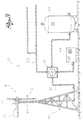
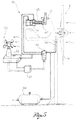
- the wind generator of compressed air is part of a system 80 for the production and storage of compressed air.
- a system 80 for the production and storage of compressed air comprises, as well as the wind generator 4 described above, at least one tank of compressed air 84 connected to the air compressor 20 by means of a compressed air duct 88 so as to receive and contain compressed air sent from the generator 4.
- said compressed air duct 88 is connected to the air compressor 20 of the wind generator by means of a low friction swivel joint 90 and comprises specific piping, for example in aluminium. Consequently, the connection of the generator to the compressed air duct does not significantly limit the ability of the generator to tilt in relation to the vertical orientation axis.
- the system 80 further comprises a distribution line 92 of compressed air which can be connected to other pneumatic utilities and a traditional motor-compressor 94.
- a distribution line 92 of compressed air which can be connected to other pneumatic utilities and a traditional motor-compressor 94.
- said motor compressor 94 may be considered an auxiliary compressor which intervenes to power the pneumatic utilities and/or the tank 84 in the case of prolonged absence of wind and therefore of a prolonged stop of the air compressor 20 of the wind generator.
- the compressor 20 of the wind generator can be used in conjunction with a traditional motor compressor 94 to achieve a significant energy saving.
- An electro-pneumatic control panel 96 is positioned between the wind generator, tank, distribution line and the motor compressor programmed to manage the flows of compressed air from the wind generator 4 or from the motor compressor 94 to the distribution line 92 or to the tank 84.
- the control panel 96 for example comprising a PLC, receives information on the air pressure in the pneumatic utilities and in the tank thanks to respective pressure switches.
- the pneumatic utilities are powered exclusively or mainly by the wind generator 4.
- the excess air is stored in the tank 84.
- the pneumatic utilities are powered by the compressed air contained in the tank 84.
- the motor compressor 94 cuts in and powers the pneumatic utilities, if necessary filling the tank 84.
- the generator according to the invention makes it possible to overcome the limitations and drawbacks mentioned with reference to the prior art.
- the wind generator gives high performance and is able to produce compressed air even in non-optimal wind conditions.
- the wind generator is mounted on a swivelling support arm 40 able to tilt depending on the effective and instantaneous direction of the wind: this way it optimises the function of the wind blades in that it can self-direct in relation to the effective wind direction.
- the blades are tilted and, preferably, are mounted on the rotor 5 so as to be able to vary their incidence in real time even during normal functioning of the blades.
- the generator is fitted with a tapered reduced size air conveyor 22 able to both efficiently cool the air compressor mounted on the generator and to direct the flow of air traversing it towards the rear rudder 30.
- the air compressor and the conveyor associated with it do not entail a reduction in performance of the generator.
- the generator is able to adapt in real time to minimal changes in the wind direction and/or intensity so as to enable optimal functioning of the wind blades.
- the generator is configured so to perform cooling of the air compressor 20 using the same wind which drives the blades.
- a further characteristic optimising the performance of the generator consists of the fact that the compressed air can be stored in a tank by means of a pipe which connects the air compressor 20 to the tank, fitted with a low friction high performance swivel joint. Such joint limits the pressure drops and resistance to rotation of the support arm 40.
- the generator is particularly safe inasmuch as provided with dedicated systems limiting overload and preventing risks of structural collapse caused by excessively high winds.
- the compressed air produced by the wind generator is also used to power said safety devices pneumatically and electrically.
- the generator and system provide a plurality of characteristics, making it possible to optimise the production of compressed air both in terms of using wind energy and in terms of reducing loss of head in sending the air to the tank or pneumatic utilities.
- the generator according to the present invention makes it possible to store large quantities of clean, low cost energy, in the form of compressed air.
- the generator has a functioning which immediately adapts to the direction and intensity of the wind.
- the generator is also simple, inexpensive to make and requires little maintenance, ensuring long duration and reliability.
Landscapes
- Engineering & Computer Science (AREA)
- Power Engineering (AREA)
- Life Sciences & Earth Sciences (AREA)
- Sustainable Development (AREA)
- Sustainable Energy (AREA)
- Chemical & Material Sciences (AREA)
- Combustion & Propulsion (AREA)
- Mechanical Engineering (AREA)
- General Engineering & Computer Science (AREA)
- Wind Motors (AREA)
- Other Liquid Machine Or Engine Such As Wave Power Use (AREA)
Claims (15)
- Druckluft-Windkraftgenerator (4), Folgendes umfassend:- einen Rotor (5), der mindestens ein Windrotorblatt (8) umfasst, das an einem Ende an eine Drehwelle (12) gefügt ist, die eine Drehachse (X-X) aufweist und geeignet ist, angetrieben zu werden, um sich unter dem Einfluss eines Luftstroms (16) um die Drehachse (X-X) zu drehen,- mindestens einen Luftverdichter (20), der in Wirkverbindung mit der Drehwelle (12) ist, sodass er von der Drehung des Rotors (5) angetrieben wird, um verdichtete Luft zu erzeugen, wobei der Luftverdichter (20) in Bezug auf die Richtung, aus der der Luftstrom kommt, der auf den Rotor (5) einwirkt, hinter dem Rotor (5) positioniert ist,- einen Luftförderer (22), der den Luftverdichter (20) mindestens teilweise umgibt und einschließt und mindestens eine Eintrittsöffnung (23), die geeignet ist, um einen Teil des Luftstroms, der auf den Rotor (5) einwirkt, auf den Luftverdichter (20) zu fördern, und mindestens eine Austrittsöffnung (24), die geeignet ist, den Luftstrom beim Austreten an der Rückseite des Luftverdichters (20) zu fördern, aufweist, und- ein rückseitiges Ruder (30), das dem Luftverdichter (20) nachgelagert positioniert ist, um den Rotor (5) senkrecht zu dem Luftstrom zu leiten;wobei die Drehwelle (12), der Luftverdichter (20), der Luftförderer (22) und das Ruder (30) von einem Stützarm (40) gestützt werden, der in Bezug auf eine vertikale Ausrichtungsachse (Z-Z) drehbar montiert ist, sodass er sich unter der Wirkung der Schubkraft des Luftstroms, der auf das rückseitige Ruder (30) einwirkt, neigen kann;
wobei der Windkraftgenerator (4) dadurch gekennzeichnet ist, dass das rückseitige Ruder (30) an dem Stützarm (40) klappbar montiert ist, sodass es in einer Position, die im Wesentlichen orthogonal zu dem Arm ist, drehbar ist, und dadurch, dass die Drehung des Ruders mittels einer elektropneumatischen Sicherheitsvorrichtung ausgelöst wird, die mittels einer zweckbestimmten Steuer- bzw. Regeleinheit (67) gesteuert bzw. geregelt wird, die eine Eingabe eines elektrischen Signals empfängt, das von einem Windgeschwindigkeitsdetektor (62) kommt. - Generator nach Anspruch 1, wobei die vertikale Ausrichtungsachse die Drehachse des Rotors (5) zwischen diesem und dem Luftverdichter (20) schneidet.
- Generator nach einem beliebigen der vorhergehenden Ansprüche, wobei der Luftverdichter (20) axial von dem Rotor (5) beabstandet ist und wobei der Luftförderer (22) einen mittleren vorderen Abschnitt (22') umfasst, der frontal mit der Kupplungsnabe (5') des mindestens einen Windrotorblatts (8) und der Drehachse (12) verbunden ist, wobei die Nabe (5') optional auf der Vorderseite von einer spitzbogenförmigen geschlossenen Kappe (6) mit einer mit der Drehachse (X-X) koaxialen Spitze abgedeckt ist.
- Generator nach einem beliebigen der vorhergehenden Ansprüche, wobei der Luftförderer (22) in Bezug auf die Drehachse (X-X) achsialsymmetrisch ist, sodass er den Luftstrom symmetrisch zu dem rückseitigen Ruder (30) hin leitet.
- Generator nach einem beliebigen der vorhergehenden Ansprüche, wobei der Luftverdichter (20) von dem Typ zwei einander gegenüberliegender Kolben ist und einen mittleren Körper (20'), der koaxial mit der Drehwelle (12) ist und an diese gekoppelt ist, und ein Paar lateraler Verlängerungen (20''), die sich radial von gegenüberliegenden Seiten des mittleren Körpers erstrecken, umfasst, wobei in jeder der lateralen Verlängerungen (20'') ein Kolben untergebracht ist.
- Generator nach einem beliebigen der vorhergehenden Ansprüche, wobei die Drehwelle (12) des Rotors (5) direkt mit der Welle des Luftverdichters (20) verbunden ist.
- Generator nach einem beliebigen der vorhergehenden Ansprüche, wobei das mindestens eine Blatt (8) senkrecht zu der Drehachse (X-X) entlang seiner Haupterstreckungsachse (Y-Y) gewunden ist.
- Generator nach Anspruch 7, wobei jedes Windrotorblatt (8) eine Windungsachse (S-S) aufweist, die einen Windungswinkel (α) in Bezug auf die Haupterstreckungsachse (Y-Y) identifiziert, und/oder wobei jedes Blatt (8) an die Drehwelle (12) gefügt ist, sodass es sich in Bezug auf die Haupterstreckungsachse (Y-Y) dreht und motorisierte Mittel umfasst, die geeignet sind, das Blatt (8) in Bezug auf die Haupterstreckungsachse (Y-Y) zu drehen, sodass der Einfallswinkel in Bezug auf den Luftstrom (16) variiert wird.
- Generator nach einem beliebigen der vorhergehenden Ansprüche, wobei das mindestens eine Blatt (8) aus extrudierter Aluminiumlegierung oder anderen leichten Materialien hergestellt ist.
- Generator nach einem beliebigen der vorhergehenden Ansprüche, wobei das Blatt (8) einen hohlen kastenförmigen Querschnitt aufweist, der mit verstärkenden Rippen (52) vorgesehen ist.
- Generator nach einem beliebigen der vorhergehenden Ansprüche, umfassend eine elektropneumatische Bremse (60), die in Wirkverbindung mit der Drehachse (12) des Rotors (5) ist und mittels einer zweckbestimmten Steuer- bzw. Regeleinheit (67) gesteuert bzw. geregelt wird, die eine Eingabe eines elektrischen Signals empfängt, das von einem Windgeschwindigkeitsdetektor (62) kommt.
- Generator nach Anspruch 1 oder 11, wobei die elektropneumatische Bremse und/oder Sicherheitsvorrichtung mindestens Folgendes umfasst: einen jeweiligen Pneumatikzylinder (64), der geeignet ist, eine Feder einer Bremse zu komprimieren, die direkt auf die Drehachse (12) des Windrotorblatts einwirkt, bzw. und/oder der geeignet ist, eine Feder zu komprimieren, die geeignet ist, das Ruder zum Drehen zu veranlassen, und ein Magnetventil (66), das den Pneumatikzylinder (64) kontrolliert.
- Generator nach Anspruch 12, wobei das Magnetventil (66) elektrisch mittels eines Dynamos (68) angetrieben wird, der in Wirkverbindung mit der Drehachse des Windgeschwindigkeitsdetektors (62) ist, oder mittels der Druckluft in Drehung versetzt wird, die von dem Luftverdichter (20) erzeugt wird.
- System für die Herstellung und Speicherung von Druckluft (80), umfassend einen Windkraftgenerator (4) nach einem beliebigen der vorhergehenden Ansprüche, mindestens einen Drucklufttank (84) und eine Druckluftleitung (88), die den Generator (4) fluidisch mit dem Tank (84) verbindet, sodass es dem Tank ermöglicht wird, die Druckluft, die von dem Generator (4) geschickt wird, zu empfangen und zu halten.
- System (60) nach Anspruch 14, überdies umfassend eine Verteilungsleitung (92) für Druckluft, die mit pneumatischen Betriebsmitteln und einem herkömmlichen Motor-Verdichter (94) verbunden werden kann, wobei ein Bedienfeld (96) zwischen dem Windkraftgenerator (4), dem Tank (84), der Verteilungsleitung (92) und dem Motor-Verdichter (94) positioniert ist, das programmiert ist, die Druckluftströme von dem Windkraftgenerator oder von dem Motor-Verdichter zu der Verteilungsleitung oder zu dem Tank zu lenken.
Applications Claiming Priority (3)
| Application Number | Priority Date | Filing Date | Title |
|---|---|---|---|
| IT000087A ITBS20100087A1 (it) | 2010-04-19 | 2010-04-19 | Generatore eolico di aria compressa e impianto per la produzione e l'immagazzinamento di aria compressa |
| ITBS2010A000094A IT1400044B1 (it) | 2010-04-19 | 2010-05-06 | Generatore eolico di aria compressa e impianto per la produzione e l'immagazzinamento di aria compressa |
| PCT/IB2011/051658 WO2011132124A2 (en) | 2010-04-19 | 2011-04-18 | Wind generator of compressed air and system for the production and storage of compressed air |
Publications (2)
| Publication Number | Publication Date |
|---|---|
| EP2561223A2 EP2561223A2 (de) | 2013-02-27 |
| EP2561223B1 true EP2561223B1 (de) | 2019-01-09 |
Family
ID=43735223
Family Applications (1)
| Application Number | Title | Priority Date | Filing Date |
|---|---|---|---|
| EP11723648.9A Active EP2561223B1 (de) | 2010-04-19 | 2011-04-18 | Windkraftgenerator mit einem luftverdichter |
Country Status (6)
| Country | Link |
|---|---|
| EP (1) | EP2561223B1 (de) |
| DK (1) | DK2561223T3 (de) |
| ES (1) | ES2719591T3 (de) |
| IT (2) | ITBS20100087A1 (de) |
| PT (1) | PT2561223T (de) |
| WO (1) | WO2011132124A2 (de) |
Cited By (1)
| Publication number | Priority date | Publication date | Assignee | Title |
|---|---|---|---|---|
| EP4328446A1 (de) * | 2022-08-26 | 2024-02-28 | Chang, Tien-Ming | Luftbetriebenes stromerzeugungssystem |
Family Cites Families (9)
| Publication number | Priority date | Publication date | Assignee | Title |
|---|---|---|---|---|
| GB114286A (en) * | 1917-12-05 | 1918-03-28 | Walter Duke Smithey | Improvements in and relating to Means for Generating and Storing Power by the Compression of Air. |
| US2112633A (en) * | 1936-08-17 | 1938-03-29 | Arthur L Moon | Wind operated electrical generating unit |
| US2454058A (en) * | 1944-10-19 | 1948-11-16 | Russell R Hays | Apparatus for converting intermittent power to continuous power |
| FR1010982A (fr) * | 1948-11-16 | 1952-06-17 | Scient Et Tech Bureau Et | Groupe éolienne-pompe à chaleur |
| US3806733A (en) * | 1973-03-22 | 1974-04-23 | M Haanen | Wind operated power generating apparatus |
| US4447738A (en) * | 1981-12-30 | 1984-05-08 | Allison Johnny H | Wind power electrical generator system |
| EP0104034A1 (de) * | 1982-09-20 | 1984-03-28 | JAMES HOWDEN & COMPANY LIMITED | Windturbine |
| JPH01253572A (ja) * | 1988-04-04 | 1989-10-09 | Hideo Ogawa | 風力水中エアポンプ |
| BE1008885A6 (fr) * | 1994-11-25 | 1996-08-06 | Houman Robert | Systeme a eolienne perfectionne. |
-
2010
- 2010-04-19 IT IT000087A patent/ITBS20100087A1/it unknown
- 2010-05-06 IT ITBS2010A000094A patent/IT1400044B1/it active
-
2011
- 2011-04-18 WO PCT/IB2011/051658 patent/WO2011132124A2/en not_active Ceased
- 2011-04-18 EP EP11723648.9A patent/EP2561223B1/de active Active
- 2011-04-18 DK DK11723648.9T patent/DK2561223T3/en active
- 2011-04-18 ES ES11723648T patent/ES2719591T3/es active Active
- 2011-04-18 PT PT11723648T patent/PT2561223T/pt unknown
Non-Patent Citations (1)
| Title |
|---|
| None * |
Cited By (1)
| Publication number | Priority date | Publication date | Assignee | Title |
|---|---|---|---|---|
| EP4328446A1 (de) * | 2022-08-26 | 2024-02-28 | Chang, Tien-Ming | Luftbetriebenes stromerzeugungssystem |
Also Published As
| Publication number | Publication date |
|---|---|
| IT1400044B1 (it) | 2013-05-17 |
| DK2561223T3 (en) | 2019-04-23 |
| ITBS20100087A1 (it) | 2011-10-20 |
| WO2011132124A3 (en) | 2012-03-22 |
| ITBS20100094A1 (it) | 2011-10-20 |
| WO2011132124A2 (en) | 2011-10-27 |
| EP2561223A2 (de) | 2013-02-27 |
| ES2719591T3 (es) | 2019-07-11 |
| PT2561223T (pt) | 2019-05-09 |
Similar Documents
| Publication | Publication Date | Title |
|---|---|---|
| US4340822A (en) | Wind power generating system | |
| CN201358928Y (zh) | 高速离心鼓风机 | |
| US7748947B2 (en) | Wind turbine | |
| US4648801A (en) | Wind turbines | |
| DK2844868T3 (en) | Wind Energy System | |
| EP2844867B1 (de) | Windenergieanlage und verfahren zur verwendung davon | |
| EP2432993B9 (de) | Windturbine und verfahren | |
| CN102105683B (zh) | 用于风能转换器的空气动力制动装置的控制装置和方法 | |
| WO2007085422A1 (en) | Emergency supply unit with a ram-air turbine adapted to be driven by an air stream and with an energy converter for aircraft | |
| CN110360054A (zh) | 空气压缩式风力发电系统及其控制方法 | |
| JP2010523880A (ja) | 風力タービンにおける改良又は風力タービンに関する改良 | |
| DK2561223T3 (en) | WIND POWER GENERATOR INCLUDING AN AIR COMPRESSOR | |
| US20110229304A1 (en) | Vertical axis wind turbine system | |
| CN107387315B (zh) | 一种风叶竖向设置的风力发电机 | |
| US20180171966A1 (en) | Wind turbine with rotating augmentor | |
| CN108910070A (zh) | 拦阻设备 | |
| EA032600B1 (ru) | Воздушно-силовая установка для привода транспортного средства | |
| CN116745518A (zh) | 能够设置于移动体的风力发电装置 | |
| CN115111114A (zh) | 复合翻转叶风车装置 | |
| CN217582370U (zh) | 一种风力发电机尾翼 | |
| CN112278274A (zh) | 一种用于茄子人工授粉的农用无人机 | |
| CN210343578U (zh) | 一种文丘里式微风、中风发电机 | |
| CN114294166A (zh) | 一种储能式垂直轴风力发电机 | |
| CN208502950U (zh) | 风机安全运行控制装置及包含该装置的风机 | |
| CN209143565U (zh) | 一种调速航空绞车 |
Legal Events
| Date | Code | Title | Description |
|---|---|---|---|
| PUAI | Public reference made under article 153(3) epc to a published international application that has entered the european phase |
Free format text: ORIGINAL CODE: 0009012 |
|
| 17P | Request for examination filed |
Effective date: 20120920 |
|
| AK | Designated contracting states |
Kind code of ref document: A2 Designated state(s): AL AT BE BG CH CY CZ DE DK EE ES FI FR GB GR HR HU IE IS IT LI LT LU LV MC MK MT NL NO PL PT RO RS SE SI SK SM TR |
|
| DAX | Request for extension of the european patent (deleted) | ||
| STAA | Information on the status of an ep patent application or granted ep patent |
Free format text: STATUS: EXAMINATION IS IN PROGRESS |
|
| 17Q | First examination report despatched |
Effective date: 20180102 |
|
| REG | Reference to a national code |
Ref country code: DE Ref legal event code: R079 Ref document number: 602011055536 Country of ref document: DE Free format text: PREVIOUS MAIN CLASS: F03D0009000000 Ipc: F03D0009170000 |
|
| GRAP | Despatch of communication of intention to grant a patent |
Free format text: ORIGINAL CODE: EPIDOSNIGR1 |
|
| STAA | Information on the status of an ep patent application or granted ep patent |
Free format text: STATUS: GRANT OF PATENT IS INTENDED |
|
| RIC1 | Information provided on ipc code assigned before grant |
Ipc: F03D 9/28 20160101ALI20180702BHEP Ipc: F03D 9/17 20160101AFI20180702BHEP |
|
| INTG | Intention to grant announced |
Effective date: 20180731 |
|
| GRAS | Grant fee paid |
Free format text: ORIGINAL CODE: EPIDOSNIGR3 |
|
| GRAA | (expected) grant |
Free format text: ORIGINAL CODE: 0009210 |
|
| STAA | Information on the status of an ep patent application or granted ep patent |
Free format text: STATUS: THE PATENT HAS BEEN GRANTED |
|
| AK | Designated contracting states |
Kind code of ref document: B1 Designated state(s): AL AT BE BG CH CY CZ DE DK EE ES FI FR GB GR HR HU IE IS IT LI LT LU LV MC MK MT NL NO PL PT RO RS SE SI SK SM TR |
|
| REG | Reference to a national code |
Ref country code: GB Ref legal event code: FG4D |
|
| REG | Reference to a national code |
Ref country code: CH Ref legal event code: EP Ref country code: AT Ref legal event code: REF Ref document number: 1087631 Country of ref document: AT Kind code of ref document: T Effective date: 20190115 |
|
| REG | Reference to a national code |
Ref country code: DE Ref legal event code: R096 Ref document number: 602011055536 Country of ref document: DE |
|
| REG | Reference to a national code |
Ref country code: IE Ref legal event code: FG4D |
|
| REG | Reference to a national code |
Ref country code: CH Ref legal event code: NV Representative=s name: TR-IP CONSULTING LLC, CH |
|
| REG | Reference to a national code |
Ref country code: DK Ref legal event code: T3 Effective date: 20190415 Ref country code: SE Ref legal event code: TRGR |
|
| REG | Reference to a national code |
Ref country code: NL Ref legal event code: FP |
|
| REG | Reference to a national code |
Ref country code: PT Ref legal event code: SC4A Ref document number: 2561223 Country of ref document: PT Date of ref document: 20190509 Kind code of ref document: T Free format text: AVAILABILITY OF NATIONAL TRANSLATION Effective date: 20190409 |
|
| REG | Reference to a national code |
Ref country code: LT Ref legal event code: MG4D |
|
| REG | Reference to a national code |
Ref country code: NO Ref legal event code: T2 Effective date: 20190109 |
|
| REG | Reference to a national code |
Ref country code: ES Ref legal event code: FG2A Ref document number: 2719591 Country of ref document: ES Kind code of ref document: T3 Effective date: 20190711 |
|
| PG25 | Lapsed in a contracting state [announced via postgrant information from national office to epo] |
Ref country code: FI Free format text: LAPSE BECAUSE OF FAILURE TO SUBMIT A TRANSLATION OF THE DESCRIPTION OR TO PAY THE FEE WITHIN THE PRESCRIBED TIME-LIMIT Effective date: 20190109 Ref country code: LT Free format text: LAPSE BECAUSE OF FAILURE TO SUBMIT A TRANSLATION OF THE DESCRIPTION OR TO PAY THE FEE WITHIN THE PRESCRIBED TIME-LIMIT Effective date: 20190109 Ref country code: PL Free format text: LAPSE BECAUSE OF FAILURE TO SUBMIT A TRANSLATION OF THE DESCRIPTION OR TO PAY THE FEE WITHIN THE PRESCRIBED TIME-LIMIT Effective date: 20190109 |
|
| PG25 | Lapsed in a contracting state [announced via postgrant information from national office to epo] |
Ref country code: BG Free format text: LAPSE BECAUSE OF FAILURE TO SUBMIT A TRANSLATION OF THE DESCRIPTION OR TO PAY THE FEE WITHIN THE PRESCRIBED TIME-LIMIT Effective date: 20190409 Ref country code: HR Free format text: LAPSE BECAUSE OF FAILURE TO SUBMIT A TRANSLATION OF THE DESCRIPTION OR TO PAY THE FEE WITHIN THE PRESCRIBED TIME-LIMIT Effective date: 20190109 Ref country code: IS Free format text: LAPSE BECAUSE OF FAILURE TO SUBMIT A TRANSLATION OF THE DESCRIPTION OR TO PAY THE FEE WITHIN THE PRESCRIBED TIME-LIMIT Effective date: 20190509 Ref country code: LV Free format text: LAPSE BECAUSE OF FAILURE TO SUBMIT A TRANSLATION OF THE DESCRIPTION OR TO PAY THE FEE WITHIN THE PRESCRIBED TIME-LIMIT Effective date: 20190109 Ref country code: RS Free format text: LAPSE BECAUSE OF FAILURE TO SUBMIT A TRANSLATION OF THE DESCRIPTION OR TO PAY THE FEE WITHIN THE PRESCRIBED TIME-LIMIT Effective date: 20190109 Ref country code: GR Free format text: LAPSE BECAUSE OF FAILURE TO SUBMIT A TRANSLATION OF THE DESCRIPTION OR TO PAY THE FEE WITHIN THE PRESCRIBED TIME-LIMIT Effective date: 20190410 |
|
| REG | Reference to a national code |
Ref country code: DE Ref legal event code: R097 Ref document number: 602011055536 Country of ref document: DE |
|
| PG25 | Lapsed in a contracting state [announced via postgrant information from national office to epo] |
Ref country code: CZ Free format text: LAPSE BECAUSE OF FAILURE TO SUBMIT A TRANSLATION OF THE DESCRIPTION OR TO PAY THE FEE WITHIN THE PRESCRIBED TIME-LIMIT Effective date: 20190109 Ref country code: RO Free format text: LAPSE BECAUSE OF FAILURE TO SUBMIT A TRANSLATION OF THE DESCRIPTION OR TO PAY THE FEE WITHIN THE PRESCRIBED TIME-LIMIT Effective date: 20190109 Ref country code: SK Free format text: LAPSE BECAUSE OF FAILURE TO SUBMIT A TRANSLATION OF THE DESCRIPTION OR TO PAY THE FEE WITHIN THE PRESCRIBED TIME-LIMIT Effective date: 20190109 Ref country code: EE Free format text: LAPSE BECAUSE OF FAILURE TO SUBMIT A TRANSLATION OF THE DESCRIPTION OR TO PAY THE FEE WITHIN THE PRESCRIBED TIME-LIMIT Effective date: 20190109 Ref country code: AL Free format text: LAPSE BECAUSE OF FAILURE TO SUBMIT A TRANSLATION OF THE DESCRIPTION OR TO PAY THE FEE WITHIN THE PRESCRIBED TIME-LIMIT Effective date: 20190109 |
|
| PLBE | No opposition filed within time limit |
Free format text: ORIGINAL CODE: 0009261 |
|
| STAA | Information on the status of an ep patent application or granted ep patent |
Free format text: STATUS: NO OPPOSITION FILED WITHIN TIME LIMIT |
|
| PG25 | Lapsed in a contracting state [announced via postgrant information from national office to epo] |
Ref country code: SM Free format text: LAPSE BECAUSE OF FAILURE TO SUBMIT A TRANSLATION OF THE DESCRIPTION OR TO PAY THE FEE WITHIN THE PRESCRIBED TIME-LIMIT Effective date: 20190109 |
|
| 26N | No opposition filed |
Effective date: 20191010 |
|
| PG25 | Lapsed in a contracting state [announced via postgrant information from national office to epo] |
Ref country code: MC Free format text: LAPSE BECAUSE OF FAILURE TO SUBMIT A TRANSLATION OF THE DESCRIPTION OR TO PAY THE FEE WITHIN THE PRESCRIBED TIME-LIMIT Effective date: 20190109 |
|
| REG | Reference to a national code |
Ref country code: CH Ref legal event code: PCAR Free format text: NEW ADDRESS: ROUTE DU COUTSET 18, 1485 NUVILLY (CH) |
|
| PG25 | Lapsed in a contracting state [announced via postgrant information from national office to epo] |
Ref country code: SI Free format text: LAPSE BECAUSE OF FAILURE TO SUBMIT A TRANSLATION OF THE DESCRIPTION OR TO PAY THE FEE WITHIN THE PRESCRIBED TIME-LIMIT Effective date: 20190109 |
|
| PG25 | Lapsed in a contracting state [announced via postgrant information from national office to epo] |
Ref country code: TR Free format text: LAPSE BECAUSE OF FAILURE TO SUBMIT A TRANSLATION OF THE DESCRIPTION OR TO PAY THE FEE WITHIN THE PRESCRIBED TIME-LIMIT Effective date: 20190109 |
|
| REG | Reference to a national code |
Ref country code: AT Ref legal event code: UEP Ref document number: 1087631 Country of ref document: AT Kind code of ref document: T Effective date: 20190109 |
|
| PG25 | Lapsed in a contracting state [announced via postgrant information from national office to epo] |
Ref country code: CY Free format text: LAPSE BECAUSE OF FAILURE TO SUBMIT A TRANSLATION OF THE DESCRIPTION OR TO PAY THE FEE WITHIN THE PRESCRIBED TIME-LIMIT Effective date: 20190109 |
|
| PG25 | Lapsed in a contracting state [announced via postgrant information from national office to epo] |
Ref country code: MT Free format text: LAPSE BECAUSE OF FAILURE TO SUBMIT A TRANSLATION OF THE DESCRIPTION OR TO PAY THE FEE WITHIN THE PRESCRIBED TIME-LIMIT Effective date: 20190109 Ref country code: HU Free format text: LAPSE BECAUSE OF FAILURE TO SUBMIT A TRANSLATION OF THE DESCRIPTION OR TO PAY THE FEE WITHIN THE PRESCRIBED TIME-LIMIT; INVALID AB INITIO Effective date: 20110418 |
|
| PG25 | Lapsed in a contracting state [announced via postgrant information from national office to epo] |
Ref country code: MK Free format text: LAPSE BECAUSE OF FAILURE TO SUBMIT A TRANSLATION OF THE DESCRIPTION OR TO PAY THE FEE WITHIN THE PRESCRIBED TIME-LIMIT Effective date: 20190109 |
|
| P01 | Opt-out of the competence of the unified patent court (upc) registered |
Effective date: 20230518 |
|
| PGFP | Annual fee paid to national office [announced via postgrant information from national office to epo] |
Ref country code: SE Payment date: 20250307 Year of fee payment: 15 |
|
| PGFP | Annual fee paid to national office [announced via postgrant information from national office to epo] |
Ref country code: NL Payment date: 20250424 Year of fee payment: 15 |
|
| PGFP | Annual fee paid to national office [announced via postgrant information from national office to epo] |
Ref country code: LU Payment date: 20250418 Year of fee payment: 15 |
|
| PGFP | Annual fee paid to national office [announced via postgrant information from national office to epo] |
Ref country code: DE Payment date: 20250424 Year of fee payment: 15 |
|
| PGFP | Annual fee paid to national office [announced via postgrant information from national office to epo] |
Ref country code: DK Payment date: 20250429 Year of fee payment: 15 Ref country code: ES Payment date: 20250505 Year of fee payment: 15 |
|
| PGFP | Annual fee paid to national office [announced via postgrant information from national office to epo] |
Ref country code: NO Payment date: 20250424 Year of fee payment: 15 |
|
| PGFP | Annual fee paid to national office [announced via postgrant information from national office to epo] |
Ref country code: BE Payment date: 20250418 Year of fee payment: 15 |
|
| PGFP | Annual fee paid to national office [announced via postgrant information from national office to epo] |
Ref country code: PT Payment date: 20250410 Year of fee payment: 15 |
|
| PGFP | Annual fee paid to national office [announced via postgrant information from national office to epo] |
Ref country code: CH Payment date: 20250501 Year of fee payment: 15 |
|
| PGFP | Annual fee paid to national office [announced via postgrant information from national office to epo] |
Ref country code: AT Payment date: 20250417 Year of fee payment: 15 |
|
| PGFP | Annual fee paid to national office [announced via postgrant information from national office to epo] |
Ref country code: IE Payment date: 20250422 Year of fee payment: 15 |
|
| REG | Reference to a national code |
Ref country code: CH Ref legal event code: R17 Free format text: ST27 STATUS EVENT CODE: U-0-0-R10-R17 (AS PROVIDED BY THE NATIONAL OFFICE) Effective date: 20251103 |
|
| PGFP | Annual fee paid to national office [announced via postgrant information from national office to epo] |
Ref country code: GB Payment date: 20260312 Year of fee payment: 16 |
|
| PGFP | Annual fee paid to national office [announced via postgrant information from national office to epo] |
Ref country code: IT Payment date: 20260325 Year of fee payment: 16 |
|
| PGFP | Annual fee paid to national office [announced via postgrant information from national office to epo] |
Ref country code: FR Payment date: 20260331 Year of fee payment: 16 |
|
| REG | Reference to a national code |
Ref country code: CH Ref legal event code: U11 Free format text: ST27 STATUS EVENT CODE: U-0-0-U10-U11 (AS PROVIDED BY THE NATIONAL OFFICE) Effective date: 20260501 |