EP2560239A2 - Full tension swaged connector for reinforced cable - Google Patents
Full tension swaged connector for reinforced cable Download PDFInfo
- Publication number
- EP2560239A2 EP2560239A2 EP12177292A EP12177292A EP2560239A2 EP 2560239 A2 EP2560239 A2 EP 2560239A2 EP 12177292 A EP12177292 A EP 12177292A EP 12177292 A EP12177292 A EP 12177292A EP 2560239 A2 EP2560239 A2 EP 2560239A2
- Authority
- EP
- European Patent Office
- Prior art keywords
- connector
- cable
- cavity
- insert
- connector body
- Prior art date
- Legal status (The legal status is an assumption and is not a legal conclusion. Google has not performed a legal analysis and makes no representation as to the accuracy of the status listed.)
- Granted
Links
- 239000004020 conductor Substances 0.000 claims abstract description 31
- 230000006835 compression Effects 0.000 claims description 10
- 238000007906 compression Methods 0.000 claims description 10
- 238000000034 method Methods 0.000 claims description 7
- 229910052782 aluminium Inorganic materials 0.000 description 19
- XAGFODPZIPBFFR-UHFFFAOYSA-N aluminium Chemical group [Al] XAGFODPZIPBFFR-UHFFFAOYSA-N 0.000 description 19
- 229910000831 Steel Inorganic materials 0.000 description 11
- 239000010959 steel Substances 0.000 description 11
- 229910000838 Al alloy Inorganic materials 0.000 description 4
- 230000005540 biological transmission Effects 0.000 description 4
- 230000008878 coupling Effects 0.000 description 3
- 238000010168 coupling process Methods 0.000 description 3
- 238000005859 coupling reaction Methods 0.000 description 3
- 239000002131 composite material Substances 0.000 description 2
- 229910000755 6061-T6 aluminium alloy Inorganic materials 0.000 description 1
- 229910000851 Alloy steel Inorganic materials 0.000 description 1
- RYGMFSIKBFXOCR-UHFFFAOYSA-N Copper Chemical compound [Cu] RYGMFSIKBFXOCR-UHFFFAOYSA-N 0.000 description 1
- 241001427367 Gardena Species 0.000 description 1
- 229910001315 Tool steel Inorganic materials 0.000 description 1
- 229910045601 alloy Inorganic materials 0.000 description 1
- 239000000956 alloy Substances 0.000 description 1
- 230000000712 assembly Effects 0.000 description 1
- 238000000429 assembly Methods 0.000 description 1
- 229910052802 copper Inorganic materials 0.000 description 1
- 239000010949 copper Substances 0.000 description 1
- 230000007423 decrease Effects 0.000 description 1
- TWNQGVIAIRXVLR-UHFFFAOYSA-N oxo(oxoalumanyloxy)alumane Chemical compound O=[Al]O[Al]=O TWNQGVIAIRXVLR-UHFFFAOYSA-N 0.000 description 1
Images

Classifications
-
- H—ELECTRICITY
- H01—ELECTRIC ELEMENTS
- H01R—ELECTRICALLY-CONDUCTIVE CONNECTIONS; STRUCTURAL ASSOCIATIONS OF A PLURALITY OF MUTUALLY-INSULATED ELECTRICAL CONNECTING ELEMENTS; COUPLING DEVICES; CURRENT COLLECTORS
- H01R4/00—Electrically-conductive connections between two or more conductive members in direct contact, i.e. touching one another; Means for effecting or maintaining such contact; Electrically-conductive connections having two or more spaced connecting locations for conductors and using contact members penetrating insulation
- H01R4/10—Electrically-conductive connections between two or more conductive members in direct contact, i.e. touching one another; Means for effecting or maintaining such contact; Electrically-conductive connections having two or more spaced connecting locations for conductors and using contact members penetrating insulation effected solely by twisting, wrapping, bending, crimping, or other permanent deformation
- H01R4/18—Electrically-conductive connections between two or more conductive members in direct contact, i.e. touching one another; Means for effecting or maintaining such contact; Electrically-conductive connections having two or more spaced connecting locations for conductors and using contact members penetrating insulation effected solely by twisting, wrapping, bending, crimping, or other permanent deformation by crimping
- H01R4/188—Electrically-conductive connections between two or more conductive members in direct contact, i.e. touching one another; Means for effecting or maintaining such contact; Electrically-conductive connections having two or more spaced connecting locations for conductors and using contact members penetrating insulation effected solely by twisting, wrapping, bending, crimping, or other permanent deformation by crimping having an uneven wire-receiving surface to improve the contact
-
- H—ELECTRICITY
- H01—ELECTRIC ELEMENTS
- H01R—ELECTRICALLY-CONDUCTIVE CONNECTIONS; STRUCTURAL ASSOCIATIONS OF A PLURALITY OF MUTUALLY-INSULATED ELECTRICAL CONNECTING ELEMENTS; COUPLING DEVICES; CURRENT COLLECTORS
- H01R4/00—Electrically-conductive connections between two or more conductive members in direct contact, i.e. touching one another; Means for effecting or maintaining such contact; Electrically-conductive connections having two or more spaced connecting locations for conductors and using contact members penetrating insulation
- H01R4/10—Electrically-conductive connections between two or more conductive members in direct contact, i.e. touching one another; Means for effecting or maintaining such contact; Electrically-conductive connections having two or more spaced connecting locations for conductors and using contact members penetrating insulation effected solely by twisting, wrapping, bending, crimping, or other permanent deformation
- H01R4/18—Electrically-conductive connections between two or more conductive members in direct contact, i.e. touching one another; Means for effecting or maintaining such contact; Electrically-conductive connections having two or more spaced connecting locations for conductors and using contact members penetrating insulation effected solely by twisting, wrapping, bending, crimping, or other permanent deformation by crimping
- H01R4/20—Electrically-conductive connections between two or more conductive members in direct contact, i.e. touching one another; Means for effecting or maintaining such contact; Electrically-conductive connections having two or more spaced connecting locations for conductors and using contact members penetrating insulation effected solely by twisting, wrapping, bending, crimping, or other permanent deformation by crimping using a crimping sleeve
- H01R4/203—Electrically-conductive connections between two or more conductive members in direct contact, i.e. touching one another; Means for effecting or maintaining such contact; Electrically-conductive connections having two or more spaced connecting locations for conductors and using contact members penetrating insulation effected solely by twisting, wrapping, bending, crimping, or other permanent deformation by crimping using a crimping sleeve having an uneven wire-receiving surface to improve the contact
-
- H—ELECTRICITY
- H01—ELECTRIC ELEMENTS
- H01R—ELECTRICALLY-CONDUCTIVE CONNECTIONS; STRUCTURAL ASSOCIATIONS OF A PLURALITY OF MUTUALLY-INSULATED ELECTRICAL CONNECTING ELEMENTS; COUPLING DEVICES; CURRENT COLLECTORS
- H01R4/00—Electrically-conductive connections between two or more conductive members in direct contact, i.e. touching one another; Means for effecting or maintaining such contact; Electrically-conductive connections having two or more spaced connecting locations for conductors and using contact members penetrating insulation
- H01R4/58—Electrically-conductive connections between two or more conductive members in direct contact, i.e. touching one another; Means for effecting or maintaining such contact; Electrically-conductive connections having two or more spaced connecting locations for conductors and using contact members penetrating insulation characterised by the form or material of the contacting members
- H01R4/62—Connections between conductors of different materials; Connections between or with aluminium or steel-core aluminium conductors
-
- Y—GENERAL TAGGING OF NEW TECHNOLOGICAL DEVELOPMENTS; GENERAL TAGGING OF CROSS-SECTIONAL TECHNOLOGIES SPANNING OVER SEVERAL SECTIONS OF THE IPC; TECHNICAL SUBJECTS COVERED BY FORMER USPC CROSS-REFERENCE ART COLLECTIONS [XRACs] AND DIGESTS
- Y10—TECHNICAL SUBJECTS COVERED BY FORMER USPC
- Y10T—TECHNICAL SUBJECTS COVERED BY FORMER US CLASSIFICATION
- Y10T29/00—Metal working
- Y10T29/49—Method of mechanical manufacture
- Y10T29/49002—Electrical device making
- Y10T29/49117—Conductor or circuit manufacturing
- Y10T29/49174—Assembling terminal to elongated conductor
- Y10T29/49181—Assembling terminal to elongated conductor by deforming
Definitions
- This invention relates to the field of electrical power transmission and, more particularly, to full tension connectors for reinforced cables having a load-carrying core surrounded by conductor strands, which are used in electrical substations and high-tension power transmission lines.
- High-capacity, high-strength reinforced stranded cables are typically used in overhead power lines.
- An example of such a cable is Aluminum Conductor, Steel Reinforced (ACSR).
- ACSR Aluminum Conductor, Steel Reinforced
- the outer strands are aluminum, chosen for its excellent conductivity, low weight and low cost.
- the outer strands surround one or more center strands of steel, which provide the strength required to support the weight of the cable without stretching the ductile aluminum conductor strands. This gives the cable an overall higher tensile strength compared to a cable composed of only aluminum conductor strands.
- reinforced cable having a load-carrying core surrounded by conductor strands include, but are not limited to, Aluminum Conductor, Steel Supported (ACSS), Aluminum-Clad Steel Supported (ACSS/AW), Aluminum Conductor, Steel Supported (Trapezoidal Shaped Aluminum Strands) (ACSS/TW), Aluminum Conductor Aluminum Alloy Reinforced (ACAR) and Aluminum Conductor Composite Core (ACCC).
- Connectors for reinforced cables typically comprise a two-part assembly with a connector body and an insert or core grip. The insert is first fastened to the cable core and then the connector body is fastened to the insert and to the cable conductors. For swaged connectors, this requires two different sized dies.
- the present invention provides an improved cable connector with an insert having an axial bore dimensioned to receive the core of the cable.
- a connector body has a substantially cylindrical outer surface and a substantially cylindrical cavity.
- a distal portion of the cavity having a first substantially cylindrical inner surface is dimensioned to receive the connector insert.
- a second portion of the cavity proximally displaced from the distal portion has a substantially cylindrical second inner surface dimensioned to receive the conductor strands of the cable.
- the connector body may be configured with one or more additional portions of the cavity having substantially cylindrical inner surfaces with progressively increasing diameters, the number of such portions depending on the size of the cable. Alternatively, the inner surface of the cavity may have a slight taper.
- the connector body is compressed with a swaging tool at several axially spaced-apart locations to grip the conductor strands and also to compress the connector insert, thereby gripping the core of the cable.
- the connector core may be compressed after the core of the cable is inserted, but before the connector core is inserted into the connector body.
- the invention also relates to a method of attaching the connector to an electrical cable having a core surrounded by connector strands comprising: removing a portion of the conductor strands proximate to an end of the cable to expose a corresponding portion of the cable core; inserting the exposed portion of the cable core into the bore in the connector insert; inserting the end of the cable into the cavity of the connector body such that the connector insert is inserted into the distal portion of the cavity in the connector body and the conductor strands are inserted into the second portion of the cavity; compressing the outer surface of the connector body surrounding the distal portion of the cavity with at least a first compression force; compressing the outer surface of the connector body surrounding the second portion of the cavity with a second compression force; compressing the outer surface of the connector body surrounding the third portion of the cavity with a third compression force.
- the steps of compressing the outer surface of the connector body are performed using a swaging tool.
- the method further comprises, before inserting the end of the cable into the cavity of the connector body, compressing the connector insert to engage the portion of the cable core inserted into the connector insert.
- the step of compressing the connector insert is performed using a swaging tool.
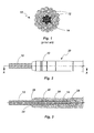
- Figure 1 is a cross-sectional view of an ACSR cable.
- Figure 2 is a side elevation view of a connector in accordance with an embodiment of the present invention installed on a cable.
- Figure 3 is a cross-sectional view through line A-A of the connector and cable shown in Figure 2 .
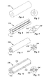
- Figure 4 is a perspective view of a first type of connector insert.
- Figure 5 is an end view of the connector insert shown in Figure 4 .
- Figure 6 is a perspective view of a second type of connector insert.
- Figure 7 is an end view of the connector insert shown in Figure 6 .
- Figure 8 is a perspective view of a third type of connector insert.
- Figure 9 is an end view of the connector insert shown in Figure 8 .
- Figure 10 is a perspective view of a fourth type of connector insert.
- Figure 11 is an end view of the connector insert shown in Figure 10 .
- Figure 12 is a cross-sectional view of the connector body shown in Figure 2 .
- Figure 13 illustrates the swaging regions on the connector body.
- Figure 14 is a cross sectional view of a connector body in accordance with another embodiment of the invention.
- the invention is described with reference to an ACSR cable; however, the invention is also applicable to ACSS, ACSS/AW, ACSS/TW, ACAR, ACCC and other reinforced cables having a load-carrying core surrounded by conductor strands.
- the core may comprise steel, high-strength aluminum alloys or composite materials, whereas the conductor strands may comprise aluminum, copper or alloys thereof.
- FIG. 1 A common type of ACSR cable 10 is illustrated in Figure 1 .
- This particular type of cable having an industry designation 26/7, has twenty-six outer strands of aluminum conductor 12 surrounding a core 14 comprising seven strands of steel.
- the steel core is a primary contributor to the tensile strength of cable 10.
- a connector 20 in accordance with one embodiment of the present invention is shown in Figures 2 and 3 .
- the connector body 22 has a substantially cylindrical outer surface and has a bored-out central cavity 24 extending from the proximal end 26 to an annular seating surface 28.
- a connector insert 30 is inserted into cavity 24 and rests against seating surface 28.
- the aluminum strands at the end of cable 10 are removed for a distance approximately equal to the length of the connector insert.
- the end of cable 10 is inserted into cavity 24 with the steel core 14 fitting into a central axial bore in the connector insert 30 and the cut-back ends of the aluminum strands enclosed within the proximal portion of cavity 24. Once assembled in this fashion, the connector 20 is secured to the end of cable 10 with multiple swages as described below.
- Connector 20 may be configured either as a splice connector with a tubular body receiving a cable at each end or as a full tension dead end having a suitable structural coupling, such as an eye or clevis, at the distal end of the body. Alternatively, a dead end structural coupling may be incorporated in the connector insert.
- Connector body 22 may be fabricated with a suitable aluminum alloy, such as 3003-H18.
- Connector insert 30 may be configured as a simple tubular body 300 as illustrated in Figures 4 and 5 or may be configured in accordance with one of several other designs.
- One such design is illustrated in Figures 6 and 7 .
- Connector insert 310 is configured as a tube with a central axial bore 312 and, in cross-section, spokes 314 radiating outwardly from an annular region 316 surrounding the central bore.
- Another connector insert design is illustrated in Figures 8 and 9 .
- Connector insert 320 is configured as a tube with a central axial bore 322 and, in cross-section, spokes 324 radiating inwardly from circular outer portion 326.
- Yet another connector insert design is illustrated in Figures 10 and 11 .
- Connector insert 330 is generally tubular in configuration with a central axial bore 332 and a plurality of axially extending slots 334 similar to a collet chuck.
- the scope of the invention is not limited to these particular configurations.
- Other configurations of connector inserts may be employed to serve the purpose of gripping the core of the cable when the connector body is swaged around the connector insert.
- the connector insert may have aluminum oxide or other suitable grit bonded onto the inner surface of the axial bore to increase the mechanical grip on the core of the cable.
- the inner surface of the axial bore may be machined with female threads, circumferential teeth or other surface finishes to enhance the connector insert's grip on the core of the cable.
- the connector insert rather than the connector body, may incorporate the structural coupling of a dead end connector, such as an eye or clevis.
- the connector insert may be fabricated with suitable aluminum or steel alloys, such as 6061-T6 aluminum or tool steel.
- Figure 12 is a cross-sectional view of connector body 22 illustrating its internal structure.
- cavity 24 In portion A of the connector body, where the connector insert is inserted, cavity 24 has a diameter d 1 , which is only slightly larger than the outer diameter of the connector insert. Moving from portion A towards the proximal end 26 of the connector body, the diameter of the cavity is increased in steps. Each such step transfers a different compression force to the cable and serves to distribute the swaging load to all of the aluminum strand layers in the ACSR cable.
- Portion B of cavity 24, which is proximally adjacent to portion A, has a diameter d 2 . As illustrated here, d 2 is larger than d 1 . However, portion B may have the same diameter as portion A.
- Portion C of cavity 24, which is proximally adjacent to portion B has a diameter d 3 , which is larger than d 2 . Additional proximally displaced portions of cavity 24 may have further stepped-up diameters. The number of steps may be fewer or greater than illustrated in the figures and will generally be determined by the size of the cable.
- the outer connector body is swaged at several locations to secure it uniformly around the aluminum strands of the cable and around the connector insert that grips the steel strands of the cable.
- the swaging operation is preferably performed using the 360° Radial Swage Tool manufactured by DMC Power, Inc. of Gardena, California.
- the connector body is swaged within portion A to secure the connector insert and the steel core of the cable. Multiple overlapped swages may be needed to fully secure the cable insert.
- the connector body is also swaged within portions B and C to secure the aluminum conductor strands. The compression ratio and the compression stress are increased approximately 3% to 20% at each portion as the internal diameter of the connector body decreases.
- D There is a space or gap, denoted as D, between any consecutive swages on the aluminum strands.
- This space in the range of about 0.1" to 0.5", allows the aluminum strands to flare out behind each swage and lock the cable behind the swage when it is subjected to tensile force. Additionally, there is a gap D2 between the swages in portions A and B, which also allows the conductor strands to flare out.
- the swage in portion A securing the connector insert and the steel core of the cable disposed therein has the primary function of transmitting the tensile load of the cable through the connector, whereas the swages in portions B and C (and any additional portions with further stepped up internal diameters) add to the tensile strength, but also serve the function of establishing electrical conductivity between the cable and the connector. Since the outer connector body has a uniform diameter, only a single die is required to swage the connector body in each of portions A, B and C.
- connector 20 may also be attached to the cable using two dies with a somewhat different sequence of steps.
- the connector insert which in this case may be a simple tube as shown in Figures 4 and 5 , may first be swaged onto the cable core with a smaller die sized to the outer diameter of the insert. Then, the connector body may be swaged onto the connector insert and cable conductors with a larger die sized to the outer diameter of the connector body. In this case, the conductor strands at the end of cable 10 are first removed for a distance approximately equal to the length of the connector insert as described above.
- the exposed core at the end of cable 10 is inserted into the central axial bore in the connector insert 30 and a suitably sized die is used to swage the connector insert onto the cable core.
- the connector insert is then inserted into cavity 24 of connector body 22 until it abuts seating surface 28.
- the connector body is then swaged onto the connector insert and the conductor strands of the cable as previously described.
- Figure 14 is a cross-sectional view of a connector body 220 in accordance with another embodiment of the invention. Whereas the internal cavity 24 of connector body 22 is stepped, cavity 240 of connector body 220 is tapered from d 1 to d 4 in portion E. This configuration also results in each swage applied to the connector body within portion E transferring a different compression ratio and compression stress to the cable as a function of the internal diameter at each swage location so as to distribute the swaging load to all of the conductor strand layers in the cable.
Abstract
Description
- This invention relates to the field of electrical power transmission and, more particularly, to full tension connectors for reinforced cables having a load-carrying core surrounded by conductor strands, which are used in electrical substations and high-tension power transmission lines.
- High-capacity, high-strength reinforced stranded cables are typically used in overhead power lines. An example of such a cable is Aluminum Conductor, Steel Reinforced (ACSR). In ACSR, the outer strands are aluminum, chosen for its excellent conductivity, low weight and low cost. The outer strands surround one or more center strands of steel, which provide the strength required to support the weight of the cable without stretching the ductile aluminum conductor strands. This gives the cable an overall higher tensile strength compared to a cable composed of only aluminum conductor strands. Other types of reinforced cable having a load-carrying core surrounded by conductor strands include, but are not limited to, Aluminum Conductor, Steel Supported (ACSS), Aluminum-Clad Steel Supported (ACSS/AW), Aluminum Conductor, Steel Supported (Trapezoidal Shaped Aluminum Strands) (ACSS/TW), Aluminum Conductor Aluminum Alloy Reinforced (ACAR) and Aluminum Conductor Composite Core (ACCC).
- Connectors play a critical role in the efficiency and reliability of power transmission systems. Cables used for overhead transmission lines require connectors for splices and dead end assemblies. Commonly assigned
U.S. Patent No. 7,874,881 discloses a full tension fitting for all-aluminum cables. While this fitting could be used with reinforced cables having a load-carrying core surrounded by conductor strands, the resulting connection would not withstand the same high tensile load that the cable itself is designed to withstand. Connectors for reinforced cables typically comprise a two-part assembly with a connector body and an insert or core grip. The insert is first fastened to the cable core and then the connector body is fastened to the insert and to the cable conductors. For swaged connectors, this requires two different sized dies. - The present invention provides an improved cable connector with an insert having an axial bore dimensioned to receive the core of the cable. A connector body has a substantially cylindrical outer surface and a substantially cylindrical cavity. A distal portion of the cavity having a first substantially cylindrical inner surface is dimensioned to receive the connector insert. A second portion of the cavity proximally displaced from the distal portion has a substantially cylindrical second inner surface dimensioned to receive the conductor strands of the cable. The connector body may be configured with one or more additional portions of the cavity having substantially cylindrical inner surfaces with progressively increasing diameters, the number of such portions depending on the size of the cable. Alternatively, the inner surface of the cavity may have a slight taper. Using a single die, the connector body is compressed with a swaging tool at several axially spaced-apart locations to grip the conductor strands and also to compress the connector insert, thereby gripping the core of the cable. Alternatively, using two different dies, the connector core may be compressed after the core of the cable is inserted, but before the connector core is inserted into the connector body.
- The invention also relates to a method of attaching the connector to an electrical cable having a core surrounded by connector strands comprising: removing a portion of the conductor strands proximate to an end of the cable to expose a corresponding portion of the cable core; inserting the exposed portion of the cable core into the bore in the connector insert; inserting the end of the cable into the cavity of the connector body such that the connector insert is inserted into the distal portion of the cavity in the connector body and the conductor strands are inserted into the second portion of the cavity; compressing the outer surface of the connector body surrounding the distal portion of the cavity with at least a first compression force; compressing the outer surface of the connector body surrounding the second portion of the cavity with a second compression force; compressing the outer surface of the connector body surrounding the third portion of the cavity with a third compression force. Preferably the steps of compressing the outer surface of the connector body are performed using a swaging tool. Preferably the method further comprises, before inserting the end of the cable into the cavity of the connector body, compressing the connector insert to engage the portion of the cable core inserted into the connector insert. Preferably the step of compressing the connector insert is performed using a swaging tool.
-
Figure 1 is a cross-sectional view of an ACSR cable. -
Figure 2 is a side elevation view of a connector in accordance with an embodiment of the present invention installed on a cable. -
Figure 3 is a cross-sectional view through line A-A of the connector and cable shown inFigure 2 . -
Figure 4 is a perspective view of a first type of connector insert. -
Figure 5 is an end view of the connector insert shown inFigure 4 . -
Figure 6 is a perspective view of a second type of connector insert. -
Figure 7 is an end view of the connector insert shown inFigure 6 . -
Figure 8 is a perspective view of a third type of connector insert. -
Figure 9 is an end view of the connector insert shown inFigure 8 . -
Figure 10 is a perspective view of a fourth type of connector insert. -
Figure 11 is an end view of the connector insert shown inFigure 10 . -
Figure 12 is a cross-sectional view of the connector body shown inFigure 2 . -
Figure 13 illustrates the swaging regions on the connector body. -
Figure 14 is a cross sectional view of a connector body in accordance with another embodiment of the invention. - In the following description, for purposes of explanation and not limitation, specific details are set forth in order to provide a thorough understanding of the present invention. However, it will be apparent to one skilled in the art that the present invention may be practiced in other embodiments that depart from these specific details. In other instances, detailed descriptions of well-known methods and devices are omitted so as to not obscure the description of the present invention with unnecessary detail.
- The invention is described with reference to an ACSR cable; however, the invention is also applicable to ACSS, ACSS/AW, ACSS/TW, ACAR, ACCC and other reinforced cables having a load-carrying core surrounded by conductor strands. The core may comprise steel, high-strength aluminum alloys or composite materials, whereas the conductor strands may comprise aluminum, copper or alloys thereof.
- A common type of ACSR
cable 10 is illustrated inFigure 1 . This particular type of cable, having anindustry designation 26/7, has twenty-six outer strands ofaluminum conductor 12 surrounding acore 14 comprising seven strands of steel. As explained above, the steel core is a primary contributor to the tensile strength ofcable 10. - A
connector 20 in accordance with one embodiment of the present invention is shown inFigures 2 and 3 . Theconnector body 22 has a substantially cylindrical outer surface and has a bored-outcentral cavity 24 extending from theproximal end 26 to anannular seating surface 28. Aconnector insert 30 is inserted intocavity 24 and rests againstseating surface 28. The aluminum strands at the end ofcable 10 are removed for a distance approximately equal to the length of the connector insert. The end ofcable 10 is inserted intocavity 24 with thesteel core 14 fitting into a central axial bore in the connector insert 30 and the cut-back ends of the aluminum strands enclosed within the proximal portion ofcavity 24. Once assembled in this fashion, theconnector 20 is secured to the end ofcable 10 with multiple swages as described below. -
Connector 20 may be configured either as a splice connector with a tubular body receiving a cable at each end or as a full tension dead end having a suitable structural coupling, such as an eye or clevis, at the distal end of the body. Alternatively, a dead end structural coupling may be incorporated in the connector insert.Connector body 22 may be fabricated with a suitable aluminum alloy, such as 3003-H18. -
Connector insert 30 may be configured as a simpletubular body 300 as illustrated inFigures 4 and 5 or may be configured in accordance with one of several other designs. One such design is illustrated inFigures 6 and 7 .Connector insert 310 is configured as a tube with a centralaxial bore 312 and, in cross-section,spokes 314 radiating outwardly from anannular region 316 surrounding the central bore. Another connector insert design is illustrated inFigures 8 and 9 .Connector insert 320 is configured as a tube with a centralaxial bore 322 and, in cross-section,spokes 324 radiating inwardly from circularouter portion 326. Yet another connector insert design is illustrated inFigures 10 and 11 .Connector insert 330 is generally tubular in configuration with a centralaxial bore 332 and a plurality of axially extendingslots 334 similar to a collet chuck. The scope of the invention is not limited to these particular configurations. Other configurations of connector inserts may be employed to serve the purpose of gripping the core of the cable when the connector body is swaged around the connector insert. The connector insert may have aluminum oxide or other suitable grit bonded onto the inner surface of the axial bore to increase the mechanical grip on the core of the cable. Alternatively, the inner surface of the axial bore may be machined with female threads, circumferential teeth or other surface finishes to enhance the connector insert's grip on the core of the cable. Furthermore, the connector insert, rather than the connector body, may incorporate the structural coupling of a dead end connector, such as an eye or clevis. The connector insert may be fabricated with suitable aluminum or steel alloys, such as 6061-T6 aluminum or tool steel. -
Figure 12 is a cross-sectional view ofconnector body 22 illustrating its internal structure. In portion A of the connector body, where the connector insert is inserted,cavity 24 has a diameter d1, which is only slightly larger than the outer diameter of the connector insert. Moving from portion A towards theproximal end 26 of the connector body, the diameter of the cavity is increased in steps. Each such step transfers a different compression force to the cable and serves to distribute the swaging load to all of the aluminum strand layers in the ACSR cable. Portion B ofcavity 24, which is proximally adjacent to portion A, has a diameter d2. As illustrated here, d2 is larger than d1. However, portion B may have the same diameter as portion A. Portion C ofcavity 24, which is proximally adjacent to portion B has a diameter d3, which is larger than d2. Additional proximally displaced portions ofcavity 24 may have further stepped-up diameters. The number of steps may be fewer or greater than illustrated in the figures and will generally be determined by the size of the cable. - Referring now to
Figure 13 , after the cable and connector insert have been inserted intocavity 24, the outer connector body is swaged at several locations to secure it uniformly around the aluminum strands of the cable and around the connector insert that grips the steel strands of the cable. The swaging operation is preferably performed using the 360° Radial Swage Tool manufactured by DMC Power, Inc. of Gardena, California. The connector body is swaged within portion A to secure the connector insert and the steel core of the cable. Multiple overlapped swages may be needed to fully secure the cable insert. The connector body is also swaged within portions B and C to secure the aluminum conductor strands. The compression ratio and the compression stress are increased approximately 3% to 20% at each portion as the internal diameter of the connector body decreases. There is a space or gap, denoted as D, between any consecutive swages on the aluminum strands. This space, in the range of about 0.1" to 0.5", allows the aluminum strands to flare out behind each swage and lock the cable behind the swage when it is subjected to tensile force. Additionally, there is a gap D2 between the swages in portions A and B, which also allows the conductor strands to flare out. The swage in portion A securing the connector insert and the steel core of the cable disposed therein has the primary function of transmitting the tensile load of the cable through the connector, whereas the swages in portions B and C (and any additional portions with further stepped up internal diameters) add to the tensile strength, but also serve the function of establishing electrical conductivity between the cable and the connector. Since the outer connector body has a uniform diameter, only a single die is required to swage the connector body in each of portions A, B and C. - As with prior art connectors for reinforced cables,
connector 20 may also be attached to the cable using two dies with a somewhat different sequence of steps. The connector insert, which in this case may be a simple tube as shown inFigures 4 and 5 , may first be swaged onto the cable core with a smaller die sized to the outer diameter of the insert. Then, the connector body may be swaged onto the connector insert and cable conductors with a larger die sized to the outer diameter of the connector body. In this case, the conductor strands at the end ofcable 10 are first removed for a distance approximately equal to the length of the connector insert as described above. The exposed core at the end ofcable 10 is inserted into the central axial bore in theconnector insert 30 and a suitably sized die is used to swage the connector insert onto the cable core. The connector insert is then inserted intocavity 24 ofconnector body 22 until it abuts seatingsurface 28. The connector body is then swaged onto the connector insert and the conductor strands of the cable as previously described. -
Figure 14 is a cross-sectional view of aconnector body 220 in accordance with another embodiment of the invention. Whereas theinternal cavity 24 ofconnector body 22 is stepped,cavity 240 ofconnector body 220 is tapered from d1 to d4 in portion E. This configuration also results in each swage applied to the connector body within portion E transferring a different compression ratio and compression stress to the cable as a function of the internal diameter at each swage location so as to distribute the swaging load to all of the conductor strand layers in the cable. - It will be recognized that the above-described invention may be embodied in other specific forms without departing from the spirit or essential characteristics of the disclosure. Thus, it is understood that the invention is not to be limited by the foregoing illustrative details, but rather is to be defined by the appended claims.
Claims (15)
- A connector for an electrical cable having a core surrounded by conductor strands comprising:a connector insert having an axial bore dimensioned to receive the core of the cable;a connector body having an opening at a proximal end thereof and a substantially cylindrical outer surface, the opening communicating with a cavity having a distal portion dimensioned to receive the connector insert, said distal portion having a first inner surface with a first inside diameter, said cavity further having a second portion proximally displaced from the distal portion having a second inner surface with a second inside diameter dimensioned to receive the conductor strands, wherein the second inside diameter is greater than the first inside diameter.
- The connector of claim 1 wherein the cavity further has a third portion proximally adjacent to the second portion having a third inner surface with a third inside diameter, wherein the third inside diameter is greater than the second inside diameter.
- The connector of claim 1 wherein the cavity is stepped between the first and second inner surfaces.
- The connector of claim 1 wherein the cavity is tapered between the first and second inner surfaces.
- The connector of claim 1 wherein the connector body is configured as a splice.
- The connector of claim 1 wherein the connector body is configured as a dead end.
- The connector of claim 1 wherein an axial cross-section of the connector insert has a plurality of spokes radiating outwardly from an annular region surrounding the bore.
- The connector of claim 1 wherein an axial cross-section of the connector insert has a plurality of spokes radiating inwardly from a circular outer perimeter.
- The connector of claim 1 wherein the connector insert is generally tubular with a plurality of axially extending slots.
- The connector of claim 1 wherein the connector insert is configured as a dead end eye.
- The connector of claim 1 wherein the connector insert is configured as a dead end clevis.
- A method of attaching the connector of claim 1 to an electrical cable having a core surrounded by conductor strands comprising:removing a portion of the conductor strands proximate to an end of the cable to expose a corresponding portion of the cable core;inserting the exposed portion of the cable core into the bore in the connector insert;inserting the end of the cable into the cavity of the connector body such that the connector insert is inserted into the distal portion of the cavity in the connector body and the conductor strands are inserted into the second portion of the cavity;compressing the outer surface of the connector body surrounding the distal portion of the cavity with at least a first compression force;compressing the outer surface of the connector body surrounding the second portion of the cavity with a second compression force.
- The method of claim 12 wherein the steps of compressing the outer surface of the connector body are performed using a swaging tool.
- The method of claim 12 further comprising, before inserting the end of the cable into the cavity of the connector body, of compressing the connector insert to engage the portion of the cable core inserted into the connector insert.
- The method of claim 14 wherein the step of compressing the connector insert is performed using a swaging tool.
Priority Applications (4)
| Application Number | Priority Date | Filing Date | Title |
|---|---|---|---|
| PL12177292T PL2560239T3 (en) | 2011-08-15 | 2012-07-20 | Method of attaching a connector to an electrical cable |
| SI201231654T SI2560239T1 (en) | 2011-08-15 | 2012-07-20 | Method of attaching a connector to an electrical cable |
| RSP20191069 RS59151B1 (en) | 2011-08-15 | 2012-07-20 | Method of attaching a connector to an electrical cable |
| HRP20191453 HRP20191453T1 (en) | 2011-08-15 | 2019-08-09 | Method of attaching a connector to an electrical cable |
Applications Claiming Priority (3)
| Application Number | Priority Date | Filing Date | Title |
|---|---|---|---|
| US201161523530P | 2011-08-15 | 2011-08-15 | |
| US13/274,503 US20130043072A1 (en) | 2011-08-15 | 2011-10-17 | Full tension swaged acsr connector |
| US13/413,473 US9166303B2 (en) | 2011-08-15 | 2012-03-06 | Full tension swaged connector for reinforced cable |
Publications (3)
| Publication Number | Publication Date |
|---|---|
| EP2560239A2 true EP2560239A2 (en) | 2013-02-20 |
| EP2560239A3 EP2560239A3 (en) | 2014-12-03 |
| EP2560239B1 EP2560239B1 (en) | 2019-05-22 |
Family
ID=46650371
Family Applications (1)
| Application Number | Title | Priority Date | Filing Date |
|---|---|---|---|
| EP12177292.5A Active EP2560239B1 (en) | 2011-08-15 | 2012-07-20 | Method of attaching a connector to an electrical cable |
Country Status (6)
| Country | Link |
|---|---|
| US (1) | US9166303B2 (en) |
| EP (1) | EP2560239B1 (en) |
| CA (1) | CA2778681C (en) |
| PL (1) | PL2560239T3 (en) |
| RS (1) | RS59151B1 (en) |
| SI (1) | SI2560239T1 (en) |
Families Citing this family (5)
| Publication number | Priority date | Publication date | Assignee | Title |
|---|---|---|---|---|
| JP6324164B2 (en) * | 2013-12-17 | 2018-05-16 | 日新製鋼株式会社 | Composite stranded wire |
| US9748670B1 (en) * | 2016-12-01 | 2017-08-29 | Afl Telecommunications Llc | Conductor connector accessories and methods for connecting conductors to conductor connector accessories |
| CN107613592A (en) * | 2017-10-31 | 2018-01-19 | 山东华宁电伴热科技有限公司 | One kind series connection high-power connectivity kit of heating tape |
| CN112166285A (en) | 2018-05-07 | 2021-01-01 | 杜罗达尼公司 | Eyelet assembly |
| US11217915B2 (en) * | 2018-06-19 | 2022-01-04 | Preformed Line Products Co. | Composite core conductor compression connectors and methods for using same |
Citations (1)
| Publication number | Priority date | Publication date | Assignee | Title |
|---|---|---|---|---|
| US7874881B1 (en) | 2009-08-14 | 2011-01-25 | Designed Metal Connections, Inc. | Full tension swaged connector |
Family Cites Families (41)
| Publication number | Priority date | Publication date | Assignee | Title |
|---|---|---|---|---|
| US3125630A (en) | 1964-03-17 | Electrical connector | ||
| US1886086A (en) * | 1927-09-29 | 1932-11-01 | American Brass Co | Connecter for cables |
| US1909344A (en) | 1930-02-24 | 1933-05-16 | Roeblings John A Sons Co | Attachment for wire ropes |
| US2188178A (en) | 1938-09-16 | 1940-01-23 | Gen Electric | Connector for sector conductor cables |
| US2799721A (en) | 1953-01-09 | 1957-07-16 | Amp Inc | Connector |
| US2958723A (en) | 1957-10-02 | 1960-11-01 | Thomas & Betts Corp | Electrical connector and sealing means therefor |
| US3052750A (en) | 1959-09-15 | 1962-09-04 | Amp Inc | High tensile splice |
| US3033600A (en) | 1960-05-04 | 1962-05-08 | Drysdale John | Connectors for jointing wires, rods and the like |
| GB954409A (en) | 1962-01-09 | 1964-04-08 | Cable Covers Ltd | Compression connectors for joining or terminating wires, rods and other suitable members |
| US3996417A (en) | 1974-09-12 | 1976-12-07 | Aluminum Company Of America | Cable core grip, electrical cable and connector assembly, and electrical connector kit |
| GB1493713A (en) | 1974-09-12 | 1977-11-30 | Aluminum Co Of America | Electrical connectors and multi-strand cables and method of using the same |
| US3976385A (en) | 1974-10-09 | 1976-08-24 | Raychem Corporation | Method and apparatus for splicing lines |
| FR2509919A1 (en) | 1981-07-15 | 1983-01-21 | Dervaux Ets | ANCHORING OR JUNCTION SLEEVE |
| US4453034A (en) | 1981-12-30 | 1984-06-05 | Fargo Mfg. Company, Inc. | One die system of compression transmission fittings |
| US4817682A (en) | 1984-12-17 | 1989-04-04 | Houston Industries, Incorporated | Splicing tool for transmission lines |
| US4681382A (en) | 1985-12-20 | 1987-07-21 | Amp Incorporated | Electrical connector for transmission cable |
| US5516158A (en) | 1986-07-18 | 1996-05-14 | Watts; John D. | Self-swaging threaded tubular connection |
| US4829146A (en) | 1988-04-11 | 1989-05-09 | Amerace Corporation | Metallic coupling system |
| US5069058A (en) | 1988-12-27 | 1991-12-03 | Deutsch Metal Components | Swaging tool |
| JPH0584135A (en) | 1991-09-27 | 1993-04-06 | Mitsubishi Electric Home Appliance Co Ltd | Rice cooking apparatus |
| JPH05155980A (en) | 1991-12-05 | 1993-06-22 | Kansai Paint Co Ltd | Water-base dispersion |
| US6015953A (en) | 1994-03-11 | 2000-01-18 | Tohoku Electric Power Co., Inc. | Tension clamp for stranded conductor |
| JPH07250418A (en) | 1994-03-11 | 1995-09-26 | Tohoku Electric Power Co Inc | Anchor end part for stranded wire |
| US5654527A (en) | 1994-07-19 | 1997-08-05 | The Deutsch Company | Method and apparatus for connecting electric bus |
| US5600096A (en) | 1994-09-27 | 1997-02-04 | The Whitaker Corporation | Mechanical connector splice for cable |
| US5821463A (en) | 1996-06-14 | 1998-10-13 | The Whitaker Corporation | Mechanical connector splice for cable |
| JPH11187524A (en) | 1997-12-18 | 1999-07-09 | Sanwa Tekki Corp | Aluminum sleeve for wire anchoring clamp and wire protective member |
| US6165004A (en) | 1998-05-26 | 2000-12-26 | Robinson; Philip A. | Power line connector/tap splice apparatus |
| JP2002216864A (en) | 2001-01-19 | 2002-08-02 | Yazaki Corp | Connection structure and connection method of electric cable |
| US7595455B2 (en) * | 2002-02-21 | 2009-09-29 | Wayne H. Robinson | Kenny clamp |
| CA2556907C (en) | 2004-02-24 | 2013-10-29 | Lokring Technology Corporation | Hydraulic hand tool |
| US7305749B2 (en) * | 2004-08-04 | 2007-12-11 | Kramer James M | Wire terminal crimper |
| US7311553B2 (en) | 2004-11-16 | 2007-12-25 | Hubbell Incorporated | Compression connector assembly |
| US7049520B1 (en) | 2005-03-15 | 2006-05-23 | Hubbell Incorporated | Connector for splicing cables |
| US7299674B2 (en) | 2005-05-09 | 2007-11-27 | Designed Metal Connections | Swaging tool |
| US7531747B2 (en) | 2005-08-03 | 2009-05-12 | Hubbell Incorporated | Energy directing unitized core grip for electrical connector |
| US7342175B2 (en) | 2005-09-19 | 2008-03-11 | Fci Americas Technology, Inc. | Electrical connector |
| US7353602B2 (en) | 2006-03-07 | 2008-04-08 | 3M Innovative Properties Company | Installation of spliced electrical transmission cables |
| US7394022B2 (en) | 2006-07-27 | 2008-07-01 | Markus Gumley | Electrical wire connector with temporary grip |
| US8246393B2 (en) | 2007-03-12 | 2012-08-21 | Hubbell Incorporated | Implosion connector and method for use with transmission line conductors comprising composite cores |
| JP5155980B2 (en) | 2009-10-23 | 2013-03-06 | 三菱重工業株式会社 | Turbo compound system and operation method thereof |
-
2012
- 2012-03-06 US US13/413,473 patent/US9166303B2/en active Active
- 2012-05-31 CA CA2778681A patent/CA2778681C/en active Active
- 2012-07-20 PL PL12177292T patent/PL2560239T3/en unknown
- 2012-07-20 RS RSP20191069 patent/RS59151B1/en unknown
- 2012-07-20 SI SI201231654T patent/SI2560239T1/en unknown
- 2012-07-20 EP EP12177292.5A patent/EP2560239B1/en active Active
Patent Citations (1)
| Publication number | Priority date | Publication date | Assignee | Title |
|---|---|---|---|---|
| US7874881B1 (en) | 2009-08-14 | 2011-01-25 | Designed Metal Connections, Inc. | Full tension swaged connector |
Also Published As
| Publication number | Publication date |
|---|---|
| CA2778681A1 (en) | 2013-02-15 |
| EP2560239A3 (en) | 2014-12-03 |
| RS59151B1 (en) | 2019-10-31 |
| EP2560239B1 (en) | 2019-05-22 |
| SI2560239T1 (en) | 2019-09-30 |
| US20130043073A1 (en) | 2013-02-21 |
| PL2560239T3 (en) | 2019-10-31 |
| US9166303B2 (en) | 2015-10-20 |
| CA2778681C (en) | 2014-11-04 |
Similar Documents
| Publication | Publication Date | Title |
|---|---|---|
| US6805596B2 (en) | Compression formed connector for a composite conductor assembly used in transmission line installations and method of constructing the same | |
| US7342175B2 (en) | Electrical connector | |
| EP2560239B1 (en) | Method of attaching a connector to an electrical cable | |
| US7874881B1 (en) | Full tension swaged connector | |
| EP1935071B1 (en) | Electrical connector | |
| US4453034A (en) | One die system of compression transmission fittings | |
| AU2012202914B2 (en) | Full tension swaged connector for reinforced cable | |
| US9748670B1 (en) | Conductor connector accessories and methods for connecting conductors to conductor connector accessories | |
| US20130043072A1 (en) | Full tension swaged acsr connector | |
| US10637166B1 (en) | Modular conductor connector assemblies and connecting methods | |
| CA2765395C (en) | Full tension swaged connector | |
| EP3926759B1 (en) | Cable assembly and method of joining cables | |
| US9698497B2 (en) | Repair sleeve | |
| EP3787122B1 (en) | Device for interconnecting cables |
Legal Events
| Date | Code | Title | Description |
|---|---|---|---|
| PUAI | Public reference made under article 153(3) epc to a published international application that has entered the european phase |
Free format text: ORIGINAL CODE: 0009012 |
|
| 17P | Request for examination filed |
Effective date: 20120720 |
|
| AK | Designated contracting states |
Kind code of ref document: A2 Designated state(s): AL AT BE BG CH CY CZ DE DK EE ES FI FR GB GR HR HU IE IS IT LI LT LU LV MC MK MT NL NO PL PT RO RS SE SI SK SM TR |
|
| AX | Request for extension of the european patent |
Extension state: BA ME |
|
| PUAL | Search report despatched |
Free format text: ORIGINAL CODE: 0009013 |
|
| AK | Designated contracting states |
Kind code of ref document: A3 Designated state(s): AL AT BE BG CH CY CZ DE DK EE ES FI FR GB GR HR HU IE IS IT LI LT LU LV MC MK MT NL NO PL PT RO RS SE SI SK SM TR |
|
| AX | Request for extension of the european patent |
Extension state: BA ME |
|
| RIC1 | Information provided on ipc code assigned before grant |
Ipc: H01R 4/62 20060101ALI20141024BHEP Ipc: H01R 4/20 20060101ALI20141024BHEP Ipc: H01R 4/18 20060101AFI20141024BHEP |
|
| RBV | Designated contracting states (corrected) |
Designated state(s): AL AT BE BG CH CY CZ DE DK EE ES FI FR GB GR HR HU IE IS IT LI LT LU LV MC MK MT NL NO PL PT RO RS SE SI SK SM TR |
|
| STAA | Information on the status of an ep patent application or granted ep patent |
Free format text: STATUS: EXAMINATION IS IN PROGRESS |
|
| 17Q | First examination report despatched |
Effective date: 20170503 |
|
| GRAP | Despatch of communication of intention to grant a patent |
Free format text: ORIGINAL CODE: EPIDOSNIGR1 |
|
| STAA | Information on the status of an ep patent application or granted ep patent |
Free format text: STATUS: GRANT OF PATENT IS INTENDED |
|
| INTG | Intention to grant announced |
Effective date: 20181219 |
|
| GRAS | Grant fee paid |
Free format text: ORIGINAL CODE: EPIDOSNIGR3 |
|
| GRAA | (expected) grant |
Free format text: ORIGINAL CODE: 0009210 |
|
| STAA | Information on the status of an ep patent application or granted ep patent |
Free format text: STATUS: THE PATENT HAS BEEN GRANTED |
|
| AK | Designated contracting states |
Kind code of ref document: B1 Designated state(s): AL AT BE BG CH CY CZ DE DK EE ES FI FR GB GR HR HU IE IS IT LI LT LU LV MC MK MT NL NO PL PT RO RS SE SI SK SM TR |
|
| REG | Reference to a national code |
Ref country code: GB Ref legal event code: FG4D |
|
| REG | Reference to a national code |
Ref country code: CH Ref legal event code: EP |
|
| REG | Reference to a national code |
Ref country code: IE Ref legal event code: FG4D |
|
| REG | Reference to a national code |
Ref country code: DE Ref legal event code: R096 Ref document number: 602012060303 Country of ref document: DE |
|
| REG | Reference to a national code |
Ref country code: AT Ref legal event code: REF Ref document number: 1137230 Country of ref document: AT Kind code of ref document: T Effective date: 20190615 |
|
| REG | Reference to a national code |
Ref country code: CH Ref legal event code: NV Representative=s name: ARNOLD AND SIEDSMA AG, CH |
|
| REG | Reference to a national code |
Ref country code: NL Ref legal event code: FP |
|
| REG | Reference to a national code |
Ref country code: HR Ref legal event code: TUEP Ref document number: P20191453T Country of ref document: HR |
|
| REG | Reference to a national code |
Ref country code: RO Ref legal event code: EPE |
|
| REG | Reference to a national code |
Ref country code: DK Ref legal event code: T3 Effective date: 20190816 |
|
| RAP2 | Party data changed (patent owner data changed or rights of a patent transferred) |
Owner name: DMC POWER, INC. |
|
| REG | Reference to a national code |
Ref country code: SE Ref legal event code: TRGR |
|
| REG | Reference to a national code |
Ref country code: PT Ref legal event code: SC4A Ref document number: 2560239 Country of ref document: PT Date of ref document: 20190905 Kind code of ref document: T Free format text: AVAILABILITY OF NATIONAL TRANSLATION Effective date: 20190819 |
|
| REG | Reference to a national code |
Ref country code: NO Ref legal event code: T2 Effective date: 20190522 |
|
| REG | Reference to a national code |
Ref country code: EE Ref legal event code: FG4A Ref document number: E018007 Country of ref document: EE Effective date: 20190806 |
|
| REG | Reference to a national code |
Ref country code: HR Ref legal event code: ODRP Ref document number: P20191453T Country of ref document: HR Payment date: 20190821 Year of fee payment: 8 |
|
| REG | Reference to a national code |
Ref country code: HR Ref legal event code: T1PR Ref document number: P20191453 Country of ref document: HR |
|
| REG | Reference to a national code |
Ref country code: SK Ref legal event code: T3 Ref document number: E 32094 Country of ref document: SK |
|
| REG | Reference to a national code |
Ref country code: HU Ref legal event code: AG4A Ref document number: E045346 Country of ref document: HU |
|
| REG | Reference to a national code |
Ref country code: GR Ref legal event code: EP Ref document number: 20190402483 Country of ref document: GR Effective date: 20191128 |
|
| REG | Reference to a national code |
Ref country code: ES Ref legal event code: FG2A Ref document number: 2742828 Country of ref document: ES Kind code of ref document: T3 Effective date: 20200217 |
|
| REG | Reference to a national code |
Ref country code: DE Ref legal event code: R097 Ref document number: 602012060303 Country of ref document: DE |
|
| PLBE | No opposition filed within time limit |
Free format text: ORIGINAL CODE: 0009261 |
|
| STAA | Information on the status of an ep patent application or granted ep patent |
Free format text: STATUS: NO OPPOSITION FILED WITHIN TIME LIMIT |
|
| 26N | No opposition filed |
Effective date: 20200225 |
|
| REG | Reference to a national code |
Ref country code: HR Ref legal event code: ODRP Ref document number: P20191453 Country of ref document: HR Payment date: 20200703 Year of fee payment: 9 |
|
| REG | Reference to a national code |
Ref country code: HR Ref legal event code: ODRP Ref document number: P20191453 Country of ref document: HR Payment date: 20210705 Year of fee payment: 10 |
|
| REG | Reference to a national code |
Ref country code: AT Ref legal event code: UEP Ref document number: 1137230 Country of ref document: AT Kind code of ref document: T Effective date: 20190522 |
|
| PG25 | Lapsed in a contracting state [announced via postgrant information from national office to epo] |
Ref country code: AL Free format text: LAPSE BECAUSE OF FAILURE TO SUBMIT A TRANSLATION OF THE DESCRIPTION OR TO PAY THE FEE WITHIN THE PRESCRIBED TIME-LIMIT Effective date: 20190522 |
|
| REG | Reference to a national code |
Ref country code: HR Ref legal event code: ODRP Ref document number: P20191453 Country of ref document: HR Payment date: 20220711 Year of fee payment: 11 |
|
| REG | Reference to a national code |
Ref country code: HR Ref legal event code: ODRP Ref document number: P20191453 Country of ref document: HR Payment date: 20230704 Year of fee payment: 12 |
|
| PGFP | Annual fee paid to national office [announced via postgrant information from national office to epo] |
Ref country code: NL Payment date: 20230726 Year of fee payment: 12 Ref country code: LU Payment date: 20230727 Year of fee payment: 12 |
|
| PGFP | Annual fee paid to national office [announced via postgrant information from national office to epo] |
Ref country code: TR Payment date: 20230707 Year of fee payment: 12 Ref country code: SM Payment date: 20230706 Year of fee payment: 12 Ref country code: RO Payment date: 20230707 Year of fee payment: 12 Ref country code: NO Payment date: 20230727 Year of fee payment: 12 Ref country code: MC Payment date: 20230706 Year of fee payment: 12 Ref country code: IT Payment date: 20230720 Year of fee payment: 12 Ref country code: IE Payment date: 20230727 Year of fee payment: 12 Ref country code: GB Payment date: 20230727 Year of fee payment: 12 Ref country code: FI Payment date: 20230725 Year of fee payment: 12 Ref country code: ES Payment date: 20230804 Year of fee payment: 12 Ref country code: EE Payment date: 20230703 Year of fee payment: 12 Ref country code: CZ Payment date: 20230711 Year of fee payment: 12 Ref country code: CY Payment date: 20230706 Year of fee payment: 12 Ref country code: CH Payment date: 20230802 Year of fee payment: 12 Ref country code: BG Payment date: 20230720 Year of fee payment: 12 Ref country code: AT Payment date: 20230705 Year of fee payment: 12 |
|
| PGFP | Annual fee paid to national office [announced via postgrant information from national office to epo] |
Ref country code: SK Payment date: 20230703 Year of fee payment: 12 Ref country code: SI Payment date: 20230705 Year of fee payment: 12 Ref country code: SE Payment date: 20230727 Year of fee payment: 12 Ref country code: RS Payment date: 20230706 Year of fee payment: 12 Ref country code: PT Payment date: 20230703 Year of fee payment: 12 Ref country code: PL Payment date: 20230703 Year of fee payment: 12 Ref country code: IS Payment date: 20230711 Year of fee payment: 12 Ref country code: HU Payment date: 20230713 Year of fee payment: 12 Ref country code: HR Payment date: 20230704 Year of fee payment: 12 Ref country code: GR Payment date: 20230727 Year of fee payment: 12 Ref country code: FR Payment date: 20230725 Year of fee payment: 12 Ref country code: DK Payment date: 20230727 Year of fee payment: 12 Ref country code: DE Payment date: 20230727 Year of fee payment: 12 Ref country code: BE Payment date: 20230727 Year of fee payment: 12 |
|
| PGFP | Annual fee paid to national office [announced via postgrant information from national office to epo] |
Ref country code: MT Payment date: 20230704 Year of fee payment: 12 Ref country code: LV Payment date: 20230712 Year of fee payment: 12 Ref country code: LT Payment date: 20230703 Year of fee payment: 12 |
|
| PGFP | Annual fee paid to national office [announced via postgrant information from national office to epo] |
Ref country code: AL Payment date: 20230715 Year of fee payment: 12 |
|
| PGFP | Annual fee paid to national office [announced via postgrant information from national office to epo] |
Ref country code: MK Payment date: 20230704 Year of fee payment: 12 |