EP2560068A1 - Apparatus and methods for moving an input interface relative to a display of an electronic device - Google Patents
Apparatus and methods for moving an input interface relative to a display of an electronic device Download PDFInfo
- Publication number
- EP2560068A1 EP2560068A1 EP11177635A EP11177635A EP2560068A1 EP 2560068 A1 EP2560068 A1 EP 2560068A1 EP 11177635 A EP11177635 A EP 11177635A EP 11177635 A EP11177635 A EP 11177635A EP 2560068 A1 EP2560068 A1 EP 2560068A1
- Authority
- EP
- European Patent Office
- Prior art keywords
- input interface
- display
- electronic device
- input
- area
- Prior art date
- Legal status (The legal status is an assumption and is not a legal conclusion. Google has not performed a legal analysis and makes no representation as to the accuracy of the status listed.)
- Withdrawn
Links
Images


Classifications
-
- G—PHYSICS
- G06—COMPUTING; CALCULATING OR COUNTING
- G06F—ELECTRIC DIGITAL DATA PROCESSING
- G06F1/00—Details not covered by groups G06F3/00 - G06F13/00 and G06F21/00
- G06F1/16—Constructional details or arrangements
- G06F1/1613—Constructional details or arrangements for portable computers
- G06F1/1615—Constructional details or arrangements for portable computers with several enclosures having relative motions, each enclosure supporting at least one I/O or computing function
- G06F1/1622—Constructional details or arrangements for portable computers with several enclosures having relative motions, each enclosure supporting at least one I/O or computing function with enclosures rotating around an axis perpendicular to the plane they define or with ball-joint coupling, e.g. PDA with display enclosure orientation changeable between portrait and landscape by rotation with respect to a coplanar body enclosure
-
- G—PHYSICS
- G06—COMPUTING; CALCULATING OR COUNTING
- G06F—ELECTRIC DIGITAL DATA PROCESSING
- G06F1/00—Details not covered by groups G06F3/00 - G06F13/00 and G06F21/00
- G06F1/16—Constructional details or arrangements
- G06F1/1613—Constructional details or arrangements for portable computers
- G06F1/1633—Constructional details or arrangements of portable computers not specific to the type of enclosures covered by groups G06F1/1615 - G06F1/1626
- G06F1/1684—Constructional details or arrangements related to integrated I/O peripherals not covered by groups G06F1/1635 - G06F1/1675
- G06F1/169—Constructional details or arrangements related to integrated I/O peripherals not covered by groups G06F1/1635 - G06F1/1675 the I/O peripheral being an integrated pointing device, e.g. trackball in the palm rest area, mini-joystick integrated between keyboard keys, touch pads or touch stripes
- G06F1/1692—Constructional details or arrangements related to integrated I/O peripherals not covered by groups G06F1/1635 - G06F1/1675 the I/O peripheral being an integrated pointing device, e.g. trackball in the palm rest area, mini-joystick integrated between keyboard keys, touch pads or touch stripes the I/O peripheral being a secondary touch screen used as control interface, e.g. virtual buttons or sliders
-
- H—ELECTRICITY
- H04—ELECTRIC COMMUNICATION TECHNIQUE
- H04M—TELEPHONIC COMMUNICATION
- H04M1/00—Substation equipment, e.g. for use by subscribers
- H04M1/02—Constructional features of telephone sets
- H04M1/0202—Portable telephone sets, e.g. cordless phones, mobile phones or bar type handsets
- H04M1/0206—Portable telephones comprising a plurality of mechanically joined movable body parts, e.g. hinged housings
- H04M1/0208—Portable telephones comprising a plurality of mechanically joined movable body parts, e.g. hinged housings characterized by the relative motions of the body parts
- H04M1/0225—Rotatable telephones, i.e. the body parts pivoting to an open position around an axis perpendicular to the plane they define in closed position
- H04M1/0231—Including a rotatable keypad body part
-
- H—ELECTRICITY
- H04—ELECTRIC COMMUNICATION TECHNIQUE
- H04M—TELEPHONIC COMMUNICATION
- H04M1/00—Substation equipment, e.g. for use by subscribers
- H04M1/02—Constructional features of telephone sets
- H04M1/0202—Portable telephone sets, e.g. cordless phones, mobile phones or bar type handsets
- H04M1/0206—Portable telephones comprising a plurality of mechanically joined movable body parts, e.g. hinged housings
- H04M1/0208—Portable telephones comprising a plurality of mechanically joined movable body parts, e.g. hinged housings characterized by the relative motions of the body parts
- H04M1/0225—Rotatable telephones, i.e. the body parts pivoting to an open position around an axis perpendicular to the plane they define in closed position
- H04M1/0233—Including a rotatable display body part
-
- H—ELECTRICITY
- H04—ELECTRIC COMMUNICATION TECHNIQUE
- H04M—TELEPHONIC COMMUNICATION
- H04M2250/00—Details of telephonic subscriber devices
- H04M2250/16—Details of telephonic subscriber devices including more than one display unit
Definitions
- the present disclosure relates to electronic devices, including but not limited to, apparatus and methods for moving an input interface relative to a display of an electronic device.
- Portable electronic devices include, for example, several types of mobile stations such as simple cellular telephones, smart telephones, wireless personal digital assistants (PDAs), and laptop computers with wireless 802.11 or Bluetooth capabilities.
- PIM personal information manager
- Portable electronic devices such as PDAs or smart telephones are generally intended for handheld use and ease of portability. Smaller devices are generally desirable for portability.
- a touch-sensitive display also known as a touch-screen display, is particularly useful on handheld devices, which are small and have limited space for user input and output.
- the information displayed on the touch-sensitive displays may be modified depending on the functions and operations being performed. With continued demand for decreased size of portable electronic devices, touch-sensitive displays continue to decrease in size.
- some electronic devices often include an input interface (e.g., a keypad) to input commands or information to the electronic device.
- the input interface or keypad pivots, flips or slides relative to the touch-sensitive display.
- a user can typically only access the input interface when the input interface is in one state relative to the display.
- an input interface e.g., a keypad
- a closed position a user cannot access the input interface and, instead, can only interact with the electronic device via the touch-sensitive display.
- FIG. 1 is a block diagram of an electronic device in accordance with the disclosure.
- FIG. 2A is a perspective view of the example electronic device of FIG. 1 shown in a first position.
- FIG. 2B is a front view of the example electronic device of FIG. 2A .
- FIG. 2C is a side view of the example electronic device of FIG. 2B .
- FIG. 3A is a perspective view of the example electronic device of FIG. 1 shown in a second position.
- FIG. 3B is a front view of the example electronic device of FIG. 3A .
- FIG. 3C is a side view of the example electronic device of FIG. 3B .
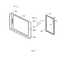
- FIG. 4 is an exploded view of the example electronic device of FIG. 1 , FIGS. 2A-2C and FIGS. 3A-3C .
- FIG. 5 shows an input device of the example electronic device swiveling relative to a display of the electronic device.
- FIG. 6 shows the electronic device of FIG. 1 and FIGS. 2A-2C in a landscape orientation and the input interface in a first user mode.
- FIG. 7 shows the electronic device of FIG. 1 and FIGS. 3A-3C in a landscape orientation and the input interface in a second user mode.
- the disclosure generally relates to electronic devices such as, for example, a portable electronic device in the examples described herein.
- portable electronic devices include mobile, or handheld, wireless communication devices such as pagers, cellular phones, cellular smart-phones, wireless organizers, personal digital assistants, wirelessly enabled notebook computers, tablet computers and so forth.
- the portable electronic device may also be a portable electronic device without wireless communication capabilities, such as a handheld electronic game device, digital photograph album, digital camera, or other device.
- an example electronic device described herein provides a low-profile, compact or smaller viewing area when the electronic device is in a first physical state or position (e.g., a closed position) and an expanded or larger viewing area when the electronic device is in a second physical state or position (e.g., an open position).
- the electronic devices described herein provide a low-profile, compact electronic device having a compact viewing area when the electronic device is in the first position (e.g., a compact state) while having the capability to expand and provide a larger viewing area when the electronic device is in the second position (e.g., an expanded state).
- the example electronic devices described herein employ a movable input interface or input area.
- the input interface swivels or pivots relative to a display between a first user mode position and a second user mode position that corresponds to the respective compact and expanded positions of the electronic device.
- a movable input interface e.g., a slider phone, a flip phone, etc.
- the input interface of the example electronic devices described herein is accessible for use when the electronic device is in an open condition or position and a closed position or condition.
- the input interface includes an input area on a first surface of the input interface and a second surface opposite the first surface.
- a pivot mount is disposed between the second surface of the input interface and a housing of the display.
- the second surface of the input interface is oriented toward the display and is oriented toward the display as the input interface pivots between the first and second positions.
- the input area of the input interface is disposed or extends over at least a portion of the pivot mount to maximize a surface area of the input area.
- the input interface may include physical keys (e.g., depressible keys, plastic keys, etc.) and in other examples the input interface may include a touch screen display that may present an image of keys (e.g., numerical, alphanumerical, control keys, etc.) to a user.
- the assigned functionality of the input interface when in the first user mode and the assigned functionality of the input interface when in the second user mode may be adjusted such that a user input(s) (e.g., characters, numerals, etc.) available in the first user mode may be different (e.g., have their functionality reassigned, reoriented, flipped and/or otherwise adjusted) when the electronic device moves between the first and second user modes.
- the input interface may include a morphing keypad that presents a QWERTY key set when the input interface is in the first user mode and presents a SureType key set when the input interface is in a second user mode.
- FIG. 1 A block diagram of an example portable electronic device 100 is shown in FIG. 1 .
- the portable electronic device 100 includes multiple components, such as a processor 102 that controls the overall operation of the portable electronic device 100. Communication functions, including data and voice communications, are performed through a communication subsystem 104. Data received by the portable electronic device 100 is decompressed and decrypted by a decoder 106. The communication subsystem 104 receives messages from and sends messages to a wireless network 108.
- the wireless network 108 may be any type of wireless network, including, but not limited to, data wireless networks, voice wireless networks, and networks that support both voice and data communications.
- a power source 110 such as one or more rechargeable batteries or a port to an external power supply, powers the portable electronic device 100.
- the processor 102 interacts with other components, such as Random Access Memory (RAM) 112, memory 114, a display 116 with a touch-sensitive overlay 118 operably connected to an electronic controller 120 that together comprise a first touch-sensitive display 122, an auxiliary input/output (I/O) subsystem 124, a data port 126, a speaker 128, a microphone 130, short-range communications 132, and other device subsystems 134.
- RAM Random Access Memory
- memory 114 a display 116 with a touch-sensitive overlay 118 operably connected to an electronic controller 120 that together comprise a first touch-sensitive display 122, an auxiliary input/output (I/O) subsystem 124, a data port 126, a speaker 128, a microphone 130, short-range communications 132, and other device subsystems 134.
- I/O auxiliary input/output
- data port 126 a data port 126
- speaker 1208 a speaker
- microphone 130 a microphone 130
- short-range communications 132 short-
- Information such as text, characters, symbols, images, icons, and other items that may be displayed or rendered on a portable electronic device, is displayed on the touch-sensitive display 122 via the processor 102.
- the processor 102 may interact with an accelerometer 136 that may be utilized to detect direction of gravitational forces or gravity-induced reaction forces.
- the processor 102 interacts with an input device or input interface 138.
- the input device or input interface 138 may be, for example, a second display 140 with a touch-sensitive overlay 142 operably connected to the electronic controller 144 that together comprise a second touch-sensitive display 146. User-interaction with a graphical user interface may be performed through the second touch-sensitive overlay 146.
- the processor 102 interacts with the touch-sensitive overlay 142 via the electronic controller 144.
- Information such as text, characters, symbols, images, icons, and other items that may be displayed or rendered on a portable electronic device, is displayed on the touch-sensitive display 146 via the processor 102.
- the input device or interface 138 may be a keypad 148 such as, for example, a dome-switch keypad, an electronic keypad, a morphing keypad or any other suitable keypad as described in greater detail below.
- the portable electronic device 100 uses a Subscriber Identity Module or a Removable User Identity Module (SIM/RUIM) card 150 for communication with a network, such as the wireless network 108.
- SIM/RUIM Removable User Identity Module
- user identification information may be programmed into memory 114.
- the portable electronic device 100 includes an operating system 152 and software programs or components 154 that are executed by the processor 102 and are typically stored in a persistent, updatable store such as the memory 114. Additional applications or programs may be loaded onto the portable electronic device 100 through the wireless network 108, the auxiliary I/O subsystem 124, the data port 126, the short-range communications subsystem 132, or any other suitable subsystem 134.
- a received signal such as a text message, an e-mail message, or web page download is processed by the communication subsystem 104 and input to the processor 102.
- the processor 102 processes the received signal for output to the display 116 and/or to the auxiliary I/O subsystem 124.
- a subscriber may generate data items, for example e-mail messages, which may be transmitted over the wireless network 108 through the communication subsystem 104.
- the speaker 128 outputs audible information converted from electrical signals
- the microphone 130 converts audible information into electrical signals for processing.
- the touch-sensitive displays 122 and/or 146 may be any suitable touch-sensitive display, such as a capacitive, resistive, infrared, surface acoustic wave (SAW) touch-sensitive display, strain gauge, optical imaging, dispersive signal technology, acoustic pulse recognition, and so forth, as known in the art.
- a capacitive touch-sensitive display includes a capacitive touch-sensitive overlay.
- the overlay may be an assembly of multiple layers in a stack including, for example, a substrate, a ground shield layer, a barrier layer, one or more capacitive touch sensor layers separated by a substrate or other barrier, and a cover.
- the capacitive touch sensor layers may be any suitable material, such as patterned indium tin oxide (ITO).
- FIG. 2A is a perspective view of an example mobile electronic device 100 of FIG. 1 shown in a first physical state 200 such as a closed position.
- FIG. 2B is a front view of the example electronic device 100 shown in FIG. 2A.
- FIG. 2C is a side view of the example electronic device 100 shown in FIG. 2A and FIG. 2B .
- the portable electronic device 100 is a handheld communication device or a mobile device such as a mobile phone.
- the electronic device 100 may be a data and/or voice-enabled handheld device that may be used to send and receive a message, a voice communication, a textual entry, etc.
- the electronic device 100 may provide a variety of functions including, for example, telephonic, electronic messaging, and other personal information manager (PIM) application functions.
- PIM personal information manager
- the electronic device 100 includes a first portion 202 to support the touch-screen display 122 that is coupled to a second portion 204 to support the input interface 138.
- the input interface 138 is in a first user mode or position 206 such that the second portion 204 is positioned generally partially over the first portion 202 of the electronic device 100.
- the input interface 138 is substantially aligned with the display 122 to cover at least a portion 208 ( FIG. 2C ) of the touch-screen display 122 to provide a first viewing area 210 of the touch screen display 122 when the electronic device 100 is in the closed position 200 as shown in FIGS.
- the viewing area 210 is defined by an area 212 of the touch screen display 122 that is visible to a user when the electronic device 100 is in the first position 200.
- the viewing area 210 may also include an input area 214 defined by the input interface 138.
- a user may have access to, and/or interact with the electronic device 100 via the area 212 of the touch-screen display 122 and the user input area 214 defined by the input interface 138.
- the area 212 of the display 122 may present graphical displays and the input area 214 of the input interface 138 may present a numerical key set, a QWERTY key set, a SureType key set, and/or any other suitable key sets or input controls such as multimedia input key sets having functions to control media content or a media application.
- the input interface 138 effectively expands the touch-screen display 122 such that an image or graphical representation (e.g., a website) is transposed across both the area 212 of the touch-screen display 122 and the area 214 of the input interface 138.
- an image or graphical representation e.g., a website
- the first portion 202 of the electronic device 100 includes a first housing 216 that encloses the electronic or mobile components described above in connection with FIG. 1 .
- the first housing 216 encloses the microprocessor 102, the speaker 128, the microphone 130, the accelerometer 136, etc.
- the first housing 216 of the illustrated example can be held in one hand by a user of the electronic device 100 during data (e.g., text) and/or voice communications.
- the first housing 216 of the electronic device 100 includes an upper housing portion or lid 218 and a lower housing portion or base 220.
- the base 220 includes lateral sides 222a, 222b, top and bottom sides 224a, 224b and a rear or back side 226 ( FIG. 2C ).
- the lid 218 retains the touch-screen display 122 within the base 220 such that the lid 218 and the touch-screen display 122 define a front side 228 of the housing 216.
- the electronic device 100 includes a graphical user interface 230 (GUI) controlled by, for example, the operating system 152 ( FIG. 1 ).
- GUI graphical user interface
- the GUI 230 is used to convey information and/or receive commands or information from a user, and includes a variety of GUI objects or controls that include, for example, apps, icons, toolbars, drop-down menus, pop-up menus, text, dialog boxes, buttons, etc.
- the GUI 230 provides a window 232 in which a user may view a menu item (i.e., an icon), an application (e.g., an app) and/or a document.
- a user can interact with the GUI 230 via the touch-screen display 122.
- the second portion 204 of the electronic device 100 is a second housing 234 that receives or houses the input interface or input device 138.
- the second housing 234 includes a lid 236 that couples to a base 238 to capture or restrain the input interface 138 within the base 238.
- lateral sides 240a, 240b of the second housing 234 and/or the input interface 138 are substantially aligned with the respective lateral sides 222a, 222b of the housing 216 and/or the touch screen display 122.
- the touch-screen display 122 provides a portrait orientation
- the input interface 138 provides a landscape orientation.
- the input interface 138 has a width substantially similar or equal to a width of the touch-screen display 122 when the input interface 138 is in the landscape orientation and the touch-screen display 122 is in the portrait orientation.
- the input interface 138 may be the touch-screen display 146. Additionally, the touch-screen display 146 may provide a second graphical user interface 242 (GUI) controlled by, for example, the operating system 152 ( FIG. 1 ). For example, the touch-screen display 146 may present an image of keys or characters 244 (e.g., alphanumerical, numerical, etc.) to a user of the electronic device 100.
- the input interface 138 may include the physical keypad 148 that presents keys or characters 244a.
- the keypad 148 may be a dome-switch keypad or any other suitable keypad and may present a QWERTY style key set, a SureType style key set and/or any other suitable key set or control key sets as described below.
- FIG. 3A is a perspective view of the example electronic device 100 of FIG. 1 shown in a second physical state 300 such as an open position.
- FIG. 3B is a front view of the example electronic device 100 of FIG. 3A.
- FIG. 3C is a side view of the example electronic device 100 of FIG. 3A and FIG. 3B .
- the second portion 204 is positioned away from the first portion 202 of the electronic device 100 to a second user mode or position 302.
- the input interface 138 uncovers or exposes the portion 208 ( FIG. 3C ) of the touch-screen display 122 to provide a second viewing area 304 of the touch-screen display 122.
- a larger viewing area 304 is visible to a user of the electronic device 100 when the input interface 138 is in the second user mode 302.
- the viewing area 304 is defined by an exposed area 306 of the touch-screen display 122.
- the viewing area 304 may also be defined by the input area 214 of the input interface 138.
- a user of the electronic device 100 may have access to and/or interact with the electronic device 100 via the area 306 of the touch-screen display 122 and the input area 214 defined by the input interface 138.
- the lateral sides 240a, 240b of the housing 234 and/or the input interface 138 are substantially aligned with the respective lateral sides 222a, 222b of the first housing 216 and/or the touch-screen display 122.
- the touch-screen display 122 provides a portrait orientation
- the user interface 138 provides a landscape orientation.
- the input interface 138 has a width substantially similar to the width of the touch-screen display 122 when the input interface 138 is in the second position 302.
- the graphical user interface 230 adjusts, expands or otherwise provides a window 310 in which a user may view a menu item (i.e., an icon), an application (e.g., an app), a document, etc.
- a menu item i.e., an icon
- an application e.g., an app
- the area 306 may present graphical displays, applications, etc.
- the input area 214 may present a numerical key set, a QWERTY key set, a SureType key set, and/or any other suitable key sets or input controls such as multimedia input keys each having a function to control media content or a media application.
- the input interface 138 may be the touch-screen display 146 or, alternatively, may be physical keys provided by the keypad 148 (e.g., a dome-switch keypad).
- the touch-screen display 146 may present one or more characters 244 to enable a user to input information and/or command the electronic device 100.
- the assigned functionality of the input area 214 in the first user mode 206 and the assigned functionality of the input area 214 in the second user mode 302 may be adjusted such that the user input(s) available in the first user mode 206 may have their functionality reassigned or adjusted when the input interface 138 swivels between the first and second user modes 206 and 302.
- the input interface 214 may present one or more characters or control inputs 244, 244a (e.g., a QWERTY type keypad, either virtual or physical keys).
- characters or control inputs 244, 244a e.g., a QWERTY type keypad, either virtual or physical keys.
- the input interface 138 when the input interface 138 is swiveled between the first user mode 206 and the second user mode 302, the input interface 138 changes or reverses orientation to provide one or more characters or control inputs 310.
- the input interface 138 is capable of reorienting the one or more characters or controls 244, 244a to the orientation of the one or more characters or controls 310.
- the touch-screen display 146 flips (or provides a mirror image of) a virtual QWERTY key set about a horizontal axis 312.
- the physical keypad may be a morphing keypad that presents or appears as a standard alphanumeric keypad when a phone application of the electronic device 100 is activated, morphs to present or appear as a music control keypad when a multimedia application of the electronic device is activated, morphs to present or appear as a camera function key set like zoom and video when a camera application of the electronic device is activated, etc.
- the physical keypad may be configured to reorient or flip the physical keys when the input interface 138 swivels between the first and second user modes 206 and 302.
- each key of the keypad 148 may be assigned dual function.
- a key of a keypad represents the character "T" in a QWERTY key set when the input interface 138 is in the first user mode 206 and the same key represents the character "B" in a QWERTY key set when the input interface 138 is in the second user mode 302.
- the input interface 138 uncovers or exposes the portion 208 of the touch-screen display 122 to effectively expand a user viewing area such that an image or graphical representation (e.g., a website) is transposed across both the area 306 of the touch-screen display 122 and the input area 214 of the input interface 138.
- an image or graphical representation e.g., a website
- the input interface 138 moves or swivels relative to the touch-screen display 122 between the first user mode 206 to provide the first viewing area 210 and the second user mode 302 to provide the second viewing area 304, where the first viewing area 210 is smaller than the second viewing area 304. Additionally, the input interface 138 is accessible to a user when the input interface 138 is in either the first user mode 206 or the second user mode 302.
- FIG. 4 is an exploded view of the example electronic device 100 of FIG. 1 , FIGS. 2A-2C , and FIGS. 3A-3C .
- the electronic device 100 employs a pivot mount or pivot apparatus 400.
- the pivot apparatus 400 of the illustrated example is a pivot pin 402, which enables the input interface 138 to move, swivel or pivot relative to the touch-screen display 122.
- the pivot pin 402 is disposed between a side 404 of the housing 216 and a side or surface 406 of the user interface 138 opposite the input area 214.
- the housing 216 includes an opening 408 to receive a first end 410 of the pivot pin 402 and the housing 234 or surface 406 includes an opening or recess (not shown) to receive a second end 412 of the pivot pin 402.
- the pivot mount 400 does not extend through the housing 234.
- the input area 214 of the input interface 138 is disposed over at least a portion of the pivot mount 400 to maximize a surface area 414 of the input interface 138 and, thus, the input area 214.
- the input area 214 substantially covers, hides, conceals, overlaps or otherwise extends over at least a portion of the pivot mount 400.
- the pivot apparatus 400, the housing 216 and/or the housing 234 may include a first position stop and a second position stop to limit pivotal or swivel movement of the input interface 138 relative to the housing 216 between the respective first and second user modes 206 and 302.
- the stops may limit the rotational, swivel or pivotal range of the input interface 138 relative to the touch-screen display 122 through approximately 180 degrees.
- FIG. 5 illustrates the electronic device 100 of FIG. 1 , FIGS. 2A-2C , and FIGS. 3A-3C in an intermediate state 500 between the closed and open positions 200 and 300.
- the input interface 138 swivels relative to the touch-screen display 122 about a pivot or swivel axis 502 defined by the pivot pin 402.
- the pivot pin 402 enables the input interface 138 to swivel relative to the housing 216 about the swivel axis 502 between the first user mode 206 to cover the portion 208 of the touch-screen display 122 and the second user mode 302 to expose the portion 208 of the touch-screen display 122.
- the input interface 138 extends over at least a portion of the swivel axis 502 such that the swivel axis 502 intersects or is substantially perpendicular to the input area 214. As shown in FIG. 5 , the input interface 138 is coupled to the housing 216 such that a face 504 and/or the input area 214 of the user interface 138 is oriented substantially similar or parallel relative to a face 506 of the touch-screen display 122 when the input interface 138 pivots or swivels between the first and second user modes 206 and 302.
- the surface 406 of the input interface 138 is oriented toward the surface 404 of the housing 216 when the input interface 138 pivots relative to the display between the first and second positions 206 and 302.
- the input area 214 is oriented relative to the face 506 of the touch-screen display 122 such that the input area 214 of the input interface 138 is user accessible when the input interface 138 is in the first user mode 206 and the second user mode 302.
- the pivot pin 402 is positioned adjacent an edge 508 of the housing 216 and an edge 510 of the housing 234 and approximately at a midpoint 512 between respective lateral edges 222a, 222b of the housing 216 and the lateral edges 240a, 240b of the housing 234.
- the edges 508 and 510 are substantially perpendicular relative to the respective lateral edges 222a, 222b, 240a and 240b.
- the pivot pin 402 is aligned substantially along a longitudinal axis 514 of the housing 216.
- the longitudinal axis 514 extends between the top side 224a of the housing 216 and the bottom side 224b of the housing 216 and passes through the midpoint 512 between the first and second lateral sides 222a, 222b of the housing 216.
- the electronic device 100 includes a sensor or switch 516 that provides a signal to the processor 102 to detect the physical state of the electronic device 100 (e.g., when the electronic device 100 is in the closed position 200 or the open position 300). For example, the sensor 516 generates an open or close signal according to the position of the input interface 138 relative to the housing 216.
- the processor 102 processes the signal(s) received from the sensor 516 and determines if the input interface 138 is in the first user mode 206 or the second user mode 302.
- the sensor or switch 516 may include, but is not limited to, a Hall sensor, an optical sensor, an electromagnetic switch, a contact switch, a mechanical switch, etc.
- FIG. 6 illustrates the example electronic device 100 in a landscape orientation 600 when the input interface 138 is in the first user mode 206.
- the touch-screen display 122 presents a landscape orientation and the input interface 138 presents a portrait orientation.
- the input interface 138 shown in FIG. 6 may present a SureType key set 602 when the input interface 138 is in the portrait orientation of FIG. 6 .
- the input interface 138 may present different key sets regardless of whether the input interface 138 is the touch-screen display 146 or the physical keypad 148.
- the electronic device 100 may sense such a rotation via, for example, the accelerometer 136 and may command or control (e.g., the GFI of) the input interface 138 to display or present the SureType key set 602 and/or any other key set.
- the accelerometer 136 may command or control (e.g., the GFI of) the input interface 138 to display or present the SureType key set 602 and/or any other key set.
- FIG. 7 illustrates the electronic device 100 in a landscape orientation and the input interface 138 in the second user mode 302.
- the GUI 230 of the touch-screen display 122 may present an application and the input interface 138 may present controls for the application.
- the touch-screen display 122 may present a multimedia or music player application and the input interface 138 may present control keys 702 to control the media such as, for example, skip 704, play 706, pause 708, etc.
- the touch screen-display 122 may present a first application and the input interface 138 may present a second application.
- the touch screen-display 122 may present an internet application to enable a user to surf the internet and the input interface 138 may present a multimedia or music player application to enable a user to play music, an email application, etc.
- the example electronic device described herein provides a first viewing area in a first mode of operation to provide a compact electronic device, while providing a second viewing area larger than the first viewing area in a second mode of operation.
- an input interface or input area is accessible to a user when the electronic device is in either the first mode of operation or the second mode of operation.
- Such a configuration enables a user to interact with the electronic device when the electronic device is in the first mode of operation (a compact mode) or the second mode of operation (an expanded mode).
- the user interface may be configured to provide or present different key sets or configurations (e.g., morphing key sets) depending on an activated application of the electronic device 100.
- the methods described herein may be carried out by software executed, for example, by the processor 102. Coding of software for carrying out such a method is within the scope of a person of ordinary skill in the art given the present description.
- a computer-readable medium having computer-readable code may be executed by at least one processor of the portable electronic device 100 to perform the methods described herein.
Abstract
Description
- The present disclosure relates to electronic devices, including but not limited to, apparatus and methods for moving an input interface relative to a display of an electronic device.
- Electronic devices, including portable electronic devices, have gained widespread use and may provide a variety of functions including, for example, telephonic, electronic messaging, and other personal information manager (PIM) application functions. Portable electronic devices include, for example, several types of mobile stations such as simple cellular telephones, smart telephones, wireless personal digital assistants (PDAs), and laptop computers with wireless 802.11 or Bluetooth capabilities.
- Portable electronic devices such as PDAs or smart telephones are generally intended for handheld use and ease of portability. Smaller devices are generally desirable for portability. A touch-sensitive display, also known as a touch-screen display, is particularly useful on handheld devices, which are small and have limited space for user input and output. The information displayed on the touch-sensitive displays may be modified depending on the functions and operations being performed. With continued demand for decreased size of portable electronic devices, touch-sensitive displays continue to decrease in size.
- In addition to the touch-sensitive display, some electronic devices often include an input interface (e.g., a keypad) to input commands or information to the electronic device. In some examples, the input interface or keypad pivots, flips or slides relative to the touch-sensitive display. As a result, a user can typically only access the input interface when the input interface is in one state relative to the display. For example, an input interface (e.g., a keypad) can pivot relative to a display of an electronic device between an open position at which the input interface is accessible and a closed position at which the input interface is not accessible. Thus, in the closed position, a user cannot access the input interface and, instead, can only interact with the electronic device via the touch-sensitive display.
-
FIG. 1 is a block diagram of an electronic device in accordance with the disclosure. -
FIG. 2A is a perspective view of the example electronic device ofFIG. 1 shown in a first position. -
FIG. 2B is a front view of the example electronic device ofFIG. 2A . -
FIG. 2C is a side view of the example electronic device ofFIG. 2B . -
FIG. 3A is a perspective view of the example electronic device ofFIG. 1 shown in a second position. -
FIG. 3B is a front view of the example electronic device ofFIG. 3A . -
FIG. 3C is a side view of the example electronic device ofFIG. 3B . -
FIG. 4 is an exploded view of the example electronic device ofFIG. 1 ,FIGS. 2A-2C andFIGS. 3A-3C . -
FIG. 5 . shows an input device of the example electronic device swiveling relative to a display of the electronic device. -
FIG. 6 shows the electronic device ofFIG. 1 andFIGS. 2A-2C in a landscape orientation and the input interface in a first user mode. -
FIG. 7 shows the electronic device ofFIG. 1 andFIGS. 3A-3C in a landscape orientation and the input interface in a second user mode. - The disclosure generally relates to electronic devices such as, for example, a portable electronic device in the examples described herein. Examples of portable electronic devices include mobile, or handheld, wireless communication devices such as pagers, cellular phones, cellular smart-phones, wireless organizers, personal digital assistants, wirelessly enabled notebook computers, tablet computers and so forth. The portable electronic device may also be a portable electronic device without wireless communication capabilities, such as a handheld electronic game device, digital photograph album, digital camera, or other device.
- In general, an example electronic device described herein provides a low-profile, compact or smaller viewing area when the electronic device is in a first physical state or position (e.g., a closed position) and an expanded or larger viewing area when the electronic device is in a second physical state or position (e.g., an open position). As a result, the electronic devices described herein provide a low-profile, compact electronic device having a compact viewing area when the electronic device is in the first position (e.g., a compact state) while having the capability to expand and provide a larger viewing area when the electronic device is in the second position (e.g., an expanded state).
- To provide the compact and expanded states, the example electronic devices described herein employ a movable input interface or input area. The input interface swivels or pivots relative to a display between a first user mode position and a second user mode position that corresponds to the respective compact and expanded positions of the electronic device. Unlike known electronic devices that utilize a movable input interface (e.g., a slider phone, a flip phone, etc.) that is only accessible for use when the electronic device is in only one position (e.g., an open position), the input interface of the example electronic devices described herein is accessible for use when the electronic device is in an open condition or position and a closed position or condition.
- For example, the input interface includes an input area on a first surface of the input interface and a second surface opposite the first surface. A pivot mount is disposed between the second surface of the input interface and a housing of the display. In other words, the second surface of the input interface is oriented toward the display and is oriented toward the display as the input interface pivots between the first and second positions. Additionally, unlike many known devices, the input area of the input interface is disposed or extends over at least a portion of the pivot mount to maximize a surface area of the input area.
- In some examples, the input interface may include physical keys (e.g., depressible keys, plastic keys, etc.) and in other examples the input interface may include a touch screen display that may present an image of keys (e.g., numerical, alphanumerical, control keys, etc.) to a user. In either case, the assigned functionality of the input interface when in the first user mode and the assigned functionality of the input interface when in the second user mode may be adjusted such that a user input(s) (e.g., characters, numerals, etc.) available in the first user mode may be different (e.g., have their functionality reassigned, reoriented, flipped and/or otherwise adjusted) when the electronic device moves between the first and second user modes. With physical keys, this may be achieved by having multiple functions assigned to (and, in some cases, visible on) each key. For example, the input interface may include a morphing keypad that presents a QWERTY key set when the input interface is in the first user mode and presents a SureType key set when the input interface is in a second user mode.
- For simplicity and clarity of illustration, reference numerals may be repeated among the figures to indicate corresponding or analogous elements. Numerous details are set forth to provide an understanding of the embodiments described herein. The embodiments may be practiced without these details. In other instances, well-known methods, procedures, and components have not been described in detail to avoid obscuring the examples described. The description is not to be considered as limited to the scope of the examples described herein.
- A block diagram of an example portable
electronic device 100 is shown inFIG. 1 . The portableelectronic device 100 includes multiple components, such as aprocessor 102 that controls the overall operation of the portableelectronic device 100. Communication functions, including data and voice communications, are performed through acommunication subsystem 104. Data received by the portableelectronic device 100 is decompressed and decrypted by adecoder 106. Thecommunication subsystem 104 receives messages from and sends messages to awireless network 108. Thewireless network 108 may be any type of wireless network, including, but not limited to, data wireless networks, voice wireless networks, and networks that support both voice and data communications. Apower source 110, such as one or more rechargeable batteries or a port to an external power supply, powers the portableelectronic device 100. - The
processor 102 interacts with other components, such as Random Access Memory (RAM) 112,memory 114, adisplay 116 with a touch-sensitive overlay 118 operably connected to anelectronic controller 120 that together comprise a first touch-sensitive display 122, an auxiliary input/output (I/O)subsystem 124, adata port 126, aspeaker 128, amicrophone 130, short-range communications 132, andother device subsystems 134. In this example, user-interaction with a graphical user interface is performed through the touch-sensitive overlay 118. Theprocessor 102 interacts with the touch-sensitive overlay 118 via theelectronic controller 120. Information, such as text, characters, symbols, images, icons, and other items that may be displayed or rendered on a portable electronic device, is displayed on the touch-sensitive display 122 via theprocessor 102. Theprocessor 102 may interact with anaccelerometer 136 that may be utilized to detect direction of gravitational forces or gravity-induced reaction forces. - Additionally, the
processor 102 interacts with an input device orinput interface 138. The input device orinput interface 138 may be, for example, asecond display 140 with a touch-sensitive overlay 142 operably connected to theelectronic controller 144 that together comprise a second touch-sensitive display 146. User-interaction with a graphical user interface may be performed through the second touch-sensitive overlay 146. Theprocessor 102 interacts with the touch-sensitive overlay 142 via theelectronic controller 144. Information, such as text, characters, symbols, images, icons, and other items that may be displayed or rendered on a portable electronic device, is displayed on the touch-sensitive display 146 via theprocessor 102. Alternatively, the input device orinterface 138 may be akeypad 148 such as, for example, a dome-switch keypad, an electronic keypad, a morphing keypad or any other suitable keypad as described in greater detail below. - To identify a subscriber for network access, the portable
electronic device 100 uses a Subscriber Identity Module or a Removable User Identity Module (SIM/RUIM)card 150 for communication with a network, such as thewireless network 108. Alternatively, user identification information may be programmed intomemory 114. - The portable
electronic device 100 includes anoperating system 152 and software programs orcomponents 154 that are executed by theprocessor 102 and are typically stored in a persistent, updatable store such as thememory 114. Additional applications or programs may be loaded onto the portableelectronic device 100 through thewireless network 108, the auxiliary I/O subsystem 124, thedata port 126, the short-range communications subsystem 132, or any othersuitable subsystem 134. - A received signal such as a text message, an e-mail message, or web page download is processed by the
communication subsystem 104 and input to theprocessor 102. Theprocessor 102 processes the received signal for output to thedisplay 116 and/or to the auxiliary I/O subsystem 124. A subscriber may generate data items, for example e-mail messages, which may be transmitted over thewireless network 108 through thecommunication subsystem 104. For voice communications, the overall operation of the portableelectronic device 100 is similar. Thespeaker 128 outputs audible information converted from electrical signals, and themicrophone 130 converts audible information into electrical signals for processing. - The touch-
sensitive displays 122 and/or 146 may be any suitable touch-sensitive display, such as a capacitive, resistive, infrared, surface acoustic wave (SAW) touch-sensitive display, strain gauge, optical imaging, dispersive signal technology, acoustic pulse recognition, and so forth, as known in the art. A capacitive touch-sensitive display includes a capacitive touch-sensitive overlay. The overlay may be an assembly of multiple layers in a stack including, for example, a substrate, a ground shield layer, a barrier layer, one or more capacitive touch sensor layers separated by a substrate or other barrier, and a cover. The capacitive touch sensor layers may be any suitable material, such as patterned indium tin oxide (ITO). -
FIG. 2A is a perspective view of an example mobileelectronic device 100 ofFIG. 1 shown in a firstphysical state 200 such as a closed position.FIG. 2B is a front view of the exampleelectronic device 100 shown inFIG. 2A. FIG. 2C is a side view of the exampleelectronic device 100 shown inFIG. 2A and FIG. 2B . - In one example, the portable
electronic device 100 is a handheld communication device or a mobile device such as a mobile phone. As mentioned above, theelectronic device 100 may be a data and/or voice-enabled handheld device that may be used to send and receive a message, a voice communication, a textual entry, etc. Thus, theelectronic device 100 may provide a variety of functions including, for example, telephonic, electronic messaging, and other personal information manager (PIM) application functions. - Referring to
FIGS. 2A-2C , theelectronic device 100 includes afirst portion 202 to support the touch-screen display 122 that is coupled to asecond portion 204 to support theinput interface 138. As most clearly shown inFIG. 2B , when theelectronic device 100 is in theclosed position 200, theinput interface 138 is in a first user mode orposition 206 such that thesecond portion 204 is positioned generally partially over thefirst portion 202 of theelectronic device 100. In particular, theinput interface 138 is substantially aligned with thedisplay 122 to cover at least a portion 208 (FIG. 2C ) of the touch-screen display 122 to provide afirst viewing area 210 of thetouch screen display 122 when theelectronic device 100 is in theclosed position 200 as shown inFIGS. 2A-2C . In other words, a smaller, morecompact viewing area 210 is visible to a user when theinput interface 138 is in the first user mode orposition 206. Thus, theviewing area 210 is defined by anarea 212 of thetouch screen display 122 that is visible to a user when theelectronic device 100 is in thefirst position 200. In some examples, theviewing area 210 may also include aninput area 214 defined by theinput interface 138. - In the first
user mode position 206, a user may have access to, and/or interact with theelectronic device 100 via thearea 212 of the touch-screen display 122 and theuser input area 214 defined by theinput interface 138. For example, thearea 212 of thedisplay 122 may present graphical displays and theinput area 214 of theinput interface 138 may present a numerical key set, a QWERTY key set, a SureType key set, and/or any other suitable key sets or input controls such as multimedia input key sets having functions to control media content or a media application. In yet some examples, theinput interface 138 effectively expands the touch-screen display 122 such that an image or graphical representation (e.g., a website) is transposed across both thearea 212 of the touch-screen display 122 and thearea 214 of theinput interface 138. - The
first portion 202 of theelectronic device 100 includes afirst housing 216 that encloses the electronic or mobile components described above in connection withFIG. 1 . For example, thefirst housing 216 encloses themicroprocessor 102, thespeaker 128, themicrophone 130, theaccelerometer 136, etc. Thefirst housing 216 of the illustrated example can be held in one hand by a user of theelectronic device 100 during data (e.g., text) and/or voice communications. - The
first housing 216 of theelectronic device 100 includes an upper housing portion orlid 218 and a lower housing portion orbase 220. Thebase 220 includeslateral sides bottom sides FIG. 2C ). Thelid 218 retains the touch-screen display 122 within thebase 220 such that thelid 218 and the touch-screen display 122 define afront side 228 of thehousing 216. - To enable a user to interact with the
electronic device 100, theelectronic device 100 includes a graphical user interface 230 (GUI) controlled by, for example, the operating system 152 (FIG. 1 ). Generally, theGUI 230 is used to convey information and/or receive commands or information from a user, and includes a variety of GUI objects or controls that include, for example, apps, icons, toolbars, drop-down menus, pop-up menus, text, dialog boxes, buttons, etc. TheGUI 230 provides awindow 232 in which a user may view a menu item (i.e., an icon), an application (e.g., an app) and/or a document. For example, a user can interact with theGUI 230 via the touch-screen display 122. - In the illustrated example, the
second portion 204 of theelectronic device 100 is asecond housing 234 that receives or houses the input interface orinput device 138. Thesecond housing 234 includes alid 236 that couples to a base 238 to capture or restrain theinput interface 138 within thebase 238. In particular,lateral sides second housing 234 and/or theinput interface 138 are substantially aligned with the respectivelateral sides housing 216 and/or thetouch screen display 122. For example, when theelectronic device 100 is in a portrait orientation as shown inFIGS. 2A-2C , the touch-screen display 122 provides a portrait orientation and theinput interface 138 provides a landscape orientation. As shown, theinput interface 138 has a width substantially similar or equal to a width of the touch-screen display 122 when theinput interface 138 is in the landscape orientation and the touch-screen display 122 is in the portrait orientation. - In some examples, the
input interface 138 may be the touch-screen display 146. Additionally, the touch-screen display 146 may provide a second graphical user interface 242 (GUI) controlled by, for example, the operating system 152 (FIG. 1 ). For example, the touch-screen display 146 may present an image of keys or characters 244 (e.g., alphanumerical, numerical, etc.) to a user of theelectronic device 100. Alternatively, theinput interface 138 may include thephysical keypad 148 that presents keys or characters 244a. For example, thekeypad 148 may be a dome-switch keypad or any other suitable keypad and may present a QWERTY style key set, a SureType style key set and/or any other suitable key set or control key sets as described below. -
FIG. 3A is a perspective view of the exampleelectronic device 100 ofFIG. 1 shown in a secondphysical state 300 such as an open position.FIG. 3B is a front view of the exampleelectronic device 100 ofFIG. 3A. FIG. 3C is a side view of the exampleelectronic device 100 ofFIG. 3A and FIG. 3B . - As most clearly shown in
FIG. 3B , when theelectronic device 100 is in theopen position 300, thesecond portion 204 is positioned away from thefirst portion 202 of theelectronic device 100 to a second user mode orposition 302. In thesecond user mode 302, theinput interface 138 uncovers or exposes the portion 208 (FIG. 3C ) of the touch-screen display 122 to provide asecond viewing area 304 of the touch-screen display 122. In other words, alarger viewing area 304 is visible to a user of theelectronic device 100 when theinput interface 138 is in thesecond user mode 302. Theviewing area 304 is defined by an exposedarea 306 of the touch-screen display 122. In some examples, theviewing area 304 may also be defined by theinput area 214 of theinput interface 138. In thesecond user mode 302, a user of theelectronic device 100 may have access to and/or interact with theelectronic device 100 via thearea 306 of the touch-screen display 122 and theinput area 214 defined by theinput interface 138. - In the
second user mode 302, thelateral sides housing 234 and/or theinput interface 138 are substantially aligned with the respectivelateral sides first housing 216 and/or the touch-screen display 122. For example, when theelectronic device 100 is in a portrait orientation as shown inFIGS. 3A-3C , the touch-screen display 122 provides a portrait orientation and theuser interface 138 provides a landscape orientation. As shown, theinput interface 138 has a width substantially similar to the width of the touch-screen display 122 when theinput interface 138 is in thesecond position 302. - When the
input interface 138 is positioned to thesecond user mode 302, the graphical user interface 230 (GUI) adjusts, expands or otherwise provides awindow 310 in which a user may view a menu item (i.e., an icon), an application (e.g., an app), a document, etc. For example, thearea 306 may present graphical displays, applications, etc., and theinput area 214 may present a numerical key set, a QWERTY key set, a SureType key set, and/or any other suitable key sets or input controls such as multimedia input keys each having a function to control media content or a media application. - As noted above, the
input interface 138 may be the touch-screen display 146 or, alternatively, may be physical keys provided by the keypad 148 (e.g., a dome-switch keypad). For example, the touch-screen display 146 may present one or more characters 244 to enable a user to input information and/or command theelectronic device 100. Whether theinput interface 138 is the touch-screen display 146 or thekeypad 148, the assigned functionality of theinput area 214 in thefirst user mode 206 and the assigned functionality of theinput area 214 in thesecond user mode 302 may be adjusted such that the user input(s) available in thefirst user mode 206 may have their functionality reassigned or adjusted when theinput interface 138 swivels between the first andsecond user modes FIGS. 2B , theinput interface 214 may present one or more characters or control inputs 244, 244a (e.g., a QWERTY type keypad, either virtual or physical keys). However, referring toFIG. 3B , when theinput interface 138 is swiveled between thefirst user mode 206 and thesecond user mode 302, theinput interface 138 changes or reverses orientation to provide one or more characters orcontrol inputs 310. In thesecond user mode 302, theinput interface 138 is capable of reorienting the one or more characters or controls 244, 244a to the orientation of the one or more characters or controls 310. For example, the touch-screen display 146 flips (or provides a mirror image of) a virtual QWERTY key set about a horizontal axis 312. - With physical keys (e.g., plastic keys, depressible keys, etc.), for example, this may be achieved by having multiple functions assigned to (and, in some cases, visible on) each key. For example, the physical keypad may be a morphing keypad that presents or appears as a standard alphanumeric keypad when a phone application of the
electronic device 100 is activated, morphs to present or appear as a music control keypad when a multimedia application of the electronic device is activated, morphs to present or appear as a camera function key set like zoom and video when a camera application of the electronic device is activated, etc. The physical keypad may be configured to reorient or flip the physical keys when theinput interface 138 swivels between the first andsecond user modes keypad 148 may be assigned dual function. For example, a key of a keypad represents the character "T" in a QWERTY key set when theinput interface 138 is in thefirst user mode 206 and the same key represents the character "B" in a QWERTY key set when theinput interface 138 is in thesecond user mode 302. - In some examples, the
input interface 138 uncovers or exposes theportion 208 of the touch-screen display 122 to effectively expand a user viewing area such that an image or graphical representation (e.g., a website) is transposed across both thearea 306 of the touch-screen display 122 and theinput area 214 of theinput interface 138. - Thus, in general, the
input interface 138 moves or swivels relative to the touch-screen display 122 between thefirst user mode 206 to provide thefirst viewing area 210 and thesecond user mode 302 to provide thesecond viewing area 304, where thefirst viewing area 210 is smaller than thesecond viewing area 304. Additionally, theinput interface 138 is accessible to a user when theinput interface 138 is in either thefirst user mode 206 or thesecond user mode 302. -
FIG. 4 is an exploded view of the exampleelectronic device 100 ofFIG. 1 ,FIGS. 2A-2C , andFIGS. 3A-3C . To movably couple theinput interface 138 relative to the touch-screen display 122, theelectronic device 100 employs a pivot mount orpivot apparatus 400. In particular, thepivot apparatus 400 of the illustrated example is apivot pin 402, which enables theinput interface 138 to move, swivel or pivot relative to the touch-screen display 122. Thepivot pin 402 is disposed between aside 404 of thehousing 216 and a side orsurface 406 of theuser interface 138 opposite theinput area 214. Thehousing 216 includes anopening 408 to receive afirst end 410 of thepivot pin 402 and thehousing 234 orsurface 406 includes an opening or recess (not shown) to receive asecond end 412 of thepivot pin 402. Additionally, thepivot mount 400 does not extend through thehousing 234. In other words, theinput area 214 of theinput interface 138 is disposed over at least a portion of thepivot mount 400 to maximize asurface area 414 of theinput interface 138 and, thus, theinput area 214. Thus, theinput area 214 substantially covers, hides, conceals, overlaps or otherwise extends over at least a portion of thepivot mount 400. - Although not shown, the
pivot apparatus 400, thehousing 216 and/or thehousing 234 may include a first position stop and a second position stop to limit pivotal or swivel movement of theinput interface 138 relative to thehousing 216 between the respective first andsecond user modes input interface 138 relative to the touch-screen display 122 through approximately 180 degrees. -
FIG. 5 illustrates theelectronic device 100 ofFIG. 1 ,FIGS. 2A-2C , andFIGS. 3A-3C in anintermediate state 500 between the closed andopen positions FIG. 5 , theinput interface 138 swivels relative to the touch-screen display 122 about a pivot or swivelaxis 502 defined by thepivot pin 402. Thepivot pin 402 enables theinput interface 138 to swivel relative to thehousing 216 about theswivel axis 502 between thefirst user mode 206 to cover theportion 208 of the touch-screen display 122 and thesecond user mode 302 to expose theportion 208 of the touch-screen display 122. Theinput interface 138 extends over at least a portion of theswivel axis 502 such that theswivel axis 502 intersects or is substantially perpendicular to theinput area 214. As shown inFIG. 5 , theinput interface 138 is coupled to thehousing 216 such that aface 504 and/or theinput area 214 of theuser interface 138 is oriented substantially similar or parallel relative to aface 506 of the touch-screen display 122 when theinput interface 138 pivots or swivels between the first andsecond user modes surface 406 of theinput interface 138 is oriented toward thesurface 404 of thehousing 216 when theinput interface 138 pivots relative to the display between the first andsecond positions input area 214 is oriented relative to theface 506 of the touch-screen display 122 such that theinput area 214 of theinput interface 138 is user accessible when theinput interface 138 is in thefirst user mode 206 and thesecond user mode 302. - As shown in
FIG. 5 , thepivot pin 402 is positioned adjacent anedge 508 of thehousing 216 and anedge 510 of thehousing 234 and approximately at amidpoint 512 between respectivelateral edges housing 216 and thelateral edges housing 234. In this example, theedges lateral edges pivot pin 402 is aligned substantially along alongitudinal axis 514 of thehousing 216. As shown, thelongitudinal axis 514 extends between thetop side 224a of thehousing 216 and thebottom side 224b of thehousing 216 and passes through themidpoint 512 between the first and secondlateral sides housing 216. - The
electronic device 100 includes a sensor or switch 516 that provides a signal to theprocessor 102 to detect the physical state of the electronic device 100 (e.g., when theelectronic device 100 is in theclosed position 200 or the open position 300). For example, thesensor 516 generates an open or close signal according to the position of theinput interface 138 relative to thehousing 216. Theprocessor 102 processes the signal(s) received from thesensor 516 and determines if theinput interface 138 is in thefirst user mode 206 or thesecond user mode 302. For example, the sensor or switch 516 may include, but is not limited to, a Hall sensor, an optical sensor, an electromagnetic switch, a contact switch, a mechanical switch, etc. -
FIG. 6 illustrates the exampleelectronic device 100 in a landscape orientation 600 when theinput interface 138 is in thefirst user mode 206. As shown inFIG. 6 , when theelectronic device 100 is in the landscape orientation 600, the touch-screen display 122 presents a landscape orientation and theinput interface 138 presents a portrait orientation. For example, in contrast to a QWERTY type key set presented when theinput interface 138 is in the landscape orientation ofFIGS. 2A-2C and3A-3C , theinput interface 138 shown inFIG. 6 may present a SureType key set 602 when theinput interface 138 is in the portrait orientation ofFIG. 6 . As noted above, theinput interface 138 may present different key sets regardless of whether theinput interface 138 is the touch-screen display 146 or thephysical keypad 148. Thus, when a user rotates theelectronic device 100 to the landscape orientation ofFIG. 6 , theelectronic device 100 may sense such a rotation via, for example, theaccelerometer 136 and may command or control (e.g., the GFI of) theinput interface 138 to display or present the SureType key set 602 and/or any other key set. -
FIG. 7 illustrates theelectronic device 100 in a landscape orientation and theinput interface 138 in thesecond user mode 302. As shown inFIG. 7 , in some examples, theGUI 230 of the touch-screen display 122 may present an application and theinput interface 138 may present controls for the application. For example, the touch-screen display 122 may present a multimedia or music player application and theinput interface 138 may presentcontrol keys 702 to control the media such as, for example, skip 704, play 706,pause 708, etc. - In some examples, the touch screen-
display 122 may present a first application and theinput interface 138 may present a second application. For example, the touch screen-display 122 may present an internet application to enable a user to surf the internet and theinput interface 138 may present a multimedia or music player application to enable a user to play music, an email application, etc. - Thus, the example electronic device described herein provides a first viewing area in a first mode of operation to provide a compact electronic device, while providing a second viewing area larger than the first viewing area in a second mode of operation. Additionally, unlike known electronic devices, an input interface or input area is accessible to a user when the electronic device is in either the first mode of operation or the second mode of operation. Such a configuration enables a user to interact with the electronic device when the electronic device is in the first mode of operation (a compact mode) or the second mode of operation (an expanded mode). Further, the user interface may be configured to provide or present different key sets or configurations (e.g., morphing key sets) depending on an activated application of the
electronic device 100. - The methods described herein may be carried out by software executed, for example, by the
processor 102. Coding of software for carrying out such a method is within the scope of a person of ordinary skill in the art given the present description. A computer-readable medium having computer-readable code may be executed by at least one processor of the portableelectronic device 100 to perform the methods described herein. - The present disclosure may be embodied in other specific forms without departing from its spirit or essential characteristics. The described embodiments are to be considered in all respects only as illustrative and not restrictive. The scope of the disclosure is, therefore, indicated by the appended claims rather than by the foregoing description. All changes that come within the meaning and range of equivalency of the claims are to be embraced within their scope.
Claims (15)
- An electronic device comprising:a display; andan input interface being pivotably coupled relative to the display about a swivel axis, the input interface configured to pivot between a first position to provide a first viewing area of the display and a second position to provide a second viewing area of the display, the input interface having a first surface to provide an input area and a second surface opposite the input area, the second surface being oriented toward the display when the input interface pivots relative to the display between the first and second positions, and wherein the input interface extends over the swivel axis such that the swivel axis intersects the input area.
- The electronic device of claim 1, wherein the input interface is to pivot relative to the display through approximately a 180 degree rotation.
- The electronic device of claim 1, wherein the display provides a portrait orientation and the input interface provides a landscape orientation when the electronic device is in a first orientation and the input interface is in one of the first position and the second position.
- The electronic device of claim 3, wherein when the input interface is in the landscape orientation, the input interface has a width that is substantially similar to a width of the display when the display is in the portrait orientation.
- The electronic device of claim 1, wherein the display provides a landscape orientation and the input interface provides a portrait orientation when the electronic device is in a second orientation and the input interface is in one of the first position and the second position.
- The electronic device of claim 1, wherein the input interface comprises a touch-screen display, or
wherein the input interface comprises a keypad, and preferably wherein the display is another touch-sensitive display. - The electronic device of claim 6, wherein the keypad comprises a dome-switch type keypad.
- The electronic device of claim 1, further comprising a pivot pin to pivotably couple the input interface relative to the display, wherein the input area is positioned over at least a portion of the pivot pin.
- The electronic device of claim 8, wherein the pivot pin is positioned adjacent a first edge of the display and a second edge of the user interface and approximately at a midpoint between lateral edges of the display and the input interface, the lateral edges being substantially perpendicular to the first and second edges.
- A mobile device comprising:a housing having a first side to receive a display;an input interface coupled to the housing, the input interface having an input area that defines a second side of the input interface; anda pivot mount disposed between the first side of the housing and a third side of the input interface opposite the input area, wherein at least a portion of the input area is disposed over at least a portion of the pivot mount to maximize a surface area of the input area.
- The mobile device of claim 10, wherein the pivot pin is configured to enable the input interface to swivel relative to the housing between a first position to reduce a viewing area of the display and a second position to increase the viewing area of the display, and wherein the third side of the input interface is orientated toward the first side of the housing when the input interface swivels between the first and second positions.
- The mobile device of claim 10, wherein the display comprises a first touch-screen display and the input interface comprises a second touch-screen display, or
wherein the display comprises a touch-screen display and the input interface comprises a physical keypad. - The mobile device of claim 10, wherein the input area is to present one or more characters to facilitate input of information to the electronic device, or
wherein the input interface is capable of reorienting the one or more characters when the input interface is moved between the first and second positions. - A method for exposing a display of an electronic device, the method comprising:providing a housing having a display, the display defining a first side of the housing;pivotably coupling an input interface to the housing via a pivot mount to enable the input interface to swivel relative to the display between a first position to provide a first viewing area of the display and a second position to provide a second viewing area of the display, the first viewing area being smaller than the second viewing area, and wherein the input interface having an input area to define a second side of the input interface; andorientating the input interface relative to the display such that a third side of the input interface opposite the input area faces the first side of the housing when the input interface moves between the first and second positions, and wherein the input area overlaps at least a portion of the pivot mount when the input interface is in one of the first and second positions.
- The method of claim 14, further comprising using a pivot pin to pivotably couple the input interface relative to the housing and aligning the pivot pin relative to a first edge of the display and a second edge of the input interface at approximately a midpoint of each of the first and second edges.
Priority Applications (2)
| Application Number | Priority Date | Filing Date | Title |
|---|---|---|---|
| EP11177635A EP2560068A1 (en) | 2011-08-16 | 2011-08-16 | Apparatus and methods for moving an input interface relative to a display of an electronic device |
| CA 2783043 CA2783043A1 (en) | 2011-08-16 | 2012-07-12 | Apparatus and methods for moving an input interface relative to a display of an electronic device |
Applications Claiming Priority (1)
| Application Number | Priority Date | Filing Date | Title |
|---|---|---|---|
| EP11177635A EP2560068A1 (en) | 2011-08-16 | 2011-08-16 | Apparatus and methods for moving an input interface relative to a display of an electronic device |
Publications (1)
| Publication Number | Publication Date |
|---|---|
| EP2560068A1 true EP2560068A1 (en) | 2013-02-20 |
Family
ID=44584055
Family Applications (1)
| Application Number | Title | Priority Date | Filing Date |
|---|---|---|---|
| EP11177635A Withdrawn EP2560068A1 (en) | 2011-08-16 | 2011-08-16 | Apparatus and methods for moving an input interface relative to a display of an electronic device |
Country Status (2)
| Country | Link |
|---|---|
| EP (1) | EP2560068A1 (en) |
| CA (1) | CA2783043A1 (en) |
Cited By (2)
| Publication number | Priority date | Publication date | Assignee | Title |
|---|---|---|---|---|
| CN104238792A (en) * | 2013-06-20 | 2014-12-24 | 苏州璨宇光学有限公司 | Touch display device |
| GB2535430B (en) * | 2014-11-24 | 2018-12-05 | New Dawn Innovations Ltd | An audio playing apparatus with a rotatable control console including a display |
Citations (4)
| Publication number | Priority date | Publication date | Assignee | Title |
|---|---|---|---|---|
| EP2129090A1 (en) * | 2008-05-29 | 2009-12-02 | LG Electronics Inc. | Mobile terminal and display control method thereof |
| EP2148494A1 (en) * | 2008-07-25 | 2010-01-27 | HTC Corporation | Electronic device with rotatable module |
| US20110023270A1 (en) * | 2009-07-30 | 2011-02-03 | Samsung Electronics Co., Ltd. | Portable terminal having a hinge apparatus |
| US20110194233A1 (en) * | 2010-02-05 | 2011-08-11 | Samsung Electronics Co., Ltd. | Portable communication device and cradle apparatus thereof |
-
2011
- 2011-08-16 EP EP11177635A patent/EP2560068A1/en not_active Withdrawn
-
2012
- 2012-07-12 CA CA 2783043 patent/CA2783043A1/en not_active Abandoned
Patent Citations (4)
| Publication number | Priority date | Publication date | Assignee | Title |
|---|---|---|---|---|
| EP2129090A1 (en) * | 2008-05-29 | 2009-12-02 | LG Electronics Inc. | Mobile terminal and display control method thereof |
| EP2148494A1 (en) * | 2008-07-25 | 2010-01-27 | HTC Corporation | Electronic device with rotatable module |
| US20110023270A1 (en) * | 2009-07-30 | 2011-02-03 | Samsung Electronics Co., Ltd. | Portable terminal having a hinge apparatus |
| US20110194233A1 (en) * | 2010-02-05 | 2011-08-11 | Samsung Electronics Co., Ltd. | Portable communication device and cradle apparatus thereof |
Cited By (2)
| Publication number | Priority date | Publication date | Assignee | Title |
|---|---|---|---|---|
| CN104238792A (en) * | 2013-06-20 | 2014-12-24 | 苏州璨宇光学有限公司 | Touch display device |
| GB2535430B (en) * | 2014-11-24 | 2018-12-05 | New Dawn Innovations Ltd | An audio playing apparatus with a rotatable control console including a display |
Also Published As
| Publication number | Publication date |
|---|---|
| CA2783043A1 (en) | 2013-02-16 |
Similar Documents
| Publication | Publication Date | Title |
|---|---|---|
| KR101917683B1 (en) | Mobile device | |
| EP2387211B1 (en) | Handheld electronic communication device | |
| KR20100042006A (en) | Mobile terminal and method for recognizing touch thereof | |
| KR20100042406A (en) | A mobile telecommunication device and a power saving method thereof | |
| KR20100109277A (en) | A portable terminal and a method of menu control using the portable terminal | |
| US20130044409A1 (en) | Apparatus and methods for moving an input interface relative to a display of an electronic device | |
| KR20100132772A (en) | Mobile terminal and method for inputting user action using camera in mobile terminal | |
| KR101792502B1 (en) | Mobile terminal | |
| KR101504206B1 (en) | Portable terminal and method for displaying keypad thereof | |
| EP2560068A1 (en) | Apparatus and methods for moving an input interface relative to a display of an electronic device | |
| KR20120007403A (en) | Method for managing picked-up image in mobile terminal and mobile terminal using the same | |
| KR20100054944A (en) | Input system and control method of the same | |
| KR20100099587A (en) | Mobile terminal and method for controlling the same | |
| EP2456174B1 (en) | Segmented portable electronic device and method of display | |
| KR20110003705A (en) | Method for displaying information in mobile terminal and mobile terminal using the same | |
| KR20110003851A (en) | Mobile terminal | |
| KR20140028795A (en) | Terminal and control method thereof | |
| KR20110061431A (en) | Mobile terminal | |
| KR20120020736A (en) | Mobile terminal and e-book quick look display method using it | |
| EP2498478B1 (en) | Slidable portable electronic device with keypad portion adapted for covering display | |
| KR102007242B1 (en) | Mobile terminal | |
| KR20110054353A (en) | Method for displaying contents and mobile terminal thereof | |
| US8611973B2 (en) | Slidable portable electronic device with keypad portion adapted for covering display | |
| KR20100107789A (en) | Terminal and method for controlling the same | |
| KR20110043325A (en) | Method for inputting command in terminal and terminal thereof |
Legal Events
| Date | Code | Title | Description |
|---|---|---|---|
| PUAI | Public reference made under article 153(3) epc to a published international application that has entered the european phase |
Free format text: ORIGINAL CODE: 0009012 |
|
| 17P | Request for examination filed |
Effective date: 20110816 |
|
| AK | Designated contracting states |
Kind code of ref document: A1 Designated state(s): AL AT BE BG CH CY CZ DE DK EE ES FI FR GB GR HR HU IE IS IT LI LT LU LV MC MK MT NL NO PL PT RO RS SE SI SK SM TR |
|
| AX | Request for extension of the european patent |
Extension state: BA ME |
|
| RAP1 | Party data changed (applicant data changed or rights of an application transferred) |
Owner name: BLACKBERRY LIMITED |
|
| 17Q | First examination report despatched |
Effective date: 20130826 |
|
| RAP1 | Party data changed (applicant data changed or rights of an application transferred) |
Owner name: BLACKBERRY LIMITED |
|
| STAA | Information on the status of an ep patent application or granted ep patent |
Free format text: STATUS: THE APPLICATION IS DEEMED TO BE WITHDRAWN |
|
| 18D | Application deemed to be withdrawn |
Effective date: 20140108 |