EP2560052A2 - Heat-producing fixing belt and image forming apparatus using the same - Google Patents
Heat-producing fixing belt and image forming apparatus using the same Download PDFInfo
- Publication number
- EP2560052A2 EP2560052A2 EP12179623A EP12179623A EP2560052A2 EP 2560052 A2 EP2560052 A2 EP 2560052A2 EP 12179623 A EP12179623 A EP 12179623A EP 12179623 A EP12179623 A EP 12179623A EP 2560052 A2 EP2560052 A2 EP 2560052A2
- Authority
- EP
- European Patent Office
- Prior art keywords
- heat
- producing
- layer
- fixing belt
- coating liquid
- Prior art date
- Legal status (The legal status is an assumption and is not a legal conclusion. Google has not performed a legal analysis and makes no representation as to the accuracy of the status listed.)
- Granted
Links
Images




Classifications
-
- G—PHYSICS
- G03—PHOTOGRAPHY; CINEMATOGRAPHY; ANALOGOUS TECHNIQUES USING WAVES OTHER THAN OPTICAL WAVES; ELECTROGRAPHY; HOLOGRAPHY
- G03G—ELECTROGRAPHY; ELECTROPHOTOGRAPHY; MAGNETOGRAPHY
- G03G15/00—Apparatus for electrographic processes using a charge pattern
- G03G15/20—Apparatus for electrographic processes using a charge pattern for fixing, e.g. by using heat
- G03G15/2003—Apparatus for electrographic processes using a charge pattern for fixing, e.g. by using heat using heat
- G03G15/2014—Apparatus for electrographic processes using a charge pattern for fixing, e.g. by using heat using heat using contact heat
- G03G15/2053—Structural details of heat elements, e.g. structure of roller or belt, eddy current, induction heating
- G03G15/2057—Structural details of heat elements, e.g. structure of roller or belt, eddy current, induction heating relating to the chemical composition of the heat element and layers thereof
Definitions
- the present invention relates to a heat-producing fixing belt to thermally fix a dry toner image formed by an electrostatic latent image developing system such as electrophotography and an image forming apparatus using the same.
- a seamless fixing belt in which a releasable layer of e.g., a fluorine resin is laminated on the outer surface of a heat-resistant film of e.g., polyimide, is used.
- a fixing belt itself provided with a heat-producing body (hereinafter, referred to as a heat-producing fixing belt) has been investigated and then a method has been proposed in which power is supplied to this heat-producing body, whereby the fixing belt is directly heated to fix a toner image.
- a heat-producing fixing belt In an image forming apparatus using such a heat-producing fixing belt, warming-up time is shortened and power consumption is further reduced compared to the heat film fixing system. Therefore, a heat fixing device has been investigated, since excellent energy saving and speeding up are exhibited.
- a fixing belt having a heat-producing belt of a three-dimensional network structural body in which a core material made of, for example, iron, SUS, copper, cobalt, nickel, chromium, aluminum, gold, platinum, silver, tin, or palladium is covered with a fluorine resin, polyimide resin, polyamide resin, or polyamideimide resin (refer to, for example, Patent Document 1).
- a heat-producing fixing belt provided with a heat-producing layer incorporating a polyimide resin in which a carbon nanomaterial and filament metal fine particles are dispersed, an insulating layer, and a releasing layer is known (refer to, for example, Patent Document 2).
- the present invention was completed and an object thereof is to provide a heat-producing fixing belt in which even with long-term use, surface resistance value and volume resistance value are varied just to a smell extent and the heat-producing layer is prevented from cracking and breaking; and an image forming apparatus using this heat producing fixing belt
- the present inventors investigated why cracks and breakages occurred over time due to long-term use while the variation of the surface resistance value and the variation of the volume resistance value were small, and then found the following.
- thermoforming fixing belt in which surface resistance value and volume resistance value were varied just to a small extent and the heat-producing layer was prevented from cracking and breaking; and an image forming apparatus using this heat-producing fixing belt.
- Fig. 1 is a schematic cross-sectional configuration view showing one example of an electrophotographic image forming apparatus. This figure shows the case of a full-color image forming apparatus.
- symbol 1 shows a full-color image forming apparatus.
- the full-color image forming apparatus 1 has a plural set of image forming units 10Y, 10M, 10C, and 10K, an endless bell-shaped intermediate transfer body forming unit 7 as the transfer section; an endless belt-shaped sheet feeding conveyance member 21 to convey a recording medium P, and a belt fixing device 24 as the fixing member.
- a document image reading apparatus SC is arranged on top of the main body A of the full-color image forming apparatus.
- the image forming unit 10Y to form an image of yellow as one of the different color toner images formed each on photoreceptors 1Y, 1M, 1C, and 1K has a drum photoreceptor 1Y as a first image carrier, a charging member 2Y arranged in the periphery of the photoreceptor 1Y, an exposure member 3 Y, a developing member 4Y having a developer carrier 4Y1, a primary transfer roller 5Y as the primary transfer member, and a cleaning member 6Y.
- the image forming unit 10M to form an image of magenta as another different color toner image has a drum photoreceptor 1M as a first image carrier, a charging member 2M arranged in the periphery of the photoreceptor 1M, an exposure member 3M, a developing member 4M having a developer carrier 4M1, a primary transfer roller 5M as the primary transfer member, and a cleaning member 6M.
- the image forming unit 10C to form an image of cyan as another different color toner image has a drum photoreceptor 1 C as a first image carrier, a charging member 2C arranged in the periphery of the photoreceptor 1C, an exposure member 3C, a developing member 4C having a developer carrier 4C1, a primary transfer roller 5C as the primary transfer member, and a cleaning member 6C.
- the image forming unit 10K to form an image of black as another different color toner image has a drum photoreceptor I K as a first image carrier, a charging member 2K arranged in the periphery of the photoreceptors 1K, an exposure member 3K, a developing member 4K having a developer carrier 4K1, a primary transfer roller 5K as the primary transfer member, and a cleaning member 6K.
- the endless belt-shaped intermediate transfer body forming unit 7 has an endless intermediate transfer belt 70 as a second image carrier of a semiconductive endless belt shape wound around a plurality of rollers and rotatably supported.
- Each color image having been formed by the image forming untis 10Y, 10M, 10C, and 10K is sequentially transferred onto the rotating endless intermediate transfer belt 70 using the primary transfer rollers 5Y, 5M, 5C, and 5K, respectively, to form a composed color image.
- a recording medium P such as a sheet serving as a recording medium stored in a sheet feeding cassette 20 is fed by a sheet feeding member 21 and then conveyed to a secondary transfer roller 5A as the secondary transfer member via a plurality of intermediate rollers 22A, 22B, 22C, and 22D, and a registration roller 23 to collectively transfer a color image onto the recording medium P.
- the recording medium P on which the color image has been transferred is subjected to fixing using the fixing device 24 in which a ring-shaped heat-producing fixing belt 24a and then nipped by a sheet discharging roller 25 to be stacked on a sheet discharging tray 26 outside the apparatus.
- the color image is transferred onto the recording medium P using the secondary transfer roller 5A and thereafter, from the endless intermediate transfer belt 70 having curvature-separated the recording medium P, the residual toner is eliminated by the cleaning member 6A.
- the primary transfer roller 5K is always in pressure contact with the photoreceptor 1K.
- the other primary rollers 5Y, 5M, and 5C each are brought into pressure contact with the corresponding photoreceptors 1Y, 1M, and 1C only during color image formation.
- the secondary transfer roller 5A is brought into pressure contact with the endless intermediate transfer belt 70 only when a recording medium P is passed through this roller for secondary transfer.
- a housing 8 is allowed to be withdrawable from the apparatus main body A via support rails 82L and 82R.
- the housing 8 has the image forming units 10Y, 10M, 10C, and 10K, and the endless belt-shaped intermediate transfer body forming unit 7.
- the image forming units 10Y, 10M, 10C, and 10K are tandemly arranged in the vertical direction.
- the endless belt-shaped intermediate transfer body forming unit 7 is arranged on the shown left side of the photoreceptors 1Y, 1M, 1C, and 1K.
- the endless belt-shaped intermediate transfer body forming unit 7 has the endless intermediate transfer belt 70 wound around rollers 71, 72, 73, 74, and 76 to be rotatable, the primary transfer rollers 5Y, 5M, 5C, and 5K, and the cleaning member 6A.
- the image forming units 10Y, 10M, 10C, and 10K and the endless belt-shaped intermediate transfer body forming unit 7 are integrally withdrawn from the main body A.
- each outer periphery of the photoreceptors 1Y, 1M, 1C, and 1K is charged and exposed to form a latent image on the outer periphery and then a toner image (a visualized image) is formed by development. Then, toner images of the individual colors are superimposed on the endless intermediate transfer belt 70, collectively transferred onto a recording medium P, and secured and fixed by pressurization and heating using the belt fixing device 24.
- "During image formation" referred to in the present invention includes latent image formation and final image formation via transfer of a toner image (a visualized image) onto a recording medium P.
- the toners allowed to remain on the photoreceptors during transfer are cleaned by the cleaning members 6Y, 6M, 6C, and 6K arranged in the photoreceptors 1Y, 1M, 1C, and 1K, respectively, followed by entering the cycle of charging, exposure, and development described above for the next image formation.
- the cleaning member for the cleaning member 6A to clean the intermediate transfer body an elastic blade is used. Further, a member (11Y, 11M, 11C, and 11K, each) to coat a fatty acid metallic salt on each photoreceptor is provided.
- the fatty acid metallic salt the same salt as used in the toner is employable.
- the present invention relates to a ring-shaped heat-producing fixing belt 24a used in the fixing device 24 shown in the present figure.
- Fig. 2a and 2b are an enlarged schematic view of a fixing device used in the image forming apparatus shown in Fig. 1 .
- Fig. 2a is an enlarged schematic perspective view of the fixing device used in the image forming apparatus shown in Fig. 1 .
- Fig. 2b is a schematic cross-sectional view along line A-A' shown in Fig. 2a .
- symbol 24 represents a fixing device.
- the fixing device 24 has a ring-shaped heat-producing fixing belt 24a, a fixing roller 24b, and a pressure roller 24c rotating with bringing the ring-shaped heat-producing fixing belt 24a into pressure contact therewith.
- the fixing roller 24 is a drive roller, and with rotation of the fixing roller 24b (in the arrow direction in the figure), the ring-shaped heat-producing fixing belt 24a is allowed to be wound around in the arrow direction.
- a fixing nip portion N is formed between the fixing roller 24b and the pressure roller 24c.
- the fixing nip portion N nips a recording medium P on which a toner image (a visualized image) has been transferred (refer to Fig. 1 ) and then the toner image (the visualized image) is melted and fixed by the ring-shaped heat-producing fixing belt 24a to form a final image.
- the side making contact with the fixing roller 24b of the ring-shaped heat-producing fixing belt 24a is the heat-producing layer 24a3 (refer to Figs. 3b and 3c ) and the side making contact with the pressure roller 24c is the releasing layer 24a7 (refer to Fig. 3b ).
- Symbol 24a1 represents a power supplying electrode provided at one edge of the heat-producing fixing belt 24a
- symbol 24a2 represents a power supplying electrode provided at the other edge of the heat-producing fixing belt 24a.
- the power supplying electrode 24a1 and the power supplying electrode 24a1 are paired.
- Symbol 24d1 makes contact with the power supplying electrode 24a1 and represents a power supplying member to supply power to the heat-producing fixing belt 24a.
- Symbol 24d2 makes contact with the power supplying electrode 24a2 and represents a power supplying member to supply power to the heat-producing fixing belt 24a.
- the position where the power supplying member is arranged is preferably the position where the power supplying electrode 24a1 makes contact with the fixing roller 24b and at the same time, being in the vicinity of the fixing nip portion N.
- the power supplying member is preferably brought into contact with the power supplying electrodes by pressing using a pressing member (e.g., a spring).
- a pressing member e.g., a spring
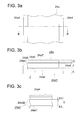
- Fig. 3a through 3c are an enlarged schematic view of the heat-producing fixing belt shown in Fig. 1 .
- Fig. 3a is an enlarged schematic plan view of the heat-producing fixing belt shown in Fig. 1 .
- Fig. 3b is an enlarged schematic cross-sectional view along line B-B' of Fig. 3a.
- Fig. 3c is an enlarged schematic view of the portion shown by Y of Fig. 3b .
- symbol 24a represents a ring-shaped heat-producing fixing belt
- the ring-shaped heat-producing fixing belt 24a is constructed of a heat-producing layer 24a3 having power supplying electrodes 24a1 and 24a2 on its both ends, an elastic layer 24a5 via a primer layer 24a4 except the power supplying electrodes 24a1 and 24a2, and a releasing layer 24a7 via a primer layer 24a6.
- the elastic layer 24a5 and the primer layers 24a4 and 24a6 may be provided as appropriate.
- the surface opposite to the side of the heat-producing layer 24a3 where the elastic layer 24a5 is laminated is brought into contact with the fixing roller 24b (refer to Figs. 2a and 2b ), and the surface opposite to the surface of the releasing layer 24a7 being in contact with the elastic layer 24a5 is brought into contact with the pressure roller 24c (refer to Figs. 2a and 2b ).
- the heat-producing layer 24a3 has fabric 24a31 of carbon fiber and a polyimide resin 24a32 covering the fabric 24a31.
- the resistance between the power supplying electrodes 24a1 and 24a2 of the heat-producing layer 24a3 is preferably 7 ⁇ to 50 ⁇ .
- Symbol 24a31 constituting the heat-producing layer 24a3 is made of carbon fiber and a polyimide resin.
- As the fabric for 24a31 either of textile and knit is employable but from the viewpoint ofless expansion and contraction, textile is preferable.
- the method for forming the power supplying electrodes 24a1 and 24a2 is not specifically limited and for example, a method of bonding of a conductive tape is employable.
- Thickness E represents the thickness of the heat-producing layer. Thickness E is preferably 50 ⁇ m to 600 ⁇ m in view of thermal capacity, and flexibility. Thickness E represents a value in which the cross-section is measured using a reflection-type optical microscope.
- 24a31 containing fabric containing carbon fiber and a polyimide resin is preferably covered with a polyimide resin 23a32.
- Symbols E 1 and E2 represent the thickness of the covered portion of the polyimide resin 24a32 covering 24a31 containing carbon fiber fabric and a polyimide resin. Thicknesses E1 and E2 are preferably 50 ⁇ m to 300 ⁇ m in view of strength. Thicknesses E1 and E2 represent a value in which the cross-section is measured using a reflection-type optical microscope.
- Thickness F represents the thickness of the elastic layer 24a5. Thickness F is preferably 50 ⁇ m to 500 ⁇ m in view of image quality and thermal capacity. Thickness F represents a value in which the cross-section is measured using a reflection-type optical microscope.
- Thickness G represents the thickness of the releasing layer 24a7.
- Thickness G is preferably 1 ⁇ m to 10 ⁇ m, more preferably 1 ⁇ m to 5 ⁇ m, in view of heat transference, flexibility, and durability.
- the thickness is a value measured using an eddy current-type film thickness meter (produced by Fischer Instruments KK).
- Primer layers 24a4 and 24a6 may be provided between the heat-producing layer and the elastic layer or between the elastic layer and the releasing layer as appropriate.
- the thicknesses of the primer layers 24a4 and 24a6 are preferably 2 ⁇ m to 5 ⁇ m.
- the width and diameter of the heat-producing fixing belt 24a can be appropriately determined based on the specifications of an image forming apparatus.
- s 4 is a schematic production flowchart of a heat-producing fixing belt having the configuration shown in Figs. 3a through 3c .
- the heat-producing fixing belt 24a can be produced via a heat-producing layer forming step, an elastic layer forming step, and a releasing layer forming step.
- the heat-producing layer forming step contains a fabric preparing step, a polyimide resin covering step, and a power supplying electrode forming step.
- a loom or knitter is used to prepare annular fabric in which carbon fiber constituting the heat-producing layer is used.
- the annular fabric may be textile or knit which is selectable as needed.
- the annular fabric may be directly produced using a commonly used ring-shaped loom. Alternatively, using a commonly used loom, flat fabric may be produced, followed by bonding to form a ring shape. Annular knit can be produced using a commonly used circular knitter.
- a polyimide resin covering coating liquid (hereinafter, referred to also as a polyimide resin precursor coating liquid) is coated on the periphery of the fabric, followed by heating to form a heat-producing layer in which the fabric is covered with a polyimide resin.
- the polyimide resin covering step will be described in Figs. 5a and 5b .
- a conductive tape is bonded to both ends of the heat-producing layer having been prepared in the polyimide resin covering step to form power supplying electrodes.
- an elastic layer forming coating liquid is coated on the heat-producing layer, except the power supplying electrode portions having been formed in the power supplying electrode forming step, using a coater in the coating step, followed by drying in the drying step to form an elastic layer on the heat-producing layer.
- Coating of the elastic layer forming coating liquid can be carried out in the same manner as for coating of the polyimide resin precursor coating liquid.
- a primer layer may be formed to enhance adhesion properties with respect to the heat-producing layer.
- a releasing layer forming coating liquid is coated on the elastic layer having been formed in the elastic layer forming step using a coater in the coating step, followed by drying in the drying step to remove the core metal, and thereby a heat-producing layer/elastic layer/releasing layer configuration is formed to produce a ring-shaped heat-producing fixing belt.
- Coating of the releasing layer forming coating liquid can be carried out in the same manner as for coating of the polyimide resin precursor coating liquid.
- a primer layer may be formed to enhance adhesion properties with respect to the elastic layer.
- Figs. 5a and 5b are a schematic view of a production apparatus to coat a polyimide resin precursor on the periphery of woven fabric produced using carbon fiber mounted on a columnar core metal to produce woven fabric covered with a polyimide resin.
- Fig. 5a is a schematic perspective view of a production apparatus to coat a polyimide resin precursor on the periphery of woven fabric produced using carbon fiber mounted on a columnar core metal to produce woven fabric covered with a polyimide resin.
- Fig. 5b is a schematic front view of the production apparatus shown in Fig. 5a .
- symbol 9 represents the production apparatus.
- the production apparatus 9 has a holding device 9a, a coating device 9b, and a heating device 9c.
- the holding device 9a has a first holding platform 9a1, a second holding platform 9a2, and a drive motor 9a3.
- the drive motor 9a3 is arranged on the first holding platform 9a1 and connected to the rotational shaft of the drive motor 9a3 via the holding member 9d1 of a columnar core metal 9d and a connection member.
- an accepting section 9a21 to accept the other holding member 9d2 of the columnar core metal 9d is arranged, which thereby makes it possible to carry out holding so that rotation of the drive motor 9a3 rotates and stops the columnar core metal 9d.
- the coating device 9b contains a coating member 9b1 and a drive section 9b2.
- Symbol 9b11 represents a coating liquid feeding pipe to feed a polyimide resin precursor coating liquid to the coating member 9b 1.
- the coating member 9b1 is fixed to a guide rail 9b4 using an fixing member 9b 12 so as to be movable in parallel to the rotational shaft of the columnar core metal 9d.
- the coating member 9b1 includes a nozzle.
- the shape of the ejection opening of a polyimide resin precursor coating liquid of the nozzle is not specifically limited, including for example, a circular shape and a rectangular shape.
- the distance between the ejection opening of a polyimide resin precursor coating liquid of the nozzle and the periphery of the columnar core metal 9d is preferably 1 mm to 100 mm in view of the viscosity of a coating liquid and film thickness.
- a polyimide resin precursor coating liquid feeding section for the coating section 9b I and a control section are omitted.
- the drive section 9b2 contains a motor 9b21 and a guide rail fixing plate 9b3.
- 2 guide rails 9b4 are arranged to fix a fixing member 9b12 and to reciprocate the coating member 9b1 in parallel to the rotational shaft of the columnar core metal 9d held by the holding device 9a.
- the motor 9b21 are screwed with a sliding screw 9b13 fixed on the fixing member 9b12, having an internal screw 9b22 with a length to permit the fixing member 9b 12 to move longer than the width of the columnar core metal 9d held by the holding device 9a.
- Driving the motor 9b21 makes it possible that with rotation of the sliding screw 9b13, the coating member 9b1 fixed to the fixing member 9b 12 reciprocates in parallel to the rotational shaft of the columnar core metal 9d.
- the heating device 9c is arranged below the columnar core metal 9d in order to heat a polyimide resin precursor coated film having been coated on woven fabric mounted on the columnar core metal 9d to give a polyimide resin.
- the heat source of the heating device 9c includes, for example, heating sources such as an IR lamp, nichrome wire, and hot air.
- the present figure shows the case where a columnar core metal was used.
- a cylindrical core metal may be used, being appropriately selectable.
- Woven fabric is mounted on a columnar core metal having been prepared so as to fit into the diameter of carbon fiber woven fabric.
- a polyimide resin precursor coating liquid is ejected from the nozzle onto the periphery ranging from one end to the other end of the woven fabric having been mounted on the core metal 9d and coated on the periphery of the woven fabric to form a coated film.
- Coating can also be carried out in such a manner that the nozzle is reciprocated in the rotational shaft direction in parallel to the rotational shaft of the core metal 9d if appropriate for repetitive coating.
- a polyimide resin precursor coating liquid intended to achieve a needed thickness is coated on the periphery of woven fabric and then heated with rotation of the core metal 9d for imidization to form a heat-producing layer constituting a heat-producing fixing belt covered with a polyimide resin. Subsequently, a conductive tap is bonded to the periphery of both ends of the heat-producing layer to form power supplying electrodes.
- an elastic layer forming coating liquid is coated and dried and subsequently a releasing layer forming coating liquid is coated and dried, followed by removing the core metal to produce a ring-shaped heat-producing fixing belt having a heat-producing layer/elastic layer/surface layer configuration.
- the viscosity of a polyimide resin precursor coating liquid used in the present invention is preferably 3 Pa ⁇ s to 100 Pa ⁇ s from the viewpoint of the permeability to woven fabric, the covering performance with respect to the woven fabric, leveling properties, and handling properties for, e.g., defoaming.
- the viscosity represents a value determined at 25 °C using a digital rotary viscometer (produced by Viscotech Co., Ltd.).
- the boiling point of a solvent used for a polyimide resin precursor coating liquid is preferably 180 °C to 220 °C from the viewpoint of drying rate.
- a heat-producing fixing belt containing a heat-producing layer incorporating a polyimide resin and carbon fiber fabric for the heat-producing layer, an elastic layer, and a releasing layer produces effects as described below. Namely, even with long-term use, resistance value was just slightly varied and then a stable image was able to be obtained. And, even with long-term use, no breakage or crack of the heat-producing layer occurred and then a stable operation was able to be realized.
- the fabric containing carbon fiber With regard to the fabric containing carbon fiber, commercially available carbon fiver fabric is cut into a needed width and then stitched using commercially available carbon fiber to form a ring shape. Further, the fabric containing carbon fiber is obtained by weaving or knitting carbon fiber into a ring shape.
- Carbon fiber and fabric containing carbon fiber are commercially available as trade names of TOREYCA and TOREYCA Cloth (produced by Toray Industries, Inc.) or TENAX (produced by Toho Tenax Co., Ltd.).
- polyimide resin in general, at least one type of aromatic diamine and at least one type of aromatic tetracarboxylic dianhydride are polymerized in an organic polar solvent to from a polyimide precursor, followed by imidization to form a polyimide resin.
- aromatic diamine examples include paraphenylene diamine (PPD), metaphenylene diamine (MPDA), 2,5-diaminotoluene, 2,6-diaminotoluene, 4,4'- diaminobiphenyl, 3,3'-dimethyl-4,4'-biphenyl, 3,3'-dimethoxy-4,4'-biphenyl, 2,2-bis(trifluoromethyl)-4,4'-diaminobiphenyl, 3,3'-diaminodiphenylmethane, 4,4-diaminodiphenylmethane (MDA), 2,2-bis-(4-aminophenyl)propane, 3,3'-diaminodiphenylsulfone (33DDS), 4,4'-diaminodiphenylsulfone (44DDS), 3,3'-diaminodiphenyl sulfide, 4,4'-diaminodiphenyl
- preferable diamines include paraphenylene diamine (PPD), metaphenylene diamine (MPDA), 4,4'-diaminodiphenylmethane (MDA), 3,3'-diaminodiphenylsulfone (33DDS), 4,4'-diaminodiphenylsulfone (44DDS), 3,4'-diaminodiphenyl ether (34ODA), 4,4'-diaminodiphenyl ether (ODA), 1,3-bis(3-aminophenoxy)benzene (133APB), 1,3-bis(4-aminophenoxy)benzene (134APB), bis[4-(3-aminophenoxy)phenyl]sulfone (BAPSM), bis[4-(4-aminophenoxy) phenyl]sulfone (BAPS), and 2,2-bis[4-(4-aminophenoxy) phenyl]propane (BAPP).
- aromatic tetracarboxylic dianhydride examples include pyromellitic dianhydride (PMDA), 1,2,5,6-naphthalene tetracarboxylic dianhydride, 1,4,5,8-naphthalene tetracarboxylic dianhydride, 2,3,6,7-naphthalene tetracarboxylic dianhydride, 2,2',3,3'-biphenyl tetracarboxylic dianhydride, 2,3,3',4'-biphenyl tetracarboxylic dianhydride, 3,3',4,4'-biphenyl tetracarboxylic dianhydride (BPDA), 2,2',3,3'-benzophenone tetracarboxylic dianhydride, 2,3,3',4'-benzophenone tetracarboxylic dianhydride, 3,3',4,4'-benzophenone tetracarboxylic dianhydride,
- preferable tetracarboxylic dianhydrides include pyromellitic dianhydride (PMDA), 3,3',4,4'-biphenyl tetracarboxylic dianhydride (BPDA), 3,3',4,4'-benzophenone tetracarboxylic dianhydride (BTDA), 2,2-bis[3,4-(dicarboxyphenoxy)phenyl]propane dianhydride (BPADA), and oxydiphthalic anhydride (ODPA).
- PMDA pyromellitic dianhydride
- BPDA 3,3',4,4'-biphenyl tetracarboxylic dianhydride
- BTDA 3,3',4,4'-benzophenone tetracarboxylic dianhydride
- BPADA 2,2-bis[3,4-(dicarboxyphenoxy)phenyl]propane dianhydride
- ODPA oxydiphthalic anhydride
- these may be allowed
- aromatic diamines and aromatic tetracarboxylic anhydrides may be used alone or in combination. Further, it is possible that plural types of polyimide precursor solution are prepared to use these polyimide precursor solutions by mixing.
- N,N-dimethylformamide (DMF) and N-methyl-2-pyrrolidone (NMP) are usable.
- the elastic layer is not specifically limited. Any appropriate rubber material and thermoplastic elastomer are usable.
- the material can be selected from those including, for example, styrene-butadiene rubber (SBR), high styrene rubber, polybutadiene rubber (BR), polyisoprene rubber (IIR), ethylene-propylene copolymers, nitrile-butadiene rubber, chloroprene rubber (CR), ethylene-propylene-diene rubber (EPDM), butyl rubber, silicone rubber, fluorite rubber, nitrile rubber, urethane rubber, acrylic rubber (ACM, ANM), epichlorohydrin rubber, and norbornene rubber. These may be used alone or in combination of at least 2 types thereof
- thermoplastic elastomer polyester-based, polyurethane-based, styrene-butadiene triblock-based, or polyolefin-based ones are usable.
- blending agents such as filler, bulking filler, vulcanizing agent, colorant, heat-resistant agents and pigment can be added in the elastic layer depending on the intended use and design of a heat-producing fixing belt.
- the added amounts of blending agents change the degree of plasticity of a synthetic resin. Those having a degree of plasticity of at most 120 are preferably used for synthesized resins prior to curing.
- the releasing layer forming resin is preferably at least one resin selected from the group consisting of polytetrafluoroethylene (PTFE), a tetrafluoroethylene-perfluoroalkyl vinyl ether copolymer (PFA), and a tetrafluoroethylene-hexafluoropropylene copolymer (FEP).
- PTFE polytetrafluoroethylene
- PFA tetrafluoroethylene-perfluoroalkyl vinyl ether copolymer
- FEP tetrafluoroethylene-hexafluoropropylene copolymer
- the size of each carbon fiber represents a value determined based on JIS L0101-1978.
- the yam density of woven fabric represents a value obtained by visually determining the number of yarns in the range of 25 mm x 25 mm.
- the thickness of the woven fabric represents a value obtained by determining its cross-section using a reflection-type optical microscope.
- the coating liquid 20 g of polyamide acid "U-vamish S301" (produced by Ube Industries, Ltd.) was dissolved in 20 ml of a solvent to give a polyimide precursor covering coating liquid.
- the viscosity thereof was determined to be 40 Pa s at 23 °C using a laboratory digital rotary viscometer "VISCOSTAR +H" for high viscosity (produced by Viscotech Co., Ltd.).
- the covering thickness is a value determined by subtracting the thickness of woven fabric from the total thickness.
- the rotational velocity (peripheral velocity) of the core metal represents a value determined using HT-4200 (produced by Ono Sokki Co., Ltd).
- a conductive tape of a width of 25 mm and a thickness of 35 ⁇ m (CU-35C, produced by Sumitomo 3M Ltd.) was once wound on the peripheries of both ends of woven fabric having been covered with a polyimide resin for bonding to form power supplying electrodes.
- the elastic layer forming coating liquid was coated on the heat-producing layer except on the power supplying electrodes in the same manner as for coating of the polyimide resin precursor coating liquid under conditions described below to form an elastic layer forming coated film of a dry film thickness of 200 ⁇ m. Thereafter, with rotation of the core metal at a rotational velocity (peripheral velocity) of 0.1 m/sec, primary vulcanization was carried out at 150 °C for 30 minutes, followed by post vulcanization at 200 °C for 4 hours to form an elastic layer on the heat-producing layer.
- a rotational velocity peripheral velocity
- a PTFE resin and a PFA resin were mixed at a ratio of 7:3 to prepare, as a releasing layer forming coating liquid, a fluorine resin dispersion (trade name: "855-510, "produced by E. I. du Pont de Nemours and Company) in which the solid concentration and the viscosity were prepared to be 45% and 110 mPa ⁇ s.
- a fluorine resin dispersion (trade name: "855-510, "produced by E. I. du Pont de Nemours and Company) in which the solid concentration and the viscosity were prepared to be 45% and 110 mPa ⁇ s.
- the releasing layer forming coating liquid was coated on the elastic layer except on the power supplying electrodes in the same manner as for coating of the elastic layer forming coating liquid under conditions described below to form a releasing layer forming coated film of a dry film thickness of 30 ⁇ m. Thereafter, drying was carried out at room temperature for 30 minutes, and then with rotation of the core metal at a rotational velocity (peripheral velocity) of 0.1 m/sec, heating was carried out at 230 °C for 30 minutes, followed by further heating at 270 °C for 10 minutes to form a releasing layer on the elastic layer.
- a rotational velocity peripheral velocity
- the rotational velocity (peripheral velocity) of the core metal represents a value determined using HT-4200 (produced by Ono Sokki Co., Ltd.).
- the core metal was removed to produce a heat-producing fixing belt having a heat-producing layer/elastic layer/releasing layer configuration as Sample No. 101.
- Heat-fixing belts were produced as Sample Nos. 102 to 107 in the same manner as for Sample No. 101 except that annular woven fabric Nos. 1-2 to 1-7 prepared by changing carbon fiber size, warp density, and woof density as shown in Table 1 were used.
- a stainless steel core metal of a diameter of 30 mm and a width of 400 mm was prepared and mounted on the holding device of the production apparatus shown in Fig. 5 . Then, under conditions described below, the prepared heat-producing layer forming coating liquid was coated on the periphery of the core metal to achieve a dry film thickness of 250 ⁇ m and heated at 150 °C for 3 hours, followed by drying at 320 °C for 120 minutes under nitrogen ambience to give a heat-producing layer.
- the rotational velocity (peripheral velocity) of the core metal represents a value determined using HT-4200 (produced by Ono Sokki Co., Ltd.).
- NASLON produced by Nippon Seisen Co., Ltd.
- the planet type mixer the same planet type mixer as used for Comparative Heat-Producing Fixing Belt 108 was used.
- a stainless steel core metal of a diameter of 30 mm and a width of 400 mm was prepared and mounted on the holding device of the production apparatus shown in Fig. 5 . Then, under conditions described below, the prepared heat-producing layer forming coating liquid was coated on the periphery of the core metal to achieve a dry film thickness of 150 ⁇ m and heated at 150 °C for 3 hours, followed by drying at 320 °C for 120 minutes under nitrogen ambience to give a heat-producing layer.
- the rotational velocity (peripheral velocity) of the core metal represents a value determined using HT-4200 (produced by Ono Sokki Co., Ltd.).
- Produced Sample Nos. 101 to 109 each were mounted on bizhub C360 (produced by Konica Minolta Technologies, Inc.) and a power source of a voltage of 100 V was controlled so that the temperature of the heat-producing belt was raised to 170 °C for power application.
- An image of a pixel ratio of 10% (an original image having a character image of 7%, a portrait photography, a solid white image, and a solid black image divided into quarters) was continuously printed on 500,000 A4-sheets of quality paper (64 g/m 2 ).
- Resistance changing rate % resistance value after 500 , 000 sheet - printing - resistance value prior to printing / resistance value prior to printing ⁇ 100 %
- heat-producing fixing belt sample Nos. 101 to 107 in which the heat-producing layer was constructed of fabric employing carbon fiber covered with a polyimide resin, there was no breakage or crack and also the surface resistance value and volume resistance value changes (resistance changing rates) over long-term use were very favorably expressed.
Landscapes
- Physics & Mathematics (AREA)
- General Physics & Mathematics (AREA)
- Fixing For Electrophotography (AREA)
- Laminated Bodies (AREA)
- Surface Heating Bodies (AREA)
- Resistance Heating (AREA)
- Electrostatic Charge, Transfer And Separation In Electrography (AREA)
Abstract
Description
- This application is based on Japanese Patent Application No.
2011-178780 filed on August 18, 2011 - The present invention relates to a heat-producing fixing belt to thermally fix a dry toner image formed by an electrostatic latent image developing system such as electrophotography and an image forming apparatus using the same.
- Conventionally, in image forming apparatuses such as copiers and laser beam printers, a method, in which after toner development, an unfixed toner image having been transferred on an image support such as plain paper is subjected to contact heating fixing using a heat roller system, has been used in many cases.
- However, in such a heat roller system, it takes long time to achieve the fixable temperature by heating and also a large amount of heating energy is required. From the viewpoint of shortening the time from power activation to copy start (the warming-up time) and of energy saving, recently, a heat film fixing system has become mainstream.
- In a fixing device (fixing unit) of this heat film fixing system, a seamless fixing belt, in which a releasable layer of e.g., a fluorine resin is laminated on the outer surface of a heat-resistant film of e.g., polyimide, is used.
- However, in a fixing device of such a heat film fixing system, since a film is heated, for example, via a ceramic heater and then a toner image is fixed on the film surface, the thermal conductivity of the film becomes critical. However, when the fixing belt film is allowed to be thinner to improve the thermal conductivity, mechanical strength tends to decrease and then it becomes difficult to realize high-speed rotation, whereby formation of a high quality image at high speed becomes problematic and also a problem such that the ceramic heater is liable to break is produced.
- To solve such problems, recently, a fixing belt itself provided with a heat-producing body (hereinafter, referred to as a heat-producing fixing belt) has been investigated and then a method has been proposed in which power is supplied to this heat-producing body, whereby the fixing belt is directly heated to fix a toner image. In an image forming apparatus using such a heat-producing fixing belt, warming-up time is shortened and power consumption is further reduced compared to the heat film fixing system. Therefore, a heat fixing device has been investigated, since excellent energy saving and speeding up are exhibited.
- There is known a fixing belt having a heat-producing belt of a three-dimensional network structural body in which a core material made of, for example, iron, SUS, copper, cobalt, nickel, chromium, aluminum, gold, platinum, silver, tin, or palladium is covered with a fluorine resin, polyimide resin, polyamide resin, or polyamideimide resin (refer to, for example, Patent Document 1).
- A heat-producing fixing belt provided with a heat-producing layer incorporating a polyimide resin in which a carbon nanomaterial and filament metal fine particles are dispersed, an insulating layer, and a releasing layer is known (refer to, for example, Patent Document 2).
- There is known a heat-producing fixing belt having an insulating layer incorporating a polyimide resin, a resistance heat-producing body layer in which in a matrix resin containing a polyimide resin, a carbon nanomaterial and filament metal fine particles are substantially uniformly present by dispersion and, a releasing layer, and an electrode layer (refer to, for example, Patent Document 3).
-
- Patent Document 1: Unexamined Japanese Patent Application Publication No.
2006-343538 - Patent Document 2: Unexamined Japanese Patent Application Publication No.
2007-272223 - Patent Document 3: Unexamined Japanese Patent Application Publication No.
2009-109997 - However, the heat-producing fixing belt described in
Patent Document 1 becomes oxidized over long-tem use, resulting in an increase in resistance. Thereby, it was found that the problem that a predetermined heat-producing amount was not obtained was produced. - In the heat-producing fixing belt described in
Patent Document 2, with heating and cooling of a polyimide resin, the resin is elasticized, resulting in a change in resistance. It was found that at the interface between the filler and the resin, cracks and breakages occurred and then such a portion had a problem such that fixing could not be sufficiently carried out - In the heat-producing fixing belt described in
Patent Document 3, with heating and cooling of a polyimide resin, the resin is elasticized, resulting in a change in resistance. It was found that at the interface between the filler and the resin, cracks and breakages occurred and then such a portion had a problem such that fixing could not be sufficiently carried out. - In view of such situations, it has been expected to develop a heat-producing fixing belt in which even with long-term use, surface resistance value and volume resistance value are varied just to a small extent and the heat-producing layer is prevented from breaking and cracking; and an image forming apparatus using this heat-producing fixing belt.
- In view of the above situations, the present invention was completed and an object thereof is to provide a heat-producing fixing belt in which even with long-term use, surface resistance value and volume resistance value are varied just to a smell extent and the heat-producing layer is prevented from cracking and breaking; and an image forming apparatus using this heat producing fixing belt
- The above object of the present invention is achieved by the following technical aspects.
- 1. A heat-producing fixing belt of a cylindrical shape containing a heat-producing layer, an elastic layer, and a releasing layer in this sequential order from the inner side, in which
the heat-producing layer contains a polyimide resin and fabric containing carbon fiber and
a pair of electrodes to supply power to the heat-producing layer making contact with the fabric containing carbon fiber are provided on both ends of the cylindrical shape. - 2. The heat-producing fixing belt described in
aspect 1, in which the size of the carbon fiber is 66 tex to 800 tex. - 3. The heat-producing fixing belt described in
aspect - 4. An image forming apparatus using the heat-producing fixing belt described in any of
aspects 1 to 3. - The present inventors investigated why cracks and breakages occurred over time due to long-term use while the variation of the surface resistance value and the variation of the volume resistance value were small, and then found the following.
- When a belt used over a long term in which fixing nonuniformity occurred was analyzed, cracks and breakages of the heat-producing layer were observed. It was assumed that in the cracked and broken portions, no current flowed and then no heat was produced, resulting in fixing nonuniformity. In other words, it can be said that the presence of discontinuous filler induces such cracks and breakages.
- Hence, to realize the state where oxidation resistance is enhanced and continued in order to allow this discontinuous filler to be continuous, heat-producing elements were investigated. Thereby, it was found out that when fabric employing carbon fiber was used as the heat-producing element, this problem was able to be solved.
- There were able to be provided a heat-producing fixing belt in which surface resistance value and volume resistance value were varied just to a small extent and the heat-producing layer was prevented from cracking and breaking; and an image forming apparatus using this heat-producing fixing belt.
-
-
Fig. 1 is a schematic cross-sectional configuration view showing one example of an electrophotogaphic image forming apparatus; -
Figs. 2a and 2b are an enlarged schematic view of a fixing device used in the image forming apparatus shown inFig. 1 ; -
Figs. 3a through 3c are an enlarged schematic view of the heat-producing fixing belt shown inFig. 1 ; -
Fig. 4 is a schematic production flowchart of a heat-producing fixing belt having the configuration shown inFigs. 3a through 3c ; and -
Figs. 5a and 5b are a schematic view of a production apparatus to coat a polyimide resin precursor on the periphery of fabric produced using carbon fiber mounted on a columnar core metal to produce fabric coated with a polyimide resin. - An embodiment of the present invention will now be described with reference to Figures but the present invention is not limited thereto.
-
Fig. 1 is a schematic cross-sectional configuration view showing one example of an electrophotographic image forming apparatus. This figure shows the case of a full-color image forming apparatus. - In the figure,
symbol 1 shows a full-color image forming apparatus. The full-colorimage forming apparatus 1 has a plural set ofimage forming units body forming unit 7 as the transfer section; an endless belt-shaped sheetfeeding conveyance member 21 to convey a recording medium P, and abelt fixing device 24 as the fixing member. On top of the main body A of the full-colorimage forming apparatus 1, a document image reading apparatus SC is arranged. - The
image forming unit 10Y to form an image of yellow as one of the different color toner images formed each onphotoreceptors drum photoreceptor 1Y as a first image carrier, acharging member 2Y arranged in the periphery of thephotoreceptor 1Y, anexposure member 3 Y, a developingmember 4Y having a developer carrier 4Y1, aprimary transfer roller 5Y as the primary transfer member, and acleaning member 6Y. - Further, the
image forming unit 10M to form an image of magenta as another different color toner image has adrum photoreceptor 1M as a first image carrier, a chargingmember 2M arranged in the periphery of thephotoreceptor 1M, anexposure member 3M, a developingmember 4M having a developer carrier 4M1, aprimary transfer roller 5M as the primary transfer member, and a cleaningmember 6M. - Further, the
image forming unit 10C to form an image of cyan as another different color toner image has adrum photoreceptor 1 C as a first image carrier, a chargingmember 2C arranged in the periphery of thephotoreceptor 1C, anexposure member 3C, a developingmember 4C having a developer carrier 4C1, aprimary transfer roller 5C as the primary transfer member, and a cleaningmember 6C. - Further, the
image forming unit 10K to form an image of black as another different color toner image has a drum photoreceptor I K as a first image carrier, a chargingmember 2K arranged in the periphery of thephotoreceptors 1K, anexposure member 3K, a developingmember 4K having a developer carrier 4K1, aprimary transfer roller 5K as the primary transfer member, and a cleaningmember 6K. - The endless belt-shaped intermediate transfer
body forming unit 7 has an endlessintermediate transfer belt 70 as a second image carrier of a semiconductive endless belt shape wound around a plurality of rollers and rotatably supported. - Each color image having been formed by the
image forming untis intermediate transfer belt 70 using theprimary transfer rollers sheet feeding cassette 20 is fed by asheet feeding member 21 and then conveyed to asecondary transfer roller 5A as the secondary transfer member via a plurality ofintermediate rollers registration roller 23 to collectively transfer a color image onto the recording medium P. - The recording medium P on which the color image has been transferred is subjected to fixing using the fixing
device 24 in which a ring-shaped heat-producingfixing belt 24a and then nipped by asheet discharging roller 25 to be stacked on asheet discharging tray 26 outside the apparatus. - On the other hand, the color image is transferred onto the recording medium P using the
secondary transfer roller 5A and thereafter, from the endlessintermediate transfer belt 70 having curvature-separated the recording medium P, the residual toner is eliminated by the cleaningmember 6A. - During image formation, the
primary transfer roller 5K is always in pressure contact with thephotoreceptor 1K. The otherprimary rollers photoreceptors - The
secondary transfer roller 5A is brought into pressure contact with the endlessintermediate transfer belt 70 only when a recording medium P is passed through this roller for secondary transfer. - Further, a
housing 8 is allowed to be withdrawable from the apparatus main body A viasupport rails housing 8 has theimage forming units body forming unit 7. - The
image forming units photoreceptors body forming unit 7 is arranged. The endless belt-shaped intermediate transferbody forming unit 7 has the endlessintermediate transfer belt 70 wound aroundrollers primary transfer rollers member 6A. - Via the withdrawing operation of the
housing 8, theimage forming units body forming unit 7 are integrally withdrawn from the main body A. - In this manner, each outer periphery of the
photoreceptors intermediate transfer belt 70, collectively transferred onto a recording medium P, and secured and fixed by pressurization and heating using thebelt fixing device 24. "During image formation" referred to in the present invention includes latent image formation and final image formation via transfer of a toner image (a visualized image) onto a recording medium P. - In the
photoreceptors cleaning members photoreceptors - In the color image forming apparatus, as the cleaning member for the cleaning
member 6A to clean the intermediate transfer body, an elastic blade is used. Further, a member (11Y, 11M, 11C, and 11K, each) to coat a fatty acid metallic salt on each photoreceptor is provided. As the fatty acid metallic salt, the same salt as used in the toner is employable. - The present invention relates to a ring-shaped heat-producing
fixing belt 24a used in the fixingdevice 24 shown in the present figure. -
Fig. 2a and 2b are an enlarged schematic view of a fixing device used in the image forming apparatus shown inFig. 1 .Fig. 2a is an enlarged schematic perspective view of the fixing device used in the image forming apparatus shown inFig. 1 .Fig. 2b is a schematic cross-sectional view along line A-A' shown inFig. 2a . - In the figure,
symbol 24 represents a fixing device. The fixingdevice 24 has a ring-shaped heat-producingfixing belt 24a, a fixingroller 24b, and apressure roller 24c rotating with bringing the ring-shaped heat-producingfixing belt 24a into pressure contact therewith. - The fixing
roller 24 is a drive roller, and with rotation of the fixingroller 24b (in the arrow direction in the figure), the ring-shaped heat-producingfixing belt 24a is allowed to be wound around in the arrow direction. - Via the ring-shaped heat-producing
fixing belt 24a, a fixing nip portion N is formed between the fixingroller 24b and thepressure roller 24c. The fixing nip portion N nips a recording medium P on which a toner image (a visualized image) has been transferred (refer toFig. 1 ) and then the toner image (the visualized image) is melted and fixed by the ring-shaped heat-producingfixing belt 24a to form a final image. - The side making contact with the fixing
roller 24b of the ring-shaped heat-producingfixing belt 24a is the heat-producing layer 24a3 (refer toFigs. 3b and 3c ) and the side making contact with thepressure roller 24c is the releasing layer 24a7 (refer toFig. 3b ). - Symbol 24a1 represents a power supplying electrode provided at one edge of the heat-producing
fixing belt 24a, and symbol 24a2 represents a power supplying electrode provided at the other edge of the heat-producingfixing belt 24a. The power supplying electrode 24a1 and the power supplying electrode 24a1 are paired. - Symbol 24d1 makes contact with the power supplying electrode 24a1 and represents a power supplying member to supply power to the heat-producing
fixing belt 24a. Symbol 24d2 makes contact with the power supplying electrode 24a2 and represents a power supplying member to supply power to the heat-producingfixing belt 24a. In view of the temperature and the fixing stability of the ring-shaped heat-producingfixing belt 24a, in order to stabilize the contact between the power supplying electrode 24a1 and the power supplying member 24d1, the position where the power supplying member is arranged is preferably the position where the power supplying electrode 24a1 makes contact with the fixingroller 24b and at the same time, being in the vicinity of the fixing nip portion N. - To make uniform contact with the power supplying electrodes, the power supplying member is preferably brought into contact with the power supplying electrodes by pressing using a pressing member (e.g., a spring).
-
Fig. 3a through 3c are an enlarged schematic view of the heat-producing fixing belt shown inFig. 1 .Fig. 3a is an enlarged schematic plan view of the heat-producing fixing belt shown inFig. 1 .Fig. 3b is an enlarged schematic cross-sectional view along line B-B' ofFig. 3a. Fig. 3c is an enlarged schematic view of the portion shown by Y ofFig. 3b . - In the figure,
symbol 24a represents a ring-shaped heat-producing fixing belt The ring-shaped heat-producingfixing belt 24a is constructed of a heat-producing layer 24a3 having power supplying electrodes 24a1 and 24a2 on its both ends, an elastic layer 24a5 via a primer layer 24a4 except the power supplying electrodes 24a1 and 24a2, and a releasing layer 24a7 via a primer layer 24a6. The elastic layer 24a5 and the primer layers 24a4 and 24a6 may be provided as appropriate. - In the present figure, the surface opposite to the side of the heat-producing layer 24a3 where the elastic layer 24a5 is laminated is brought into contact with the fixing
roller 24b (refer toFigs. 2a and 2b ), and the surface opposite to the surface of the releasing layer 24a7 being in contact with the elastic layer 24a5 is brought into contact with thepressure roller 24c (refer toFigs. 2a and 2b ). - The heat-producing layer 24a3 has fabric 24a31 of carbon fiber and a polyimide resin 24a32 covering the fabric 24a31.
- The resistance between the power supplying electrodes 24a1 and 24a2 of the heat-producing layer 24a3 is preferably 7 Ω to 50 Ω.
- Symbol 24a31 constituting the heat-producing layer 24a3 is made of carbon fiber and a polyimide resin. As the fabric for 24a31, either of textile and knit is employable but from the viewpoint ofless expansion and contraction, textile is preferable.
- The method for forming the power supplying electrodes 24a1 and 24a2 is not specifically limited and for example, a method of bonding of a conductive tape is employable.
- Symbol E represents the thickness of the heat-producing layer. Thickness E is preferably 50 µm to 600 µm in view of thermal capacity, and flexibility. Thickness E represents a value in which the cross-section is measured using a reflection-type optical microscope. In the heat-producing layer, as shown in
Fig. 3c , 24a31 containing fabric containing carbon fiber and a polyimide resin is preferably covered with a polyimide resin 23a32. -
Symbols E 1 and E2 represent the thickness of the covered portion of the polyimide resin 24a32 covering 24a31 containing carbon fiber fabric and a polyimide resin. Thicknesses E1 and E2 are preferably 50 µm to 300 µm in view of strength. Thicknesses E1 and E2 represent a value in which the cross-section is measured using a reflection-type optical microscope. - Symbol F represents the thickness of the elastic layer 24a5. Thickness F is preferably 50 µm to 500 µm in view of image quality and thermal capacity. Thickness F represents a value in which the cross-section is measured using a reflection-type optical microscope.
- Symbol G represents the thickness of the releasing layer 24a7. Thickness G is preferably 1 µm to 10 µm, more preferably 1 µm to 5 µm, in view of heat transference, flexibility, and durability. The thickness is a value measured using an eddy current-type film thickness meter (produced by Fischer Instruments KK).
- Primer layers 24a4 and 24a6 may be provided between the heat-producing layer and the elastic layer or between the elastic layer and the releasing layer as appropriate. The thicknesses of the primer layers 24a4 and 24a6 are preferably 2 µm to 5 µm.
- The width and diameter of the heat-producing
fixing belt 24a can be appropriately determined based on the specifications of an image forming apparatus. - Next, the method for producing the heat-producing fixing belt shown in
FIGS. 1 to 3 will be described. - s 4 is a schematic production flowchart of a heat-producing fixing belt having the configuration shown in
Figs. 3a through 3c . - The heat-producing
fixing belt 24a can be produced via a heat-producing layer forming step, an elastic layer forming step, and a releasing layer forming step. - The heat-producing layer forming step contains a fabric preparing step, a polyimide resin covering step, and a power supplying electrode forming step.
- In the fabric preparing step, a loom or knitter is used to prepare annular fabric in which carbon fiber constituting the heat-producing layer is used. The annular fabric may be textile or knit which is selectable as needed.
- The annular fabric may be directly produced using a commonly used ring-shaped loom. Alternatively, using a commonly used loom, flat fabric may be produced, followed by bonding to form a ring shape. Annular knit can be produced using a commonly used circular knitter.
- In the polyimide resin covering step, in the state where the fabric having been prepared in the fabric preparing step is mounted on a core metal allowed to fit into the diameter of the annular fabric, using a coater, a polyimide resin covering coating liquid (hereinafter, referred to also as a polyimide resin precursor coating liquid) is coated on the periphery of the fabric, followed by heating to form a heat-producing layer in which the fabric is covered with a polyimide resin. The polyimide resin covering step will be described in
Figs. 5a and 5b . - In the power supplying electrode forming step, using a tape bonding machine, a conductive tape is bonded to both ends of the heat-producing layer having been prepared in the polyimide resin covering step to form power supplying electrodes.
- In the elastic layer forming step containing a coating step and a drying step, an elastic layer forming coating liquid is coated on the heat-producing layer, except the power supplying electrode portions having been formed in the power supplying electrode forming step, using a coater in the coating step, followed by drying in the drying step to form an elastic layer on the heat-producing layer. Coating of the elastic layer forming coating liquid can be carried out in the same manner as for coating of the polyimide resin precursor coating liquid. Prior to coating of the elastic layer forming coating liquid, a primer layer may be formed to enhance adhesion properties with respect to the heat-producing layer.
- In the releasing layer forming step containing a coating step and a drying step, a releasing layer forming coating liquid is coated on the elastic layer having been formed in the elastic layer forming step using a coater in the coating step, followed by drying in the drying step to remove the core metal, and thereby a heat-producing layer/elastic layer/releasing layer configuration is formed to produce a ring-shaped heat-producing fixing belt. Coating of the releasing layer forming coating liquid can be carried out in the same manner as for coating of the polyimide resin precursor coating liquid. Prior to coating of the releasing layer forming coating liquid, a primer layer may be formed to enhance adhesion properties with respect to the elastic layer.
-
Figs. 5a and 5b are a schematic view of a production apparatus to coat a polyimide resin precursor on the periphery of woven fabric produced using carbon fiber mounted on a columnar core metal to produce woven fabric covered with a polyimide resin.Fig. 5a is a schematic perspective view of a production apparatus to coat a polyimide resin precursor on the periphery of woven fabric produced using carbon fiber mounted on a columnar core metal to produce woven fabric covered with a polyimide resin.Fig. 5b is a schematic front view of the production apparatus shown inFig. 5a . - In the figure,
symbol 9 represents the production apparatus. Theproduction apparatus 9 has aholding device 9a, acoating device 9b, and aheating device 9c. The holdingdevice 9a has a first holding platform 9a1, a second holding platform 9a2, and a drive motor 9a3. The drive motor 9a3 is arranged on the first holding platform 9a1 and connected to the rotational shaft of the drive motor 9a3 via the holding member 9d1 of acolumnar core metal 9d and a connection member. In the second holding platform 9a2, an accepting section 9a21 to accept the other holding member 9d2 of thecolumnar core metal 9d is arranged, which thereby makes it possible to carry out holding so that rotation of the drive motor 9a3 rotates and stops thecolumnar core metal 9d. - The
coating device 9b contains a coating member 9b1 and a drive section 9b2. Symbol 9b11 represents a coating liquid feeding pipe to feed a polyimide resin precursor coating liquid to thecoating member 9bmember 9b 12 so as to be movable in parallel to the rotational shaft of thecolumnar core metal 9d. The coating member 9b1 includes a nozzle. The shape of the ejection opening of a polyimide resin precursor coating liquid of the nozzle is not specifically limited, including for example, a circular shape and a rectangular shape. The distance between the ejection opening of a polyimide resin precursor coating liquid of the nozzle and the periphery of thecolumnar core metal 9d is preferably 1 mm to 100 mm in view of the viscosity of a coating liquid and film thickness. In the present figure, a polyimide resin precursor coating liquid feeding section for thecoating section 9b I and a control section are omitted. - The drive section 9b2 contains a motor 9b21 and a guide rail fixing plate 9b3. In the guide rail fixing plate 9b3, 2 guide rails 9b4 are arranged to fix a fixing member 9b12 and to reciprocate the coating member 9b1 in parallel to the rotational shaft of the
columnar core metal 9d held by the holdingdevice 9a. - The motor 9b21 are screwed with a sliding screw 9b13 fixed on the fixing member 9b12, having an internal screw 9b22 with a length to permit the fixing
member 9b 12 to move longer than the width of thecolumnar core metal 9d held by the holdingdevice 9a. - Driving the motor 9b21 makes it possible that with rotation of the sliding screw 9b13, the coating member 9b1 fixed to the fixing
member 9b 12 reciprocates in parallel to the rotational shaft of thecolumnar core metal 9d. - The
heating device 9c is arranged below thecolumnar core metal 9d in order to heat a polyimide resin precursor coated film having been coated on woven fabric mounted on thecolumnar core metal 9d to give a polyimide resin. The heat source of theheating device 9c includes, for example, heating sources such as an IR lamp, nichrome wire, and hot air. - In the production apparatus shown in the present figure, there was shown the case where imidization of a polyimide resin precursor coated film having been coated on woven fabric mounted on a cylindrical core metal was incorporated in one production apparatus. However, a method in which the
holding device 9a is allowed to movable and heating treatment is carried out in another step is employable. Further, a method of heating a cylindrical core metal from the interior is employable. - The present figure shows the case where a columnar core metal was used. However, a cylindrical core metal may be used, being appropriately selectable.
- There will be briefly described steps in which using the
production apparatus 9 shown in the present figure, woven fabric mounted on a core metal is coated with a polyimide resin to produce a heat-producing layer 24a3 (refer toFigs. 3a and 3b ) constituting a ring-shaped heat-producingfixing belt 24a (refer toFigs. 2a and 2b ). - Woven fabric is mounted on a columnar core metal having been prepared so as to fit into the diameter of carbon fiber woven fabric.
- In the state where the
core metal 9d on which the woven fabric has been mounted is held by the holdingdevice 9a and thecore metal 9d is rotated, as a nozzle serving as the coating member 9b1 is moved in the rotational shaft direction in parallel to the rotational shaft of thecore metal 9d, a polyimide resin precursor coating liquid is ejected from the nozzle onto the periphery ranging from one end to the other end of the woven fabric having been mounted on thecore metal 9d and coated on the periphery of the woven fabric to form a coated film. - Coating can also be carried out in such a manner that the nozzle is reciprocated in the rotational shaft direction in parallel to the rotational shaft of the
core metal 9d if appropriate for repetitive coating. - A polyimide resin precursor coating liquid intended to achieve a needed thickness is coated on the periphery of woven fabric and then heated with rotation of the
core metal 9d for imidization to form a heat-producing layer constituting a heat-producing fixing belt covered with a polyimide resin. Subsequently, a conductive tap is bonded to the periphery of both ends of the heat-producing layer to form power supplying electrodes. - Then, using the
production apparatus 9, in the same manner as for coating of the polyimide resin precursor coating liquid, an elastic layer forming coating liquid is coated and dried and subsequently a releasing layer forming coating liquid is coated and dried, followed by removing the core metal to produce a ring-shaped heat-producing fixing belt having a heat-producing layer/elastic layer/surface layer configuration. - The viscosity of a polyimide resin precursor coating liquid used in the present invention is preferably 3 Pa·s to 100 Pa·s from the viewpoint of the permeability to woven fabric, the covering performance with respect to the woven fabric, leveling properties, and handling properties for, e.g., defoaming.
- The viscosity represents a value determined at 25 °C using a digital rotary viscometer (produced by Viscotech Co., Ltd.).
- The boiling point of a solvent used for a polyimide resin precursor coating liquid is preferably 180 °C to 220 °C from the viewpoint of drying rate.
- A heat-producing fixing belt containing a heat-producing layer incorporating a polyimide resin and carbon fiber fabric for the heat-producing layer, an elastic layer, and a releasing layer produces effects as described below. Namely, even with long-term use, resistance value was just slightly varied and then a stable image was able to be obtained. And, even with long-term use, no breakage or crack of the heat-producing layer occurred and then a stable operation was able to be realized.
- Materials used for each layer constituting the heat-producing fixing belt of the present invention will now be described.
- With regard to the fabric containing carbon fiber, commercially available carbon fiver fabric is cut into a needed width and then stitched using commercially available carbon fiber to form a ring shape. Further, the fabric containing carbon fiber is obtained by weaving or knitting carbon fiber into a ring shape. Carbon fiber and fabric containing carbon fiber are commercially available as trade names of TOREYCA and TOREYCA Cloth (produced by Toray Industries, Inc.) or TENAX (produced by Toho Tenax Co., Ltd.).
- With regard to the polyimide resin, in general, at least one type of aromatic diamine and at least one type of aromatic tetracarboxylic dianhydride are polymerized in an organic polar solvent to from a polyimide precursor, followed by imidization to form a polyimide resin.
- Typical examples of the aromatic diamine include paraphenylene diamine (PPD), metaphenylene diamine (MPDA), 2,5-diaminotoluene, 2,6-diaminotoluene, 4,4'- diaminobiphenyl, 3,3'-dimethyl-4,4'-biphenyl, 3,3'-dimethoxy-4,4'-biphenyl, 2,2-bis(trifluoromethyl)-4,4'-diaminobiphenyl, 3,3'-diaminodiphenylmethane, 4,4-diaminodiphenylmethane (MDA), 2,2-bis-(4-aminophenyl)propane, 3,3'-diaminodiphenylsulfone (33DDS), 4,4'-diaminodiphenylsulfone (44DDS), 3,3'-diaminodiphenyl sulfide, 4,4'-diaminodiphenyl sulfide, 3,3'-diaminodiphenyl ether, 3,4'-diaminodiphenyl ether (34ODA), 4,4'-diaminodiphenyl ether (ODA), 1,5-diaminonaphthalene, 4,4'-diaminodiphenyl diethylsilane, 4,4'-diaminodiphenyl silane, 4,4'-diaminodiphenylethyl phosphine oxide, 1,3-bis(3-aminophenoxy)benzene (133APB), 1,3-bis(4-aminophenoxy)benzene (134APB), 1,4-bis(4-aminophenaxy)benzene, bis[4-(3-aminophenoxy) phenyl]sulfone (BAPSM), bis[4-(4-aminophenoxy)phenyl]sulfone (BAPS), 2,2-bis[4-(4-aminophenoxy) phenyl]propane (BAPP), 2,2-bis(3-aminophenyl)1,1,1,3,3,3-hexafluoropropane, 2,2-bis(4-aminophenyl)1,1,1,3,3,3-hexafluoropropane, and 9,9-bis(4-aminophenyl)fluorene. Of these, preferable diamines include paraphenylene diamine (PPD), metaphenylene diamine (MPDA), 4,4'-diaminodiphenylmethane (MDA), 3,3'-diaminodiphenylsulfone (33DDS), 4,4'-diaminodiphenylsulfone (44DDS), 3,4'-diaminodiphenyl ether (34ODA), 4,4'-diaminodiphenyl ether (ODA), 1,3-bis(3-aminophenoxy)benzene (133APB), 1,3-bis(4-aminophenoxy)benzene (134APB), bis[4-(3-aminophenoxy)phenyl]sulfone (BAPSM), bis[4-(4-aminophenoxy) phenyl]sulfone (BAPS), and 2,2-bis[4-(4-aminophenoxy) phenyl]propane (BAPP).
- Further, typical examples of the aromatic tetracarboxylic dianhydride include pyromellitic dianhydride (PMDA), 1,2,5,6-naphthalene tetracarboxylic dianhydride, 1,4,5,8-naphthalene tetracarboxylic dianhydride, 2,3,6,7-naphthalene tetracarboxylic dianhydride, 2,2',3,3'-biphenyl tetracarboxylic dianhydride, 2,3,3',4'-biphenyl tetracarboxylic dianhydride, 3,3',4,4'-biphenyl tetracarboxylic dianhydride (BPDA), 2,2',3,3'-benzophenone tetracarboxylic dianhydride, 2,3,3',4'-benzophenone tetracarboxylic dianhydride, 3,3',4,4'-benzophenone tetracarboxylic dianhydride (BTDA), bis(3,4-dicarboxyphenyl)sulfone dianhydride, bis(2,3-dicarboxyphenyl)methane dianhydride bis(3,4-dicarboxyphenyl)methane dianhydnde, 1,1-bis(2,3-dicarboxyphenyl)ethane dianhydride, 1,1-bis(3,4-dicarboxyphenyl)ethane dianhydride, 2,2-bis[3,4-(dicarboxyphenoxy)phenyl]propane dianhydride (BPADA), 4,4'-(hexafluoroisopropylidene)diphthalic anhydride, oxydiphthalic anhydride (ODPA), bis(3,4-dicarboxyphenyl)sulfone dianhydride, bis(3,4-dicarboxyphenyl)sulfoxide dianhydride, thiodiphthalic dianhydride, 3,4,9,10-perylenetetracarboxylic dianhydride, 2,3,6,7-anthracenetetracarboxylic dianhydride, 1,2,7,8-phenanthrenetetracarboxylic dianhydride, 3,9-bis{3,4-dicarboxyphenyl)fluorine dianhydride, and 9,9-bis[4-(3,4'-dicarboxyphenoxy)pbenyl]fluorene dianhydride. Of these, preferable tetracarboxylic dianhydrides include pyromellitic dianhydride (PMDA), 3,3',4,4'-biphenyl tetracarboxylic dianhydride (BPDA), 3,3',4,4'-benzophenone tetracarboxylic dianhydride (BTDA), 2,2-bis[3,4-(dicarboxyphenoxy)phenyl]propane dianhydride (BPADA), and oxydiphthalic anhydride (ODPA). Incidentally, these may be allowed to react with alcohol such as methanol or ethanol to form ester compounds.
- These aromatic diamines and aromatic tetracarboxylic anhydrides may be used alone or in combination. Further, it is possible that plural types of polyimide precursor solution are prepared to use these polyimide precursor solutions by mixing.
- N,N-dimethylformamide (DMF) and N-methyl-2-pyrrolidone (NMP) are usable.
- The elastic layer is not specifically limited. Any appropriate rubber material and thermoplastic elastomer are usable. The material can be selected from those including, for example, styrene-butadiene rubber (SBR), high styrene rubber, polybutadiene rubber (BR), polyisoprene rubber (IIR), ethylene-propylene copolymers, nitrile-butadiene rubber, chloroprene rubber (CR), ethylene-propylene-diene rubber (EPDM), butyl rubber, silicone rubber, fluorite rubber, nitrile rubber, urethane rubber, acrylic rubber (ACM, ANM), epichlorohydrin rubber, and norbornene rubber. These may be used alone or in combination of at least 2 types thereof
- On the other hand, as the thermoplastic elastomer, polyester-based, polyurethane-based, styrene-butadiene triblock-based, or polyolefin-based ones are usable.
- Further, blending agents such as filler, bulking filler, vulcanizing agent, colorant, heat-resistant agents and pigment can be added in the elastic layer depending on the intended use and design of a heat-producing fixing belt. The added amounts of blending agents change the degree of plasticity of a synthetic resin. Those having a degree of plasticity of at most 120 are preferably used for synthesized resins prior to curing.
- The releasing layer forming resin is preferably at least one resin selected from the group consisting of polytetrafluoroethylene (PTFE), a tetrafluoroethylene-perfluoroalkyl vinyl ether copolymer (PFA), and a tetrafluoroethylene-hexafluoropropylene copolymer (FEP).
- The present invention will now specifically be described with reference to examples.
- Via the following method, heat-producing fixing belts configured as shown in
Figs. 3a through 3c were produced to prepare Sample Nos. 101 to 109. - Woven fabrics (produced by Toray Industries, Inc.) using the carbon fibers shown in Table 1 were stitched using carbon fiber to obtain annular woven fabrics.
Table 1 Fabric containing carbon fiber No. Material Carbon Fiber Size (tex) Warp Density (yarns/25 mm) Woof Density (yarns/25 mm) Thickness (µm) 1-1 TOREYCA Cloth C06343 (produced by Toray Industries, Inc.) 198 12.5 12.5 230 1-2 TOREYCA Cloth C061432 (produced by Toray Industries, Inc.) 66 22.5 22.5 150 1-3 Carbon Fiber UTS-50 (produced by Tobo Tenax Co., Ltd.) 800 7.5 7.5 600 1-4 Carbon Fiber HTA-40 (produced by Toho Tenax Co., Ltd.) 60 12.5 12.5 220 1-5 Carbon Fiber IMS-50 (produced by Toho Tenax Co., Ltd.) 850 7.5 7.5 600 1-6 Carbon Fiber HTS-40 (produced by Toho Tenax Co., Ltd.) 800 6.0 6.0 260 1-7 TOREYCA Fiber T-300 (produced by Toray Industries, Inc.) 66 25.0 25.0 170 - 1-1 and 1-2 were produced by annularly stitching fabric. With respect to 1-3 to 1-7, carbon fiber was woven to produce a cylindrical fabric. Thickness in Table 1 represents the thickness corresponding to symbol 24a31 in
Fig. 3C . - The size of each carbon fiber represents a value determined based on JIS L0101-1978.
- The yam density of woven fabric represents a value obtained by visually determining the number of yarns in the range of 25 mm x 25 mm. The thickness of the woven fabric represents a value obtained by determining its cross-section using a reflection-type optical microscope.
- With regard to the coating liquid, 20 g of polyamide acid "U-vamish S301" (produced by Ube Industries, Ltd.) was dissolved in 20 ml of a solvent to give a polyimide precursor covering coating liquid.
- The viscosity thereof was determined to be 40 Pa s at 23 °C using a laboratory digital rotary viscometer "VISCOSTAR +H" for high viscosity (produced by Viscotech Co., Ltd.).
- Prepared annular woven fabric No. 1-1 was mounted on a stainless steel core metal and then using the production apparatus shown in
Fig. 5 , a prepared Polyimide precursor covering coating liquid was coated at a covering thickness (thickness corresponding to the sum of E1 and E2 inFig. 3C ) of 300 µm under conditions described below. Then, with rotation at a rotational velocity (peripheral velocity) of 0.1 m/sec, heating and drying were carried out at 200 °C for 30 minutes. Thereafter, heating and drying were further carried out at 400 °C for 30 minutes to produce woven fabric to serve as the heat-producing layer of a heat-producing fixing belt covered with a polyimide resin. Subsequently, without removal of the core metal, power supplying electrodes, an elastic layer, and a releasing layer were formed. - The covering thickness is a value determined by subtracting the thickness of woven fabric from the total thickness.
-
- Temperature of the polyimide precursor covering coating liquid: 25 °C
- Shape of the polyimide precursor covering coating liquid ejection opening of the nozzle: conic nozzle
- Opening diameter of the polyimide precursor covering coating liquid ejection opening of the nozzle: 2 mm
- Distance between the polyimide precursor covering coating liquid ejection opening of the nozzle and the periphery of the core metal: 5 mm
- Ejection amount of the Polyimide precursor covering coating liquid from the nozzle: 300 ml/min
- Moving rate of the nozzle in the rotational shaft direction of the core metal: 500 mm/min
- Rotational velocity (peripheral velocity) of the core metal: 0.1 m/sec
- The rotational velocity (peripheral velocity) of the core metal represents a value determined using HT-4200 (produced by Ono Sokki Co., Ltd).
- A conductive tape of a width of 25 mm and a thickness of 35 µm (CU-35C, produced by
Sumitomo 3M Ltd.) was once wound on the peripheries of both ends of woven fabric having been covered with a polyimide resin for bonding to form power supplying electrodes. - One hundred grams of a composition in which two liquids of liquid rubber of silicone rubber KE1379 (a trade name, produced by Shin-Etsu Chemical Co., Ltd.) and silicone rubber DY356013 (a trade name, produced by Dow Corning Toray Co., Ltd.) had been previously mixed at a ratio of 2:1 was used as an elastic layer forming coating liquid.
- Using the production apparatus shown in
Fig. 5 , instead of the polyimide precursor covering coating liquid, the elastic layer forming coating liquid was coated on the heat-producing layer except on the power supplying electrodes in the same manner as for coating of the polyimide resin precursor coating liquid under conditions described below to form an elastic layer forming coated film of a dry film thickness of 200 µm. Thereafter, with rotation of the core metal at a rotational velocity (peripheral velocity) of 0.1 m/sec, primary vulcanization was carried out at 150 °C for 30 minutes, followed by post vulcanization at 200 °C for 4 hours to form an elastic layer on the heat-producing layer. -
- Temperature of the elastic layer forming coating liquid: 25 °C
- Shape of the elastic layer forming coating liquid ejection opening of the nozzle: conic nozzle
- Opening diameter of the elastic layer forming coating liquid ejection opening of the nozzle: 2 mm
- Distance between the elastic layer forming coating liquid ejection opening of the nozzle and the periphery of the heat-producing layer: 5 mm
- Ejection amount of the elastic layer forming coating liquid from the nozzle: 300 ml/min
- Moving rate of the nozzle in the rotational shaft direction of the core metal: 500 mm/min
- Rotational velocity (peripheral velocity) of the core metal: 0.1 m/sec
- The rotational velocity (peripheral velocity) of the core metal represents a value determined using HT-4200 (produced by Ono Sokki Co., Ltd.).
- A PTFE resin and a PFA resin were mixed at a ratio of 7:3 to prepare, as a releasing layer forming coating liquid, a fluorine resin dispersion (trade name: "855-510, "produced by E. I. du Pont de Nemours and Company) in which the solid concentration and the viscosity were prepared to be 45% and 110 mPa·s.
- Using the production apparatus shown in
Fig. 5 , instead of the elastic layer forming coating liquid, the releasing layer forming coating liquid was coated on the elastic layer except on the power supplying electrodes in the same manner as for coating of the elastic layer forming coating liquid under conditions described below to form a releasing layer forming coated film of a dry film thickness of 30 µm. Thereafter, drying was carried out at room temperature for 30 minutes, and then with rotation of the core metal at a rotational velocity (peripheral velocity) of 0.1 m/sec, heating was carried out at 230 °C for 30 minutes, followed by further heating at 270 °C for 10 minutes to form a releasing layer on the elastic layer. -
- Temperature of the releasing layer forming coating liquid: 25 °C
- Shape of the releasing layer forming coating liquid ejection opening of the nozzle: conic nozzle
- Opening diameter of the releasing layer forming coating liquid ejection opening of the nozzle: 2 mm
- Distance between the releasing layer forming coating liquid ejection opening of the nozzle and the periphery of the heat-producing layer 5 mm
- Ejection amount of the releasing layer forming coating liquid from the nozzle: 300 ml/min
- Moving rate of the nozzle in the rotational shaft direction of the core metal: 500 mm/min
- Rotational velocity (peripheral velocity) of the core metal: 0.1 m/sec
- The rotational velocity (peripheral velocity) of the core metal represents a value determined using HT-4200 (produced by Ono Sokki Co., Ltd.).
- After formation of the releasing layer, the core metal was removed to produce a heat-producing fixing belt having a heat-producing layer/elastic layer/releasing layer configuration as Sample No. 101.
- Heat-fixing belts were produced as Sample Nos. 102 to 107 in the same manner as for Sample No. 101 except that annular woven fabric Nos. 1-2 to 1-7 prepared by changing carbon fiber size, warp density, and woof density as shown in Table 1 were used.
- Power supplying electrodes, an elastic layer, and a releasing layer were formed in the same manner as for Sample No. 101 except that a heat-producing layer was produced via a method described below to produce a comparative heat-produdng fixing belt as Sample No. 108.
- One hundred grams of polyamide acid (U-varnish S301, produced by Ube Industries, Ltd.) and 18 g of graphite fiber were well mixed using a planet type mixer. The used graphite fiber is produced by Nippon Graphite Fiber Corp. As the planet type mixer, T·K HIVIS DISPER MIX (R) (produced by Primix Corp.) was used.
- A stainless steel core metal of a diameter of 30 mm and a width of 400 mm was prepared and mounted on the holding device of the production apparatus shown in
Fig. 5 . Then, under conditions described below, the prepared heat-producing layer forming coating liquid was coated on the periphery of the core metal to achieve a dry film thickness of 250 µm and heated at 150 °C for 3 hours, followed by drying at 320 °C for 120 minutes under nitrogen ambience to give a heat-producing layer. -
- Temperature of the heat-producing layer forming coating liquid: 25 °C
- Shape of the heat-producing layer forming coating liquid ejection opening of the nozzle: conic nozzle
- Opening diameter of the heat-producing layer forming coating liquid ejection opening of the nozzle: 2 mm
- Distance between the heat-producing layer forming coating liquid ejection opening of the nozzle and the periphery of the core metal: 5 mm
- Ejection amount of the heat-producing layer forming coating liquid from the nozzle: 300 ml/min
- Moving rate of the nozzle in the rotational shaft direction of the core metal: 500 mm/min
- Rotational velocity (peripheral velocity) of the core metal: 0.1 m/sec
- The rotational velocity (peripheral velocity) of the core metal represents a value determined using HT-4200 (produced by Ono Sokki Co., Ltd.).
- Power supplying electrodes, an elastic layer, and a releasing layer were formed in the same manner as for Sample No. 101 except that a heat-producing layer was produced via a method described below to produce a comparative heat-producing fixing belt as Sample No. 109.
- One hundred grams of polyamide acid (U-varnish S301, produced by Ube Industries, Ltd.) and 18 g of stainless steel fiber were well mixed using a planet type mixer.
- As the stainless steel fiber, NASLON (produced by Nippon Seisen Co., Ltd.) was used. As the planet type mixer, the same planet type mixer as used for Comparative Heat-Producing Fixing Belt 108 was used.
- A stainless steel core metal of a diameter of 30 mm and a width of 400 mm was prepared and mounted on the holding device of the production apparatus shown in
Fig. 5 . Then, under conditions described below, the prepared heat-producing layer forming coating liquid was coated on the periphery of the core metal to achieve a dry film thickness of 150 µm and heated at 150 °C for 3 hours, followed by drying at 320 °C for 120 minutes under nitrogen ambience to give a heat-producing layer. -
- Temperature of the beat-producing layer forming coating liquid: 25 °C
- Shape of the heat-producing layer forming coating liquid ejection opening of the nozzle: conic nozzle
- Opening diameter of the heat-producing layer forming coating liquid ejection opening of the nozzle: 2 mm
- Distance between the heat-producing layer forming coating liquid ejection opening of the nozzle and the periphery of the core metal: 5 mm
- Ejection amount of the heat producing layer forming coating liquid from the nozzle: 300 ml/min
- Moving rate of the nozzle in the rotational shaft direction of the core metal: 500 mm/min
- Rotational velocity (peripheral velocity) of the core metal: 0.1 m/sec
- The rotational velocity (peripheral velocity) of the core metal represents a value determined using HT-4200 (produced by Ono Sokki Co., Ltd.).
- Produced Sample Nos. 101 to 109 each were mounted on bizhub C360 (produced by Konica Minolta Technologies, Inc.) and a power source of a voltage of 100 V was controlled so that the temperature of the heat-producing belt was raised to 170 °C for power application. An image of a pixel ratio of 10% (an original image having a character image of 7%, a portrait photography, a solid white image, and a solid black image divided into quarters) was continuously printed on 500,000 A4-sheets of quality paper (64 g/m2). The results obtained by determining surface resistance value and volume resistance value changes (resistance changing rates) via the following methods and the results obtained by observing the presence or absence of cracks and breakages of the heat-producing layer via the following methods for evaluations based on the following evaluation ranking are shown in Table 2.
- With regard to resistance, the resistance values between the power supplying electrodes prior to and after 500,000 sheet-printing were measured using LORESTA AX MCP-T370 (produced by Mitsubishi Chemical Analytech Co., Ltd.) and then using the resistance values and the following expression, resistance changing rate was calculated.

-
- A: absolute value of resistance changing rate less than ±1%
- B: absolute value of resistance changing rate ±1% to less than ±3%
- C: absolute value of resistance changing rate ±3% to less than ±10%
- D: absolute value ofresistance changing rate at least ±10%
-
- A: There is no unfixed portion in the solid black image portion from the 400,000th sheet to the 500,000th sheet.
- B: There occur unfixed portions in the solid black image portion from the 300,000th sheet to less than the 400,000th sheet.
- C: There occur unfixed portions in the solid black image portion from the 200,000th sheet to less than the 300,000th sheet.
- There were shown the results that in heat-producing fixing belt sample Nos. 101 to 107 in which the heat-producing layer was constructed of fabric employing carbon fiber covered with a polyimide resin, there was no breakage or crack and also the surface resistance value and volume resistance value changes (resistance changing rates) over long-term use were very favorably expressed.
- There was shown the result that in heat-producing fixing belt sample No. 108 employing a heat-producing layer in which graphite fiber covered with a polyimide resin was mixed, there occurred breakages and cracks and also the surface resistance value and volume resistance value changes (resistance changing rates) over long-term use were large, resulting in being inferior to Sample Nos. 101 to 107 of the present invention.
- There was shown the result that in heat-producing fixing belt sample No. 109 employing a heat-producing layer in which stainless steel fiber covered with a polyimide resin was mixed, there occurred breakages and cracks and also the surface resistance value and volume resistance value changes (resistance changing rates) over long-term use were large, resulting in being inferior to Sample Nos. 101 to 107 of the present invention.
-
- 1: full-color image forming apparatus
- 24: fixing device
- 24a: heat-producing fixing belt
- 24a1, 24a2: power supplying electrode
- 24a3: heat-producing layer
- 24a31: fabric
- 24a32: polyimide resin
- 24a4, 24a6: primer layer
- 24a5: elastic layer
- 24b: fixing roller
- 24c: pressure roller
- 9: production apparatus
- 9b: coating device
- 9b 1: coating member
- 9b2: drive section
- 9c: healing device
| Sample No. | Resistance Value | Resistance Changing Rate | Breakages and Cracks | Remarks |
| 101 | 10 | A | A | Inventive |
| 102 | 8 | A | A | Inventive |
| 103 | 15 | A | A | Inventive |
| 104 | 30 | B | A | Inventive |
| 105 | 40 | B | A | Inventive |
| 106 | 25 | B | A | Inventive |
| 107 | 20 | B | A | Inventive |
| 108 | 10 | D | B | Comparative |
| 109 | 8 | D | C | Comparative |
Claims (6)
- A heat-producing fixing belt of a cylindrical shape comprising a heat-producing layer, an elastic layer, and a releasing layer in this sequential order from the inner side, wherein
the heat producing layer contains a polyimide resin and fabric containing carbon fiber and
a pair of electrodes to supply power to the heat producing layer making contact with the fabric containing carbon fiber are provided on both ends of the cylindrical shape. - The heat-producing fixing belt of claim 1, wherein the side of the elastic layer of the heat-producing layer is covered with a polyimide resin.
- The heat-producing fixing belt of claim 1 or 2, wherein both sides of the heat-producing layer are covered with a polyimide resin.
- The heat-producing fixing belt of any one of claims 1 through 3, wherein the size of the carbon fiber is 66 tex to 800 tex.
- The heat-producing fixing belt of any one of claims 1 through 4, wherein the fabric containing carbon fiber is textile having a warp density and a woof density of 7.5 yarns/25 mm to 22.5 yarns/25 mm.
- An image forming apparatus having the heat-producing fixing belt described in any one of claims 1 through 5.
Applications Claiming Priority (1)
| Application Number | Priority Date | Filing Date | Title |
|---|---|---|---|
| JP2011178780 | 2011-08-18 |
Publications (3)
| Publication Number | Publication Date |
|---|---|
| EP2560052A2 true EP2560052A2 (en) | 2013-02-20 |
| EP2560052A3 EP2560052A3 (en) | 2017-04-05 |
| EP2560052B1 EP2560052B1 (en) | 2019-12-18 |
Family
ID=46750194
Family Applications (1)
| Application Number | Title | Priority Date | Filing Date |
|---|---|---|---|
| EP12179623.9A Active EP2560052B1 (en) | 2011-08-18 | 2012-08-08 | Heat-producing fixing belt and image forming apparatus using the same |
Country Status (4)
| Country | Link |
|---|---|
| US (1) | US8725051B2 (en) |
| EP (1) | EP2560052B1 (en) |
| JP (1) | JP2013057934A (en) |
| CN (1) | CN102955409B (en) |
Families Citing this family (7)
| Publication number | Priority date | Publication date | Assignee | Title |
|---|---|---|---|---|
| JP5983644B2 (en) * | 2014-01-27 | 2016-09-06 | コニカミノルタ株式会社 | Resistance heating element, fixing device and image forming apparatus |
| JP6098602B2 (en) | 2014-09-25 | 2017-03-22 | コニカミノルタ株式会社 | Resistance heating element, manufacturing method thereof, heating apparatus, and image forming apparatus |
| JP6531891B2 (en) * | 2014-10-09 | 2019-06-19 | シンジーテック株式会社 | Method of manufacturing fixing / pressure roll and method of manufacturing fixing device |
| CN106767947B (en) * | 2014-12-09 | 2019-01-18 | 绍兴亨利领带时装有限公司 | Incude cilium, sensor, artificial intelligence robot |
| US10143973B2 (en) * | 2016-06-30 | 2018-12-04 | L'air Liquide Societe Anonyme Pour L'etude Et L'exploitation Des Procedes Georges Claude | Metallopolyimide precursor fibers for aging-resistant carbon molecular sieve hollow fiber membranes with enhanced selectivity |
| JP6862172B2 (en) | 2016-12-22 | 2021-04-21 | キヤノン株式会社 | Fixing device |
| JP2021096301A (en) | 2019-12-13 | 2021-06-24 | ヒューレット−パッカード デベロップメント カンパニー エル.ピー.Hewlett‐Packard Development Company, L.P. | Electrothermal heating device with endless belt |
Citations (3)
| Publication number | Priority date | Publication date | Assignee | Title |
|---|---|---|---|---|
| JP2006343538A (en) | 2005-06-09 | 2006-12-21 | Ricoh Co Ltd | Fixing belt, fixing device, and image forming apparatus |
| JP2007272223A (en) | 2006-03-10 | 2007-10-18 | Ist Corp | Heat-generating fixing belt, manufacturing method thereof, and image fixing apparatus |
| JP2009109997A (en) | 2007-10-12 | 2009-05-21 | Ist Corp | Image fixing device |
Family Cites Families (9)
| Publication number | Priority date | Publication date | Assignee | Title |
|---|---|---|---|---|
| JPS54119146A (en) * | 1978-03-08 | 1979-09-14 | Showa Rabaa Kagaku Kougiyou Kk | Heating element |
| JP2628879B2 (en) * | 1988-02-19 | 1997-07-09 | 株式会社ナガノ | Surface heating element made of carbon fiber / carbon composite |
| JPH07235371A (en) * | 1994-02-23 | 1995-09-05 | Gunze Ltd | Complex tubing body resistance heat emission type |
| CN2324745Y (en) * | 1998-02-12 | 1999-06-16 | 熊道存 | Carbon fiber cloth electric heater |
| JP4508692B2 (en) * | 2004-03-24 | 2010-07-21 | キヤノン株式会社 | Pressure member, image heating apparatus, and image forming apparatus |
| CN101014218A (en) * | 2007-01-30 | 2007-08-08 | 东华大学 | Far infrared flexible surface heating element with high emissivity |
| DE102008039840A1 (en) * | 2008-08-27 | 2010-03-04 | Sgl Carbon Ag | Stretched carbon fiber yarns for a heater |
| KR101665506B1 (en) * | 2009-07-14 | 2016-10-13 | 삼성전자 주식회사 | Heating member having resistive heating element and fusing device using the same |
| JP5780741B2 (en) * | 2009-12-18 | 2015-09-16 | キヤノン株式会社 | Fixing device |
-
2012
- 2012-08-08 EP EP12179623.9A patent/EP2560052B1/en active Active
- 2012-08-08 US US13/569,827 patent/US8725051B2/en active Active
- 2012-08-15 CN CN201210290792.1A patent/CN102955409B/en not_active Expired - Fee Related
- 2012-08-16 JP JP2012180452A patent/JP2013057934A/en active Pending
Patent Citations (3)
| Publication number | Priority date | Publication date | Assignee | Title |
|---|---|---|---|---|
| JP2006343538A (en) | 2005-06-09 | 2006-12-21 | Ricoh Co Ltd | Fixing belt, fixing device, and image forming apparatus |
| JP2007272223A (en) | 2006-03-10 | 2007-10-18 | Ist Corp | Heat-generating fixing belt, manufacturing method thereof, and image fixing apparatus |
| JP2009109997A (en) | 2007-10-12 | 2009-05-21 | Ist Corp | Image fixing device |
Also Published As
| Publication number | Publication date |
|---|---|
| CN102955409A (en) | 2013-03-06 |
| CN102955409B (en) | 2015-09-02 |
| JP2013057934A (en) | 2013-03-28 |
| EP2560052B1 (en) | 2019-12-18 |
| EP2560052A3 (en) | 2017-04-05 |
| US8725051B2 (en) | 2014-05-13 |
| US20130045034A1 (en) | 2013-02-21 |
Similar Documents
| Publication | Publication Date | Title |
|---|---|---|
| EP2560052B1 (en) | Heat-producing fixing belt and image forming apparatus using the same | |
| US8401450B2 (en) | Pressing member and image heating member using the pressing member | |
| JP5533818B2 (en) | Heat generating belt for fixing device and image forming apparatus | |
| JP5527112B2 (en) | Heat-generating fixing belt and image forming apparatus using the same | |
| US8872072B2 (en) | Heat-producing element for fixing device and image forming apparatus | |
| JP7263722B2 (en) | Fixing belt, fixing device, process cartridge, image forming apparatus, and base material for fixing belt | |
| US11537073B2 (en) | Fixing belt, fixing device, and image forming apparatus | |
| JP7613270B2 (en) | Fixing belt, fixing device, and image forming apparatus | |
| JP2013061383A (en) | Tubular member, endless belt, fixing device, and image forming apparatus | |
| JP5494582B2 (en) | Heat fixing belt | |
| CN119717462A (en) | Fixing device and image forming apparatus | |
| US11644776B1 (en) | Endless belt, fixing belt, fixing device, and image forming apparatus | |
| JP5648269B2 (en) | Polyimide tubular molded body and manufacturing method thereof, intermediate transfer belt, fixing belt, and image forming apparatus | |
| US11796946B2 (en) | Belt having an aggregate with entagled and non-entangled fibrous carbons | |
| JP2012242642A (en) | Heat generating fixing belt, and image forming apparatus using the same | |
| US20240329580A1 (en) | Resin belt, fixing belt, fixing device, and image forming apparatus | |
| US20240329579A1 (en) | Fixing belt including layer of polyimide and specific filler, fixing device including the fixing belt, and image forming apparatus including the fixing device | |
| JP2024030997A (en) | Tubular body for fixing member, fixing device, and image forming device | |
| JP2009056749A (en) | Molding core, seamless tubular article, method for producing the same, and image forming apparatus | |
| JP2024010578A (en) | Resin belts for image forming devices, fixing belts, fixing devices, and image forming devices | |
| JP2012093604A (en) | Heat generating fixation belt and image formation device using the same | |
| JP6051763B2 (en) | Fixing member, fixing device, and image forming apparatus | |
| JP2012194281A (en) | Component for image forming apparatus, fixing device, and image forming apparatus | |
| JP2012068516A (en) | Mold release member, fixing device, and image forming apparatus | |
| JP2009056748A (en) | Molding core, seamless tubular article, method for producing the same, and image forming apparatus |
Legal Events
| Date | Code | Title | Description |
|---|---|---|---|
| PUAI | Public reference made under article 153(3) epc to a published international application that has entered the european phase |
Free format text: ORIGINAL CODE: 0009012 |
|
| AK | Designated contracting states |
Kind code of ref document: A2 Designated state(s): AL AT BE BG CH CY CZ DE DK EE ES FI FR GB GR HR HU IE IS IT LI LT LU LV MC MK MT NL NO PL PT RO RS SE SI SK SM TR |
|
| AX | Request for extension of the european patent |
Extension state: BA ME |
|
| PUAL | Search report despatched |
Free format text: ORIGINAL CODE: 0009013 |
|
| AK | Designated contracting states |
Kind code of ref document: A3 Designated state(s): AL AT BE BG CH CY CZ DE DK EE ES FI FR GB GR HR HU IE IS IT LI LT LU LV MC MK MT NL NO PL PT RO RS SE SI SK SM TR |
|
| AX | Request for extension of the european patent |
Extension state: BA ME |
|
| RIC1 | Information provided on ipc code assigned before grant |
Ipc: G03G 15/20 20060101AFI20170227BHEP |
|
| STAA | Information on the status of an ep patent application or granted ep patent |
Free format text: STATUS: REQUEST FOR EXAMINATION WAS MADE |
|
| 17P | Request for examination filed |
Effective date: 20171004 |
|
| RBV | Designated contracting states (corrected) |
Designated state(s): AL AT BE BG CH CY CZ DE DK EE ES FI FR GB GR HR HU IE IS IT LI LT LU LV MC MK MT NL NO PL PT RO RS SE SI SK SM TR |
|
| GRAP | Despatch of communication of intention to grant a patent |
Free format text: ORIGINAL CODE: EPIDOSNIGR1 |
|
| STAA | Information on the status of an ep patent application or granted ep patent |
Free format text: STATUS: GRANT OF PATENT IS INTENDED |
|
| INTG | Intention to grant announced |
Effective date: 20190708 |
|
| GRAS | Grant fee paid |
Free format text: ORIGINAL CODE: EPIDOSNIGR3 |
|
| GRAA | (expected) grant |
Free format text: ORIGINAL CODE: 0009210 |
|
| STAA | Information on the status of an ep patent application or granted ep patent |
Free format text: STATUS: THE PATENT HAS BEEN GRANTED |
|
| AK | Designated contracting states |
Kind code of ref document: B1 Designated state(s): AL AT BE BG CH CY CZ DE DK EE ES FI FR GB GR HR HU IE IS IT LI LT LU LV MC MK MT NL NO PL PT RO RS SE SI SK SM TR |
|
| REG | Reference to a national code |
Ref country code: GB Ref legal event code: FG4D |
|
| REG | Reference to a national code |
Ref country code: CH Ref legal event code: EP |
|
| REG | Reference to a national code |
Ref country code: IE Ref legal event code: FG4D |
|
| REG | Reference to a national code |
Ref country code: DE Ref legal event code: R096 Ref document number: 602012066520 Country of ref document: DE |
|
| REG | Reference to a national code |
Ref country code: AT Ref legal event code: REF Ref document number: 1215290 Country of ref document: AT Kind code of ref document: T Effective date: 20200115 |
|
| REG | Reference to a national code |
Ref country code: NL Ref legal event code: MP Effective date: 20191218 |
|
| PG25 | Lapsed in a contracting state [announced via postgrant information from national office to epo] |
Ref country code: GR Free format text: LAPSE BECAUSE OF FAILURE TO SUBMIT A TRANSLATION OF THE DESCRIPTION OR TO PAY THE FEE WITHIN THE PRESCRIBED TIME-LIMIT Effective date: 20200319 Ref country code: BG Free format text: LAPSE BECAUSE OF FAILURE TO SUBMIT A TRANSLATION OF THE DESCRIPTION OR TO PAY THE FEE WITHIN THE PRESCRIBED TIME-LIMIT Effective date: 20200318 Ref country code: FI Free format text: LAPSE BECAUSE OF FAILURE TO SUBMIT A TRANSLATION OF THE DESCRIPTION OR TO PAY THE FEE WITHIN THE PRESCRIBED TIME-LIMIT Effective date: 20191218 Ref country code: NO Free format text: LAPSE BECAUSE OF FAILURE TO SUBMIT A TRANSLATION OF THE DESCRIPTION OR TO PAY THE FEE WITHIN THE PRESCRIBED TIME-LIMIT Effective date: 20200318 Ref country code: LV Free format text: LAPSE BECAUSE OF FAILURE TO SUBMIT A TRANSLATION OF THE DESCRIPTION OR TO PAY THE FEE WITHIN THE PRESCRIBED TIME-LIMIT Effective date: 20191218 Ref country code: SE Free format text: LAPSE BECAUSE OF FAILURE TO SUBMIT A TRANSLATION OF THE DESCRIPTION OR TO PAY THE FEE WITHIN THE PRESCRIBED TIME-LIMIT Effective date: 20191218 Ref country code: LT Free format text: LAPSE BECAUSE OF FAILURE TO SUBMIT A TRANSLATION OF THE DESCRIPTION OR TO PAY THE FEE WITHIN THE PRESCRIBED TIME-LIMIT Effective date: 20191218 |
|
| REG | Reference to a national code |
Ref country code: LT Ref legal event code: MG4D |
|
| PG25 | Lapsed in a contracting state [announced via postgrant information from national office to epo] |
Ref country code: RS Free format text: LAPSE BECAUSE OF FAILURE TO SUBMIT A TRANSLATION OF THE DESCRIPTION OR TO PAY THE FEE WITHIN THE PRESCRIBED TIME-LIMIT Effective date: 20191218 Ref country code: HR Free format text: LAPSE BECAUSE OF FAILURE TO SUBMIT A TRANSLATION OF THE DESCRIPTION OR TO PAY THE FEE WITHIN THE PRESCRIBED TIME-LIMIT Effective date: 20191218 |
|
| PG25 | Lapsed in a contracting state [announced via postgrant information from national office to epo] |
Ref country code: AL Free format text: LAPSE BECAUSE OF FAILURE TO SUBMIT A TRANSLATION OF THE DESCRIPTION OR TO PAY THE FEE WITHIN THE PRESCRIBED TIME-LIMIT Effective date: 20191218 |
|
| PG25 | Lapsed in a contracting state [announced via postgrant information from national office to epo] |
Ref country code: NL Free format text: LAPSE BECAUSE OF FAILURE TO SUBMIT A TRANSLATION OF THE DESCRIPTION OR TO PAY THE FEE WITHIN THE PRESCRIBED TIME-LIMIT Effective date: 20191218 Ref country code: EE Free format text: LAPSE BECAUSE OF FAILURE TO SUBMIT A TRANSLATION OF THE DESCRIPTION OR TO PAY THE FEE WITHIN THE PRESCRIBED TIME-LIMIT Effective date: 20191218 Ref country code: CZ Free format text: LAPSE BECAUSE OF FAILURE TO SUBMIT A TRANSLATION OF THE DESCRIPTION OR TO PAY THE FEE WITHIN THE PRESCRIBED TIME-LIMIT Effective date: 20191218 Ref country code: RO Free format text: LAPSE BECAUSE OF FAILURE TO SUBMIT A TRANSLATION OF THE DESCRIPTION OR TO PAY THE FEE WITHIN THE PRESCRIBED TIME-LIMIT Effective date: 20191218 Ref country code: PT Free format text: LAPSE BECAUSE OF FAILURE TO SUBMIT A TRANSLATION OF THE DESCRIPTION OR TO PAY THE FEE WITHIN THE PRESCRIBED TIME-LIMIT Effective date: 20200513 |
|
| PG25 | Lapsed in a contracting state [announced via postgrant information from national office to epo] |
Ref country code: SM Free format text: LAPSE BECAUSE OF FAILURE TO SUBMIT A TRANSLATION OF THE DESCRIPTION OR TO PAY THE FEE WITHIN THE PRESCRIBED TIME-LIMIT Effective date: 20191218 Ref country code: SK Free format text: LAPSE BECAUSE OF FAILURE TO SUBMIT A TRANSLATION OF THE DESCRIPTION OR TO PAY THE FEE WITHIN THE PRESCRIBED TIME-LIMIT Effective date: 20191218 Ref country code: IS Free format text: LAPSE BECAUSE OF FAILURE TO SUBMIT A TRANSLATION OF THE DESCRIPTION OR TO PAY THE FEE WITHIN THE PRESCRIBED TIME-LIMIT Effective date: 20200418 |
|
| REG | Reference to a national code |
Ref country code: DE Ref legal event code: R097 Ref document number: 602012066520 Country of ref document: DE |
|
| REG | Reference to a national code |
Ref country code: AT Ref legal event code: MK05 Ref document number: 1215290 Country of ref document: AT Kind code of ref document: T Effective date: 20191218 |
|
| PLBE | No opposition filed within time limit |
Free format text: ORIGINAL CODE: 0009261 |
|
| STAA | Information on the status of an ep patent application or granted ep patent |
Free format text: STATUS: NO OPPOSITION FILED WITHIN TIME LIMIT |
|
| PG25 | Lapsed in a contracting state [announced via postgrant information from national office to epo] |
Ref country code: DK Free format text: LAPSE BECAUSE OF FAILURE TO SUBMIT A TRANSLATION OF THE DESCRIPTION OR TO PAY THE FEE WITHIN THE PRESCRIBED TIME-LIMIT Effective date: 20191218 Ref country code: ES Free format text: LAPSE BECAUSE OF FAILURE TO SUBMIT A TRANSLATION OF THE DESCRIPTION OR TO PAY THE FEE WITHIN THE PRESCRIBED TIME-LIMIT Effective date: 20191218 |
|
| 26N | No opposition filed |
Effective date: 20200921 |
|
| PG25 | Lapsed in a contracting state [announced via postgrant information from national office to epo] |
Ref country code: AT Free format text: LAPSE BECAUSE OF FAILURE TO SUBMIT A TRANSLATION OF THE DESCRIPTION OR TO PAY THE FEE WITHIN THE PRESCRIBED TIME-LIMIT Effective date: 20191218 Ref country code: SI Free format text: LAPSE BECAUSE OF FAILURE TO SUBMIT A TRANSLATION OF THE DESCRIPTION OR TO PAY THE FEE WITHIN THE PRESCRIBED TIME-LIMIT Effective date: 20191218 |
|
| PG25 | Lapsed in a contracting state [announced via postgrant information from national office to epo] |
Ref country code: IT Free format text: LAPSE BECAUSE OF FAILURE TO SUBMIT A TRANSLATION OF THE DESCRIPTION OR TO PAY THE FEE WITHIN THE PRESCRIBED TIME-LIMIT Effective date: 20191218 |
|
| PG25 | Lapsed in a contracting state [announced via postgrant information from national office to epo] |
Ref country code: PL Free format text: LAPSE BECAUSE OF FAILURE TO SUBMIT A TRANSLATION OF THE DESCRIPTION OR TO PAY THE FEE WITHIN THE PRESCRIBED TIME-LIMIT Effective date: 20191218 |
|
| PG25 | Lapsed in a contracting state [announced via postgrant information from national office to epo] |
Ref country code: MC Free format text: LAPSE BECAUSE OF FAILURE TO SUBMIT A TRANSLATION OF THE DESCRIPTION OR TO PAY THE FEE WITHIN THE PRESCRIBED TIME-LIMIT Effective date: 20191218 |
|
| REG | Reference to a national code |
Ref country code: CH Ref legal event code: PL |
|
| PG25 | Lapsed in a contracting state [announced via postgrant information from national office to epo] |
Ref country code: LU Free format text: LAPSE BECAUSE OF NON-PAYMENT OF DUE FEES Effective date: 20200808 Ref country code: LI Free format text: LAPSE BECAUSE OF NON-PAYMENT OF DUE FEES Effective date: 20200831 Ref country code: CH Free format text: LAPSE BECAUSE OF NON-PAYMENT OF DUE FEES Effective date: 20200831 |
|
| REG | Reference to a national code |
Ref country code: BE Ref legal event code: MM Effective date: 20200831 |
|
| PG25 | Lapsed in a contracting state [announced via postgrant information from national office to epo] |
Ref country code: IE Free format text: LAPSE BECAUSE OF NON-PAYMENT OF DUE FEES Effective date: 20200808 Ref country code: BE Free format text: LAPSE BECAUSE OF NON-PAYMENT OF DUE FEES Effective date: 20200831 |
|
| PG25 | Lapsed in a contracting state [announced via postgrant information from national office to epo] |
Ref country code: TR Free format text: LAPSE BECAUSE OF FAILURE TO SUBMIT A TRANSLATION OF THE DESCRIPTION OR TO PAY THE FEE WITHIN THE PRESCRIBED TIME-LIMIT Effective date: 20191218 Ref country code: MT Free format text: LAPSE BECAUSE OF FAILURE TO SUBMIT A TRANSLATION OF THE DESCRIPTION OR TO PAY THE FEE WITHIN THE PRESCRIBED TIME-LIMIT Effective date: 20191218 Ref country code: CY Free format text: LAPSE BECAUSE OF FAILURE TO SUBMIT A TRANSLATION OF THE DESCRIPTION OR TO PAY THE FEE WITHIN THE PRESCRIBED TIME-LIMIT Effective date: 20191218 |
|
| PG25 | Lapsed in a contracting state [announced via postgrant information from national office to epo] |
Ref country code: MK Free format text: LAPSE BECAUSE OF FAILURE TO SUBMIT A TRANSLATION OF THE DESCRIPTION OR TO PAY THE FEE WITHIN THE PRESCRIBED TIME-LIMIT Effective date: 20191218 |
|
| P01 | Opt-out of the competence of the unified patent court (upc) registered |
Effective date: 20230510 |
|
| PGFP | Annual fee paid to national office [announced via postgrant information from national office to epo] |
Ref country code: FR Payment date: 20230608 Year of fee payment: 12 |
|
| PGFP | Annual fee paid to national office [announced via postgrant information from national office to epo] |
Ref country code: GB Payment date: 20230615 Year of fee payment: 12 |
|
| PGFP | Annual fee paid to national office [announced via postgrant information from national office to epo] |
Ref country code: DE Payment date: 20230613 Year of fee payment: 12 |
|
| REG | Reference to a national code |
Ref country code: DE Ref legal event code: R119 Ref document number: 602012066520 Country of ref document: DE |
|
| GBPC | Gb: european patent ceased through non-payment of renewal fee |
Effective date: 20240808 |
|
| PG25 | Lapsed in a contracting state [announced via postgrant information from national office to epo] |
Ref country code: DE Free format text: LAPSE BECAUSE OF NON-PAYMENT OF DUE FEES Effective date: 20250301 |
|
| PG25 | Lapsed in a contracting state [announced via postgrant information from national office to epo] |
Ref country code: GB Free format text: LAPSE BECAUSE OF NON-PAYMENT OF DUE FEES Effective date: 20240808 |
|
| PG25 | Lapsed in a contracting state [announced via postgrant information from national office to epo] |
Ref country code: FR Free format text: LAPSE BECAUSE OF NON-PAYMENT OF DUE FEES Effective date: 20240831 |