EP2559940B1 - Fuel nozzle for a gas turbine engine having with flow adjustment orifice system - Google Patents
Fuel nozzle for a gas turbine engine having with flow adjustment orifice system Download PDFInfo
- Publication number
- EP2559940B1 EP2559940B1 EP12179935.7A EP12179935A EP2559940B1 EP 2559940 B1 EP2559940 B1 EP 2559940B1 EP 12179935 A EP12179935 A EP 12179935A EP 2559940 B1 EP2559940 B1 EP 2559940B1
- Authority
- EP
- European Patent Office
- Prior art keywords
- fuel
- air
- metering
- fuel nozzle
- orifices
- Prior art date
- Legal status (The legal status is an assumption and is not a legal conclusion. Google has not performed a legal analysis and makes no representation as to the accuracy of the status listed.)
- Not-in-force
Links
Images



Classifications
-
- F—MECHANICAL ENGINEERING; LIGHTING; HEATING; WEAPONS; BLASTING
- F23—COMBUSTION APPARATUS; COMBUSTION PROCESSES
- F23R—GENERATING COMBUSTION PRODUCTS OF HIGH PRESSURE OR HIGH VELOCITY, e.g. GAS-TURBINE COMBUSTION CHAMBERS
- F23R3/00—Continuous combustion chambers using liquid or gaseous fuel
- F23R3/28—Continuous combustion chambers using liquid or gaseous fuel characterised by the fuel supply
-
- F—MECHANICAL ENGINEERING; LIGHTING; HEATING; WEAPONS; BLASTING
- F23—COMBUSTION APPARATUS; COMBUSTION PROCESSES
- F23D—BURNERS
- F23D11/00—Burners using a direct spraying action of liquid droplets or vaporised liquid into the combustion space
- F23D11/10—Burners using a direct spraying action of liquid droplets or vaporised liquid into the combustion space the spraying being induced by a gaseous medium, e.g. water vapour
-
- F—MECHANICAL ENGINEERING; LIGHTING; HEATING; WEAPONS; BLASTING
- F23—COMBUSTION APPARATUS; COMBUSTION PROCESSES
- F23D—BURNERS
- F23D11/00—Burners using a direct spraying action of liquid droplets or vaporised liquid into the combustion space
- F23D11/36—Details
- F23D11/38—Nozzles; Cleaning devices therefor
-
- F—MECHANICAL ENGINEERING; LIGHTING; HEATING; WEAPONS; BLASTING
- F23—COMBUSTION APPARATUS; COMBUSTION PROCESSES
- F23D—BURNERS
- F23D2900/00—Special features of, or arrangements for burners using fluid fuels or solid fuels suspended in a carrier gas
- F23D2900/00016—Preventing or reducing deposit build-up on burner parts, e.g. from carbon
-
- F—MECHANICAL ENGINEERING; LIGHTING; HEATING; WEAPONS; BLASTING
- F23—COMBUSTION APPARATUS; COMBUSTION PROCESSES
- F23R—GENERATING COMBUSTION PRODUCTS OF HIGH PRESSURE OR HIGH VELOCITY, e.g. GAS-TURBINE COMBUSTION CHAMBERS
- F23R2900/00—Special features of, or arrangements for continuous combustion chambers; Combustion processes therefor
- F23R2900/00017—Assembling combustion chamber liners or subparts
Definitions
- the subject matter disclosed herein relates to fuel nozzles with flow adjustment orifice systems.
- Gas turbines can utilize fuel nozzles to direct the flow of air and/or fuel for combustion.
- Exemplary air and/or fuel combustion components can include compressed air, gas, oil and other combustible fuels. These air and/or fuel combustion components may be directed from their original source, through the fuel nozzle, and into a combustion area where the air and/or fuel is ultimately combusted. This combustion may then drive the rotation of the gas turbine during its operation.
- EP 1286111 describes a multiplex injector system comprising an injector head, a first fuel path located in the injector head, and a first set of injector tips located in the injector head and in fluid communication with the first fuel path.
- the first set of injector tips includes at least one first injector tip.
- the multiplex injector further includes a second fuel path located in the injector head and a second set of injector tips located in the injector head and in fluid communication with the second fuel path.
- the second set of injector tips includes at least one second injector tip.
- a flow of fuel in each of the first and second fuel paths can be selectively controlled to control the flow of fuel through the first and second sets of injector tips.
- the air and/or fuel When the air and/or fuel is directed through the fuel nozzle, it may pass through one or more orifices, channels, segments and/or other types of pathways.
- these pathways such as the open cross-sectional area for an air/fuel inlet orifice, may assist in controlling the amount of air and/or fuel that passes through the fuel nozzle for combustion.
- these various pathways may wear over time due to, for example, the air/fuel itself passing there through, the overall operating conditions of the fuel nozzle, or various other elemental conditions such as foreign particulates or abrasions. The wearing of the pathways may in turn affect the amount of air and/or fuel passing through the fuel nozzle and potentially result in a non-uniform or excessive combustion.
- an air/fuel inlet orifice when it becomes worn, it may have a greater open cross-sectional area than originally designed and result in an excess of air/fuel passing through the fuel nozzle for combustion. While additional material may be added to worn fuel nozzles (e.g., via welding) to return the worn fuel nozzles to their original size and shape, such processes may be labor intensive and difficult to accomplish with consistent precision.
- the present invention resides in a flow adjustment orifice system for a fuel nozzle as defined in the appended claims.
- Fuel nozzles with a flow adjustment orifice systems disclosed herein comprise two metering plates (e.g., a ring) containing pluralities of metering orifices that alight with pluralities of air/fuel inlet orifices on the air/fuel inlet end of the fuel nozzle.
- the pluralities of metering orifices can reduce the open cross-sectional area of the pluralities of air/fuel inlet orifices to meter the amount of air and/or fuel that can flow there through.
- the ability to reduce the open cross-sectional area of one or more of the air/fuel inlet orifices using the flow adjustment orifice system can return the amount of air and/or fuel that flows through a worn fuel nozzle to the original levels.
- FIG. 1 a schematic flow diagram of an embodiment of a turbine system 10 having a combustor 12 with a plurality of fuel nozzles 14 is illustrated.
- the turbine system 10 may use one or more liquid or gas fuels, such as natural gas and/or a hydrogen rich synthetic gas.
- the fuel nozzles 14 may intake a plurality of fuel supply streams 22, 24, 26.
- a first group of fuel nozzles 16 may intake a first fuel supply stream 22
- a second group of fuel nozzles 18 may intake a second fuel supply stream 24
- a third group of fuel nozzles 20 may intake a third fuel supply stream 26.
- Each of the fuel supply streams 22, 24, 26 may mix with a respective air stream, and be distributed as an air/fuel mixture into the combustor 12.
- the air/fuel mixture can combust in a chamber within the combustor 12, thereby creating hot pressurized exhaust gases.
- the combustor 12 directs the exhaust gases through a turbine 28 toward an exhaust outlet 30. As the exhaust gases pass through the turbine 28, the gases can force one or more turbine blades to rotate a shaft 32 along an axis of the turbine system 10.
- the shaft 32 may be connected to various components of the turbine system 10, including a compressor 34.
- the compressor 34 can also include blades that may be coupled to the shaft 32. As the shaft 32 rotates, the blades within the compressor 34 also rotate, thereby compressing air from an air intake 36 through the compressor 34 and into the fuel nozzles 14 and/or combustor 12.
- a first compressed air stream 38 may be directed into the first group of fuel nozzles 16, a second compressed air stream 40 may be directed into the second group of fuel nozzles 18, and a third compressed air stream 42 may be directed into the third group of fuel nozzles 20.
- the shaft 32 may also be connected to a load 44, which may be a vehicle or a stationary load, such as an electrical generator in a power plant or a propeller on an aircraft, for example.
- the load 44 may include any suitable device capable of being powered by the rotational output of turbine system 10.
- the turbine system 10 may include a controller 46 configured to control the first, second, and third fuel supply streams 22, 24, 26 into the first, second, and third groups of fuel nozzles 16, 18, and 20, respectively. More specifically, the first, second, and third fuel supply streams 22, 24, 26 may be controlled independently from each other by the controller 46.
- FIG. 2 is a cross-sectional side view of an exemplary embodiment of the turbine system 10, as illustrated in FIG. 1 .
- the turbine system 10 can include one or more fuel nozzles 14 located inside one or more combustors 12.
- air enters the turbine system 10 through the air intake 36 and is pressurized in the compressor 34.
- the compressed air may then be mixed with fuel for combustion within the combustor 12.
- the fuel nozzles 14 may inject an air/fuel mixture into the combustor 12 in a suitable ratio for optimal combustion, emissions, fuel consumption, and power output.
- the combustion can generate hot pressurized exhaust gases, which can then drive one or more blades 48 within the turbine 28 to rotate the shaft 32 and, thus, the compressor 34 and the load 44.
- the rotation of the turbine blades 48 can cause a rotation of the shaft 32, thereby causing blades 50 within the compressor 34 to draw in and pressurize the air received by the air intake 36.
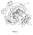
- FIG. 3 a detailed perspective view of an embodiment of a combustor head end 52 is illustrated having an end cover 54 with the plurality of fuel nozzles 14 attached to an end cover base surface 56 via sealing joints 58.
- the head end 52 routes air/fuel (e.g., the compressed air from the compressor 34 and/or the fuel through end cover 54) to each of the fuel nozzles 14, which may partially pre-mix the compressed air and fuel as an air-fuel mixture prior to entry into a combustion zone in the combustor 12.
- the fuel nozzles 14 may further comprise one or more swirl vanes configured to induce swirl in an air flow path, wherein each swirl vane includes fuel injection ports configured to inject fuel into the air flow path.
- an air/fuel inlet end 15 of the fuel nozzle 14 comprises a fuel nozzle base surface 62 with one or more air/fuel paths 70 and 80.
- the fuel nozzle base surface 62 comprises the surface of the fuel nozzle 14 that contacts the end cover base surface 56 of the combustor head end 52 when connected using the sealing joints 58 as illustrated in FIG. 3 .
- the end cover base surface 56 and the fuel nozzle base surface 62 can be joined to allow for the passage of air and/or fuel (“air/fuel”) through the combustor head end 52 and into the one or more air/fuel paths 70 and 80 of the fuel nozzles 14.
- the sealing joints 58 may comprise a plurality of bolt holes 64 disposed around the circumference of the fuel nozzle 14 that can align with complimentary holes in the end cover base surface 56 of the combustor head end 52 such that bolts may be used to connect the two pieces together as illustrated in FIG. 3 .
- any other suitable connection may additionally or alternative be used to connect the plurality of fuel nozzles 14 to the combustor head end 52 such that air and/or fuel may pass there between.
- the one or more air/fuel paths 70 and 80 can receive and direct the flow of air and/or fuel from the air/fuel inlet end 15 and through the fuel nozzle 14 for subsequent combustion.
- the one or more air/fuel paths 70 and 80 can thereby comprise any pathway or pathways that receive air and/or fuel from one end of the fuel nozzle 14 (e.g., about the fuel nozzle base surface 62) and directs it towards the other end of the fuel nozzle 14 for combustion.
- a first fuel path 70 can comprise one or more first air/fuel internal channels 72 that extend the length of the fuel nozzle 14 to direct the air and/or fuel towards the combustion end.
- the one or more first air/fuel internal channels 72 may be connected to a first plurality of air/fuel inlet orifices 76 via one or more first air/fuel connection segments 74.
- Each of the first plurality of air/fuel inlet orifices 76 can comprise an open cross-sectional area that allows for the passage of air and/or fuel into the fuel nozzle 14 (and more specifically, in towards the one or more first air/fuel internal channels 72).
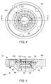
- the one or more first air/fuel connection segments 74 can connect the first plurality of air/fuel inlet orifices 76 to the one or more first air/fuel internal channels 72 as illustrated in FIG. 5 .
- the one or more first air/fuel connection segments 74 can thereby direct the incoming air and/or fuel from the first plurality of air/fuel inlet orifices 76 to the one or more first air fuel internal channels 72 when the two are not inherently in direct alignment (e.g., when the one or more first air/fuel internal channels 72 are more interior the fuel nozzle 14 than the first plurality of air/fuel inlet orifices 76 as illustrated in FIG. 5 .)
- the first plurality of air/fuel inlet orifices 76 can be aligned in a substantially circular orientation.
- the first plurality of air/fuel inlet orifices 76 can comprise any other orientation that allows for the passage of air and/or fuel for combustion such as, for example, a star-pattern orientation.
- FIG. 4 illustrates a first air/fuel path 70 with twelve air/fuel inlet orifices, it should be appreciated that the first air/fuel path 70 can alternatively comprise any number of first air/fuel inlet orifices 76 that allows for the passage of air and/or fuel for combustion.
- the fuel nozzle 14 may comprise a second air/fuel path 80.
- the second air/fuel path 80 can provide for an additional pathway system for air and/or fuel to pass through the fuel nozzle 14.
- the first air/fuel path 70 may be utilized for the passage of compressed air
- the second air/fuel path 80 may be utilized for the passage of combustible fuel (e.g., natural gas).
- the second air/fuel path 80 can comprise one or more second air/fuel internal channels 82 that extend the length of the fuel nozzle 14 to direct the air and/or fuel towards the combustion end.
- the one or more second air/fuel internal channels 82 may be connected to a second plurality of air/fuel inlet orifices 86 via one or more second air/fuel connection segments 84.
- Each of the second plurality of air/fuel inlet orifices 86 can comprise a second open cross-sectional area that allows for the passage of air and/or fuel into the fuel nozzle 14 (and more specifically, in towards the one or more second air/fuel internal channels 82).
- the first plurality of air/fuel inlet orifices 76 and the second plurality of air/fuel inlet orifices 86 may be concentric such that the plurality of air/fuel inlet orifices 76 and 86 form a series of rings (as illustrated in FIG. 4 ).
- the first plurality of air/fuel inlet orifices 76 and the second plurality of air/fuel inlet orifices 86 can comprise any other configurations and alignes with one another (e.g., wherein the location of the first plurality of air/fuel inlet orifices 76 is symmetrical with the location of the second plurality of air/fuel inlet orifices 86).
- the metered fuel nozzle 14 comprises a flow adjustment orifice system 100 to meter the amount of air and/or fuel passing from the combustor head end 52 into the fuel nozzle 14.
- the flow adjustment orifice system 100 comprises two metering plates 110 and 120 each comprising a plurality of metering orifices 111 and 121.
- the first metering plate 110 connects to an air/fuel inlet end 15 of the fuel nozzle 14 (e.g., on the fuel nozzle base surface 62) such that the first plurality of metering orifices 111 on the first metering plate 110 can align with the first plurality of air/fuel inlet orifices 76 of the first air/fuel path 70 in the fuel nozzle 14.
- the first metering plate 110 can comprise a first metering ring 110 with a void interior section 119.
- Such embodiments may provide the first plurality of metering orifices while reducing the area of contact between the first metering plate 110 and the fuel nozzle 14 thereby reducing the amount of material invested in the first metering plate 110.
- the first metering plate 110 can comprise other alternative structures such as square or circular plates (with or without a void interior section 119) depending on the size and shape constraints necessitated by the space between the combustor head end 52 and the fuel nozzle 14.
- the first metering plate 110 may directly attach to another part adjacent the fuel nozzle 14 so that the first metering plate 110 physically makes contact with (i.e., connects to) the fuel nozzle 14 when the fuel nozzle 14 is connected to that other part.
- the first metering plate 110 may attach to the combustor head end 52 so that when the fuel nozzle 14 is bolted to the combustor head end 52, the first metering plate 110 connects to the fuel nozzle 14 through physical contact.
- the first metering plate 110 of the flow adjustment orifice system 100 further comprises the first plurality of metering orifices 111.
- the first plurality of metering orifices 111 can each comprise an open pathway through the first metering plate 110 such that air and/or fuel may pass there through.
- Each of the first plurality of metering orifices 111 can comprise a specific geometry to regulate the amount of air and/or fuel that can pass through at any given time. For example, to allow a greater amount of air and/or fuel through the flow adjustment orifice system 100 (such as to increase the amount of combustion in the combustor 12), each of the first plurality of metering orifices 111 may comprise a relatively greater cross-sectional area.
- each of the first plurality of metering orifices 111 may comprise a relatively smaller cross-sectional area.
- each of the first plurality of metering orifices 111 may comprise a uniform cross-sectional profile (i.e., uniform size and shape so that the amount of air/fuel passing through each of the plurality of metering orifices is substantially uniform).
- each of the first plurality of metering orifices 111 may comprise the cross-sectional profile that matches the original open cross-sectional area for the first plurality of air/fuel inlet orifices 76.
- the placement of the first plurality of metering orifices 111 of the first metering plate 110 over the first plurality of air/fuel inlet orifices 76 may return the amount of air/fuel that flows through the fuel nozzle 14 to its original amount by reducing the open cross-sectional area of the first plurality of air/fuel inlet orifices 76 to their original condition.
- the first plurality of metering orifices 111 may comprise different sizes and shapes such that the first plurality of metering orifices 111 are non-uniform.
- the flow adjustment orifice system 100 comprises a plurality of metering plates, including a second metering plate 120 in addition to the first metering plate 110 as illustrated in FIGS. 4-7 .
- the second metering plate 120 connects to the air/fuel inlet end 15 of the fuel nozzle 14 and comprises a second plurality of metering orifices 121 disposed about the second metering plate 120 that align with the second plurality of air/fuel inlet orifices 86 on the air/fuel inlet end 15 of the fuel nozzle 14.
- at least one of the second plurality of metering orifices 121 can reduce a second open cross-sectional area for at least one of the second plurality of air/fuel inlet orifices 86.
- the fuel nozzle 14 comprising a first air/fuel path 70 (e.g., for compressed air) and a second air/fuel path 80 (e.g., for natural gas)
- the first plurality of metering orifices 111 of the first metering plate 110 can meter the amount of air/fuel flowing through the first air/fuel path 70 by reducing the open cross-sectional area for at least one of the first plurality of air/fuel inlet orifices 76
- the second plurality of metering orifices 121 of the second metering plate 120 can meter the amount of air/fuel flowing through the second air/fuel path 80 by reducing the second open cross-sectional area for at least one of the second plurality of air/fuel inlet orifices 86.
- the first metering plate 110 and the second metering plate 120 are aligned with one another (e.g., wherein the location of the first plurality of metering orifices 111 is symmetrical with the location of the second plurality of metering orifices 121).
- the first metering plate 110 and the second metering plate 120 may comprise concentrically aligned first and second metering rings such as illustrated in FIGS. 4-7 .
- first and second metering rings such as illustrated in FIGS. 4-7 .
- any other number of larger than two metering plates comprising any other various shapes may also be utilized.
- one or more of the metering plates may comprise a plurality of segments 122, 124 and 126 that are separable from one another.
- the plurality of segments 122, 124 and 126 may then be connected to the air/fuel inlet end 15 of the fuel nozzle 14 as separate pieces that come together once in place.
- Such embodiments may allow for the connection of a segmented metering plate (e.g., the second metering plate 120 illustrated in FIG. 6 ) to the air/fuel inlet end 15 of the fuel nozzle 14 when physical constraints prevent the connection of a solid metering plate (e.g., the first metering plate 110 illustrated in FIG. 6 ) by individually positioning and/or connecting the first segment 122, the second segment 124, and the third segment 126 (or any other number of segments) about the fuel nozzle 14 before connecting the plurality of segments 122, 124 and 126 to one another.
- a segmented metering plate e.g., the second metering plate 120 illustrated in FIG. 6
- the plurality of segments may interlock at a plurality of joints 123, 125 and 127.
- a first joint 123 may interconnect the first segment 122 to the second segment 124
- a second joint 125 may interconnect the second segment 124 to the third segment 126
- a third joint 127 may interconnect the third segment 126 to the first segment 122.
- the plurality of joints 123, 125 and 127 may comprise male and female pieces that combine with one another, as illustrated in FIG. 6 , or may otherwise comprise any other interlocking configuration.
- the plurality of segments 122, 124 and 126 may simply be disposed adjacent one another with no interlocking at the joints 123, 125 and 127 when connected to the fuel nozzle 14.
- FIG. 6 illustrates a first metering plate 110 comprising a solid construction, and a second metering plate 120 comprising a plurality of segments 122, 124 and 126) that are separable from one another
- any other combination of configurations may also be utilized (e.g., metering plates comprising a plurality of segments that are separable from one another, two solid metering plates, two metering plates each comprising a plurality of segments that are separable from one another, etc.).
- the second metering plate 120 illustrated in FIG. 6 comprises the first segment 122, the second segment 124 and the third segment 126, it should be appreciated that metering plates comprising a plurality of segments that are separable from one another may alternatively comprise any other number of segments.
- the flow adjustment orifice system 100 may be connected to the air/fuel inlet end 15 of the fuel nozzle 14 by any type of connection that fixes the pluralities of metering orifices (e.g., the first plurality of metering orifices 111 and the second plurality of metering orifices 121) of the metering plates in place relative to the pluralities of air/fuel inlet orifices of the fuel nozzle 14.
- the metering plates 110 and 120 may be connected to the fuel nozzle 14 via welds, stakes, screws, bolts, clasps, brackets or any other suitable connection mechanisms or combinations thereof.
- connection mechanisms may fix the flow adjustment orifice system 100 in place such that it does not move or rotate when air and/or fuel flows from the combustor head end 52 to the fuel nozzle 14 within the combustor 12 of the turbine system 10.
- the flow adjustment orifice system 100 (comprising at least the first metering plate 110 and the second metering plate 120, and any other additional metering plates) can comprise any material or materials that allow for its connection to the air/fuel inlet end 15 of the fuel nozzle 14 and the reduction of open cross-sectional area for the pluralities of air/fuel inlet orifices to meter the amount of air and/or fuel that flows there through.
- the metering plate(s) 110 and 120 may comprise a high strength alloy such as an Inconel alloy to provide strong physical properties sometimes required in the combustor 14 of the turbine system 10.
- the metering plate(s) 110 and 120 may comprise the same material as the fuel nozzle base surface 62 to provide more uniform material properties between the fuel nozzle 14 and the flow adjustment orifice system 100.
- any other materials may alternatively be used that allow for its connection to the air/fuel inlet end 15 of the fuel nozzle 14 and the reduction of open cross-sectional area for the pluralities of air/fuel inlet orifices 76 and 78.
- the pluralities of metering orifices can reduce the open cross-sectional area of one or more of the air/fuel inlet orifices. Such a connection can therefore meter the amount of air and or fuel that flows through the fuel nozzle without having to add additional material to or otherwise retool the original air/fuel path.
Landscapes
- Engineering & Computer Science (AREA)
- Chemical & Material Sciences (AREA)
- Combustion & Propulsion (AREA)
- Mechanical Engineering (AREA)
- General Engineering & Computer Science (AREA)
- Feeding And Controlling Fuel (AREA)
Applications Claiming Priority (1)
| Application Number | Priority Date | Filing Date | Title |
|---|---|---|---|
| US13/212,683 US8646703B2 (en) | 2011-08-18 | 2011-08-18 | Flow adjustment orifice systems for fuel nozzles |
Publications (2)
| Publication Number | Publication Date |
|---|---|
| EP2559940A1 EP2559940A1 (en) | 2013-02-20 |
| EP2559940B1 true EP2559940B1 (en) | 2015-10-14 |
Family
ID=46832218
Family Applications (1)
| Application Number | Title | Priority Date | Filing Date |
|---|---|---|---|
| EP12179935.7A Not-in-force EP2559940B1 (en) | 2011-08-18 | 2012-08-09 | Fuel nozzle for a gas turbine engine having with flow adjustment orifice system |
Country Status (4)
| Country | Link |
|---|---|
| US (1) | US8646703B2 (cg-RX-API-DMAC7.html) |
| EP (1) | EP2559940B1 (cg-RX-API-DMAC7.html) |
| JP (1) | JP5965777B2 (cg-RX-API-DMAC7.html) |
| CN (1) | CN102954494B (cg-RX-API-DMAC7.html) |
Families Citing this family (3)
| Publication number | Priority date | Publication date | Assignee | Title |
|---|---|---|---|---|
| US20150330636A1 (en) * | 2014-05-13 | 2015-11-19 | General Electric Company | System and method for control of combustion dynamics in combustion system |
| US10975703B2 (en) * | 2016-10-27 | 2021-04-13 | Raytheon Technologies Corporation | Additively manufactured component for a gas powered turbine |
| WO2018132185A1 (en) * | 2017-01-11 | 2018-07-19 | Siemens Energy, Inc. | Mechanical attachment of a fuel rocket on a support housing base |
Family Cites Families (17)
| Publication number | Priority date | Publication date | Assignee | Title |
|---|---|---|---|---|
| US2968925A (en) * | 1959-11-25 | 1961-01-24 | William E Blevans | Fuel nozzle head for anti-coking |
| US5685139A (en) | 1996-03-29 | 1997-11-11 | General Electric Company | Diffusion-premix nozzle for a gas turbine combustor and related method |
| GB2320755B (en) * | 1996-12-31 | 2000-03-29 | Westinghouse Electric Corp | Low nox combustor having dual fuel injection system |
| US6092363A (en) * | 1998-06-19 | 2000-07-25 | Siemens Westinghouse Power Corporation | Low Nox combustor having dual fuel injection system |
| GB9929601D0 (en) * | 1999-12-16 | 2000-02-09 | Rolls Royce Plc | A combustion chamber |
| GB0111788D0 (en) * | 2001-05-15 | 2001-07-04 | Rolls Royce Plc | A combustion chamber |
| JP4508474B2 (ja) * | 2001-06-07 | 2010-07-21 | 三菱重工業株式会社 | 燃焼器 |
| US6755024B1 (en) * | 2001-08-23 | 2004-06-29 | Delavan Inc. | Multiplex injector |
| US7093776B2 (en) | 2004-06-29 | 2006-08-22 | Delphi Technologies, Inc | Fuel injector nozzle atomizer having individual passages for inward directed accelerated cross-flow |
| US20070075158A1 (en) * | 2005-09-22 | 2007-04-05 | Pelletier Robert R | Nozzle assembly |
| JP4495179B2 (ja) | 2007-02-28 | 2010-06-30 | 三菱重工業株式会社 | 燃料ノズル装置、ガスタービンおよび燃料ノズル装置の制御方法 |
| US8276836B2 (en) * | 2007-07-27 | 2012-10-02 | General Electric Company | Fuel nozzle assemblies and methods |
| US20090320483A1 (en) | 2008-06-26 | 2009-12-31 | General Electric Company | Variable Orifice Plug for Turbine Fuel Nozzle |
| US8375548B2 (en) | 2009-10-07 | 2013-02-19 | Pratt & Whitney Canada Corp. | Fuel nozzle and method of repair |
| US8393156B2 (en) | 2009-11-09 | 2013-03-12 | Woodward, Inc. | Variable performance valve of a fuel nozzle for a turbine engine |
| US8484978B2 (en) | 2009-11-12 | 2013-07-16 | General Electric Company | Fuel nozzle assembly that exhibits a frequency different from a natural operating frequency of a gas turbine engine and method of assembling the same |
| US20110173983A1 (en) | 2010-01-15 | 2011-07-21 | General Electric Company | Premix fuel nozzle internal flow path enhancement |
-
2011
- 2011-08-18 US US13/212,683 patent/US8646703B2/en active Active
-
2012
- 2012-08-09 EP EP12179935.7A patent/EP2559940B1/en not_active Not-in-force
- 2012-08-13 JP JP2012179193A patent/JP5965777B2/ja active Active
- 2012-08-17 CN CN201210293709.6A patent/CN102954494B/zh active Active
Also Published As
| Publication number | Publication date |
|---|---|
| US20130043324A1 (en) | 2013-02-21 |
| EP2559940A1 (en) | 2013-02-20 |
| US8646703B2 (en) | 2014-02-11 |
| CN102954494A (zh) | 2013-03-06 |
| JP2013040757A (ja) | 2013-02-28 |
| CN102954494B (zh) | 2017-01-18 |
| JP5965777B2 (ja) | 2016-08-10 |
Similar Documents
| Publication | Publication Date | Title |
|---|---|---|
| US8850821B2 (en) | System for fuel injection in a fuel nozzle | |
| EP3450849B1 (en) | Fuel injector for a combustor of a gas turbine | |
| US8322143B2 (en) | System and method for injecting fuel | |
| US10215414B2 (en) | System and method having fuel nozzle | |
| US9115896B2 (en) | Fuel-air mixer for use with a combustor assembly | |
| US20120192565A1 (en) | System for premixing air and fuel in a fuel nozzle | |
| KR102543858B1 (ko) | 환형 유동로 아키텍쳐를 갖는 시스템 및 방법 | |
| EP2653783B1 (en) | Turbine combustor system having aerodynamic feed cap | |
| US8850822B2 (en) | System for pre-mixing in a fuel nozzle | |
| US11940152B2 (en) | Fuel circuit for a fuel injector | |
| US20110107765A1 (en) | Counter rotated gas turbine fuel nozzles | |
| EP2742291A1 (en) | System for injecting fuel in a gas turbine engine | |
| US10458655B2 (en) | Fuel nozzle assembly | |
| US10823420B2 (en) | Pilot nozzle with inline premixing | |
| EP2559940B1 (en) | Fuel nozzle for a gas turbine engine having with flow adjustment orifice system | |
| US20140238034A1 (en) | Turbomachine combustor assembly and method of operating a turbomachine |
Legal Events
| Date | Code | Title | Description |
|---|---|---|---|
| PUAI | Public reference made under article 153(3) epc to a published international application that has entered the european phase |
Free format text: ORIGINAL CODE: 0009012 |
|
| AK | Designated contracting states |
Kind code of ref document: A1 Designated state(s): AL AT BE BG CH CY CZ DE DK EE ES FI FR GB GR HR HU IE IS IT LI LT LU LV MC MK MT NL NO PL PT RO RS SE SI SK SM TR |
|
| AX | Request for extension of the european patent |
Extension state: BA ME |
|
| 17P | Request for examination filed |
Effective date: 20130820 |
|
| RBV | Designated contracting states (corrected) |
Designated state(s): AL AT BE BG CH CY CZ DE DK EE ES FI FR GB GR HR HU IE IS IT LI LT LU LV MC MK MT NL NO PL PT RO RS SE SI SK SM TR |
|
| GRAP | Despatch of communication of intention to grant a patent |
Free format text: ORIGINAL CODE: EPIDOSNIGR1 |
|
| INTG | Intention to grant announced |
Effective date: 20150319 |
|
| GRAS | Grant fee paid |
Free format text: ORIGINAL CODE: EPIDOSNIGR3 |
|
| GRAA | (expected) grant |
Free format text: ORIGINAL CODE: 0009210 |
|
| AK | Designated contracting states |
Kind code of ref document: B1 Designated state(s): AL AT BE BG CH CY CZ DE DK EE ES FI FR GB GR HR HU IE IS IT LI LT LU LV MC MK MT NL NO PL PT RO RS SE SI SK SM TR |
|
| REG | Reference to a national code |
Ref country code: GB Ref legal event code: FG4D |
|
| REG | Reference to a national code |
Ref country code: AT Ref legal event code: REF Ref document number: 755431 Country of ref document: AT Kind code of ref document: T Effective date: 20151015 Ref country code: CH Ref legal event code: EP |
|
| REG | Reference to a national code |
Ref country code: IE Ref legal event code: FG4D |
|
| REG | Reference to a national code |
Ref country code: DE Ref legal event code: R096 Ref document number: 602012011484 Country of ref document: DE |
|
| REG | Reference to a national code |
Ref country code: NL Ref legal event code: MP Effective date: 20151014 |
|
| REG | Reference to a national code |
Ref country code: LT Ref legal event code: MG4D |
|
| REG | Reference to a national code |
Ref country code: AT Ref legal event code: MK05 Ref document number: 755431 Country of ref document: AT Kind code of ref document: T Effective date: 20151014 |
|
| PG25 | Lapsed in a contracting state [announced via postgrant information from national office to epo] |
Ref country code: NO Free format text: LAPSE BECAUSE OF FAILURE TO SUBMIT A TRANSLATION OF THE DESCRIPTION OR TO PAY THE FEE WITHIN THE PRESCRIBED TIME-LIMIT Effective date: 20160114 Ref country code: IS Free format text: LAPSE BECAUSE OF FAILURE TO SUBMIT A TRANSLATION OF THE DESCRIPTION OR TO PAY THE FEE WITHIN THE PRESCRIBED TIME-LIMIT Effective date: 20160214 Ref country code: IT Free format text: LAPSE BECAUSE OF FAILURE TO SUBMIT A TRANSLATION OF THE DESCRIPTION OR TO PAY THE FEE WITHIN THE PRESCRIBED TIME-LIMIT Effective date: 20151014 Ref country code: NL Free format text: LAPSE BECAUSE OF FAILURE TO SUBMIT A TRANSLATION OF THE DESCRIPTION OR TO PAY THE FEE WITHIN THE PRESCRIBED TIME-LIMIT Effective date: 20151014 Ref country code: LT Free format text: LAPSE BECAUSE OF FAILURE TO SUBMIT A TRANSLATION OF THE DESCRIPTION OR TO PAY THE FEE WITHIN THE PRESCRIBED TIME-LIMIT Effective date: 20151014 Ref country code: ES Free format text: LAPSE BECAUSE OF FAILURE TO SUBMIT A TRANSLATION OF THE DESCRIPTION OR TO PAY THE FEE WITHIN THE PRESCRIBED TIME-LIMIT Effective date: 20151014 Ref country code: HR Free format text: LAPSE BECAUSE OF FAILURE TO SUBMIT A TRANSLATION OF THE DESCRIPTION OR TO PAY THE FEE WITHIN THE PRESCRIBED TIME-LIMIT Effective date: 20151014 |
|
| PG25 | Lapsed in a contracting state [announced via postgrant information from national office to epo] |
Ref country code: GR Free format text: LAPSE BECAUSE OF FAILURE TO SUBMIT A TRANSLATION OF THE DESCRIPTION OR TO PAY THE FEE WITHIN THE PRESCRIBED TIME-LIMIT Effective date: 20160115 Ref country code: SE Free format text: LAPSE BECAUSE OF FAILURE TO SUBMIT A TRANSLATION OF THE DESCRIPTION OR TO PAY THE FEE WITHIN THE PRESCRIBED TIME-LIMIT Effective date: 20151014 Ref country code: AT Free format text: LAPSE BECAUSE OF FAILURE TO SUBMIT A TRANSLATION OF THE DESCRIPTION OR TO PAY THE FEE WITHIN THE PRESCRIBED TIME-LIMIT Effective date: 20151014 Ref country code: RS Free format text: LAPSE BECAUSE OF FAILURE TO SUBMIT A TRANSLATION OF THE DESCRIPTION OR TO PAY THE FEE WITHIN THE PRESCRIBED TIME-LIMIT Effective date: 20151014 Ref country code: PL Free format text: LAPSE BECAUSE OF FAILURE TO SUBMIT A TRANSLATION OF THE DESCRIPTION OR TO PAY THE FEE WITHIN THE PRESCRIBED TIME-LIMIT Effective date: 20151014 Ref country code: LV Free format text: LAPSE BECAUSE OF FAILURE TO SUBMIT A TRANSLATION OF THE DESCRIPTION OR TO PAY THE FEE WITHIN THE PRESCRIBED TIME-LIMIT Effective date: 20151014 Ref country code: PT Free format text: LAPSE BECAUSE OF FAILURE TO SUBMIT A TRANSLATION OF THE DESCRIPTION OR TO PAY THE FEE WITHIN THE PRESCRIBED TIME-LIMIT Effective date: 20160215 Ref country code: FI Free format text: LAPSE BECAUSE OF FAILURE TO SUBMIT A TRANSLATION OF THE DESCRIPTION OR TO PAY THE FEE WITHIN THE PRESCRIBED TIME-LIMIT Effective date: 20151014 |
|
| REG | Reference to a national code |
Ref country code: DE Ref legal event code: R097 Ref document number: 602012011484 Country of ref document: DE |
|
| PG25 | Lapsed in a contracting state [announced via postgrant information from national office to epo] |
Ref country code: CZ Free format text: LAPSE BECAUSE OF FAILURE TO SUBMIT A TRANSLATION OF THE DESCRIPTION OR TO PAY THE FEE WITHIN THE PRESCRIBED TIME-LIMIT Effective date: 20151014 |
|
| PLBE | No opposition filed within time limit |
Free format text: ORIGINAL CODE: 0009261 |
|
| STAA | Information on the status of an ep patent application or granted ep patent |
Free format text: STATUS: NO OPPOSITION FILED WITHIN TIME LIMIT |
|
| PG25 | Lapsed in a contracting state [announced via postgrant information from national office to epo] |
Ref country code: SK Free format text: LAPSE BECAUSE OF FAILURE TO SUBMIT A TRANSLATION OF THE DESCRIPTION OR TO PAY THE FEE WITHIN THE PRESCRIBED TIME-LIMIT Effective date: 20151014 Ref country code: SM Free format text: LAPSE BECAUSE OF FAILURE TO SUBMIT A TRANSLATION OF THE DESCRIPTION OR TO PAY THE FEE WITHIN THE PRESCRIBED TIME-LIMIT Effective date: 20151014 Ref country code: RO Free format text: LAPSE BECAUSE OF FAILURE TO SUBMIT A TRANSLATION OF THE DESCRIPTION OR TO PAY THE FEE WITHIN THE PRESCRIBED TIME-LIMIT Effective date: 20151014 Ref country code: DK Free format text: LAPSE BECAUSE OF FAILURE TO SUBMIT A TRANSLATION OF THE DESCRIPTION OR TO PAY THE FEE WITHIN THE PRESCRIBED TIME-LIMIT Effective date: 20151014 Ref country code: EE Free format text: LAPSE BECAUSE OF FAILURE TO SUBMIT A TRANSLATION OF THE DESCRIPTION OR TO PAY THE FEE WITHIN THE PRESCRIBED TIME-LIMIT Effective date: 20151014 |
|
| 26N | No opposition filed |
Effective date: 20160715 |
|
| PG25 | Lapsed in a contracting state [announced via postgrant information from national office to epo] |
Ref country code: SI Free format text: LAPSE BECAUSE OF FAILURE TO SUBMIT A TRANSLATION OF THE DESCRIPTION OR TO PAY THE FEE WITHIN THE PRESCRIBED TIME-LIMIT Effective date: 20151014 |
|
| PG25 | Lapsed in a contracting state [announced via postgrant information from national office to epo] |
Ref country code: BE Free format text: LAPSE BECAUSE OF FAILURE TO SUBMIT A TRANSLATION OF THE DESCRIPTION OR TO PAY THE FEE WITHIN THE PRESCRIBED TIME-LIMIT Effective date: 20151014 |
|
| REG | Reference to a national code |
Ref country code: DE Ref legal event code: R119 Ref document number: 602012011484 Country of ref document: DE |
|
| PG25 | Lapsed in a contracting state [announced via postgrant information from national office to epo] |
Ref country code: MC Free format text: LAPSE BECAUSE OF FAILURE TO SUBMIT A TRANSLATION OF THE DESCRIPTION OR TO PAY THE FEE WITHIN THE PRESCRIBED TIME-LIMIT Effective date: 20151014 |
|
| GBPC | Gb: european patent ceased through non-payment of renewal fee |
Effective date: 20160809 |
|
| REG | Reference to a national code |
Ref country code: FR Ref legal event code: ST Effective date: 20170428 |
|
| REG | Reference to a national code |
Ref country code: IE Ref legal event code: MM4A |
|
| PG25 | Lapsed in a contracting state [announced via postgrant information from national office to epo] |
Ref country code: FR Free format text: LAPSE BECAUSE OF NON-PAYMENT OF DUE FEES Effective date: 20160831 Ref country code: IE Free format text: LAPSE BECAUSE OF NON-PAYMENT OF DUE FEES Effective date: 20160809 Ref country code: GB Free format text: LAPSE BECAUSE OF NON-PAYMENT OF DUE FEES Effective date: 20160809 Ref country code: DE Free format text: LAPSE BECAUSE OF NON-PAYMENT OF DUE FEES Effective date: 20170301 |
|
| PG25 | Lapsed in a contracting state [announced via postgrant information from national office to epo] |
Ref country code: LU Free format text: LAPSE BECAUSE OF NON-PAYMENT OF DUE FEES Effective date: 20160809 |
|
| PGFP | Annual fee paid to national office [announced via postgrant information from national office to epo] |
Ref country code: CH Payment date: 20170827 Year of fee payment: 6 |
|
| PG25 | Lapsed in a contracting state [announced via postgrant information from national office to epo] |
Ref country code: HU Free format text: LAPSE BECAUSE OF FAILURE TO SUBMIT A TRANSLATION OF THE DESCRIPTION OR TO PAY THE FEE WITHIN THE PRESCRIBED TIME-LIMIT; INVALID AB INITIO Effective date: 20120809 Ref country code: CY Free format text: LAPSE BECAUSE OF FAILURE TO SUBMIT A TRANSLATION OF THE DESCRIPTION OR TO PAY THE FEE WITHIN THE PRESCRIBED TIME-LIMIT Effective date: 20151014 |
|
| PG25 | Lapsed in a contracting state [announced via postgrant information from national office to epo] |
Ref country code: TR Free format text: LAPSE BECAUSE OF FAILURE TO SUBMIT A TRANSLATION OF THE DESCRIPTION OR TO PAY THE FEE WITHIN THE PRESCRIBED TIME-LIMIT Effective date: 20151014 Ref country code: MT Free format text: LAPSE BECAUSE OF NON-PAYMENT OF DUE FEES Effective date: 20160831 Ref country code: MK Free format text: LAPSE BECAUSE OF FAILURE TO SUBMIT A TRANSLATION OF THE DESCRIPTION OR TO PAY THE FEE WITHIN THE PRESCRIBED TIME-LIMIT Effective date: 20151014 |
|
| PG25 | Lapsed in a contracting state [announced via postgrant information from national office to epo] |
Ref country code: BG Free format text: LAPSE BECAUSE OF FAILURE TO SUBMIT A TRANSLATION OF THE DESCRIPTION OR TO PAY THE FEE WITHIN THE PRESCRIBED TIME-LIMIT Effective date: 20151014 |
|
| PG25 | Lapsed in a contracting state [announced via postgrant information from national office to epo] |
Ref country code: AL Free format text: LAPSE BECAUSE OF FAILURE TO SUBMIT A TRANSLATION OF THE DESCRIPTION OR TO PAY THE FEE WITHIN THE PRESCRIBED TIME-LIMIT Effective date: 20151014 |
|
| REG | Reference to a national code |
Ref country code: CH Ref legal event code: PL |
|
| PG25 | Lapsed in a contracting state [announced via postgrant information from national office to epo] |
Ref country code: LI Free format text: LAPSE BECAUSE OF NON-PAYMENT OF DUE FEES Effective date: 20180831 Ref country code: CH Free format text: LAPSE BECAUSE OF NON-PAYMENT OF DUE FEES Effective date: 20180831 |