EP2559920A1 - Leaf seal - Google Patents
Leaf seal Download PDFInfo
- Publication number
- EP2559920A1 EP2559920A1 EP12178790A EP12178790A EP2559920A1 EP 2559920 A1 EP2559920 A1 EP 2559920A1 EP 12178790 A EP12178790 A EP 12178790A EP 12178790 A EP12178790 A EP 12178790A EP 2559920 A1 EP2559920 A1 EP 2559920A1
- Authority
- EP
- European Patent Office
- Prior art keywords
- leaf
- spacer
- sheet
- section
- seal
- Prior art date
- Legal status (The legal status is an assumption and is not a legal conclusion. Google has not performed a legal analysis and makes no representation as to the accuracy of the status listed.)
- Granted
Links
- 125000006850 spacer group Chemical group 0.000 claims abstract description 59
- 238000000034 method Methods 0.000 claims abstract description 32
- 230000008569 process Effects 0.000 claims abstract description 29
- 239000000463 material Substances 0.000 claims abstract description 20
- 230000000694 effects Effects 0.000 claims abstract description 9
- 229910045601 alloy Inorganic materials 0.000 claims description 6
- 239000000956 alloy Substances 0.000 claims description 6
- 238000005219 brazing Methods 0.000 claims description 4
- 239000007769 metal material Substances 0.000 claims description 2
- 238000010276 construction Methods 0.000 claims 2
- 230000015572 biosynthetic process Effects 0.000 description 4
- 230000000750 progressive effect Effects 0.000 description 4
- 238000007789 sealing Methods 0.000 description 4
- 238000005452 bending Methods 0.000 description 3
- 238000002485 combustion reaction Methods 0.000 description 3
- 230000006835 compression Effects 0.000 description 3
- 238000007906 compression Methods 0.000 description 3
- 238000009826 distribution Methods 0.000 description 3
- 239000007789 gas Substances 0.000 description 3
- 238000001259 photo etching Methods 0.000 description 3
- 230000001141 propulsive effect Effects 0.000 description 3
- 239000002699 waste material Substances 0.000 description 3
- 238000005530 etching Methods 0.000 description 2
- 230000004048 modification Effects 0.000 description 2
- 238000012986 modification Methods 0.000 description 2
- ORQBXQOJMQIAOY-UHFFFAOYSA-N nobelium Chemical compound [No] ORQBXQOJMQIAOY-UHFFFAOYSA-N 0.000 description 2
- 230000002028 premature Effects 0.000 description 2
- 230000006903 response to temperature Effects 0.000 description 2
- 230000003068 static effect Effects 0.000 description 2
- UFHFLCQGNIYNRP-UHFFFAOYSA-N Hydrogen Chemical compound [H][H] UFHFLCQGNIYNRP-UHFFFAOYSA-N 0.000 description 1
- 239000000853 adhesive Substances 0.000 description 1
- 230000001070 adhesive effect Effects 0.000 description 1
- 230000000712 assembly Effects 0.000 description 1
- 238000000429 assembly Methods 0.000 description 1
- 230000004888 barrier function Effects 0.000 description 1
- 239000000446 fuel Substances 0.000 description 1
- 239000001257 hydrogen Substances 0.000 description 1
- 229910052739 hydrogen Inorganic materials 0.000 description 1
- 238000005304 joining Methods 0.000 description 1
- 238000003754 machining Methods 0.000 description 1
- 239000002184 metal Substances 0.000 description 1
- 238000005459 micromachining Methods 0.000 description 1
- 239000000203 mixture Substances 0.000 description 1
- 230000003014 reinforcing effect Effects 0.000 description 1
- 239000010935 stainless steel Substances 0.000 description 1
- 229910001220 stainless steel Inorganic materials 0.000 description 1
- 229910000601 superalloy Inorganic materials 0.000 description 1
- 230000003746 surface roughness Effects 0.000 description 1
- 238000003466 welding Methods 0.000 description 1
Images



Classifications
-
- F—MECHANICAL ENGINEERING; LIGHTING; HEATING; WEAPONS; BLASTING
- F16—ENGINEERING ELEMENTS AND UNITS; GENERAL MEASURES FOR PRODUCING AND MAINTAINING EFFECTIVE FUNCTIONING OF MACHINES OR INSTALLATIONS; THERMAL INSULATION IN GENERAL
- F16J—PISTONS; CYLINDERS; SEALINGS
- F16J15/00—Sealings
- F16J15/16—Sealings between relatively-moving surfaces
- F16J15/32—Sealings between relatively-moving surfaces with elastic sealings, e.g. O-rings
- F16J15/3284—Sealings between relatively-moving surfaces with elastic sealings, e.g. O-rings characterised by their structure; Selection of materials
- F16J15/3292—Lamellar structures
-
- F—MECHANICAL ENGINEERING; LIGHTING; HEATING; WEAPONS; BLASTING
- F01—MACHINES OR ENGINES IN GENERAL; ENGINE PLANTS IN GENERAL; STEAM ENGINES
- F01D—NON-POSITIVE DISPLACEMENT MACHINES OR ENGINES, e.g. STEAM TURBINES
- F01D11/00—Preventing or minimising internal leakage of working-fluid, e.g. between stages
- F01D11/003—Preventing or minimising internal leakage of working-fluid, e.g. between stages by packing rings; Mechanical seals
-
- F—MECHANICAL ENGINEERING; LIGHTING; HEATING; WEAPONS; BLASTING
- F05—INDEXING SCHEMES RELATING TO ENGINES OR PUMPS IN VARIOUS SUBCLASSES OF CLASSES F01-F04
- F05D—INDEXING SCHEME FOR ASPECTS RELATING TO NON-POSITIVE-DISPLACEMENT MACHINES OR ENGINES, GAS-TURBINES OR JET-PROPULSION PLANTS
- F05D2240/00—Components
- F05D2240/55—Seals
- F05D2240/57—Leaf seals
-
- F—MECHANICAL ENGINEERING; LIGHTING; HEATING; WEAPONS; BLASTING
- F05—INDEXING SCHEMES RELATING TO ENGINES OR PUMPS IN VARIOUS SUBCLASSES OF CLASSES F01-F04
- F05D—INDEXING SCHEME FOR ASPECTS RELATING TO NON-POSITIVE-DISPLACEMENT MACHINES OR ENGINES, GAS-TURBINES OR JET-PROPULSION PLANTS
- F05D2240/00—Components
- F05D2240/55—Seals
- F05D2240/59—Lamellar seals
-
- Y—GENERAL TAGGING OF NEW TECHNOLOGICAL DEVELOPMENTS; GENERAL TAGGING OF CROSS-SECTIONAL TECHNOLOGIES SPANNING OVER SEVERAL SECTIONS OF THE IPC; TECHNICAL SUBJECTS COVERED BY FORMER USPC CROSS-REFERENCE ART COLLECTIONS [XRACs] AND DIGESTS
- Y10—TECHNICAL SUBJECTS COVERED BY FORMER USPC
- Y10T—TECHNICAL SUBJECTS COVERED BY FORMER US CLASSIFICATION
- Y10T29/00—Metal working
- Y10T29/49—Method of mechanical manufacture
- Y10T29/49316—Impeller making
- Y10T29/4932—Turbomachine making
-
- Y—GENERAL TAGGING OF NEW TECHNOLOGICAL DEVELOPMENTS; GENERAL TAGGING OF CROSS-SECTIONAL TECHNOLOGIES SPANNING OVER SEVERAL SECTIONS OF THE IPC; TECHNICAL SUBJECTS COVERED BY FORMER USPC CROSS-REFERENCE ART COLLECTIONS [XRACs] AND DIGESTS
- Y10—TECHNICAL SUBJECTS COVERED BY FORMER USPC
- Y10T—TECHNICAL SUBJECTS COVERED BY FORMER US CLASSIFICATION
- Y10T29/00—Metal working
- Y10T29/49—Method of mechanical manufacture
- Y10T29/49826—Assembling or joining
-
- Y—GENERAL TAGGING OF NEW TECHNOLOGICAL DEVELOPMENTS; GENERAL TAGGING OF CROSS-SECTIONAL TECHNOLOGIES SPANNING OVER SEVERAL SECTIONS OF THE IPC; TECHNICAL SUBJECTS COVERED BY FORMER USPC CROSS-REFERENCE ART COLLECTIONS [XRACs] AND DIGESTS
- Y10—TECHNICAL SUBJECTS COVERED BY FORMER USPC
- Y10T—TECHNICAL SUBJECTS COVERED BY FORMER US CLASSIFICATION
- Y10T29/00—Metal working
- Y10T29/49—Method of mechanical manufacture
- Y10T29/49826—Assembling or joining
- Y10T29/49908—Joining by deforming
-
- Y—GENERAL TAGGING OF NEW TECHNOLOGICAL DEVELOPMENTS; GENERAL TAGGING OF CROSS-SECTIONAL TECHNOLOGIES SPANNING OVER SEVERAL SECTIONS OF THE IPC; TECHNICAL SUBJECTS COVERED BY FORMER USPC CROSS-REFERENCE ART COLLECTIONS [XRACs] AND DIGESTS
- Y10—TECHNICAL SUBJECTS COVERED BY FORMER USPC
- Y10T—TECHNICAL SUBJECTS COVERED BY FORMER US CLASSIFICATION
- Y10T29/00—Metal working
- Y10T29/49—Method of mechanical manufacture
- Y10T29/49826—Assembling or joining
- Y10T29/49945—Assembling or joining by driven force fit
Definitions
- the present invention relates to a process for forming a leaf-spacer pair for use in a leaf seal.
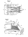
- a ducted fan gas turbine engine generally indicated at 10 has a principal and rotational axis X-X.
- the engine comprises, in axial flow series, an air intake 11, a propulsive fan 12, an intermediate pressure compressor 13, a high-pressure compressor 14, combustion equipment 15, a high-pressure turbine 16, and intermediate pressure turbine 17, a low-pressure turbine 18 and a core engine exhaust nozzle 19.
- a nacelle 21 generally surrounds the engine 10 and defines the intake 11, a bypass duct 22 and a bypass exhaust nozzle 23.
- the gas turbine engine 10 works in a conventional manner so that air entering the intake 11 is accelerated by the fan 12 to produce two air flows: a first air flow A into the intermediate pressure compressor 13 and a second air flow B which passes through the bypass duct 22 to provide propulsive thrust.
- the intermediate pressure compressor 13 compresses the air flow A directed into it before delivering that air to the high pressure compressor 14 where further compression takes place.
- the compressed air exhausted from the high-pressure compressor 14 is directed into the combustion equipment 15 where it is mixed with fuel and the mixture combusted.
- the resultant hot combustion products then expand through, and thereby drive the high, intermediate and low-pressure turbines 16, 17, 18 before being exhausted through the nozzle 19 to provide additional propulsive thrust.
- the high, intermediate and low-pressure turbines respectively drive the high and intermediate pressure compressors 14, 13 and the fan 12 by suitable interconnecting shafts.
- Leaf seals are formed from sections of leaf material appropriately presented in order to create a seal surface from juxtaposed leaf edges of respective leaves in an assembly.
- the leaves are arranged circumferentially about a rotating shaft in order to present the leaf edges and therefore the seal surface towards that shaft in order to provide a seal barrier.
- spacer members are provided between each leaf in order to correctly arrange the seal elements for presentation of the leaf edges and therefore the seal surface. These spacers may be independent components or integrally formed with each leaf. The leaf edges and so the seal surface effectively floats upwards and downwards relative to a rotating surface.
- leaf seals may be used to form a seal between a static component and a rotating component, between two relatively rotating components, or even between two static components in order to maintain a relatively high pressure on one side of the seal and relatively low pressure on the other.
- Figure 2 which shows schematically, for example, a cut-away perspective view of a portion of a leaf seal assembly 31 comprises seal elements 32 extending from spacer elements 33 secured in a housing comprising a backing ring 34 with side plates 35.
- the seal leaf elements 32 present leaf edges 36 towards a surface 37 of a rotating component generally rotating in the direction depicted by arrowhead 38.
- the leaves 32, and in particular the leaf edges 36 of the leaves 32 act against the surface 37 in order to create a seal across the assembly 31.
- Each leaf section 32 is generally compliant in order to adjust with rotation of the surface 11 to ensure that a good sealing effect is created.
- the spacers 33 are generally required in order to ensure that flexibility is available to appropriately present the leaf seal elements 32 towards the surface 37 which, as illustrated, is generally with an inclined angle between them.
- leaf seals are relatively complex in terms of the number of leaves in the assembly and the importance of correctly aligning and spacing leaves in order to achieve best effect. Formation of leaf seals using a pleated band or strip has been proposed and is described in WO 015933802 .
- a metal strip is essentially stamped in order to define a plurality of leaf sealing elements and the strip or band then folded in order to create by concertina compression a leaf seal which is then mounted within a housing for presentation towards a surface to be sealed.
- leaf seals depend upon the space in between the leaf edges in order to be effective. If leaf seal edges are not effectively suspended, then either a large gap will open up under the leaves or a heavy contact will occur between the leaf edges and the shaft, both of which will lead to an ineffective seal.
- EP A 1878955 proposes a method of forming leaf seals comprising etching leaves in a strip, each leaf being etched at a tilt angle to create a step when each leaf is concertina folded against its adjacent neighbour, and folding the strip whereby the leaves are juxtaposed to present a seal surface formed by each leaf edge of each leaf.
- EP A 1878955 also proposes a method of forming leaf seals comprising etching leaves in a strip, each leaf having a spacer section, and spacers for the leaves being defined by removal of at least part of the remainder of at least some of the leaves.
- FIG 3 shows schematically a strip 50 appropriately photochemically machined in order to create respective leaf seal sections 51.
- Each leaf seal section 51 comprises a seal element leaf 52 and a root section 53. Due to the tilt angle L, which is exaggerated for convenient demonstration, there are waste areas in relation to sides 54 and top 55 which are removed as required.
- the root sections 53 are of thicker section than the operational leaf seal elements 52 and this is achieved in the strip 50 through appropriate machining such as photo-chemical machining of the leaf seal elements 52.
- a fold section 56 is provided between each leaf section 51 to enable a zigzag fold to be performed.
- the fold sections 56 can also be thinned to reduce stresses on bending.
- Figure 4 illustrates schematically folding of the leaf sections formed by provision of the folded sections 56 and the removal of the waste areas 54, 55 from the strip 50 depicted in Figure 3 .
- the root sections 53 are still attached at the fold lines 56 in a staggered configuration.
- a zigzag fold can be provided about these sections 56 in order to move through the stage depicted in Figure 4(a) to a compressed stack or tuft 60 with juxtaposed root sections 53 presenting the seal elements 52 at an appropriate lay angle as depicted in Figure 4(b) .
- the stack 60 leans such that bottom leaf edges 61 are appropriately presented in use relative to a seal surface.
- each root section 53 typically a hole 62 is provided in each root section 53 in order to create a plenum chamber by the juxtaposed root sections 53 in order to achieve the desired pressure distribution about a seal assembly in use.
- leaf elements 81 are again defined between fold sections 86, but alternate leaf sections 81 a, 81 b are arranged such that in leaf section 81 a a root section 83a is provided along with a leaf seal element 82, whilst in adjacent leaf section 81 b the whole of the strip (i.e. the area 85 as well as area 87) other than a spacer 83b between root sections 83a to which seal elements 82 are attached.
- This allows larger inter-leaf gaps to be formed.
- a zigzag fold is then performed about fold edges 86 in order to create a compressed stack 90 which has alternating root section 83a and spacers 83b juxtaposed to each other. Again, a pressure equalisation plenum chamber is created by holes 92 in each root section 83a and spacer 83b which extends annularly about the seal assembly to achieve sealing efficiency.
- Leaf-spacer folded pairs may also be provided. A multitude of such pairs can be assembled into a leaf seal assembly.
- a double side arm arrangement has a root section 103a with a hole 106 to provide a plenum chamber for pressure distribution in the eventual seal assembly. Again folded sections 101 are provided such that there is a step between the spacer 103a to which a seal element 102 is secured and a spacer 103b.
- the double arm arrangement depicted in Figure 7(a) there is an arm 100 in the root section 103a either side of the element 102.
- the stepped alignment 104 is again determined by the tilt angle in the strip from which the leaf-spacer folded pair is formed.
- FIG. 7(b) a single arm leaf-spacer folded pair is depicted.
- a root section 203a is provided to which a seal element 202 is secured with an aperture 206 in order to form a plenum chamber for pressure distribution in use.
- a spacer 203b is provided between the root section 203a and a spacer 203b.
- a fold section 201 in between the root section 203a and the spacer 203b in order to form the leaf-spacer folded pair for assembly into a leaf seal assembly as described later.
- Both the arrangements of leaf-spacer folded pairs depicted in Figure 7 can be appropriately photochemically machined from a sheet, and both may incorporate reinforcing 107, 207 to facilitate assembly strengths.
- leaf stacks and leaf-spacer folded pairs described above are fitted into an assembly jig and joined together e.g. by a welding or brazing processes, as described in EP A 1878955 , to form complete leaf seal assemblies.
- the folding sections are generally machined away.
- Figure 8 illustrates an exaggerated fold between two leaf sections.
- leaf section 41 a is forced into abutment and brazed or welded or otherwise secured in position against leaf section 41 b.
- the folding section 45 is thinned and as depicted rounded to reduce stressing.
- the section to the left of broken line 40 can be machined away after brazing the leaf sections 41 a, 41 b together.
- An aim of the present invention is to provide performance improvements in leaf seals.
- a first aspect of the present invention provides a process for forming a leaf-spacer pair for use in a leaf seal which effects a seal between two components, wherein the process includes the steps of:
- a second aspect of the present invention provides a process for forming a stack of leaves for use in a leaf seal, the process including:
- a third aspect of the present invention provides a leaf-spacer pair for use in a leaf seal, the leaf-spacer pair being formed by the process of the first aspect.
- the third aspect provides a leaf-spacer pair for use in a leaf seal which effects a seal between two components, the leaf-spacer pair having a leaf section which, in the leaf seal, maintains wiping contact with one of the components, and a root section which, in the leaf seal, is fixed relative to the other component and from which the leaf section extends, the leaf-spacer pair further having a spacer, wherein the leaf section and the root section are formed from a first sheet of material of substantially uniform thickness, the spacer is formed from a second sheet of material, and the spacer is fastened to the root section such that the spacer overlays the root section and remains fixed relative thereto on handling of the leaf-spacer pair.
- a fourth aspect of the present invention provides a stack of leaves for use in a leaf seal, the stack being formed by the process of the second aspect.
- the fourth aspect provides a stack of leaves for use in a leaf seal, the stack including a plurality of leaf-spacer pairs of the third aspect combined into a stack in which the leaf sections are arranged face-to-face and the spacers interpose between the root sections to space the leaf sections a controlled distance apart.
- a fifth aspect of the present invention provides a leaf seal including one or more leaf-spacer pairs of the third aspect or one or more stacks of leaves of the fourth aspect.
- the present invention is at least partly based on a realisation that thinned leaf sections can have problems of poor surface finish and premature leaf section failure.
- controlled distances between leaf sections can be achieved by providing separate spacers, and allowing leaf sections to retain the original sheet thickness.
- a leaf-spacer pair in which the spacer remains fixed relative to the root portion on handling of the pair facilitates formation of leaf stacks from such pairs and increases flexibility in the material choice and thickness of the spacer.
- the root section can be thinned, e.g. by photochemical machining or micromachining, to provide further control of the distance between the leaf sections in a stack.
- the root section can be thinned, e.g. by photochemical machining or micromachining, to provide further control of the distance between the leaf sections in a stack.
- photochemical machining or micromachining e.g. by photochemical machining or micromachining
- the spacer may be mechanically fastened to the root section.
- the mechanical fastening may conveniently include a press-fit fastening arrangement. Additionally or alternatively, the mechanical fastening may include folding the spacer around the root section to fasten it thereto.
- step (c) the spacer may be adhesively fastened to the root section.
- the first sheet is preferably a rolled sheet and the leaf section retains the as-rolled finish.
- the first sheet can be a cold-rolled sheet.
- a cold-rolled finish has been found to improve leaf section performance and reliability.
- the first sheet may be formed from an Ni-based or a Co-based alloy, such as a superalloy.
- the first sheet may be formed from an Fe-based alloy, such as a stainless steel.
- the second sheet can be formed from the same material as the first sheet. Alternatively, however, the second sheet can be formed from a different material to the first sheet.
- the material of the second sheet can have a different coefficient of thermal expansion to the material of the first sheet, allowing a leaf seal formed from such leaf-spacer pairs to exploit differential thermal effects in order to e.g. expand or contract the distance between leaf sections, and hence the effectiveness of the seal, in response to temperature.
- the second sheet can be made from a non-metallic material or a plastic.
- the second sheet may be in a wedge shape to facilitate the creation of a circular seal.
- the second sheet may be pre-stamped to create accurately controlled spacer shape (e.g. wedge) and/or thickness.
- the second sheet may incorporate braze alloy to facilitate the brazing of the seal.
- the second sheet may be made of two (or more) sheets which may or may not be similar. If they are dissimilar with different coefficients of thermal expansion then they may facilitate the leaf-spacer pairs to exploit thermal effects in response to temperature.
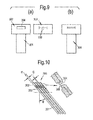
- Figure 9 shows schematically progressive stages (a) and (b) in the formation of a leaf-spacer pair according to a first embodiment of the present invention.
- Figure 9(a) shows a leaf section 301 and a root section 302 from which the leaf section extends, both stamped from a cold-rolled first sheet of material of substantially uniform thickness. A central hole 304 is cut out of the root section.
- Figure 9(a) also shows a separate spacer 303 from a second sheet of material. Central cuts in the spacer produce a pair of tabs 305.
- the spacer is approximately the same size as the root section, but may have a different thickness.
- leaf-spacer pairs can be formed in the same way, and, as shown in Figure 10 , these can be combined into a stack 306 of lay angle ⁇ in which leaf sections 301 are arranged face-to-face and the spacers 303 interpose between the root sections 302 to space the leaf sections a controlled distance apart, the leaf-spacer pairs subsequently being brazed or welded together in the stack.
- the mechanically fastened spacers remain securely fixed to their respective root sections during the stacking procedure.
- the thickness t1 of the first sheet from which the leaf and root sections are formed defines the thickness of the leaf sections in the stack, and the thickness t2 of the second sheet from which the spacers are formed determines the spacing between the leaf sections.
- the central hole 304 and the opening formed by the bent tabs 305 can combine in the stack to form a pressure equalisation plenum chamber. Further adjustment to the spacing between the leaf sections can be made by bending along the join lines between the leaf sections and the root sections. As shown in Figure 11 , which is a schematic side view of a further leaf stack 406, this can produce an adjustment, ⁇ , in the lay angle ⁇ of the stack.
- Thinning by photochemical machining can be associated with premature leaf section failure (e.g. due to surface roughness and hydrogen embrittlement).
- premature leaf section failure e.g. due to surface roughness and hydrogen embrittlement.
- the reliability and longevity of the leaf seal can be improved.
- FIG 12 is a schematic side view of a leaf stack 506 according to a second embodiment of the present invention in which, in each leaf-spacer pair, the spacer 503 has a single push lock press tab 505 which is pushed into a central hole 504 in the root section 502. Unlike the first embodiment, a pressure equalisation plenum chamber is not formed.
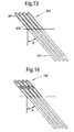
- Figure 13 is a schematic side view of a leaf stack 606 according to a third embodiment of the present invention in which, in each leaf-spacer pair, the spacer 603 folded over the root section 602 to fasten it thereto. The spacing between the leaf sections 601 in the stack is therefore double the spacer thickness.
- Figure 14 is a schematic side view of a leaf stack 706 according to a fourth embodiment of the present invention which, in each leaf-spacer pair, combines a folded over spacer with a push lock fastening arrangement for additional security.
- a further option is to use adhesive to fasten the root section and spacer of each leaf-spacer together.
Landscapes
- Engineering & Computer Science (AREA)
- General Engineering & Computer Science (AREA)
- Mechanical Engineering (AREA)
- Turbine Rotor Nozzle Sealing (AREA)
- Sealing Using Fluids, Sealing Without Contact, And Removal Of Oil (AREA)
- Sealing Devices (AREA)
Abstract
(a) providing a leaf section (301, 501, 601) which maintains, in the leaf seal, wiping contact with one of the components, and a root section (302, 502, 602) from which the leaf section extends and which, in the leaf seal, is fixed relative to the other component, the leaf section and the root section being formed from a first sheet of material of substantially uniform thickness;
(b) providing a spacer (303, 503, 603) formed from a second sheet of material, the spacer being physically separate from the leaf section and the root section; and
(c) fastening the spacer to the root section to form a leaf-spacer pair in which the spacer overlays the root section and remains fixed relative thereto on handling of the leaf-spacer pair.
Description
- The present invention relates to a process for forming a leaf-spacer pair for use in a leaf seal.
- With reference to
Figure 1 , a ducted fan gas turbine engine generally indicated at 10 has a principal and rotational axis X-X. The engine comprises, in axial flow series, anair intake 11, apropulsive fan 12, anintermediate pressure compressor 13, a high-pressure compressor 14,combustion equipment 15, a high-pressure turbine 16, andintermediate pressure turbine 17, a low-pressure turbine 18 and a coreengine exhaust nozzle 19. Anacelle 21 generally surrounds theengine 10 and defines theintake 11, abypass duct 22 and abypass exhaust nozzle 23. - The
gas turbine engine 10 works in a conventional manner so that air entering theintake 11 is accelerated by thefan 12 to produce two air flows: a first air flow A into theintermediate pressure compressor 13 and a second air flow B which passes through thebypass duct 22 to provide propulsive thrust. Theintermediate pressure compressor 13 compresses the air flow A directed into it before delivering that air to thehigh pressure compressor 14 where further compression takes place. - The compressed air exhausted from the high-
pressure compressor 14 is directed into thecombustion equipment 15 where it is mixed with fuel and the mixture combusted. The resultant hot combustion products then expand through, and thereby drive the high, intermediate and low-pressure turbines nozzle 19 to provide additional propulsive thrust. The high, intermediate and low-pressure turbines respectively drive the high andintermediate pressure compressors fan 12 by suitable interconnecting shafts. - Leaf seals are formed from sections of leaf material appropriately presented in order to create a seal surface from juxtaposed leaf edges of respective leaves in an assembly. Typically the leaves are arranged circumferentially about a rotating shaft in order to present the leaf edges and therefore the seal surface towards that shaft in order to provide a seal barrier. Typically, spacer members are provided between each leaf in order to correctly arrange the seal elements for presentation of the leaf edges and therefore the seal surface. These spacers may be independent components or integrally formed with each leaf. The leaf edges and so the seal surface effectively floats upwards and downwards relative to a rotating surface.
- In a gas turbine engine, leaf seals may be used to form a seal between a static component and a rotating component, between two relatively rotating components, or even between two static components in order to maintain a relatively high pressure on one side of the seal and relatively low pressure on the other.
Figure 2 , which shows schematically, for example, a cut-away perspective view of a portion of aleaf seal assembly 31 comprisesseal elements 32 extending fromspacer elements 33 secured in a housing comprising abacking ring 34 withside plates 35. Theseal leaf elements 32present leaf edges 36 towards asurface 37 of a rotating component generally rotating in the direction depicted byarrowhead 38. Theleaves 32, and in particular theleaf edges 36 of theleaves 32 act against thesurface 37 in order to create a seal across theassembly 31. Eachleaf section 32 is generally compliant in order to adjust with rotation of thesurface 11 to ensure that a good sealing effect is created. Thespacers 33 are generally required in order to ensure that flexibility is available to appropriately present theleaf seal elements 32 towards thesurface 37 which, as illustrated, is generally with an inclined angle between them. - Assembly of leaf seals is relatively complex in terms of the number of leaves in the assembly and the importance of correctly aligning and spacing leaves in order to achieve best effect. Formation of leaf seals using a pleated band or strip has been proposed and is described in
WO 015933802 -
EP A 1878955 proposes a method of forming leaf seals comprising etching leaves in a strip, each leaf being etched at a tilt angle to create a step when each leaf is concertina folded against its adjacent neighbour, and folding the strip whereby the leaves are juxtaposed to present a seal surface formed by each leaf edge of each leaf.EP A 1878955 also proposes a method of forming leaf seals comprising etching leaves in a strip, each leaf having a spacer section, and spacers for the leaves being defined by removal of at least part of the remainder of at least some of the leaves. - Thus
Figure 3 shows schematically astrip 50 appropriately photochemically machined in order to create respectiveleaf seal sections 51. Eachleaf seal section 51 comprises aseal element leaf 52 and aroot section 53. Due to the tilt angle L, which is exaggerated for convenient demonstration, there are waste areas in relation tosides 54 andtop 55 which are removed as required. Theroot sections 53 are of thicker section than the operationalleaf seal elements 52 and this is achieved in thestrip 50 through appropriate machining such as photo-chemical machining of theleaf seal elements 52. Between each leaf section 51 afold section 56 is provided to enable a zigzag fold to be performed. Thefold sections 56 can also be thinned to reduce stresses on bending. -
Figure 4 illustrates schematically folding of the leaf sections formed by provision of the foldedsections 56 and the removal of thewaste areas strip 50 depicted inFigure 3 . Thus, as can be seen with thewaste areas root sections 53 are still attached at thefold lines 56 in a staggered configuration. As thefolding section 56 is of a thinner section, a zigzag fold can be provided about thesesections 56 in order to move through the stage depicted inFigure 4(a) to a compressed stack ortuft 60 with juxtaposedroot sections 53 presenting theseal elements 52 at an appropriate lay angle as depicted inFigure 4(b) . Essentially, thestack 60 leans such thatbottom leaf edges 61 are appropriately presented in use relative to a seal surface. - Typically a
hole 62 is provided in eachroot section 53 in order to create a plenum chamber by the juxtaposedroot sections 53 in order to achieve the desired pressure distribution about a seal assembly in use. - As shown in Figures 5 and
6 , it is possible to create astrip 80 in whichleaf elements 81 are again defined betweenfold sections 86, butalternate leaf sections leaf section 81a a root section 83a is provided along with aleaf seal element 82, whilst inadjacent leaf section 81 b the whole of the strip (i.e. thearea 85 as well as area 87) other than aspacer 83b betweenroot sections 83a to whichseal elements 82 are attached. This allows larger inter-leaf gaps to be formed. - A zigzag fold is then performed about
fold edges 86 in order to create acompressed stack 90 which has alternatingroot section 83a andspacers 83b juxtaposed to each other. Again, a pressure equalisation plenum chamber is created byholes 92 in eachroot section 83a andspacer 83b which extends annularly about the seal assembly to achieve sealing efficiency. - Leaf-spacer folded pairs may also be provided. A multitude of such pairs can be assembled into a leaf seal assembly.
- As depicted in
Figure 7(a) a double side arm arrangement has aroot section 103a with ahole 106 to provide a plenum chamber for pressure distribution in the eventual seal assembly. Again foldedsections 101 are provided such that there is a step between thespacer 103a to which a seal element 102 is secured and aspacer 103b. In the double arm arrangement depicted inFigure 7(a) there is anarm 100 in theroot section 103a either side of the element 102. Thestepped alignment 104 is again determined by the tilt angle in the strip from which the leaf-spacer folded pair is formed. - As depicted in
Figure 7(b) a single arm leaf-spacer folded pair is depicted. Thus, again aroot section 203a is provided to which aseal element 202 is secured with anaperture 206 in order to form a plenum chamber for pressure distribution in use. There is a step between theroot section 203a and aspacer 203b. Again, there is afold section 201 in between theroot section 203a and thespacer 203b in order to form the leaf-spacer folded pair for assembly into a leaf seal assembly as described later. - Both the arrangements of leaf-spacer folded pairs depicted in
Figure 7 can be appropriately photochemically machined from a sheet, and both may incorporate reinforcing 107, 207 to facilitate assembly strengths. - The leaf stacks and leaf-spacer folded pairs described above are fitted into an assembly jig and joined together e.g. by a welding or brazing processes, as described in
EP A 1878955 , to form complete leaf seal assemblies. After joining, the folding sections are generally machined away. For example,Figure 8 illustrates an exaggerated fold between two leaf sections. Thus,leaf section 41 a is forced into abutment and brazed or welded or otherwise secured in position againstleaf section 41 b. Thefolding section 45 is thinned and as depicted rounded to reduce stressing. The section to the left ofbroken line 40 can be machined away after brazing theleaf sections - An aim of the present invention is to provide performance improvements in leaf seals.
- Accordingly a first aspect of the present invention provides a process for forming a leaf-spacer pair for use in a leaf seal which effects a seal between two components, wherein the process includes the steps of:
- (a) providing a leaf section which maintains, in the leaf seal, wiping contact with one of the components, and a root section from which the leaf section extends and which, in the leaf seal, is fixed relative to the other component, the leaf section and the root section being formed from a first sheet of material of substantially uniform thickness;
- (b) providing a spacer formed from a second sheet of material, the spacer being physically separate from the leaf section and the root section; and
- (c) fastening the spacer to the root section to form a leaf-spacer pair in which the spacer overlays the root section and remains fixed relative thereto on handling of the leaf-spacer pair. The leaf-spacer pair thus-formed is a separate item that is manoeuvrable and useable independently of any other leaf-spacer pairs. By "physically separate" we mean that the spacer provided at step (b), until fastened to the root section at step (c), has no direct or indirect connection to the leaf section and the root section.
- And a second aspect of the present invention provides a process for forming a stack of leaves for use in a leaf seal, the process including:
- repeatedly performing the process of the first aspect to form a plurality of leaf-spacer pairs; and
- combining the leaf-spacer pairs into a stack in which the leaf sections are arranged face-to-face and the spacers interpose between the root sections to space the leaf sections a controlled distance apart.
- A third aspect of the present invention provides a leaf-spacer pair for use in a leaf seal, the leaf-spacer pair being formed by the process of the first aspect. Thus, the third aspect provides a leaf-spacer pair for use in a leaf seal which effects a seal between two components, the leaf-spacer pair having a leaf section which, in the leaf seal, maintains wiping contact with one of the components, and a root section which, in the leaf seal, is fixed relative to the other component and from which the leaf section extends, the leaf-spacer pair further having a spacer, wherein the leaf section and the root section are formed from a first sheet of material of substantially uniform thickness, the spacer is formed from a second sheet of material, and the spacer is fastened to the root section such that the spacer overlays the root section and remains fixed relative thereto on handling of the leaf-spacer pair. The second sheet is typically not the same sheet as the first sheet. In this way, the second sheet can be a different material and/or have a different thickness to the first sheet. However, it is not excluded that the first and second sheets are of the same material and have the same thickness. A fourth aspect of the present invention provides a stack of leaves for use in a leaf seal, the stack being formed by the process of the second aspect. Thus, the fourth aspect provides a stack of leaves for use in a leaf seal, the stack including a plurality of leaf-spacer pairs of the third aspect combined into a stack in which the leaf sections are arranged face-to-face and the spacers interpose between the root sections to space the leaf sections a controlled distance apart. A fifth aspect of the present invention provides a leaf seal including one or more leaf-spacer pairs of the third aspect or one or more stacks of leaves of the fourth aspect.
- The present invention is at least partly based on a realisation that thinned leaf sections can have problems of poor surface finish and premature leaf section failure.
- Advantageously, however, controlled distances between leaf sections can be achieved by providing separate spacers, and allowing leaf sections to retain the original sheet thickness. In particular, a leaf-spacer pair in which the spacer remains fixed relative to the root portion on handling of the pair facilitates formation of leaf stacks from such pairs and increases flexibility in the material choice and thickness of the spacer.
- Optional features of the invention will now be set out. These are applicable singly or in any combination with any aspect of the invention.
- Optionally, after step (a) and before step (c), the root section can be thinned, e.g. by photochemical machining or micromachining, to provide further control of the distance between the leaf sections in a stack. However, generally, such thinning of the root section is not needed.
- In step (c) the spacer may be mechanically fastened to the root section. For example, the mechanical fastening may conveniently include a press-fit fastening arrangement. Additionally or alternatively, the mechanical fastening may include folding the spacer around the root section to fasten it thereto.
- Additionally or alternatively, in step (c) the spacer may be adhesively fastened to the root section.
- In step (a) the first sheet is preferably a rolled sheet and the leaf section retains the as-rolled finish. For example, the first sheet can be a cold-rolled sheet. Advantageously, a cold-rolled finish has been found to improve leaf section performance and reliability.
- The first sheet may be formed from an Ni-based or a Co-based alloy, such as a superalloy. Alternatively, the first sheet may be formed from an Fe-based alloy, such as a stainless steel.
- The second sheet can be formed from the same material as the first sheet. Alternatively, however, the second sheet can be formed from a different material to the first sheet. For example, the material of the second sheet can have a different coefficient of thermal expansion to the material of the first sheet, allowing a leaf seal formed from such leaf-spacer pairs to exploit differential thermal effects in order to e.g. expand or contract the distance between leaf sections, and hence the effectiveness of the seal, in response to temperature.
- The second sheet can be made from a non-metallic material or a plastic.
- The second sheet may be in a wedge shape to facilitate the creation of a circular seal.
- The second sheet may be pre-stamped to create accurately controlled spacer shape (e.g. wedge) and/or thickness.
- The second sheet may incorporate braze alloy to facilitate the brazing of the seal.
- The second sheet may be made of two (or more) sheets which may or may not be similar. If they are dissimilar with different coefficients of thermal expansion then they may facilitate the leaf-spacer pairs to exploit thermal effects in response to temperature.
- Embodiments and further optional feature of the invention will now be described by way of example with reference to the accompanying drawings in which:
-
Figure 1 shows schematically a longitudinal section through a turbofan engine; -
Figure 2 shows schematically a cut-away perspective view of a portion of a leaf seal assembly; -
Figure 3 shows schematically a strip appropriately photochemically machined in order to create respective leaf seal sections; -
Figure 4 illustrates progressive stages (a) and (b) in the folding of the leaf seal sections ofFigure 3 ; - Figure 5 shows schematically another strip appropriately photochemically machined in order to create respective leaf seal sections;
-
Figure 6 illustrates progressive stages (a) and (b) in the folding of the leaf seal sections of Figure 5; -
Figure 7 shows schematically a seal element and spacers for forming leaf-spacer folded pairs with (a) a double side arm arrangement, and (b) a single side arm arrangement; -
Figure 8 illustrates an exaggerated fold between two leaf sections; -
Figure 9 shows schematically progressive stages (a) and (b) in the formation of a leaf-spacer pair according to a first embodiment of the present invention; -
Figure 10 is a schematic side view of a leaf stack formed by stacking leaf-spacer pairs of the first embodiment; -
Figure 11 is a schematic side view of a further leaf stack formed by stacking leaf-spacer pairs of the first embodiment after bending along the join lines between the leaf sections and the root sections to adjust the lay angle; -
Figure 12 is a schematic side view of a leaf stack according to a second embodiment of the present invention; -
Figure 13 is a schematic side view of a leaf stack according to a third embodiment of the present invention; and -
Figure 14 is a schematic side view of a leaf stack according to a fourth embodiment of the present invention. -
Figure 9 shows schematically progressive stages (a) and (b) in the formation of a leaf-spacer pair according to a first embodiment of the present invention.Figure 9(a) shows aleaf section 301 and aroot section 302 from which the leaf section extends, both stamped from a cold-rolled first sheet of material of substantially uniform thickness. Acentral hole 304 is cut out of the root section.Figure 9(a) also shows aseparate spacer 303 from a second sheet of material. Central cuts in the spacer produce a pair oftabs 305. The spacer is approximately the same size as the root section, but may have a different thickness. - In
Figure 9(b) , thespacer 303 is pressed onto theroot section 302 so that thetabs 305 are bent into thecentral hole 304. In this way, a leaf-spacer pair is formed in which the spacer is mechanically fastened to the root section, so that it overlays the root section and remains fixed relative thereto on subsequent handling of the leaf-spacer pair. - Further leaf-spacer pairs can be formed in the same way, and, as shown in
Figure 10 , these can be combined into astack 306 of lay angle θ in whichleaf sections 301 are arranged face-to-face and thespacers 303 interpose between theroot sections 302 to space the leaf sections a controlled distance apart, the leaf-spacer pairs subsequently being brazed or welded together in the stack. The mechanically fastened spacers remain securely fixed to their respective root sections during the stacking procedure. The thickness t1 of the first sheet from which the leaf and root sections are formed defines the thickness of the leaf sections in the stack, and the thickness t2 of the second sheet from which the spacers are formed determines the spacing between the leaf sections. Conveniently, thecentral hole 304 and the opening formed by thebent tabs 305 can combine in the stack to form a pressure equalisation plenum chamber. Further adjustment to the spacing between the leaf sections can be made by bending along the join lines between the leaf sections and the root sections. As shown inFigure 11 , which is a schematic side view of afurther leaf stack 406, this can produce an adjustment, Δθ, in the lay angle θ of the stack. - Thinning by photochemical machining can be associated with premature leaf section failure (e.g. due to surface roughness and hydrogen embrittlement). However, advantageously, by providing mechanically fastened spacers, it is not necessary to thin the leaf sections to vary the spacing between the leaf sections in the stack. Thus the reliability and longevity of the leaf seal can be improved.
- Various modifications can be made to the fastening arrangement between the root section and spacer in the leaf-spacer pair. For example,
Figure 12 is a schematic side view of aleaf stack 506 according to a second embodiment of the present invention in which, in each leaf-spacer pair, thespacer 503 has a single pushlock press tab 505 which is pushed into acentral hole 504 in theroot section 502. Unlike the first embodiment, a pressure equalisation plenum chamber is not formed.Figure 13 is a schematic side view of aleaf stack 606 according to a third embodiment of the present invention in which, in each leaf-spacer pair, thespacer 603 folded over theroot section 602 to fasten it thereto. The spacing between theleaf sections 601 in the stack is therefore double the spacer thickness.Figure 14 is a schematic side view of aleaf stack 706 according to a fourth embodiment of the present invention which, in each leaf-spacer pair, combines a folded over spacer with a push lock fastening arrangement for additional security. A further option is to use adhesive to fasten the root section and spacer of each leaf-spacer together. - While the invention has been described in conjunction with the exemplary embodiments described above, many equivalent modifications and variations will be apparent to those skilled in the art when given this disclosure. Accordingly, the exemplary embodiments of the invention set forth above are considered to be illustrative and not limiting. Various changes to the described embodiments may be made without departing from the spirit and scope of the invention.
- All references referred to above are hereby incorporated by reference.
Claims (15)
- A process for forming a leaf-spacer pair for use in a leaf seal which effects a seal between two components, wherein the process includes the steps of:(a) providing a leaf section (301; 501; 601) which maintains, in the leaf seal, wiping contact with one of the components, and a root section (302; 502; 602) from which the leaf section extends and which, in the leaf seal, is fixed relative to the other component, the leaf section and the root section being formed from a first sheet of material of substantially uniform thickness;(b) providing a spacer (303; 503; 603) formed from a second sheet of material, the spacer being physically separate from the leaf section and the root section; and(c) fastening the spacer to the root section to form a leaf-spacer pair in which the spacer overlays the root section and remains fixed relative thereto on handling of the leaf-spacer pair.
- A process according to claim 1, wherein in step (c) the spacer is mechanically fastened to the root section.
- A process according to claim 2, wherein the mechanical fastening includes a press-fit fastening arrangement (304, 305; 504, 505).
- A process according to claim 2 or 3, wherein the mechanical fastening includes folding the spacer (603) around the root section (602) to fasten it thereto.
- A process according to any one of the previous claims, wherein in step (c) the spacer is adhesively fastened to the root section.
- A process according to any one of the previous claims, wherein in step (a) the first sheet is a rolled sheet and the leaf section retains the as-rolled finish.
- A process according to any one of the previous claims, wherein the first sheet is formed from an Ni-based or a Co-based alloy or an Fe-based alloy.
- A process according to any one of the previous claims, wherein the second sheet is formed from a different material to the first sheet.
- A process according to any one of the previous claims, wherein the second sheet incorporates some braze alloy to facilitate final brazing of the seal.
- A process according to any one of claims 1 to 8, wherein the second sheet is formed from a non-metallic material or plastic.
- A process according to any one of the previous claims, wherein the second sheet is non-planar and is of a wedge shape to facilitate the construction of arcuate segments.
- A process according to any one of the previous claims, wherein the second sheet is formed itself from more than one sheets of different materials.
- A process according to any one of the previous claims, wherein the second sheet is pre-stamped with raised features to accurately control its thickness and/or shape (such as wedge shape to facilitate the construction of arcuate segments).
- A process for forming a stack of leaves for use in a leaf seal, the process including:repeatedly performing the process of any one of the previous claims to form a plurality of leaf-spacer pairs; andcombining the leaf-spacer pairs into a stack (306; 406; 506; 606; 706) in which the leaf sections are arranged face-to-face and the spacers interpose between the root sections to space the leaf sections a controlled distance apart.
- A leaf-spacer pair for use in a leaf seal, the leaf-spacer pair being formed by the process of any one of claims 1 to 13.
Applications Claiming Priority (1)
| Application Number | Priority Date | Filing Date | Title |
|---|---|---|---|
| GBGB1113590.2A GB201113590D0 (en) | 2011-08-08 | 2011-08-08 | Leaf seal |
Publications (2)
| Publication Number | Publication Date |
|---|---|
| EP2559920A1 true EP2559920A1 (en) | 2013-02-20 |
| EP2559920B1 EP2559920B1 (en) | 2015-05-13 |
Family
ID=44735548
Family Applications (1)
| Application Number | Title | Priority Date | Filing Date |
|---|---|---|---|
| EP20120178790 Not-in-force EP2559920B1 (en) | 2011-08-08 | 2012-08-01 | Leaf seal |
Country Status (4)
| Country | Link |
|---|---|
| US (1) | US8844131B2 (en) |
| EP (1) | EP2559920B1 (en) |
| JP (1) | JP6118047B2 (en) |
| GB (1) | GB201113590D0 (en) |
Families Citing this family (1)
| Publication number | Priority date | Publication date | Assignee | Title |
|---|---|---|---|---|
| US12258866B2 (en) * | 2023-05-29 | 2025-03-25 | Pratt & Whitney Canada Corp. | Seal assembly and method of manufacturing |
Citations (4)
| Publication number | Priority date | Publication date | Assignee | Title |
|---|---|---|---|---|
| WO2001059338A1 (en) | 2000-02-12 | 2001-08-16 | Alstom (Switzerland) Ltd | Rotor seal comprising a pleated band |
| EP1878955A1 (en) | 2006-07-14 | 2008-01-16 | Rolls-Royce plc | Leaf seals |
| EP2123951A1 (en) * | 2008-03-10 | 2009-11-25 | Eagle Industry Co., Ltd. | Leaf seal apparatus |
| EP2206938A2 (en) * | 2009-01-12 | 2010-07-14 | General Electric Company | Method of manufacturing of a compliant plate seal assembly |
Family Cites Families (12)
| Publication number | Priority date | Publication date | Assignee | Title |
|---|---|---|---|---|
| JP4081710B2 (en) * | 2002-04-02 | 2008-04-30 | イーグル・エンジニアリング・エアロスペース株式会社 | Plate brush seal device |
| JP3993536B2 (en) * | 2003-06-20 | 2007-10-17 | 三菱重工業株式会社 | Manufacturing method of shaft seal, shaft seal, shaft seal member, and rotary machine using shaft seal |
| DE102004016173A1 (en) * | 2004-03-30 | 2005-10-20 | Alstom Technology Ltd Baden | Lamella seal, in particular for a gas turbine, and method for its production |
| DE102004020378A1 (en) * | 2004-04-23 | 2005-11-10 | Alstom Technology Ltd | Lamella seal, in particular for a gas turbine, and method for its production |
| GB2413602B (en) * | 2004-04-26 | 2008-02-13 | Alstom Technology Ltd | Process for producing leaves for a leaf seal |
| DE102004059858A1 (en) * | 2004-12-11 | 2006-06-29 | Alstom Technology Ltd | Lamella seal, in particular for a gas turbine |
| US20080107525A1 (en) * | 2006-11-02 | 2008-05-08 | General Electric Company | Shaft seal formed of tapered compliant plate members |
| US7735833B2 (en) * | 2006-11-14 | 2010-06-15 | The University Of Akron | Double padded finger seal |
| US20100143102A1 (en) * | 2008-02-18 | 2010-06-10 | General Electric Company | Compliant plate seal with self-correcting behavior |
| EP2105640B1 (en) * | 2008-03-28 | 2011-04-27 | Alstom Technology Ltd | Leaf seal for turbomachine |
| US8028996B2 (en) * | 2008-04-04 | 2011-10-04 | General Electric Company | System and method for adjusting stiffness of a brush sealing system |
| US8250756B2 (en) | 2009-02-20 | 2012-08-28 | General Electric Company | Method of manufacture of compliant plate seals |
-
2011
- 2011-08-08 GB GBGB1113590.2A patent/GB201113590D0/en not_active Ceased
-
2012
- 2012-08-01 US US13/564,278 patent/US8844131B2/en not_active Expired - Fee Related
- 2012-08-01 EP EP20120178790 patent/EP2559920B1/en not_active Not-in-force
- 2012-08-08 JP JP2012175799A patent/JP6118047B2/en not_active Expired - Fee Related
Patent Citations (4)
| Publication number | Priority date | Publication date | Assignee | Title |
|---|---|---|---|---|
| WO2001059338A1 (en) | 2000-02-12 | 2001-08-16 | Alstom (Switzerland) Ltd | Rotor seal comprising a pleated band |
| EP1878955A1 (en) | 2006-07-14 | 2008-01-16 | Rolls-Royce plc | Leaf seals |
| EP2123951A1 (en) * | 2008-03-10 | 2009-11-25 | Eagle Industry Co., Ltd. | Leaf seal apparatus |
| EP2206938A2 (en) * | 2009-01-12 | 2010-07-14 | General Electric Company | Method of manufacturing of a compliant plate seal assembly |
Also Published As
| Publication number | Publication date |
|---|---|
| JP6118047B2 (en) | 2017-04-19 |
| GB201113590D0 (en) | 2011-09-21 |
| JP2013040681A (en) | 2013-02-28 |
| EP2559920B1 (en) | 2015-05-13 |
| US8844131B2 (en) | 2014-09-30 |
| US20130038025A1 (en) | 2013-02-14 |
Similar Documents
| Publication | Publication Date | Title |
|---|---|---|
| US11073021B2 (en) | Mistuned airfoil assemblies | |
| US11168574B2 (en) | Segmented non-contact seal assembly for rotational equipment | |
| US8257028B2 (en) | Turbine nozzle segment | |
| EP2586978B1 (en) | Turbine of a turbomachine | |
| EP1609952B1 (en) | Turbine vane collar seal | |
| US9033657B2 (en) | Gas turbine engine including lift-off finger seals, lift-off finger seals, and method for the manufacture thereof | |
| US10655489B2 (en) | Systems and methods for assembling flow path components | |
| US7334800B2 (en) | Seal for a gas turbine engine having improved flexibility | |
| CN101144542A (en) | Shaft seal using shingle-type compliant-plate members | |
| US9297259B2 (en) | Compressor blade | |
| EP3252273B1 (en) | System and method for sealing rotor blades with front-loaded seal | |
| EP2599965A2 (en) | Shim seal assembly and assembly methods for stationary components of rotary machines | |
| EP2559920B1 (en) | Leaf seal | |
| JP2017061926A (en) | Ceramic matrix composite ring shroud retention method and finger seal with stepped shroud interface | |
| US9273782B2 (en) | Leaf seal | |
| EP2578910B1 (en) | Strip seals | |
| EP2559921B1 (en) | Leaf Seal | |
| EP2309099B1 (en) | Transition duct | |
| EP4227629A1 (en) | Conformal heat exchanger | |
| US20160245089A1 (en) | Bladed disc | |
| EP3181959A1 (en) | Hula seal | |
| GB2491580A (en) | A method of manufacturing a sheet metal annular combustion chamber | |
| US12078069B2 (en) | Rotor with feather seals | |
| GB2502309A (en) | A honeycomb seal a method of manufacturing a honeycomb seal |
Legal Events
| Date | Code | Title | Description |
|---|---|---|---|
| PUAI | Public reference made under article 153(3) epc to a published international application that has entered the european phase |
Free format text: ORIGINAL CODE: 0009012 |
|
| AK | Designated contracting states |
Kind code of ref document: A1 Designated state(s): AL AT BE BG CH CY CZ DE DK EE ES FI FR GB GR HR HU IE IS IT LI LT LU LV MC MK MT NL NO PL PT RO RS SE SI SK SM TR |
|
| AX | Request for extension of the european patent |
Extension state: BA ME |
|
| 17P | Request for examination filed |
Effective date: 20130816 |
|
| RBV | Designated contracting states (corrected) |
Designated state(s): AL AT BE BG CH CY CZ DE DK EE ES FI FR GB GR HR HU IE IS IT LI LT LU LV MC MK MT NL NO PL PT RO RS SE SI SK SM TR |
|
| GRAP | Despatch of communication of intention to grant a patent |
Free format text: ORIGINAL CODE: EPIDOSNIGR1 |
|
| RIC1 | Information provided on ipc code assigned before grant |
Ipc: F16J 15/32 20060101AFI20150127BHEP |
|
| INTG | Intention to grant announced |
Effective date: 20150219 |
|
| GRAS | Grant fee paid |
Free format text: ORIGINAL CODE: EPIDOSNIGR3 |
|
| GRAA | (expected) grant |
Free format text: ORIGINAL CODE: 0009210 |
|
| AK | Designated contracting states |
Kind code of ref document: B1 Designated state(s): AL AT BE BG CH CY CZ DE DK EE ES FI FR GB GR HR HU IE IS IT LI LT LU LV MC MK MT NL NO PL PT RO RS SE SI SK SM TR |
|
| REG | Reference to a national code |
Ref country code: GB Ref legal event code: FG4D |
|
| REG | Reference to a national code |
Ref country code: CH Ref legal event code: EP |
|
| REG | Reference to a national code |
Ref country code: IE Ref legal event code: FG4D |
|
| REG | Reference to a national code |
Ref country code: AT Ref legal event code: REF Ref document number: 726978 Country of ref document: AT Kind code of ref document: T Effective date: 20150615 |
|
| REG | Reference to a national code |
Ref country code: DE Ref legal event code: R096 Ref document number: 602012007266 Country of ref document: DE Effective date: 20150625 |
|
| RAP2 | Party data changed (patent owner data changed or rights of a patent transferred) |
Owner name: ROLLS-ROYCE PLC |
|
| REG | Reference to a national code |
Ref country code: AT Ref legal event code: MK05 Ref document number: 726978 Country of ref document: AT Kind code of ref document: T Effective date: 20150513 |
|
| REG | Reference to a national code |
Ref country code: NL Ref legal event code: MP Effective date: 20150513 |
|
| REG | Reference to a national code |
Ref country code: LT Ref legal event code: MG4D |
|
| PG25 | Lapsed in a contracting state [announced via postgrant information from national office to epo] |
Ref country code: LT Free format text: LAPSE BECAUSE OF FAILURE TO SUBMIT A TRANSLATION OF THE DESCRIPTION OR TO PAY THE FEE WITHIN THE PRESCRIBED TIME-LIMIT Effective date: 20150513 Ref country code: NO Free format text: LAPSE BECAUSE OF FAILURE TO SUBMIT A TRANSLATION OF THE DESCRIPTION OR TO PAY THE FEE WITHIN THE PRESCRIBED TIME-LIMIT Effective date: 20150813 Ref country code: HR Free format text: LAPSE BECAUSE OF FAILURE TO SUBMIT A TRANSLATION OF THE DESCRIPTION OR TO PAY THE FEE WITHIN THE PRESCRIBED TIME-LIMIT Effective date: 20150513 Ref country code: ES Free format text: LAPSE BECAUSE OF FAILURE TO SUBMIT A TRANSLATION OF THE DESCRIPTION OR TO PAY THE FEE WITHIN THE PRESCRIBED TIME-LIMIT Effective date: 20150513 Ref country code: PT Free format text: LAPSE BECAUSE OF FAILURE TO SUBMIT A TRANSLATION OF THE DESCRIPTION OR TO PAY THE FEE WITHIN THE PRESCRIBED TIME-LIMIT Effective date: 20150914 Ref country code: FI Free format text: LAPSE BECAUSE OF FAILURE TO SUBMIT A TRANSLATION OF THE DESCRIPTION OR TO PAY THE FEE WITHIN THE PRESCRIBED TIME-LIMIT Effective date: 20150513 |
|
| PG25 | Lapsed in a contracting state [announced via postgrant information from national office to epo] |
Ref country code: AT Free format text: LAPSE BECAUSE OF FAILURE TO SUBMIT A TRANSLATION OF THE DESCRIPTION OR TO PAY THE FEE WITHIN THE PRESCRIBED TIME-LIMIT Effective date: 20150513 Ref country code: BG Free format text: LAPSE BECAUSE OF FAILURE TO SUBMIT A TRANSLATION OF THE DESCRIPTION OR TO PAY THE FEE WITHIN THE PRESCRIBED TIME-LIMIT Effective date: 20150813 Ref country code: LV Free format text: LAPSE BECAUSE OF FAILURE TO SUBMIT A TRANSLATION OF THE DESCRIPTION OR TO PAY THE FEE WITHIN THE PRESCRIBED TIME-LIMIT Effective date: 20150513 Ref country code: IS Free format text: LAPSE BECAUSE OF FAILURE TO SUBMIT A TRANSLATION OF THE DESCRIPTION OR TO PAY THE FEE WITHIN THE PRESCRIBED TIME-LIMIT Effective date: 20150913 Ref country code: RS Free format text: LAPSE BECAUSE OF FAILURE TO SUBMIT A TRANSLATION OF THE DESCRIPTION OR TO PAY THE FEE WITHIN THE PRESCRIBED TIME-LIMIT Effective date: 20150513 Ref country code: GR Free format text: LAPSE BECAUSE OF FAILURE TO SUBMIT A TRANSLATION OF THE DESCRIPTION OR TO PAY THE FEE WITHIN THE PRESCRIBED TIME-LIMIT Effective date: 20150814 |
|
| PG25 | Lapsed in a contracting state [announced via postgrant information from national office to epo] |
Ref country code: EE Free format text: LAPSE BECAUSE OF FAILURE TO SUBMIT A TRANSLATION OF THE DESCRIPTION OR TO PAY THE FEE WITHIN THE PRESCRIBED TIME-LIMIT Effective date: 20150513 Ref country code: DK Free format text: LAPSE BECAUSE OF FAILURE TO SUBMIT A TRANSLATION OF THE DESCRIPTION OR TO PAY THE FEE WITHIN THE PRESCRIBED TIME-LIMIT Effective date: 20150513 |
|
| REG | Reference to a national code |
Ref country code: DE Ref legal event code: R097 Ref document number: 602012007266 Country of ref document: DE |
|
| PG25 | Lapsed in a contracting state [announced via postgrant information from national office to epo] |
Ref country code: CZ Free format text: LAPSE BECAUSE OF FAILURE TO SUBMIT A TRANSLATION OF THE DESCRIPTION OR TO PAY THE FEE WITHIN THE PRESCRIBED TIME-LIMIT Effective date: 20150513 Ref country code: RO Free format text: LAPSE BECAUSE OF NON-PAYMENT OF DUE FEES Effective date: 20150513 Ref country code: SK Free format text: LAPSE BECAUSE OF FAILURE TO SUBMIT A TRANSLATION OF THE DESCRIPTION OR TO PAY THE FEE WITHIN THE PRESCRIBED TIME-LIMIT Effective date: 20150513 Ref country code: PL Free format text: LAPSE BECAUSE OF FAILURE TO SUBMIT A TRANSLATION OF THE DESCRIPTION OR TO PAY THE FEE WITHIN THE PRESCRIBED TIME-LIMIT Effective date: 20150513 |
|
| PLBE | No opposition filed within time limit |
Free format text: ORIGINAL CODE: 0009261 |
|
| STAA | Information on the status of an ep patent application or granted ep patent |
Free format text: STATUS: NO OPPOSITION FILED WITHIN TIME LIMIT |
|
| PG25 | Lapsed in a contracting state [announced via postgrant information from national office to epo] |
Ref country code: MC Free format text: LAPSE BECAUSE OF FAILURE TO SUBMIT A TRANSLATION OF THE DESCRIPTION OR TO PAY THE FEE WITHIN THE PRESCRIBED TIME-LIMIT Effective date: 20150513 Ref country code: LU Free format text: LAPSE BECAUSE OF FAILURE TO SUBMIT A TRANSLATION OF THE DESCRIPTION OR TO PAY THE FEE WITHIN THE PRESCRIBED TIME-LIMIT Effective date: 20150801 |
|
| REG | Reference to a national code |
Ref country code: CH Ref legal event code: PL |
|
| 26N | No opposition filed |
Effective date: 20160216 |
|
| PG25 | Lapsed in a contracting state [announced via postgrant information from national office to epo] |
Ref country code: LI Free format text: LAPSE BECAUSE OF NON-PAYMENT OF DUE FEES Effective date: 20150831 Ref country code: CH Free format text: LAPSE BECAUSE OF NON-PAYMENT OF DUE FEES Effective date: 20150831 Ref country code: IT Free format text: LAPSE BECAUSE OF FAILURE TO SUBMIT A TRANSLATION OF THE DESCRIPTION OR TO PAY THE FEE WITHIN THE PRESCRIBED TIME-LIMIT Effective date: 20150513 |
|
| REG | Reference to a national code |
Ref country code: DE Ref legal event code: R082 Ref document number: 602012007266 Country of ref document: DE Representative=s name: HERNANDEZ, YORCK, DIPL.-ING., DE |
|
| PG25 | Lapsed in a contracting state [announced via postgrant information from national office to epo] |
Ref country code: SI Free format text: LAPSE BECAUSE OF FAILURE TO SUBMIT A TRANSLATION OF THE DESCRIPTION OR TO PAY THE FEE WITHIN THE PRESCRIBED TIME-LIMIT Effective date: 20150513 |
|
| REG | Reference to a national code |
Ref country code: IE Ref legal event code: MM4A |
|
| PG25 | Lapsed in a contracting state [announced via postgrant information from national office to epo] |
Ref country code: IE Free format text: LAPSE BECAUSE OF NON-PAYMENT OF DUE FEES Effective date: 20150801 |
|
| REG | Reference to a national code |
Ref country code: FR Ref legal event code: PLFP Year of fee payment: 5 |
|
| PG25 | Lapsed in a contracting state [announced via postgrant information from national office to epo] |
Ref country code: BE Free format text: LAPSE BECAUSE OF FAILURE TO SUBMIT A TRANSLATION OF THE DESCRIPTION OR TO PAY THE FEE WITHIN THE PRESCRIBED TIME-LIMIT Effective date: 20150513 |
|
| PG25 | Lapsed in a contracting state [announced via postgrant information from national office to epo] |
Ref country code: MT Free format text: LAPSE BECAUSE OF FAILURE TO SUBMIT A TRANSLATION OF THE DESCRIPTION OR TO PAY THE FEE WITHIN THE PRESCRIBED TIME-LIMIT Effective date: 20150513 |
|
| PG25 | Lapsed in a contracting state [announced via postgrant information from national office to epo] |
Ref country code: HU Free format text: LAPSE BECAUSE OF FAILURE TO SUBMIT A TRANSLATION OF THE DESCRIPTION OR TO PAY THE FEE WITHIN THE PRESCRIBED TIME-LIMIT; INVALID AB INITIO Effective date: 20120801 Ref country code: SM Free format text: LAPSE BECAUSE OF FAILURE TO SUBMIT A TRANSLATION OF THE DESCRIPTION OR TO PAY THE FEE WITHIN THE PRESCRIBED TIME-LIMIT Effective date: 20150513 |
|
| PG25 | Lapsed in a contracting state [announced via postgrant information from national office to epo] |
Ref country code: NL Free format text: LAPSE BECAUSE OF FAILURE TO SUBMIT A TRANSLATION OF THE DESCRIPTION OR TO PAY THE FEE WITHIN THE PRESCRIBED TIME-LIMIT Effective date: 20150513 Ref country code: SE Free format text: LAPSE BECAUSE OF FAILURE TO SUBMIT A TRANSLATION OF THE DESCRIPTION OR TO PAY THE FEE WITHIN THE PRESCRIBED TIME-LIMIT Effective date: 20150513 Ref country code: CY Free format text: LAPSE BECAUSE OF FAILURE TO SUBMIT A TRANSLATION OF THE DESCRIPTION OR TO PAY THE FEE WITHIN THE PRESCRIBED TIME-LIMIT Effective date: 20150513 |
|
| REG | Reference to a national code |
Ref country code: FR Ref legal event code: PLFP Year of fee payment: 6 |
|
| PG25 | Lapsed in a contracting state [announced via postgrant information from national office to epo] |
Ref country code: TR Free format text: LAPSE BECAUSE OF FAILURE TO SUBMIT A TRANSLATION OF THE DESCRIPTION OR TO PAY THE FEE WITHIN THE PRESCRIBED TIME-LIMIT Effective date: 20150513 |
|
| PG25 | Lapsed in a contracting state [announced via postgrant information from national office to epo] |
Ref country code: MK Free format text: LAPSE BECAUSE OF FAILURE TO SUBMIT A TRANSLATION OF THE DESCRIPTION OR TO PAY THE FEE WITHIN THE PRESCRIBED TIME-LIMIT Effective date: 20150513 |
|
| REG | Reference to a national code |
Ref country code: FR Ref legal event code: PLFP Year of fee payment: 7 |
|
| PG25 | Lapsed in a contracting state [announced via postgrant information from national office to epo] |
Ref country code: AL Free format text: LAPSE BECAUSE OF FAILURE TO SUBMIT A TRANSLATION OF THE DESCRIPTION OR TO PAY THE FEE WITHIN THE PRESCRIBED TIME-LIMIT Effective date: 20150513 |
|
| PGFP | Annual fee paid to national office [announced via postgrant information from national office to epo] |
Ref country code: FR Payment date: 20190826 Year of fee payment: 8 Ref country code: DE Payment date: 20190828 Year of fee payment: 8 |
|
| PGFP | Annual fee paid to national office [announced via postgrant information from national office to epo] |
Ref country code: GB Payment date: 20190827 Year of fee payment: 8 |
|
| REG | Reference to a national code |
Ref country code: DE Ref legal event code: R119 Ref document number: 602012007266 Country of ref document: DE |
|
| GBPC | Gb: european patent ceased through non-payment of renewal fee |
Effective date: 20200801 |
|
| PG25 | Lapsed in a contracting state [announced via postgrant information from national office to epo] |
Ref country code: DE Free format text: LAPSE BECAUSE OF NON-PAYMENT OF DUE FEES Effective date: 20210302 Ref country code: FR Free format text: LAPSE BECAUSE OF NON-PAYMENT OF DUE FEES Effective date: 20200831 |
|
| PG25 | Lapsed in a contracting state [announced via postgrant information from national office to epo] |
Ref country code: GB Free format text: LAPSE BECAUSE OF NON-PAYMENT OF DUE FEES Effective date: 20200801 |