EP2559861A2 - Rotatable component, coating and method of coating the rotatable component of an engine - Google Patents
Rotatable component, coating and method of coating the rotatable component of an engine Download PDFInfo
- Publication number
- EP2559861A2 EP2559861A2 EP20120179580 EP12179580A EP2559861A2 EP 2559861 A2 EP2559861 A2 EP 2559861A2 EP 20120179580 EP20120179580 EP 20120179580 EP 12179580 A EP12179580 A EP 12179580A EP 2559861 A2 EP2559861 A2 EP 2559861A2
- Authority
- EP
- European Patent Office
- Prior art keywords
- zone
- abradable
- approximately
- engine component
- millimeters
- Prior art date
- Legal status (The legal status is an assumption and is not a legal conclusion. Google has not performed a legal analysis and makes no representation as to the accuracy of the status listed.)
- Withdrawn
Links
Images




Classifications
-
- F—MECHANICAL ENGINEERING; LIGHTING; HEATING; WEAPONS; BLASTING
- F01—MACHINES OR ENGINES IN GENERAL; ENGINE PLANTS IN GENERAL; STEAM ENGINES
- F01D—NON-POSITIVE DISPLACEMENT MACHINES OR ENGINES, e.g. STEAM TURBINES
- F01D11/00—Preventing or minimising internal leakage of working-fluid, e.g. between stages
- F01D11/08—Preventing or minimising internal leakage of working-fluid, e.g. between stages for sealing space between rotor blade tips and stator
- F01D11/12—Preventing or minimising internal leakage of working-fluid, e.g. between stages for sealing space between rotor blade tips and stator using a rubstrip, e.g. erodible. deformable or resiliently-biased part
- F01D11/122—Preventing or minimising internal leakage of working-fluid, e.g. between stages for sealing space between rotor blade tips and stator using a rubstrip, e.g. erodible. deformable or resiliently-biased part with erodable or abradable material
-
- B—PERFORMING OPERATIONS; TRANSPORTING
- B33—ADDITIVE MANUFACTURING TECHNOLOGY
- B33Y—ADDITIVE MANUFACTURING, i.e. MANUFACTURING OF THREE-DIMENSIONAL [3D] OBJECTS BY ADDITIVE DEPOSITION, ADDITIVE AGGLOMERATION OR ADDITIVE LAYERING, e.g. BY 3D PRINTING, STEREOLITHOGRAPHY OR SELECTIVE LASER SINTERING
- B33Y80/00—Products made by additive manufacturing
-
- Y—GENERAL TAGGING OF NEW TECHNOLOGICAL DEVELOPMENTS; GENERAL TAGGING OF CROSS-SECTIONAL TECHNOLOGIES SPANNING OVER SEVERAL SECTIONS OF THE IPC; TECHNICAL SUBJECTS COVERED BY FORMER USPC CROSS-REFERENCE ART COLLECTIONS [XRACs] AND DIGESTS
- Y10—TECHNICAL SUBJECTS COVERED BY FORMER USPC
- Y10T—TECHNICAL SUBJECTS COVERED BY FORMER US CLASSIFICATION
- Y10T428/00—Stock material or miscellaneous articles
- Y10T428/25—Web or sheet containing structurally defined element or component and including a second component containing structurally defined particles
-
- Y—GENERAL TAGGING OF NEW TECHNOLOGICAL DEVELOPMENTS; GENERAL TAGGING OF CROSS-SECTIONAL TECHNOLOGIES SPANNING OVER SEVERAL SECTIONS OF THE IPC; TECHNICAL SUBJECTS COVERED BY FORMER USPC CROSS-REFERENCE ART COLLECTIONS [XRACs] AND DIGESTS
- Y10—TECHNICAL SUBJECTS COVERED BY FORMER USPC
- Y10T—TECHNICAL SUBJECTS COVERED BY FORMER US CLASSIFICATION
- Y10T428/00—Stock material or miscellaneous articles
- Y10T428/31504—Composite [nonstructural laminate]
Definitions
- the present invention relates generally to turbines, and more specifically to rotatable components, coating and method of coating the rotatable component of an engine in a gas turbine or steam turbine.
- Tip rub of the airfoil tip with the compressor casing causes detrimental effects, such as high loads transferred to the root of the airfoil, high heat transmitted to the airfoil blade material, which results in fatigue debit, and micro-cracking of the airfoil.
- Attempts to reduce efficiency debit from large clearances between the airfoil tip and casing, such as by providing abradable casings of case liners and oversized seals have been somewhat unsuccessful because these methods are subject to limitations such as complex repair procedures necessary to access the abradable case liner.
- a rotatable component, coating and method of coating the rotatable components for engines that do not suffer from the above drawbacks is desirable in the art.
- a rotatable engine component includes a substrate, a transitional zone applied to the substrate, and an abradable zone applied to the transitional zone.
- the abradable zone is consumed upon contact with a static portion of the engine.
- a coating for a rotatable component includes a transitional zone applied to a substrate of the component and an abradable zone applied to the transitional zone.
- the abradable zone includes a plurality of abradable layers including a plurality of fused ultra fine powder particles, wherein the coating withstands rotational force and the abradable zone is consumed upon contact with a static portion of a gas turbine engine.
- a method of coating a rotatable engine component includes providing the rotatable engine component having a substrate, applying a transitional zone to the substrate, and applying an abradable zone to the transitional zone.
- the abradable zone is consumed upon contact with a static portion of the gas turbine engine.
- FIG. 1 is a schematic illustration of a gas turbine engine 100 including a fan assembly 102, a high pressure compressor 104, and a combustor 106.
- Gas turbine engine 100 also includes a high pressure turbine 108 and a low pressure turbine 110.
- Gas turbine engine 100 has an intake side 128 and an exhaust side 130.
- FIG. 1 depicted as a gas turbine engine, it should be understood that the concepts described herein are not limited to use with gas turbines as the teaching may be applies to other types of engines, including steam turbine engines, turbo fan engines, and others.
- the gas turbine engine 100 includes a low pressure compressor 110 and a high pressure compressor 112.
- Each of the compressors incorporates rotating sets of airfoils (e.g., blade 114) and stationary sets of airfoils (e.g., vane 116).
- the stationary set of airfoils 116 are embedded in the static portion 118 (e.g. casing) of the gas turbine engine 100.
- the rotating airfoils 114 are disposed adjacent to the static portion 118 which creates a static flow path or gap 220 (see FIG. 2 ).
- the clearance or gap 220 is shown between the rotating airfoils 114 and static portion 118; however, upon start-up and shut down of the gas turbine engine 100, the tip 226 of the rotating airfoil 114 can come into contact with the static portion 118, called a tip-rub.
- FIG. 3 is an enlarged schematic of the rotating airfoil 114 and static portion 118 of the compressor 104 of the engine 100 shown in FIG. 2 .
- the rotating airfoil 114 includes a tip 226 having a coating 222 applied to the surface 342 of the substrate 344.
- the coating 222 includes a transitional zone 346 applied to the substrate 344 and an abradable zone 348 applied to the transitional zone 346.
- the coating 222 withstands the rotational force that the rotating airfoil 114 is subjected to during operation of the gas turbine engine 100.
- the coating 222 is applied to a new rotating airfoil 114 to reduce the likelihood of damage to the rotating airfoil 114.
- the coating 222 is used to repair and extend the service life of the rotating airfoil 114.
- the abradable zone 348 of the coating 222 is consumed upon contact with the static portion 118 of the gas turbine engine 110, during an event, such as, but not limited to, tip-rub.
- an event such as, but not limited to, tip-rub.
- the coating surface 354 of the airfoil 114 comes in contact with the surface 352 of the static portion 118 or casing of the gas turbine engine 100.
- the contact between the coating surface 354 of the airfoil 114 and the surface 352 of the static portion 118 generally occurs during start-up or shut-down with each revolution of the airfoil 114.
- This high speed contact causes the abradable layer 348 to wear off or discharge from the airfoil 114, instead the of contact force being absorbed by the airfoil 114, which could cause damage to the root, tip, or other portions of the rotating airfoil. 114.
- the substrate 344 of the airfoil 114 is selected from materials, such as, but not limited to, stainless steel alloys, nickel-based alloys, titanium alloys, aluminum alloys, aluminum-lithium alloys, and combinations thereof.
- suitable stainless steel alloys are, but not limited to, 17-4PH, 13-8PH, 15-5PH, M152.
- suitable nickel-based alloys are, but not limited to Inconel 600, Inconel 617, Inconel 625, and Inconel 718.
- suitable titanium alloys are, but not limited to Ti6-4 and Ti6-2-2-2-2.
- the transitional zone 346 as applied to the surface 324 of the substrate 344 includes at least one transitional layer 358 of a fused powder composition 400 (see FIG. 5 ).
- the fused powder composition 401 includes a plurality of powder particles 412 fused, melted or joined together by an energy source to form the transitional layer 358.
- the transitional zone 346 is applied using any suitable technique generally including thermal energy. Examples of thermal energy application methods for applying the transitional zone 346, are, but not limited to, an electro-spark deposition (ESD) process, an electron beam welding process, a laser powder fusion welding process, a direct metal laser sintering process, and combinations thereof.
- ESD electro-spark deposition
- the abradable zone 348 includes at least one layer, but generally includes a plurality of abradable layers 356 including a fused powder composition 400 (see FIG. 5 ).
- the fused powder composition 400 includes a plurality of powder particles 412 fused, melted or joined together by an energy source to form the abradable layer 356.
- the abradable zone 348 is applied using any suitable technique, including, but not limited to, an electro-spark deposition (ESD) process, an electron beam welding process, a laser powder fusion welding process, a direct metal laser sintering process, and combinations thereof. As shown in FIG.
- ESD electro-spark deposition
- the pre-fused powder composition 401 includes a plurality of powder particles 412 and binder particles 416, dispersed amongst the powder particles 412. As the energy source is applied to the nominal unit cells of powder particles 412, the binder particles 416 melt or disperse and the powder particles 412 join together at adjacent surfaces to form the abradable layer 356.
- laser beam may be focused on an approximately 2 millimeters to approximately 10 millimeters, or alternatively 3 milliliters to approximately 8 millimeters, or approximately 4 millimeters to approximately 6 millimeters diameter patch of powder particles 412.
- the thermal energy from laser beam generally penetrates approximately 0.2 millimeters to approximately 2 millimeters, or alternatively 0.3 millimeters to approximately 1.8 millimeters to approximately 0.4 millimeters to approximately 1.7 millimeters into the powder particles 412, thereby simultaneously evolving or volatizing binder particles 416 from the system and fusing adjacent non-binder particles 412 into fused powder particles 414 (see FIG. 5 ).
- the pre-fused powder composition 401 for either the transitional layers 358 or the abradable layers 356 includes a plurality of powder particles 412 and binder particles 416 inter-dispersed amongst the powder particles 412 with a minimal amount of void space 410 therebetween. As shown in FIG. 4 , there is an optimal packing density between the powder particles 412 and the binder particles 416, such that the particle size of the binder particles 416 is approximately the square root of the powder particles 412. In another embodiment, the powder particles 412 and binder particles 416 can be ordered or randomly dispersed.
- the plurality of powder particles 412 and binder particles 416 are deposited on the surface 342 of the substrate 344, as a single layer or a plurality of layers using any suitable technique, such as, for example, but not limited to powder deposition.
- the binder particles 416 melt or disintegrate and the powder particles 412 are joined together at a fusion zone 418 to form a plurality of fused powder particles 414 (see FIG. 5 ) that form a transitional layer 358 or an abradable layer 356.
- the binder particles 416 are selected from a material capable of melting, disintegrating or vaporing at approximately 150°C or greater.
- the binder particle 416 material is, but not limited to, a volatile wax, which vaporizes at approximately 150 °C to approximately 300°C.
- the ratio of volume of the binder particles 416 to the powder particles 412 is approximately 0.1 percent to approximately 50 percent binder particles 416, or alternatively 3 percent to approximately 35 percent binder particles 416, or alternatively 5 percent to approximately 25 percent binder particle 416.
- the binder particles 416 have a particle size of approximately 0.010 millimeters to approximately 0.150 millimeters, or alternatively approximately 0.040 millimeters to approximately 0.100 millimeters, or alternatively approximately 0.050 millimeters to approximately 0.090 millimeters.
- the plurality of powder particles 412 of the pre-fused powder composition 401 are selected from a material that is substantially the same as material that is used for the substrate 344.
- the materials of the substrate 344 and the transitional zone 346 are substantially the same, but the density of the transitional zone 346, because of the method of application, is less than that of the substrate 344.
- Using substantially same material for the substrate 344 and the transitional zone 346 promotes adhesion of the transitional zone 346 to the substrate 344 during high-speed rotation.
- the transitional zone 346 functions as an adhesive region effectively joining or adhering the abradable zone 348 to the substrate 344.
- the thickness of the transitional zone 346 is approximately less than 10% of the overall rotating airfoil 114 (blade) length.
- the powder particles 412 of the transitional zone 346 have a particle size of approximately 0.010 millimeters to approximately 0.150 millimeters, or alternatively approximately 0.040 millimeters to approximately 0.100 millimeters, or alternatively approximately 0.050 millimeters to approximately 0.090 millimeters.
- the plurality of powder particles 412 before fusing, have a particle size of approximately 0.020 millimeters to approximately 0.50 millimeters, or alternatively approximately 0.050 millimeters to approximately 0.300 millimeters, or alternatively approximately 0.080 millimeters to approximately 0.150 millimeters.
- the powder particles 412 in the abradable zone are the same size.
- the powder particles 412 for the abradable zone 348 contains approximately 10 percent to approximately 60 percent less of the strengthening elements that make up the substrate 344.
- the material for the abradable zone 348 is a stainless steel having a reduced carbon content compared to that of the substrate 344 material selected from stainless steel.
- the material for the abradable zone 348 contains a proportionally lower amount of alloying elements to achieve a lower overall strength that that of the substrate 344 material.
- the abradable zone 348 has a reduced hardness of approximately 140 Brinell to approximately 380 Brinell or alternatively approximately 150 Brinell to approximately 300 Brinell or alternatively approximately 160 Brinell to approximately 250 Brinell.
- a critical performance aspect of the abradable zone 348 is that the abradable zone does not transmit excess heat into the rotating airfoil 114 or blade and does not transmit excess load into rotating airfoil 114, this accomplished by the abradable zone 348 being sacrificed during a tip-rub or similar contact event between the surface of the rotating airfoil 114 and the static portion 118 or casing of the gas turbine engine 100.
- the abradable zone 348 has a yield strength of approximately 344 Megapascal to approximately 1724 Megapascal or alternatively approximately 360 Megapascal to approximately 1720 Megapascal or alternatively approximately 400 Megapascal to approximately 1700 Megapascal. In an embodiment, the abradable zone 348 has a thickness of approximately 0.06 millimeters to approximately 100 millimeters or alternatively approximately 0.12 millimeters to approximately 15 millimeters or alternatively approximately 0.8 millimeters to approximately 5 millimeters.
- the pre-fused powder composition 401 for either the transitional layers 358 or the abradable layers 356 includes a plurality of powder particles 412 having void areas 410 randomly dispersed throughout.
- the plurality of powder particles 412 are randomly dispersed and vary in particle size.
- the desired density for the transitional layers 358 and abradable layers 356 determines the powder particle 412 size, shape, positioning, packing density, and packing order.
- the powder particles 412 are ordered or optimally dispersed as depicted in FIG. 4 .
- the plurality of powder particles 412 are approximately the same size.
- the plurality of particles 412 become a fused powder composition 400, with a plurality of fused particles 414 joined together at a fusion zone 418 having a number of void areas 410.
- the void areas 410 provided the reduced density to the transitional layers 358 of the transitional zone 346 and abradable layers 356 of the abradable zone 348.
- FIG. 8 is a schematic of another embodiment of a rotating component of the present disclosure.
- the air foil 114 includes a substrate 344, a transitional zone 346 and an abradable zone 348 including a abradable zone coating 350.
- FIG. 9 is a cross-section taken along line 9-9 of FIG. 8 illustrating the various layers of the rotatable component 114.
- the transitional zone 346 includes at least one transitional layer applied to the surface 342 of the substrate 344.
- the transitional zone 346 is applied using any suitable method described above.
- the abradable zone 348 is applied to the transitional zone 346 by any suitable method described above.
- the abradable zone 348 includes a plurality of abradable layers 356.
- the plurality of abradable layers 356 include a plurality of fused powder structures 420.
- the plurality of fused powder structures include a plurality of fused powder particles 414 and void areas 410.
- the geometry of the plurality of fused powder structures 420 includes selectively hollowed spheres (as shown in FIG. 9 ), selectively hollowed pyramids, and other various geometries that allow for the abradable zone 348 to remain fixed to the transitional zone 346 while rotating.
- the three-dimensional geometries of the fused powder structures 420 are created using a 3-D laser sinter process.
- an abradable coating layer 350 is applied to the abradable zone 348.
- the abradable coating layer 350 or skin prevents unnecessary airflow through the void areas 410 of the fused powder structures 420 (see FIG. 8 ).
- the abradable coating layer 350 material is selected from the same material as the abradable zone. In one embodiment, the abradable coating layer is applied using a 3-D laser sintering process, in another embodiment the abradable coating layer is applied using any other suitable coating process.
- the abradable coating layer 350 thickness is approximately 0.06 millimeters to approximately 10 millimeters or alternatively approximately 0.12 millimeters to approximately 8 millimeters or alternatively approximately 0.8 millimeters to approximately 5 millimeters.
- a coating 222 for a rotating airfoil 222 is provided.
- the coating includes a transitional zone 346 applied to a substrate 344 and an abradable zone 348 applied to the transitional zone 346.
- the abradable zone 348 includes a plurality of abradable layers 356 including a plurality of fused powder particles 414 (see FIG.5 ) or a plurality of fused powder structures 420 (see FIG. 9 ).
- the abradable zone 348 includes an abradable coating layer 350. The coating 222 withstands rotational force and the abradable zone 348 is consumed upon contact with a static portion 118 of a gas turbine engine 100.
- a method of coating a rotatable engine component 114 includes providing the rotatable engine component 114 having a substrate 344. Applying a transitional zone 346 to the surface 342 of the substrate 344. Applying an abradable zone 348 to the transitional zone 346, wherein the abradable zone 348 is consumed upon contact with a static portion 118 (e.g. case liner of a gas turbine engine) of the engine 100.
- the transitional zone 346 is applied using thermal energy.
- the transitional zone 346 acts an intermediate or adhesive layer to keep the abradable zone 348 from detaching from the substrate 344 during rotation.
- the abradable zone 348 is applied using a laser densification process, a laser powder fusion welding process, a direct-metal laser sintering process, an electron beam welding process, an electrostatic deposition process, and combinations thereof.
- the surface 342 of the substrate 344 of the rotatable gas turbine component 114 is optionally prepared before applying the transitional zone.
- the optional step of preparation includes removal of any remaining existing abradable layers 356 or transitional layers 358 from the surface 342 of the substrate 344. Examples of processes used for removal are, but not limited to, any method for flattening the surface 342 of the substrate 344, such as, but not limited to, grinding and sanding.
- One advantage of an embodiment of the present disclosure includes an engine having tighter clearance control between the blade tip and casing.
- Another advantage of an embodiment of the present disclosure is high compressor efficiency resulting from the tighter clearances of compressor design.
- Another advantage of an embodiment of the present disclosure is robust compressor operation because the air foil damage is removed when tip rub occurs between the air foil tip and casing.
- Another advantage of an embodiment of the present disclosure is that inspections and blending of airfoils in the field is eliminated.
- Yet another advantage of an embodiment of the present disclosure is the abradable tip allows the blade to withstand high speed contact with the casing without suffering detrimental effects associated with tip rub.
- Another advantage of an embodiment of the present disclosure is the compressor can continue to run without causing danger of crack initiation at the airfoil tip or root after a tip rub event.
Landscapes
- Engineering & Computer Science (AREA)
- Mechanical Engineering (AREA)
- General Engineering & Computer Science (AREA)
- Structures Of Non-Positive Displacement Pumps (AREA)
- Powder Metallurgy (AREA)
Abstract
A rotatable engine component (114), coating (222) and method of coating the rotatable component (114) includes a substrate (344), a transitional zone (346) applied to the substrate (344), and an abradable zone (348) applied to the transitional zone (346). During operation of an engine (100) in a turbine, the abradable zone (348) is consumed upon contact with a static portion (118) of the engine (100) preventing damage to the rotatable component (114).
Description
- The present invention relates generally to turbines, and more specifically to rotatable components, coating and method of coating the rotatable component of an engine in a gas turbine or steam turbine.
- Tip rub of the airfoil tip with the compressor casing causes detrimental effects, such as high loads transferred to the root of the airfoil, high heat transmitted to the airfoil blade material, which results in fatigue debit, and micro-cracking of the airfoil. Attempts to reduce efficiency debit from large clearances between the airfoil tip and casing, such as by providing abradable casings of case liners and oversized seals have been somewhat unsuccessful because these methods are subject to limitations such as complex repair procedures necessary to access the abradable case liner.
- A rotatable component, coating and method of coating the rotatable components for engines that do not suffer from the above drawbacks is desirable in the art.
- According to a first aspect of the present invention, a rotatable engine component is provided. The rotatable engine component includes a substrate, a transitional zone applied to the substrate, and an abradable zone applied to the transitional zone. The abradable zone is consumed upon contact with a static portion of the engine.
- According to another aspect of the present invention, a coating for a rotatable component is provided. The coating for the rotatable component includes a transitional zone applied to a substrate of the component and an abradable zone applied to the transitional zone. The abradable zone includes a plurality of abradable layers including a plurality of fused ultra fine powder particles, wherein the coating withstands rotational force and the abradable zone is consumed upon contact with a static portion of a gas turbine engine.
- According to yet another aspect of the present invention, a method of coating a rotatable engine component is provided. The method of coating the rotatable engine component includes providing the rotatable engine component having a substrate, applying a transitional zone to the substrate, and applying an abradable zone to the transitional zone. The abradable zone is consumed upon contact with a static portion of the gas turbine engine.
- Other features and advantages of the present invention will be apparent from the following more detailed description of the preferred embodiment, taken in conjunction with the accompanying drawings which illustrate, by way of example, the principles of the invention.
- Embodiments of the present invention will now be described, by way of example only, with reference to the accompanying drawings in which:
-
FIG. 1 is schematic illustration of a gas turbine engine of the present disclosure. -
FIG. 2 is an enlarged view of the compressor components of the gas turbine engine shown inFIG. 1 . -
FIG. 3 is an enlarged view of the rotating airfoil and static portion of the compressor components shown inFIG. 2 . -
FIG. 4 is an enlarged schematic of the pre-fused powder system of the rotating airfoil shown inFIG. 3 . -
FIG. 5 is an enlarged schematic of fused powered system the rotating airfoil shown inFIG. 3 . -
FIG. 6 is a schematic of the pre-fused powder system of an alternative embodiment of the present disclosure. -
FIG. 7 is a schematic of the fused powdered system of an alternative embodiment of the present disclosure. -
FIG. 8 is a schematic of a rotating airfoil of the present disclosure. -
FIG. 9 is a section view taken along line 9-9 of rotating airfoil ofFIG. 8 of the present disclosure. - Wherever possible, the same reference numbers will be used throughout the drawings to represent the same parts.
-
FIG. 1 is a schematic illustration of agas turbine engine 100 including afan assembly 102, ahigh pressure compressor 104, and acombustor 106.Gas turbine engine 100 also includes ahigh pressure turbine 108 and alow pressure turbine 110.Gas turbine engine 100 has an intake side 128 and an exhaust side 130. Although depicted as a gas turbine engine, it should be understood that the concepts described herein are not limited to use with gas turbines as the teaching may be applies to other types of engines, including steam turbine engines, turbo fan engines, and others. - In
FIG. 1 , thegas turbine engine 100 includes alow pressure compressor 110 and ahigh pressure compressor 112. Each of the compressors incorporates rotating sets of airfoils (e.g., blade 114) and stationary sets of airfoils (e.g., vane 116). The stationary set ofairfoils 116 are embedded in the static portion 118 (e.g. casing) of thegas turbine engine 100. Therotating airfoils 114 are disposed adjacent to thestatic portion 118 which creates a static flow path or gap 220 (seeFIG. 2 ). InFIG. 2 , the clearance orgap 220 is shown between therotating airfoils 114 andstatic portion 118; however, upon start-up and shut down of thegas turbine engine 100, thetip 226 of therotating airfoil 114 can come into contact with thestatic portion 118, called a tip-rub. -
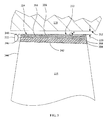
FIG. 3 is an enlarged schematic of the rotatingairfoil 114 andstatic portion 118 of thecompressor 104 of theengine 100 shown inFIG. 2 . The rotatingairfoil 114 includes atip 226 having acoating 222 applied to thesurface 342 of thesubstrate 344. Thecoating 222 includes atransitional zone 346 applied to thesubstrate 344 and anabradable zone 348 applied to thetransitional zone 346. Thecoating 222 withstands the rotational force that the rotatingairfoil 114 is subjected to during operation of thegas turbine engine 100. In one embodiment, thecoating 222 is applied to a new rotatingairfoil 114 to reduce the likelihood of damage to the rotatingairfoil 114. In another embodiment, thecoating 222 is used to repair and extend the service life of the rotatingairfoil 114. Theabradable zone 348 of thecoating 222 is consumed upon contact with thestatic portion 118 of thegas turbine engine 110, during an event, such as, but not limited to, tip-rub. During a contact event, such as tip-rub, thecoating surface 354 of theairfoil 114 comes in contact with thesurface 352 of thestatic portion 118 or casing of thegas turbine engine 100. The contact between thecoating surface 354 of theairfoil 114 and thesurface 352 of thestatic portion 118 generally occurs during start-up or shut-down with each revolution of theairfoil 114. This high speed contact causes theabradable layer 348 to wear off or discharge from theairfoil 114, instead the of contact force being absorbed by theairfoil 114, which could cause damage to the root, tip, or other portions of the rotating airfoil. 114. - The
substrate 344 of theairfoil 114 is selected from materials, such as, but not limited to, stainless steel alloys, nickel-based alloys, titanium alloys, aluminum alloys, aluminum-lithium alloys, and combinations thereof. Examples of suitable stainless steel alloys are, but not limited to, 17-4PH, 13-8PH, 15-5PH, M152. Examples of suitable nickel-based alloys are, but not limited to Inconel 600, Inconel 617, Inconel 625, and Inconel 718. Examples of suitable titanium alloys are, but not limited to Ti6-4 and Ti6-2-2-2-2. - As shown in
FIG. 3 , thetransitional zone 346 as applied to the surface 324 of thesubstrate 344 includes at least onetransitional layer 358 of a fused powder composition 400 (seeFIG. 5 ). Thefused powder composition 401 includes a plurality ofpowder particles 412 fused, melted or joined together by an energy source to form thetransitional layer 358. Thetransitional zone 346 is applied using any suitable technique generally including thermal energy. Examples of thermal energy application methods for applying thetransitional zone 346, are, but not limited to, an electro-spark deposition (ESD) process, an electron beam welding process, a laser powder fusion welding process, a direct metal laser sintering process, and combinations thereof. - The
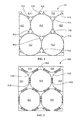
abradable zone 348, shown inFIG.3 , includes at least one layer, but generally includes a plurality ofabradable layers 356 including a fused powder composition 400 (seeFIG. 5 ). Thefused powder composition 400 includes a plurality ofpowder particles 412 fused, melted or joined together by an energy source to form theabradable layer 356. Theabradable zone 348 is applied using any suitable technique, including, but not limited to, an electro-spark deposition (ESD) process, an electron beam welding process, a laser powder fusion welding process, a direct metal laser sintering process, and combinations thereof. As shown inFIG. 4 , in one embodiment, thepre-fused powder composition 401 includes a plurality ofpowder particles 412 andbinder particles 416, dispersed amongst thepowder particles 412. As the energy source is applied to the nominal unit cells ofpowder particles 412, thebinder particles 416 melt or disperse and thepowder particles 412 join together at adjacent surfaces to form theabradable layer 356. In one embodiment, laser beam may be focused on an approximately 2 millimeters to approximately 10 millimeters, or alternatively 3 milliliters to approximately 8 millimeters, or approximately 4 millimeters to approximately 6 millimeters diameter patch ofpowder particles 412. The thermal energy from laser beam generally penetrates approximately 0.2 millimeters to approximately 2 millimeters, or alternatively 0.3 millimeters to approximately 1.8 millimeters to approximately 0.4 millimeters to approximately 1.7 millimeters into thepowder particles 412, thereby simultaneously evolving or volatizingbinder particles 416 from the system and fusingadjacent non-binder particles 412 into fused powder particles 414 (seeFIG. 5 ). - As shown in
FIG. 4 , thepre-fused powder composition 401 for either thetransitional layers 358 or theabradable layers 356 includes a plurality ofpowder particles 412 andbinder particles 416 inter-dispersed amongst thepowder particles 412 with a minimal amount ofvoid space 410 therebetween. As shown inFIG. 4 , there is an optimal packing density between thepowder particles 412 and thebinder particles 416, such that the particle size of thebinder particles 416 is approximately the square root of thepowder particles 412. In another embodiment, thepowder particles 412 andbinder particles 416 can be ordered or randomly dispersed. The plurality ofpowder particles 412 andbinder particles 416 are deposited on thesurface 342 of thesubstrate 344, as a single layer or a plurality of layers using any suitable technique, such as, for example, but not limited to powder deposition. As the energy source is applied to thepre-fused powder composition 401 thebinder particles 416 melt or disintegrate and thepowder particles 412 are joined together at afusion zone 418 to form a plurality of fused powder particles 414 (seeFIG. 5 ) that form atransitional layer 358 or anabradable layer 356. - In one embodiment, the
binder particles 416 are selected from a material capable of melting, disintegrating or vaporing at approximately 150°C or greater. For example, thebinder particle 416 material is, but not limited to, a volatile wax, which vaporizes at approximately 150 °C to approximately 300°C. In one embodiment, the ratio of volume of thebinder particles 416 to thepowder particles 412 is approximately 0.1 percent to approximately 50percent binder particles 416, or alternatively 3 percent to approximately 35percent binder particles 416, or alternatively 5 percent to approximately 25percent binder particle 416. In one embodiment thebinder particles 416 have a particle size of approximately 0.010 millimeters to approximately 0.150 millimeters, or alternatively approximately 0.040 millimeters to approximately 0.100 millimeters, or alternatively approximately 0.050 millimeters to approximately 0.090 millimeters. - For the
transitional layers 358, in one embodiment, the plurality ofpowder particles 412 of thepre-fused powder composition 401 are selected from a material that is substantially the same as material that is used for thesubstrate 344. In this embodiment, the materials of thesubstrate 344 and thetransitional zone 346 are substantially the same, but the density of thetransitional zone 346, because of the method of application, is less than that of thesubstrate 344. Using substantially same material for thesubstrate 344 and thetransitional zone 346 promotes adhesion of thetransitional zone 346 to thesubstrate 344 during high-speed rotation. Thetransitional zone 346 functions as an adhesive region effectively joining or adhering theabradable zone 348 to thesubstrate 344. - The thickness of the
transitional zone 346 is approximately less than 10% of the overall rotating airfoil 114 (blade) length. Thepowder particles 412 of thetransitional zone 346 have a particle size of approximately 0.010 millimeters to approximately 0.150 millimeters, or alternatively approximately 0.040 millimeters to approximately 0.100 millimeters, or alternatively approximately 0.050 millimeters to approximately 0.090 millimeters. - For the
abradable zone 348 which includes at least oneabradable layer 356 the plurality ofpowder particles 412, before fusing, have a particle size of approximately 0.020 millimeters to approximately 0.50 millimeters, or alternatively approximately 0.050 millimeters to approximately 0.300 millimeters, or alternatively approximately 0.080 millimeters to approximately 0.150 millimeters. In one embodiment, thepowder particles 412 in the abradable zone are the same size. - In one embodiment, the
powder particles 412 for theabradable zone 348 contains approximately 10 percent to approximately 60 percent less of the strengthening elements that make up thesubstrate 344. In one embodiment, the material for theabradable zone 348 is a stainless steel having a reduced carbon content compared to that of thesubstrate 344 material selected from stainless steel. In another embodiment, the material for theabradable zone 348 contains a proportionally lower amount of alloying elements to achieve a lower overall strength that that of thesubstrate 344 material. In one embodiment, theabradable zone 348 has a reduced hardness of approximately 140 Brinell to approximately 380 Brinell or alternatively approximately 150 Brinell to approximately 300 Brinell or alternatively approximately 160 Brinell to approximately 250 Brinell. A critical performance aspect of the abradablezone 348 is that the abradable zone does not transmit excess heat into therotating airfoil 114 or blade and does not transmit excess load intorotating airfoil 114, this accomplished by theabradable zone 348 being sacrificed during a tip-rub or similar contact event between the surface of therotating airfoil 114 and thestatic portion 118 or casing of thegas turbine engine 100. - In another embodiment, the
abradable zone 348 has a yield strength of approximately 344 Megapascal to approximately 1724 Megapascal or alternatively approximately 360 Megapascal to approximately 1720 Megapascal or alternatively approximately 400 Megapascal to approximately 1700 Megapascal. In an embodiment, theabradable zone 348 has a thickness of approximately 0.06 millimeters to approximately 100 millimeters or alternatively approximately 0.12 millimeters to approximately 15 millimeters or alternatively approximately 0.8 millimeters to approximately 5 millimeters. - As shown in
FIG. 6 , thepre-fused powder composition 401 for either thetransitional layers 358 or theabradable layers 356 includes a plurality ofpowder particles 412 havingvoid areas 410 randomly dispersed throughout. In this embodiment, the plurality ofpowder particles 412 are randomly dispersed and vary in particle size. The desired density for thetransitional layers 358 andabradable layers 356 determines thepowder particle 412 size, shape, positioning, packing density, and packing order. In another embodiment, thepowder particles 412 are ordered or optimally dispersed as depicted inFIG. 4 . In another embodiment, the plurality ofpowder particles 412 are approximately the same size. After energy is applied, as shown inFIG. 7 , the plurality ofparticles 412 become a fusedpowder composition 400, with a plurality of fusedparticles 414 joined together at afusion zone 418 having a number ofvoid areas 410. Thevoid areas 410 provided the reduced density to thetransitional layers 358 of thetransitional zone 346 andabradable layers 356 of the abradablezone 348. -
FIG. 8 is a schematic of another embodiment of a rotating component of the present disclosure. Theair foil 114 includes asubstrate 344, atransitional zone 346 and anabradable zone 348 including aabradable zone coating 350.FIG. 9 is a cross-section taken along line 9-9 ofFIG. 8 illustrating the various layers of therotatable component 114. As shown inFIG. 9 , and described above in more detail thetransitional zone 346 includes at least one transitional layer applied to thesurface 342 of thesubstrate 344. Thetransitional zone 346 is applied using any suitable method described above. Theabradable zone 348 is applied to thetransitional zone 346 by any suitable method described above. In this embodiment, theabradable zone 348 includes a plurality ofabradable layers 356. The plurality ofabradable layers 356 include a plurality of fusedpowder structures 420. The plurality of fused powder structures include a plurality of fusedpowder particles 414 andvoid areas 410. The geometry of the plurality of fusedpowder structures 420 includes selectively hollowed spheres (as shown inFIG. 9 ), selectively hollowed pyramids, and other various geometries that allow for theabradable zone 348 to remain fixed to thetransitional zone 346 while rotating. The three-dimensional geometries of the fusedpowder structures 420 are created using a 3-D laser sinter process. After theabradable zone 348 is applied anabradable coating layer 350 is applied to theabradable zone 348. Theabradable coating layer 350 or skin prevents unnecessary airflow through thevoid areas 410 of the fused powder structures 420 (seeFIG. 8 ). - The
abradable coating layer 350 material is selected from the same material as the abradable zone. In one embodiment, the abradable coating layer is applied using a 3-D laser sintering process, in another embodiment the abradable coating layer is applied using any other suitable coating process. Theabradable coating layer 350 thickness is approximately 0.06 millimeters to approximately 10 millimeters or alternatively approximately 0.12 millimeters to approximately 8 millimeters or alternatively approximately 0.8 millimeters to approximately 5 millimeters. - In another embodiment, a
coating 222 for arotating airfoil 222 is provided. The coating includes atransitional zone 346 applied to asubstrate 344 and anabradable zone 348 applied to thetransitional zone 346. Theabradable zone 348 includes a plurality ofabradable layers 356 including a plurality of fused powder particles 414 (seeFIG.5 ) or a plurality of fused powder structures 420 (seeFIG. 9 ). In one embodiment, theabradable zone 348 includes anabradable coating layer 350. Thecoating 222 withstands rotational force and theabradable zone 348 is consumed upon contact with astatic portion 118 of agas turbine engine 100. - A method of coating a
rotatable engine component 114 is provided. The method includes providing therotatable engine component 114 having asubstrate 344. Applying atransitional zone 346 to thesurface 342 of thesubstrate 344. Applying anabradable zone 348 to thetransitional zone 346, wherein theabradable zone 348 is consumed upon contact with a static portion 118 (e.g. case liner of a gas turbine engine) of theengine 100. In one embodiment, thetransitional zone 346 is applied using thermal energy. Thetransitional zone 346 acts an intermediate or adhesive layer to keep theabradable zone 348 from detaching from thesubstrate 344 during rotation. In one embodiment, theabradable zone 348 is applied using a laser densification process, a laser powder fusion welding process, a direct-metal laser sintering process, an electron beam welding process, an electrostatic deposition process, and combinations thereof. - In one embodiment, the
surface 342 of thesubstrate 344 of the rotatablegas turbine component 114 is optionally prepared before applying the transitional zone. In repairing thecoating 222, the optional step of preparation includes removal of any remaining existingabradable layers 356 ortransitional layers 358 from thesurface 342 of thesubstrate 344. Examples of processes used for removal are, but not limited to, any method for flattening thesurface 342 of thesubstrate 344, such as, but not limited to, grinding and sanding. - One advantage of an embodiment of the present disclosure includes an engine having tighter clearance control between the blade tip and casing.
- Another advantage of an embodiment of the present disclosure is high compressor efficiency resulting from the tighter clearances of compressor design.
- Another advantage of an embodiment of the present disclosure is robust compressor operation because the air foil damage is removed when tip rub occurs between the air foil tip and casing.
- Another advantage of an embodiment of the present disclosure is that inspections and blending of airfoils in the field is eliminated.
- Yet another advantage of an embodiment of the present disclosure is the abradable tip allows the blade to withstand high speed contact with the casing without suffering detrimental effects associated with tip rub.
- Another advantage of an embodiment of the present disclosure is the compressor can continue to run without causing danger of crack initiation at the airfoil tip or root after a tip rub event.
- While the invention has been described with reference to a preferred embodiment, it will be understood by those skilled in the art that various changes may be made and equivalents may be substituted for elements thereof without departing from the scope of the invention. In addition, many modifications may be made to adapt a particular situation or material to the teachings of the invention without departing from the essential scope thereof. Therefore, it is intended that the invention not be limited to the particular embodiment disclosed as the best mode contemplated for carrying out this invention, but that the invention will include all embodiments falling within the scope of the appended claims.
Claims (16)
- A rotatable engine component (114) comprising:a substrate (344);a transitional zone (346) applied to the substrate (344); andan abradable zone (348) applied to the transitional zone (346), wherein the abradable zone (348) is consumed upon contact with a static portion (118) of the engine (100).
- The rotatable engine component (114) of claim 1, wherein the rotatable engine component is a compressor airfoil (114).
- The rotatable engine component (114) of claim 1 or 2 , wherein the substrate (344) is selected from a substrate material comprising stainless steel alloys, nickel-based alloys, titanium alloys, aluminum alloys, aluminum-lithium alloys, and combinations thereof.
- The rotatable engine component of any of claims 1 to 3 wherein the transitional zone (346) comprises at least one transitional layer of a fused powder composition (400).
- The rotatable engine component (114) of claim 4, wherein the fused powder composition (400) comprises a plurality of powder particles (412).
- The rotatable engine component (114) of claim 5, wherein the plurality of powder particles (412) of the transitional zone (346) are selected from a material that is substantially the same as the substrate material.
- The rotatable engine component (114) of claim 5 or 6, wherein the plurality of powder particles (412) of the transitional zone (346) have a particle size of approximately 0.010 millimeters to approximately 0.150 millimeters.
- The rotatable engine component (114) of any of claims 1 to 7, wherein the abradable zone (348) comprises a plurality of abradable layers (356).
- The rotatable engine component (114) of claim 8, wherein each of the plurality of abradable layers (356) include a plurality of fused powder particles (412), a plurality of fused powder (414) structures, or combinations thereof.
- The rotatable engine component (114) of claim 9, wherein the plurality of fused powder particles (412) of the abradable zone (348) have a particle size of approximately 0.020 millimeters to approximately 0.150 millimeters.
- The rotatable engine component (114) of any preceding claim, wherein the abradable zone (348) has a thickness of approximately 0.06 millimeters to approximately 100 millimeters.
- A method of coating a rotatable engine component (114) comprising:providing the rotatable engine component (114) having a substrate (344);applying a transitional zone (346) to the substrate (344); andapplying an abradable zone (348) to the transitional zone (346), wherein the abradable zone (348) is consumed upon contact with a static portion (118) of an engine (100).
- The method of claim 12, wherein the surface (342) of the substrate (344) of the rotatable component (114) is optionally prepared before applying the transitional zone (346).
- The method of claim 12 or 13, wherein the transitional zone (346) is applied using thermal energy.
- The method of any of claims 12 to 14, wherein the transitional zone (346) has a thickness of approximately less than ten percent of an overall length of a rotating compressor airfoil (114) in the engine (100).
- The method of any of claims 12 to 15, wherein the abradable zone (348) is applied using a laser densification process, a laser powder fusion welding process, a direct-metal laser sintering process, an electron beam welding process, an electrostatic deposition process, and combinations thereof.
Applications Claiming Priority (1)
| Application Number | Priority Date | Filing Date | Title |
|---|---|---|---|
| US13/211,889 US9145787B2 (en) | 2011-08-17 | 2011-08-17 | Rotatable component, coating and method of coating the rotatable component of an engine |
Publications (1)
| Publication Number | Publication Date |
|---|---|
| EP2559861A2 true EP2559861A2 (en) | 2013-02-20 |
Family
ID=46679179
Family Applications (1)
| Application Number | Title | Priority Date | Filing Date |
|---|---|---|---|
| EP20120179580 Withdrawn EP2559861A2 (en) | 2011-08-17 | 2012-08-07 | Rotatable component, coating and method of coating the rotatable component of an engine |
Country Status (3)
| Country | Link |
|---|---|
| US (1) | US9145787B2 (en) |
| EP (1) | EP2559861A2 (en) |
| CN (1) | CN102953763B (en) |
Cited By (1)
| Publication number | Priority date | Publication date | Assignee | Title |
|---|---|---|---|---|
| EP3093097A1 (en) * | 2015-05-11 | 2016-11-16 | United Technologies Corporation | Near net shape abradable seal manufacturing method |
Families Citing this family (17)
| Publication number | Priority date | Publication date | Assignee | Title |
|---|---|---|---|---|
| ES2700788T3 (en) * | 2012-04-04 | 2019-02-19 | MTU Aero Engines AG | Sealing system for a turbomachine |
| US9133712B2 (en) * | 2012-04-24 | 2015-09-15 | United Technologies Corporation | Blade having porous, abradable element |
| EP3002517A1 (en) * | 2014-09-30 | 2016-04-06 | Siemens Aktiengesellschaft | Porous rotating machine component, combustor and manufacturing method |
| US10132185B2 (en) | 2014-11-07 | 2018-11-20 | Rolls-Royce Corporation | Additive process for an abradable blade track used in a gas turbine engine |
| US10450876B2 (en) * | 2015-04-15 | 2019-10-22 | United Technologies Corporation | Abrasive tip blade manufacture methods |
| GB201602685D0 (en) * | 2016-02-16 | 2016-03-30 | Rolls Royce Plc | Manufacture of a drum for a gas turbine engine |
| US10458254B2 (en) * | 2016-11-16 | 2019-10-29 | General Electric Company | Abradable coating composition for compressor blade and methods for forming the same |
| US10294962B2 (en) * | 2017-06-30 | 2019-05-21 | United Technologies Corporation | Turbine engine seal for high erosion environment |
| US10900371B2 (en) | 2017-07-27 | 2021-01-26 | Rolls-Royce North American Technologies, Inc. | Abradable coatings for high-performance systems |
| US10858950B2 (en) | 2017-07-27 | 2020-12-08 | Rolls-Royce North America Technologies, Inc. | Multilayer abradable coatings for high-performance systems |
| US10738644B2 (en) * | 2017-08-30 | 2020-08-11 | General Electric Company | Turbine blade and method of forming blade tip for eliminating turbine blade tip wear in rubbing |
| US10774668B2 (en) * | 2017-09-20 | 2020-09-15 | General Electric Company | Intersage seal assembly for counter rotating turbine |
| US11346232B2 (en) | 2018-04-23 | 2022-05-31 | Rolls-Royce Corporation | Turbine blade with abradable tip |
| US10995623B2 (en) | 2018-04-23 | 2021-05-04 | Rolls-Royce Corporation | Ceramic matrix composite turbine blade with abrasive tip |
| RU2732278C1 (en) * | 2019-04-09 | 2020-09-14 | Публичное акционерное общество "ОДК-Уфимское моторостроительное производственное объединение" | Device for turbojet engine broken turbine blade localization |
| US11428160B2 (en) | 2020-12-31 | 2022-08-30 | General Electric Company | Gas turbine engine with interdigitated turbine and gear assembly |
| US11867082B2 (en) * | 2021-04-21 | 2024-01-09 | General Electric Company | Rotor blade with detachable tip |
Family Cites Families (26)
| Publication number | Priority date | Publication date | Assignee | Title |
|---|---|---|---|---|
| DE3500692A1 (en) * | 1985-01-11 | 1986-07-17 | MTU Motoren- und Turbinen-Union München GmbH, 8000 München | Axial- or radial-rotor blade array with devices for stabilising blade tip play |
| US4867639A (en) | 1987-09-22 | 1989-09-19 | Allied-Signal Inc. | Abradable shroud coating |
| US5644394A (en) | 1994-10-19 | 1997-07-01 | United Technologies Corporation | System for repairing damaged gas turbine engine airfoils |
| US5599166A (en) | 1994-11-01 | 1997-02-04 | United Technologies Corporation | Core for fabrication of gas turbine engine airfoils |
| US5625958A (en) | 1995-09-06 | 1997-05-06 | United Technologies Corporation | Method and a gauge for measuring the service life remaining in a blade |
| US6102656A (en) * | 1995-09-26 | 2000-08-15 | United Technologies Corporation | Segmented abradable ceramic coating |
| US5785492A (en) | 1997-03-24 | 1998-07-28 | United Technologies Corporation | Method and apparatus for sealing a gas turbine stator vane assembly |
| US6641907B1 (en) * | 1999-12-20 | 2003-11-04 | Siemens Westinghouse Power Corporation | High temperature erosion resistant coating and material containing compacted hollow geometric shapes |
| DE59906204D1 (en) | 1998-07-29 | 2003-08-07 | Geesthacht Gkss Forschung | METHOD FOR PRODUCING COMPONENTS BY METAL POWDER INJECTION MOLDING |
| US6206642B1 (en) | 1998-12-17 | 2001-03-27 | United Technologies Corporation | Compressor blade for a gas turbine engine |
| US6630093B1 (en) * | 1999-08-21 | 2003-10-07 | Ronald D. Jones | Method for making freeform-fabricated core composite articles |
| US6533285B2 (en) * | 2001-02-05 | 2003-03-18 | Caterpillar Inc | Abradable coating and method of production |
| US6487863B1 (en) | 2001-03-30 | 2002-12-03 | Siemens Westinghouse Power Corporation | Method and apparatus for cooling high temperature components in a gas turbine |
| US6485262B1 (en) | 2001-07-06 | 2002-11-26 | General Electric Company | Methods and apparatus for extending gas turbine engine airfoils useful life |
| US6532656B1 (en) | 2001-10-10 | 2003-03-18 | General Electric Company | Gas turbine engine compressor blade restoration method |
| US7032279B2 (en) | 2002-10-18 | 2006-04-25 | General Electric Company | Apparatus and methods for repairing compressor airfoils in situ |
| US6916529B2 (en) * | 2003-01-09 | 2005-07-12 | General Electric Company | High temperature, oxidation-resistant abradable coatings containing microballoons and method for applying same |
| WO2005068845A1 (en) * | 2004-01-14 | 2005-07-28 | Ishikawajima-Harima Heavy Industries Co., Ltd. | Compressor, titanium-made rotor blade, jet engine and titanium-made rotor blade producing method |
| US20070104886A1 (en) * | 2005-11-10 | 2007-05-10 | General Electric Company | Electrostatic spray for coating aircraft engine components |
| ATE452218T1 (en) | 2005-09-10 | 2010-01-15 | Schaeffler Kg | WEAR-RESISTANT COATING AND METHOD FOR PRODUCING THE SAME |
| US20100136296A1 (en) * | 2006-11-30 | 2010-06-03 | United Technologies Corporation | Densification of coating using laser peening |
| US7998604B2 (en) * | 2007-11-28 | 2011-08-16 | United Technologies Corporation | Article having composite layer |
| US8210807B2 (en) | 2008-08-28 | 2012-07-03 | United Technologies Corporation | Gas turbine airfoil assemblies and methods of repair |
| US8192168B2 (en) | 2008-09-11 | 2012-06-05 | General Electric Company | Airfoil shape for a compressor blade |
| EP2317078B2 (en) * | 2009-11-02 | 2021-09-01 | Ansaldo Energia IP UK Limited | Abrasive single-crystal turbine blade |
| US8876470B2 (en) * | 2011-06-29 | 2014-11-04 | United Technologies Corporation | Spall resistant abradable turbine air seal |
-
2011
- 2011-08-17 US US13/211,889 patent/US9145787B2/en not_active Expired - Fee Related
-
2012
- 2012-08-07 EP EP20120179580 patent/EP2559861A2/en not_active Withdrawn
- 2012-08-17 CN CN201210295452.8A patent/CN102953763B/en not_active Expired - Fee Related
Non-Patent Citations (1)
| Title |
|---|
| None |
Cited By (1)
| Publication number | Priority date | Publication date | Assignee | Title |
|---|---|---|---|---|
| EP3093097A1 (en) * | 2015-05-11 | 2016-11-16 | United Technologies Corporation | Near net shape abradable seal manufacturing method |
Also Published As
| Publication number | Publication date |
|---|---|
| CN102953763A (en) | 2013-03-06 |
| US9145787B2 (en) | 2015-09-29 |
| CN102953763B (en) | 2016-08-17 |
| US20130045091A1 (en) | 2013-02-21 |
Similar Documents
| Publication | Publication Date | Title |
|---|---|---|
| US9145787B2 (en) | Rotatable component, coating and method of coating the rotatable component of an engine | |
| US8657570B2 (en) | Rotor blade with reduced rub loading | |
| US8356409B2 (en) | Repair method for gas turbine engine components | |
| US8662834B2 (en) | Method for reducing tip rub loading | |
| US8365405B2 (en) | Preforms and related methods for repairing abradable seals of gas turbine engines | |
| EP3095965B1 (en) | Gas turbine engine component and corresponding gas turbine engine | |
| EP2899371B1 (en) | Fan blades with abrasive tips | |
| CN102275058A (en) | Method for repairing gas turbine blades and a gas turbine blade | |
| CN101311497B (en) | The method of centralized positioning cutting on shrouded turbines machine blade | |
| CN101382149A (en) | durable blade | |
| US20110217484A1 (en) | Method for repairing seal segments of rotor/stator seals of a gas turbine | |
| JP2019157202A (en) | Repair method of ceramic coating, ceramic coating, turbine member and gas turbine | |
| CA2766534C (en) | Rotor blade and method for reducing tip rub loading | |
| US20200157953A1 (en) | Composite fan blade with abrasive tip | |
| US9016692B2 (en) | Sealing rings for a labyrinth seal | |
| EP3056676A1 (en) | Turbine engine component, process for coating and modified blade tip | |
| JP6947851B2 (en) | Turbine blades with skiler tips and high density oxide dispersion reinforcement layers | |
| US7850173B2 (en) | Repairable labyrinth seal | |
| US8089028B2 (en) | Methods for repairing gas turbine engine knife edge seals | |
| EP2113633A2 (en) | Method to weld repair blade outer air seals | |
| JP6949026B2 (en) | Repaired turbomachinery parts and corresponding repair methods | |
| JP4496650B2 (en) | Steam turbine | |
| CN102536889B (en) | Compressor blade, possess its turbine and the method suppressing its friction collision | |
| CN102536889A (en) | Compressor blade with flexible tip elements and process therefor |
Legal Events
| Date | Code | Title | Description |
|---|---|---|---|
| PUAI | Public reference made under article 153(3) epc to a published international application that has entered the european phase |
Free format text: ORIGINAL CODE: 0009012 |
|
| AK | Designated contracting states |
Kind code of ref document: A2 Designated state(s): AL AT BE BG CH CY CZ DE DK EE ES FI FR GB GR HR HU IE IS IT LI LT LU LV MC MK MT NL NO PL PT RO RS SE SI SK SM TR |
|
| AX | Request for extension of the european patent |
Extension state: BA ME |
|
| STAA | Information on the status of an ep patent application or granted ep patent |
Free format text: STATUS: THE APPLICATION IS DEEMED TO BE WITHDRAWN |
|
| 18D | Application deemed to be withdrawn |
Effective date: 20180301 |