EP2559845B1 - Système de stimulation multi-réseau à haut débit - Google Patents
Système de stimulation multi-réseau à haut débit Download PDFInfo
- Publication number
- EP2559845B1 EP2559845B1 EP12181091.5A EP12181091A EP2559845B1 EP 2559845 B1 EP2559845 B1 EP 2559845B1 EP 12181091 A EP12181091 A EP 12181091A EP 2559845 B1 EP2559845 B1 EP 2559845B1
- Authority
- EP
- European Patent Office
- Prior art keywords
- condition
- port
- insert
- wellbore
- ports
- Prior art date
- Legal status (The legal status is an assumption and is not a legal conclusion. Google has not performed a legal analysis and makes no representation as to the accuracy of the status listed.)
- Active
Links
- 230000000638 stimulation Effects 0.000 title description 2
- 239000012530 fluid Substances 0.000 claims description 90
- 238000004891 communication Methods 0.000 claims description 33
- 238000000034 method Methods 0.000 claims description 13
- 230000000903 blocking effect Effects 0.000 claims 1
- 230000015572 biosynthetic process Effects 0.000 description 23
- 238000005755 formation reaction Methods 0.000 description 23
- 238000002955 isolation Methods 0.000 description 11
- 229930195733 hydrocarbon Natural products 0.000 description 9
- 239000004215 Carbon black (E152) Substances 0.000 description 7
- 125000001183 hydrocarbyl group Chemical group 0.000 description 6
- 230000008859 change Effects 0.000 description 3
- 150000002430 hydrocarbons Chemical class 0.000 description 3
- 230000008569 process Effects 0.000 description 3
- 230000004913 activation Effects 0.000 description 2
- 230000008878 coupling Effects 0.000 description 2
- 238000010168 coupling process Methods 0.000 description 2
- 238000005859 coupling reaction Methods 0.000 description 2
- 238000004519 manufacturing process Methods 0.000 description 2
- 239000000463 material Substances 0.000 description 2
- 238000003801 milling Methods 0.000 description 2
- 241000282472 Canis lupus familiaris Species 0.000 description 1
- 238000007792 addition Methods 0.000 description 1
- 238000005516 engineering process Methods 0.000 description 1
- 230000006872 improvement Effects 0.000 description 1
- 230000000977 initiatory effect Effects 0.000 description 1
- 238000002347 injection Methods 0.000 description 1
- 239000007924 injection Substances 0.000 description 1
- 230000007246 mechanism Effects 0.000 description 1
- 230000004048 modification Effects 0.000 description 1
- 238000012986 modification Methods 0.000 description 1
- 230000035699 permeability Effects 0.000 description 1
- 230000004044 response Effects 0.000 description 1
- 238000007789 sealing Methods 0.000 description 1
Images


Classifications
-
- E—FIXED CONSTRUCTIONS
- E21—EARTH OR ROCK DRILLING; MINING
- E21B—EARTH OR ROCK DRILLING; OBTAINING OIL, GAS, WATER, SOLUBLE OR MELTABLE MATERIALS OR A SLURRY OF MINERALS FROM WELLS
- E21B34/00—Valve arrangements for boreholes or wells
- E21B34/06—Valve arrangements for boreholes or wells in wells
- E21B34/14—Valve arrangements for boreholes or wells in wells operated by movement of tools, e.g. sleeve valves operated by pistons or wire line tools
- E21B34/142—Valve arrangements for boreholes or wells in wells operated by movement of tools, e.g. sleeve valves operated by pistons or wire line tools unsupported or free-falling elements, e.g. balls, plugs, darts or pistons
-
- E—FIXED CONSTRUCTIONS
- E21—EARTH OR ROCK DRILLING; MINING
- E21B—EARTH OR ROCK DRILLING; OBTAINING OIL, GAS, WATER, SOLUBLE OR MELTABLE MATERIALS OR A SLURRY OF MINERALS FROM WELLS
- E21B43/00—Methods or apparatus for obtaining oil, gas, water, soluble or meltable materials or a slurry of minerals from wells
- E21B43/25—Methods for stimulating production
- E21B43/26—Methods for stimulating production by forming crevices or fractures
-
- E—FIXED CONSTRUCTIONS
- E21—EARTH OR ROCK DRILLING; MINING
- E21B—EARTH OR ROCK DRILLING; OBTAINING OIL, GAS, WATER, SOLUBLE OR MELTABLE MATERIALS OR A SLURRY OF MINERALS FROM WELLS
- E21B2200/00—Special features related to earth drilling for obtaining oil, gas or water
- E21B2200/06—Sleeve valves
-
- E—FIXED CONSTRUCTIONS
- E21—EARTH OR ROCK DRILLING; MINING
- E21B—EARTH OR ROCK DRILLING; OBTAINING OIL, GAS, WATER, SOLUBLE OR MELTABLE MATERIALS OR A SLURRY OF MINERALS FROM WELLS
- E21B43/00—Methods or apparatus for obtaining oil, gas, water, soluble or meltable materials or a slurry of minerals from wells
- E21B43/25—Methods for stimulating production
- E21B43/26—Methods for stimulating production by forming crevices or fractures
- E21B43/267—Methods for stimulating production by forming crevices or fractures reinforcing fractures by propping
Definitions
- a common practice in producing hydrocarbons is to fracture the hydrocarbon bearing formation. Fracturing the hydrocarbon bearing formation increases the overall permeability of the formation and thereby increases hydrocarbon production from the zone fractured. Increasingly a single wellbore may intersect multiple hydrocarbon bearing formations. In these instances each hydrocarbon bearing zone may be isolated from any other and the fracturing operation proceeds sequentially through each zone.
- the fracturing assembly typically includes a tubular string extending generally to the surface, a wellbore isolation valve at the bottom of the string, various sliding sleeves placed at particular intervals along the string, open hole packers spaced along the string to isolate the wellbore into zones, and a top liner packer.
- the fracturing assembly is typically run into the hole with the sliding sleeves closed and the wellbore isolation valve open.
- a setting ball, dart, or other type of plug is deployed into the string.
- a ball may be a ball, dart, or any other acceptable device to form a seal with a seat.
- WO 2012/037645 A1 is prior art under Art. 54(3) EPC and describes an apparatus for fluid treatment of a borehole, the apparatus allowing initial outflow injection of fluids into a wellbore in which it is installed and then is actuable to allow fluid inflow control.
- the apparatus includes: a tubular body, a first port and a second port opened through the wall of the tubular body, the second port having a fluid inflow controller positioned to control the flow of fluid into the tubular body through the port, a sliding sleeve valve in the tubular body moveable from (i) a first position closing the first port and the second port to (ii) a second position closing the second port and permitting fluid flow through the first port and to (iii) a third position closing the first port and permitting fluid flow through the second port; a sleeve actuator for actuating the sliding sleeve valve to move from the first position to the second position in response to a force applied thereto; a releasable lock for locking the sliding sleeve valve in the first position and selected to maintain the sliding sleeve valve in the first position after the force is removed; and a lock release mechanism configured to actuate the releasable lock to release the sliding sleeve valve to move into the third position.
- US 2009/0056934 A1 describes fracturing tools for use in oil and gas wells.
- the fracturing tools have a run-in position and two operational positions.
- a sleeve disposed in the bore of the fracturing tool comprises a sleeve port alignable with a first port in the housing of the frac tool, i.e., the first operational position, during fracturing operations.
- a second port having a restriction member is disposed in the housing and is closed by the sleeve during fracturing operations. After fracturing operations are completed, a return member in the frac tool moves the sleeve from the first operational position to a second operational position for production operations.
- US 2011/192613 A1 describes a downhole sleeve which has an insert movable in the sleeve's bore from a closed condition to an opened condition when a ball dropped in the bore engages an indexing seat in the sliding sleeve.
- the insert prevents communication between the bore and the sleeve's port, while the insert in the opened condition permits communication between the bore and port. Keys of a seat extend into the bore to engage the ball and to move the insert open.
- the keys retract so the ball can pass through the sleeve to another cluster sleeve or to an isolation sleeve of an assembly.
- Insets or buttons disposed in the sleeve's port temporarily maintain fluid pressure in the sleeve's bore so that a cluster of sleeves can be opened before treatment fluid dislodges the button to treat the surrounding formation through the open port.
- a downhole assembly may comprise at least two sliding sleeves.
- Each sliding sleeve may further comprise a housing having an outer diameter, an inner diameter, a first port allowing fluid communication between the inner diameter and the outer diameter, and a second port allowing fluid communication between the inner diameter and the outer diameter longitudinally offset from the first port.
- An insert may be located within the inner diameter of the housing and may have an outer insert diameter, an inner insert diameter, a releasable seat, a shifting profile, and a first position within the housing wherein fluid flow through the first and second ports is blocked.
- a shifting ball may actuate the releasable seat to facilitate movement of the insert between a first position and a second position wherein the insert allows fluid flow through the first port and the shifting ball is released.
- a shifting tool may engage the insert to facilitate movementof the insert between the second position and a third position wherein the insert allows fluid flow through at least the second port.
- the shifting tool may engage the insert to facilitate movement of the insert between the second position and a third position wherein the insert allows fluid flow through the first and the second port.
- the cross-sectional area of the first port may be less than the cross-sectional area of the housing.
- the cross-sectional area of the first port and second ports may be approximately equal to or greater than the cross-sectional area of the housing.
- the shifting tool may be moved by coiled tubing operated from the surface.
- the shifting tool may be moved by a wellbore tractor operated from the surface.
- the shifting profile may be engaged by a shifting tool operated from the wellbore.
- a downhole well fluid assembly according to claim 1.
- the sliding sleeve in the second open condition may block radial fluid communication through the first ports.
- Fluid communication between the central throughbore and the wellbore may be greater in the second open condition than in the first open condition.
- the sliding sleeve in the second open condition may allow radial fluid communication through the first ports.
- the sliding sleeve in the first open condition may block radial fluid communication through the second ports.
- a shifting tool may engage the sliding sleeves to actuate the sliding sleeve between the first condition, the second condition, and the third condition.
- the shifting tool may be operated from the surface.
- the shifting tool may be moved by coiled tubing operated from the surface.
- the shifting tool may be moved by a wellbore tractor operated from the surface.
- the shifting tool may be operated remotely.
- Changing between the first open condition and the second open condition may seal the first port.
- Changing between the first open condition and the second open condition may allow access to both second port and the first port.
- Changing between the first open condition and the second open condition may increase radial fluid flow.
- the sliding sleeve has a movable insert that blocks radial fluid flow through the sliding sleeve when the sliding sleeve is closed.
- Fixed to the insert is a releasable seat that is supported about the seats periphery by the internal diameter of the housing. Upon reaching the first releasable seat the ball can form a seal. The surface fracturing pumps may then apply fluid pressure against the now seated ball and the corresponding releasable seat to shift open the sliding sleevepermanently locking it open.
- the surface fracturing pumps may increase the pressure and fracture the hydrocarbon bearing formation adjacent to the sliding sleeves providing multiple fracturing initiation points in a single stage.
- a cluster of sliding sleeves may be deployed on a tubing string in a wellbore.
- Each sliding sleeve has an inner sleeve or insert movable from a closed condition to multiple opened or partially opened conditions.
- the insert prevents communication between a bore and a port in the sleeve's housing.
- a ball is dropped into the wellbore and pumped to the first sliding sleeve where it forms a seal with the releasable seat.
- Keys or dogs of the insert's seat extend into the bore and engage the dropped ball, providing a seat to allow the insert to be moved open with applied fluid pressure.
- the external diameter of the housing is in fluid communication with the interior portion of the housing through the ports in the housing.
- This other sliding sleeve can be a cluster sleeve that opens with the same ball and allows the ball to pass through after opening.
- the ball can reach an isolation tool or a single shot sliding sleeve further down the tubing string that opens when the ball engages its seat but does not allow the ball to pass through. Operators can deploy various arrangements of cluster and isolation sleeves for different sized balls to treat desired isolated zones of a formation.
- the mill out may include removing portions of sliding sleeve ball seats that are not releasable and any other debris that may be left over from the fracturing process.
- the first set of ports in the sliding sleeve do not have sufficient area to maximize fluid flow through the wellbore to the surface.
- the first set of ports becomes the flow restriction in the well.
- the second set of ports may be configured to add their flow area to that of the first set of ports to achieve an at least equal flow area to that of the tubular string.
- the ports may be configured to match the flow area of the tubular string.
- a typical configuration of a sliding sleeve has at least two sliding sleeves.
- Each sliding sleeve in turn typically having a housing having an outer housing diameter, an inner housing diameter, a first port allowing fluid communication between the inner housing diameter and the outer housing diameter, and a second port longitudinally offset from the first port that allows fluid communication between the inner housing diameter and the outer housing diameter.
- Each sliding sleeve also has an insert typically located within the inner housing diameter.
- Each insert has an outer insert diameter, an inner insert diameter, a releasable seat, and a shifting profile.
- Each insert is typically located in the inner housing diameter so that it has a first position within the inner housing diameter where fluid flow through the at least first and second ports is blocked.
- a shifting ball pumped down from the surface actuates the releasable seat to facilitate movement of the insert between a first position and a second position wherein the insert allows fluid flow through the first port; after the insert is moved from its first position to its second position the shifting ball is released.
- a shifting tool may then be run into the wellbore on coiled tubing, a wellbore tractor, or any other device that may supply the necessary force to actuate the insert from its second position to a third position.
- the shifting tool may be operated from surface as when coiled tubing is used, it may be operated remotely such as by a wellbore tractor on an electric or hydraulic line, or it may be operated by any other remote means that can supply sufficient force to move the insert from one position to any other such as from the second open position to the closed position or from the second open position to the first open position.
- the insert's third position allows fluid flow through at the second port.
- the first and second ports may be arranged such that in the second position fluid flow through the second port may be blocked and when the insert is in the third position fluid flow through the first port may be blocked. In some cases it may be desirable to allow fluid flow through both the first and second ports when the insert is in its third position.
- the first port may consist of a series of ports in approximately the same longitudinal position around the sliding sleeves' housing.
- the second port is longitudinally offset from the first port but may also consist of a series of ports in approximately the same longitudinal position around the sliding sleeves' housing.
- the first port and the second port may not have the same cross-sectional area nor is it necessary that each port within the first ports or second ports have the same cross-sectional area.
- An alternate configuration of a downhole well fluid system is a plurality of sliding sleeves having a central throughbore and attached to tubing string that is run into a wellbore.
- Each of the sliding sleeves is typically actuated by a single ball pumped down the tubing string.
- the sliding sleeves have a closed condition and at least two open conditions and each sliding sleeve is able to be actuated from a closed condition to a first opened condition.
- the closed condition prevents fluid from radially flowing between the central throughbore and the wellbore and the first opened condition allowing radial fluid communication between the central throughbore and the wellbore.
- Each of the sliding sleeves in the opened condition allowing the single ball to pass therethrough.
- Each of the sliding sleeves may be changed from a a first opened condition to a second opened condition.
- the second opened condition typically permitting increased fluid flow between the central throughbore and the wellbore than the first opened condition.
- the ports in the sliding sleeve may be arranged so that the sliding sleeve in the second open condition blocks fluid flow through the first ports.
- the ports may be advisable to arrange the ports such that fluid communication between the central throughbore and the wellbore is greater in the second open condition than in the first open condition.
- the sliding sleeve in the first open condition blocks radial fluid communication through the second ports.
- a shifting tool may be run into the wellbore on coiled tubing, a wellbore tractor, or any other device that may supply the necessary force to actuate a sliding sleeves from its second position to a third position.
- the shifting tool may be operated from surface as when coiled tubing is used, it may be operated remotely such as by a wellbore tractor on an electric or hydraulic line, or it may be operated by any other remote means that can supply sufficient force to move the insert from one position to any other.
- a wellbore fluid treatment method may include deploying at least two sliding sleeves on a tubing string in a wellbore, each of the sliding sleeves having a housing, an outer diameter, an inner diameter, a central throughbore, a first port allowing radial fluid communication between the central throughbore and the wellbore, a second port longitudinally offset from the first port allowing radial fluid communication between the central throughbore and the wellbore, and a closed condition preventing radial fluid communication between the central throughbore and the wellbore.
- a ball is pumped or dropped down the tubing string to change the sliding sleeves from a closed condition to a first open condition allowing access to the first port.
- the ball is then released from the sliding sleeve and in many cases actuates another lower sliding sleeve.
- a shifting tool is run down the tubing string to change the sliding sleeve from the first open condition to a second open condition allowing access to the second port.
- first open condition and the second open condition seals the first port or perhaps changing between the first open condition and the second open condition allows access to both second port and the first port.
- first open condition and the second open condition allows or restricts access to various ports and radial fluid flow may increase or decrease.
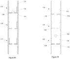
- Figure 1 depicts a schematic view of a wellbore 11 with a single zone and having a fracturing assembly 10 therein.
- the fracturing assembly 10 typically consists of a tubular string 12 extending to the surface 20, an open hole packer 14 near the upper end of the sliding sleeves 16, and a wellbore isolation valve 18.
- the tubular string 12 is connected to the fracturing pumps 30 through the rig 40.
- the fracturing pumps 30 supply the necessary fluid pressure to activate the sliding sleeves 16.
- the open hole packer 14 at the upper end of the sliding sleeves 16 isolates the upper end of the formation zone 22 being fractured.
- a wellbore isolation valve 18 is placed to seal the lower end of the formation zone 22 being fractured.
- the fracturing assembly 10 may be assembled and run into the wellbore 11 for a predetermined distance such that the wellbore isolation valve 18 is past the end of the formation zone 22 to be fractured, the open hole packer 14 is above the formation zone 22, and the sliding sleeves 16 are distributed in the appropriate places along the formation zone 22.
- each of the sliding sleeves 16 are closed, the wellbore isolation valve 18 is open, and the open hole packer 14 is not set.
- the ball 66 forms a seal with seat 52 in sliding sleeve 16,where the sleeve is in a closed position with a type of releasable ball seat 52 such as is used in WEATHERFORD'S MULTI ARRAY STIMULATION SYSTEM, described in US2011/0192613 .
- Figure 3 depicts the sliding sleeve 16 in the open position and includes like reference numbers. As depicted in the cross-section of Figure 3 depicted in Figure 3AA , the sliding sleeve 16 has a housing 50, with an outer diameter 51, an inner diameter 53 defining a longitudinal bore therethrough 54, and having ends 56 and 58 for coupling to the tubular string 12.
- Ports 60 are formed in the housing 50 to allow fluid communication between the interior of the housing 50 and the exterior of the housing 50.
- an inner sleeve or insert 62 Located about the interior of the housing 50 is an inner sleeve or insert 62 having an outer insert diameter 61 and an inner insert diameter 63 that is movable between an open position (see Fig. 3 ) and a closed position (see Fig. 2 ).
- the insert 62 has slots 64 formed about its circumference to accommodate the releasable seat 52.
- the releasable seat 52 is supported about its exterior diameter by the inner diameter of the housing 50.
- the operator uses the fracturing pumps 30 to force a shifting ball 66 down the wellbore 11.
- a seal is formed.
- the fluid pressure above the shifting ball 66 is increased by the fracturing pumps 30 causing the releasable seat 52 and its corresponding insert 62 to move towards the bottom of the wellbore 11.
- the wellbore ports 60 are uncovered allowing radial access between the interior portion of the housing 50 or the housing longitudinal bore 54 and the exterior portion of the housing 50 accessing the formation zone 22.
- the releasable seat 52 reaches an at least partially circumferential slot 68 as depicted in in the cross-section of Figure 3 depicted in Figure 3BB .
- the at least partially circumferential slot 68 may be located in the inner diameter of the housing 50 where typically material has been milled away to increase the inner diameter of the housing 50.
- the releasable seat 52 recesses into the at least partially circumferential slot 68.
- the releasable seat 52 recesses into the at least partially circumferential slot 68 because as the releasable seat 52 and insert 62 move down, the releasable seat 52 is no longer supported by the inner diameter of the housing 53 causing the outer diameter of the releasable seat 67 to move into the at least partially circumferential slot 68 and thereby causing a corresponding increase in the inner diameter 65 of the releasable seat 52 thereby allowing the shifting ball 66 to pass through the sliding sleeve 16.
- sliding sleeves 16 are grouped together such that those sliding sleeves 16 actuated by a particular shifting ball size are located sequentially near one another.
- these sliding sleeves do not have to be sequentially located next to one another.
- sliding sleeves 120 and 122 are located in a tubular string 124 and are actuated by the same sized shifting ball 128.
- sliding sleeves 120 and 122 are placed above and below a third sliding sleeve 126 that is actuated by a different sized but larger shifting ball (not shown).
- the smaller shifting ball 128 can then be pumped down the well where it lands on the first releasable seat 130 in sliding sleeve 120.
- pressure from the fracturing pumps 30 ( Figure 1 ) against the shifting ball 128 and the corresponding releasable seat 130 forces the insert 132 and the first releasable seat 130 downwards until the releasable seat reaches the circumferential slot 134.
- the releasable seat 130 then moves outwardly into the circumferential slot 134 thereby increasing the inner diameter of the releasable seat 130 and releasing the shifting ball 128.
- the releasable seat 136 has a large enough diameter that shifting ball 128 passes through sliding sleeve 126 without actuating sliding sleeve 126.
- the shifting ball 128 will then land on the second releasable seat 138 forcing the insert 140 and the second releasable seat 138 downwards until the releasable seat reaches the circumferential slot 142.
- the second releasable seat 138 then moves outwardly into the circumferential slot 142 thereby increasing the inner diameter of the releasable seat 138 and releasing the shifting ball 128.
- the shifting ball may then seat in the wellbore isolation tool 18 or actuate any other tool to seal against the wellbore11. Fluid is then diverted out through the ports 60 in the sliding sleeves 16 and into the annulus 24 created between the tubular string 12 and the wellbore 11.
- the open hole packer 14 and the packer associated with the wellbore isolation valve 18 may be set above and below the sliding sleeves 16 to isolate the formation zone 22 and the portion of the sliding sleeves 16 from the rest of the wellbore.
- the fracturing pumps 30 are now able to supply fracturing fluid at the proper pressure to fracture only that portion of the formation zone 22 that has been isolated. After the formation 22 has been fractured any hydrocarbons may be produced.
- the port 60 used during the fracturing process has a smaller cross-sectional area than the tubular string12. As any produced fluids travel out of the formation zone 22 and into the tubular string 12 the port 60 becomes a flow restriction for the produced fluids. In order to overcome the potential flow restriction it may be advisable to place a second set of flow ports around the sliding sleeve's housing.
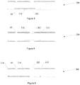
- Figure 5 depicts a cross-sectional view of a sliding sleeve 200 having a port 60 and a second port 202 longitudinally offset from the port 60.
- the insert 210 is in the closed position where radial fluid flow through port 60 and second port 202 is blocked.
- Figure 6 depicts a cross-sectional view of a sliding sleeve 200 having a port 60 and a second port 202 longitudinally offset from the port 60.
- the shifting ball 66 ( Figure 2 ) forms a seal with the releasable seat 52 ( Figure 2 ) to force the insert 210 to move down against a lower stop 212, thus exposing port 60 and allowing radial fluid flow through port 60 between the interior and the exterior of the sliding sleeve 200 and the shifting ball 66 ( Figure 2 ) is released.
- the operator is now able to fracture the formation zone 22 ( Figure 1 ).
- Figure 7 depicts a sliding sleeve 70 with a type of releasable ball seat 72 in the open position allowing fluid communication through the ports 90 between the interior of the housing and the exterior of the housing.
- the sliding sleeve 70 has a housing 74 defining a longitudinal bore 76 therethrough and having ends 78 and 80 for coupling to the tubing string.
- Located about the interior of the housing is an inner sleeve or insert 82 that is movable between an open position and a closed position.
- the insert 82 has slots 84 formed about its circumference to accommodate the releasable seat 72.
- the insert 82 has a profile 88 formed about the inner insert diameter 91.
- the profile 88 is typically formed by circumferentially milling away a portion of material around at least one end of the inner insert diameter 91.
- the releasable seat 72 is supported around the outer diameter of the releasable seat 72 by the inner diameter of the housing 74.
- a snap ring 93 is provided in circumferential slot 92 about the exterior diameter of insert 82. The snap ring 93 latches into circumferential slot 92 about the interior diameter of the housing 74 to retain the insert 82 in an open position.
- the snap ring 93 will retract into circumferential slot 92 until it reaches circumferential slot 94 about the interior diameter of the housing where it will expand into circumferential slot 94 and thereby retaining the insert 82 in the closed position.
- Figure 8A depicts a shifting tool 100 having a radially movable latch 102A to latch into profile 88.
- the shifting tool 100 may be run into the fracturing assembly 10 on coiled tubing 106, by a wellbore tractor, or by any other means that can carry the shifting tool 100 into the fracturing assembly 10.
- the shifting tool may be run into the wellbore 11 with the movable latch in a radially retracted position 102A reducing the outer diameter of the shifting tool 100 and allowing the shifting tool 100 to clear any areas of reduced diameter inside of the fracturing assembly 10.
- Figure 8B depicts a shifting tool 100 with the radially movable latch 102B in its extended position.
- the movable latch is actuated from its radially retracted position 102A to its radially extended position 102B and engages profile 88 ( Figure 7 ) within the insert 82 ( Figure 7 ).
- Tension is then applied to move the shifting tool 100 and thereby insert 82 from its open position to its closed position to block fluid flow between the exterior of the housing 74 through the ports 90 and into the interior of the housing.
- any device such as an electrically (electric line 110) or hydraulically driven wellbore tractor 108 that can provide sufficient force to the shifting tool 100 to shift the insert 82 may be used.
- Figure 9 depicts a cross-sectional view of a sliding sleeve 200 having a port 60 and a second port 202 longitudinally offset from the port 60.
- a shifting tool 100 Figure 8A
- second port has a larger cross-sectional area than port 60.
- Each port 60 and second port 202 may include multiple openings spaced circumferentially around the sliding sleeve. Depending upon the particular characteristics desired second port 202 could have a larger, a smaller, or the same cross-sectional area as port 60. Also depending upon the particular characteristics desired the second port 202 and the port 60 can be opened together or in any order desired.
Landscapes
- Life Sciences & Earth Sciences (AREA)
- Engineering & Computer Science (AREA)
- Geology (AREA)
- Mining & Mineral Resources (AREA)
- Physics & Mathematics (AREA)
- Environmental & Geological Engineering (AREA)
- Fluid Mechanics (AREA)
- General Life Sciences & Earth Sciences (AREA)
- Geochemistry & Mineralogy (AREA)
- Multiple-Way Valves (AREA)
- Quick-Acting Or Multi-Walled Pipe Joints (AREA)
- Pipe Accessories (AREA)
Claims (15)
- Ensemble de fluide de puits de fond, comprenant :plusieurs manchons coulissants (200) comportant un alésage de passage central et disposés sur un train de tubes pouvant être déployé dans un puits de forage ;chacun des manchons coulissants (200) comportant un boîtier (50) ayant un diamètre extérieur (51), un diamètre intérieur (53), un alésage de passage central, et des premier et deuxième orifices (60, 202), les premier et deuxième orifices (60, 202) étant décalés longitudinalement l'un de l'autre et établissant une communication entre l'alésage de passage central et le puits de forage ;chacun des manchons coulissants (200) comportant un insert (210) et un siège rétractable (52) disposé dans l'alésage de passage central et pouvant être actionné par une seule bille (128) pouvant être déployée le long du train de tubes, le siège rétractable (52) pouvant se déplacer entre un état d'accrochage et un état de passage, le siège rétractable (52) étant rétracté dans une fente (68) de l'alésage de passage central dans l'état de passage, le siège rétractable (52) étant supporté autour de son diamètre extérieur par le diamètre intérieur (53) du boîtier (50) dans l'état d'accrochage ;chacun des inserts (210) dans les manchons coulissants (200) étant actionné par une seule bille (128) s'engageant dans le siège rétractable (52) dans l'état d'accrochage et se déplaçant dans une direction longitudinale, d'un état fermé vers un premier état ouvert, l'insert (210) empêchant une communication de fluide entre l'alésage de passage central et le puits de forage à travers les premier et deuxième orifices (60, 202) dans l'état fermé, l'insert (210) permettant une première communication de fluide entre l'alésage de passage central et le puits de forage à travers le premier orifice (60) dans le premier état ouvert ;chacun des sièges rétractables (52) dans les manchons coulissants (200) se trouvant dans l'état de passage dans le premier état ouvert et permettant le passage de la seule bille (128) ; etchacun des inserts (210) dans les manchons coulissants (200) pouvant se déplacer en outre dans une direction longitudinale opposée, du premier état ouvert vers un deuxième état ouvert, le deuxième état ouvert permettant une deuxième communication de fluide entre l'alésage de passage central et le puits de forage à travers au moins le deuxième orifice (202).
- Ensemble de fond de trou selon la revendication 1, dans lequel le manchon coulissant (200) bloque la première communication de fluide à travers le premier orifice (60) dans le deuxième état ouvert, et optionnellement dans lequel la deuxième communication de fluide entre l'alésage de passage central et le puits de forage est plus grande dans le deuxième état ouvert à travers le deuxième orifice (202) que dans la première communication de fluide dans le premier état ouvert à travers le premier orifice (60).
- Ensemble de fond de trou selon les revendications 1 ou 2, dans lequel :l'insert (210) dans le manchon coulissant (200) permet la première communication de fluide à travers le premier orifice (60) dans le deuxième état ouvert ; et/oul'insert (210) dans le manchon coulissant (200) bloque la deuxième communication de fluide à travers le deuxième orifice (202) dans le premier état ouvert.
- Ensemble de fond de trou selon l'une quelconque des revendications 1 à 3, comprenant en outre un outil de déplacement (100) configuré pour s'engager dans les inserts (210) dans les manchons coulissants (200) afin d'actionner le manchon coulissant (200) dans la direction longitudinale opposée, du premier état ouvert vers le deuxième état ouvert.
- Ensemble de fond de trou selon la revendication 4, dans lequel :l'outil de déplacement (100) est actionné depuis la surface ; et/oul'outil de déplacement (100) est déplacé par un tube de production enroulé actionné depuis la surface ; et/oul'outil de déplacement (100) est déplacé par un tracteur du puits de forage actionné depuis la surface ; et/oul'outil de déplacement (100) est actionné à distance.
- Ensemble de fond de trou selon l'une quelconque des revendications précédentes, dans lequel chaque manchon coulissant (200) comprend :le boîtier (50) ayant le diamètre extérieur (51), le diamètre intérieur (53) pour l'alésage de passage central, le premier orifice (60) permettant une communication de fluide entre le diamètre intérieur (53) et le diamètre extérieur (51), et le deuxième orifice (202) permettant une communication de fluide entre le diamètre intérieur (53) et le diamètre extérieur (51) ;l'insert (210) bloquant un écoulement de fluide à travers les premier et deuxième orifices (60, 202) dans l'état fermé dans le boîtier (50) ;le siège rétractable (52) pouvant être engagé par la seule bille (128) dans l'état d'accrochage afin de déplacer l'insert (210) dans la direction longitudinale, de l'état fermé vers le premier état ouvert, l'insert (210) permettant un écoulement de fluide à travers le premier orifice (60) dans le premier état ouvert, et bloquant l'écoulement de fluide à travers le deuxième orifice (202), le siège rétractable (52) pouvant se déplacer vers l'état de passage, lorsque l'insert (210) se trouve dans le premier état ouvert et libère la seule bille (128) ;l'insert (210) pouvant en outre être engagé par un outil de déplacement (100) afin de déplacer l'insert (210) dans la direction longitudinale opposée, du premier état ouvert vers le deuxième état ouvert, dans lequel l'insert (210) permet un écoulement de fluide à travers au moins le deuxième orifice (202) dans le deuxième état ouvert ;dans lequel le siège rétractable (52) peut être engagé par la seule bille (128) dans l'état d'accrochage de chacun des manchons coulissants (200).
- Ensemble de fond de trou selon la revendication 6, dans lequel l'insert (210) expose les premier et deuxième orifices (60, 202) dans la troisième position et permet l'écoulement de fluide à travers le premier orifice (60) et le deuxième orifice (202).
- Ensemble de fond de trou selon les revendications 6 ou 7, dans lequel la surface de section transversale du premier orifice (60) est inférieure à la surface de section transversale du boîtier (50).
- Ensemble de fond de trou selon les revendications 6, 7 ou 8, dans lequel la surface de section transversale combinée du premier orifice (60) et du deuxième orifice (202) est à peu près égale ou supérieure à la surface de section transversale du boîtier (50).
- Ensemble de fond de trou selon l'une quelconque des revendications 6 à 9, dans lequel :l'outil de déplacement (100) est déplacé par le tube de production enroulé actionné depuis la surface ; et/oul'outil de déplacement (100) est déplacé par un tracteur du puits de forage actionné depuis la surface.
- Ensemble de fond de trou selon l'une quelconque des revendications 6 à 10, dans lequel l'insert comprend un profil de déplacement engagé par l'outil de déplacement (100) actionné depuis le puits de forage.
- Procédé de traitement d'un fluide de puits de forage, comprenant les étapes ci-dessous :déploiement d'au moins deux manchons coulissants (200) selon l'une quelconque des revendications précédentes sur un train de tubes dans un puits de forage ;retombée d'une bille (128) le long du train de tubes ;utilisation de la bille (128) pour engager les sièges rétractables (52) dans l'état d'accrochage et pour déplacer les inserts (210) dans chacun des manchons coulissants (200) dans une direction longitudinale, de l'état fermé vers un premier état ouvert, permettant une communication de fluide à travers les premiers orifices (60) ;libération de la bille (128) des manchons coulissants (200), les sièges rétractables (52) se trouvant dans l'état de passage ;descente d'un outil de déplacement (100) le long du train de tubes ; etutilisation de l'outil de déplacement (100) pour déplacer l'insert (210) dans au moins un des manchons coulissants (200) dans une direction longitudinale opposée, du premier état ouvert vers un deuxième état ouvert, permettant une communication de fluide travers au moins le deuxième orifice (202).
- Procédé selon la revendication 12, dans lequel le déplacement de l'insert (210) dans la direction longitudinale opposée, du premier état ouvert vers le deuxième état ouvert, scelle le premier orifice (60).
- Procédé selon les revendications 12 ou 13, dans lequel le déplacement de l'insert (210) dans la direction longitudinale opposée, du premier état ouvert vers le deuxième état ouvert, expose les premier et deuxième orifices (60, 202) et permet une communication de fluide à travers le deuxième orifice (202) et le premier orifice (60) à la fois.
- Procédé selon les revendications 12, 13 ou 14, dans lequel le déplacement de l'insert (210) dans la direction longitudinale opposée, du premier état ouvert vers le deuxième état ouvert, accroît l'écoulement de fluide, par suite du fait que le deuxième orifice (202) présente une surface d'écoulement supérieure au premier orifice (60), et/ou l'insert (210) permet l'écoulement de fluide à travers les premiers orifices (60) en plus de l'écoulement du fluide à travers les deuxièmes orifices (202) dans le deuxième état ouvert.
Applications Claiming Priority (1)
| Application Number | Priority Date | Filing Date | Title |
|---|---|---|---|
| US201161525525P | 2011-08-19 | 2011-08-19 |
Publications (3)
| Publication Number | Publication Date |
|---|---|
| EP2559845A2 EP2559845A2 (fr) | 2013-02-20 |
| EP2559845A3 EP2559845A3 (fr) | 2015-08-26 |
| EP2559845B1 true EP2559845B1 (fr) | 2020-07-08 |
Family
ID=46717781
Family Applications (1)
| Application Number | Title | Priority Date | Filing Date |
|---|---|---|---|
| EP12181091.5A Active EP2559845B1 (fr) | 2011-08-19 | 2012-08-20 | Système de stimulation multi-réseau à haut débit |
Country Status (5)
| Country | Link |
|---|---|
| US (1) | US9523261B2 (fr) |
| EP (1) | EP2559845B1 (fr) |
| AU (1) | AU2012216239B2 (fr) |
| CA (1) | CA2785542C (fr) |
| RU (1) | RU2604525C2 (fr) |
Families Citing this family (18)
| Publication number | Priority date | Publication date | Assignee | Title |
|---|---|---|---|---|
| US9353599B2 (en) * | 2012-11-09 | 2016-05-31 | Watson Well Solutions, Llc | Pressure response fracture port tool for use in hydraulic fracturing applications |
| US9995112B2 (en) | 2013-11-27 | 2018-06-12 | Weatherford Technology Holdings, Llc | Method and apparatus for treating a wellbore |
| NO342718B1 (no) * | 2014-08-19 | 2018-07-30 | Frac Tech As | Ventilsystem for et produksjonsrør i en brønn |
| US9951596B2 (en) | 2014-10-16 | 2018-04-24 | Exxonmobil Uptream Research Company | Sliding sleeve for stimulating a horizontal wellbore, and method for completing a wellbore |
| CN104727779B (zh) * | 2015-03-31 | 2017-03-08 | 中国石油集团渤海钻探工程有限公司 | 小通径滑套用开关工具 |
| BR112018004292B1 (pt) * | 2015-09-04 | 2022-07-05 | National Oilwell Varco, L.P | Conjunto para incorporar em uma coluna de completação, sistema de completação de múltiplos estágios para um orifício de poço, e, método para estimular múltiplos estágios em um orifício de poço |
| US10082003B2 (en) | 2016-05-16 | 2018-09-25 | Baker Hughes, A Ge Company, Llc | Through tubing diverter for multi-lateral treatment without top string removal |
| CA2994290C (fr) | 2017-11-06 | 2024-01-23 | Entech Solution As | Methode et manchon de stimulation destines a la completion de puits dans un puits de forage souterrain |
| US20190242215A1 (en) * | 2018-02-02 | 2019-08-08 | Baker Hughes, A Ge Company, Llc | Wellbore treatment system |
| US10648285B2 (en) * | 2018-05-18 | 2020-05-12 | Baker Hughes, A Ge Company, Llc | Fracturing system and method |
| MX2021005199A (es) | 2018-11-09 | 2021-07-15 | Flowserve Man Co | Dispositivos de intercambio de fluidos y controles, sistemas y metodos relacionados. |
| CA3119069A1 (fr) | 2018-11-09 | 2020-05-14 | Flowserve Management Company | Dispositifs d'echange de fluide et commandes, systemes et procedes associes |
| WO2020097553A1 (fr) | 2018-11-09 | 2020-05-14 | Flowserve Management Company | Dispositifs d'échange de fluides et systèmes et procédés associés |
| MX2021005196A (es) | 2018-11-09 | 2021-07-15 | Flowserve Man Co | Metodos y valvulas que incluyen caracteristicas de descarga. |
| MX2021005197A (es) | 2018-11-09 | 2021-07-15 | Flowserve Man Co | Dispositivos de intercambio de fluidos y controles, sistemas y metodos relacionados. |
| CN112997010B (zh) | 2018-11-09 | 2023-03-24 | 芙罗服务管理公司 | 用于在流体交换设备中使用的活塞以及相关设备、系统和方法 |
| AU2020401951A1 (en) | 2019-12-12 | 2022-05-19 | Flowserve Pte. Ltd. | Fluid exchange devices and related controls, systems, and methods |
| RU2740460C1 (ru) * | 2020-06-26 | 2021-01-14 | Общество с ограниченной ответственностью "Российская инновационная топливно-энергетическая компания" (ООО "РИТЭК") | Устройство для проведения многостадийного гидроразрыва пласта и способ проведения многостадийного гидроразрыва пласта при помощи этого устройства |
Family Cites Families (26)
| Publication number | Priority date | Publication date | Assignee | Title |
|---|---|---|---|---|
| US5146992A (en) * | 1991-08-08 | 1992-09-15 | Baker Hughes Incorporated | Pump-through pressure seat for use in a wellbore |
| US6644412B2 (en) * | 2001-04-25 | 2003-11-11 | Weatherford/Lamb, Inc. | Flow control apparatus for use in a wellbore |
| US6907936B2 (en) * | 2001-11-19 | 2005-06-21 | Packers Plus Energy Services Inc. | Method and apparatus for wellbore fluid treatment |
| US7096954B2 (en) * | 2001-12-31 | 2006-08-29 | Schlumberger Technology Corporation | Method and apparatus for placement of multiple fractures in open hole wells |
| US8167047B2 (en) * | 2002-08-21 | 2012-05-01 | Packers Plus Energy Services Inc. | Method and apparatus for wellbore fluid treatment |
| US7387165B2 (en) * | 2004-12-14 | 2008-06-17 | Schlumberger Technology Corporation | System for completing multiple well intervals |
| US7322417B2 (en) * | 2004-12-14 | 2008-01-29 | Schlumberger Technology Corporation | Technique and apparatus for completing multiple zones |
| US7575062B2 (en) * | 2006-06-09 | 2009-08-18 | Halliburton Energy Services, Inc. | Methods and devices for treating multiple-interval well bores |
| US20070284106A1 (en) * | 2006-06-12 | 2007-12-13 | Kalman Mark D | Method and apparatus for well drilling and completion |
| US7681645B2 (en) * | 2007-03-01 | 2010-03-23 | Bj Services Company | System and method for stimulating multiple production zones in a wellbore |
| AU2008287022B2 (en) | 2007-08-13 | 2013-12-19 | Baker Hughes Incorporated | Multi-position valve for fracturing and sand control and associated completion methods |
| US7703510B2 (en) | 2007-08-27 | 2010-04-27 | Baker Hughes Incorporated | Interventionless multi-position frac tool |
| US8826985B2 (en) * | 2009-04-17 | 2014-09-09 | Baker Hughes Incorporated | Open hole frac system |
| US8245788B2 (en) * | 2009-11-06 | 2012-08-21 | Weatherford/Lamb, Inc. | Cluster opening sleeves for wellbore treatment and method of use |
| US8215411B2 (en) * | 2009-11-06 | 2012-07-10 | Weatherford/Lamb, Inc. | Cluster opening sleeves for wellbore treatment and method of use |
| CA2776560A1 (fr) | 2009-12-16 | 2011-06-23 | Packers Plus Energy Services Inc. | Raccord double femelle de fond de trou comportant une soupape a manchon actionnable hydrauliquement |
| US20110284232A1 (en) * | 2010-05-24 | 2011-11-24 | Baker Hughes Incorporated | Disposable Downhole Tool |
| US8297358B2 (en) * | 2010-07-16 | 2012-10-30 | Baker Hughes Incorporated | Auto-production frac tool |
| WO2012037645A1 (fr) | 2010-09-22 | 2012-03-29 | Packers Plus Energy Services Inc. | Outil de fracturation de forage de puits assurant une régulation d'entrée de fluide |
| BR112013032427A2 (pt) * | 2011-06-20 | 2017-01-17 | Packers Plus Energy Serv Inc | sub-kobe com controle de influxo, coluna de tubulação de furo de poço e método |
| US9080420B2 (en) * | 2011-08-19 | 2015-07-14 | Weatherford Technology Holdings, Llc | Multiple shift sliding sleeve |
| US9394773B2 (en) * | 2012-01-27 | 2016-07-19 | Weatherford Technology Holdings, Llc | Resettable ball seat |
| US8931557B2 (en) * | 2012-07-09 | 2015-01-13 | Halliburton Energy Services, Inc. | Wellbore servicing assemblies and methods of using the same |
| US9080421B2 (en) * | 2012-08-07 | 2015-07-14 | Halliburton Energy Services, Inc. | Mechanically adjustable flow control assembly |
| US9353599B2 (en) * | 2012-11-09 | 2016-05-31 | Watson Well Solutions, Llc | Pressure response fracture port tool for use in hydraulic fracturing applications |
| US9546537B2 (en) * | 2013-01-25 | 2017-01-17 | Halliburton Energy Services, Inc. | Multi-positioning flow control apparatus using selective sleeves |
-
2012
- 2012-08-08 US US13/569,391 patent/US9523261B2/en active Active
- 2012-08-14 CA CA2785542A patent/CA2785542C/fr active Active
- 2012-08-16 AU AU2012216239A patent/AU2012216239B2/en not_active Ceased
- 2012-08-17 RU RU2012135477/03A patent/RU2604525C2/ru active
- 2012-08-20 EP EP12181091.5A patent/EP2559845B1/fr active Active
Non-Patent Citations (1)
| Title |
|---|
| None * |
Also Published As
| Publication number | Publication date |
|---|---|
| RU2012135477A (ru) | 2014-02-27 |
| AU2012216239B2 (en) | 2015-04-09 |
| EP2559845A3 (fr) | 2015-08-26 |
| EP2559845A2 (fr) | 2013-02-20 |
| RU2604525C2 (ru) | 2016-12-10 |
| AU2012216239A1 (en) | 2013-03-07 |
| CA2785542A1 (fr) | 2013-02-19 |
| US20130043043A1 (en) | 2013-02-21 |
| US9523261B2 (en) | 2016-12-20 |
| CA2785542C (fr) | 2015-11-17 |
Similar Documents
| Publication | Publication Date | Title |
|---|---|---|
| EP2559845B1 (fr) | Système de stimulation multi-réseau à haut débit | |
| CA2785510C (fr) | Manchon coulissant multiposition | |
| US9874067B2 (en) | Sliding sleeve sub and method and apparatus for wellbore fluid treatment | |
| US8215411B2 (en) | Cluster opening sleeves for wellbore treatment and method of use | |
| EP2941531B1 (fr) | Vanne de dérivation de manchon de coulissement pour traitement de puits | |
| CA2997105C (fr) | Appareil, systemes et procedes destines a la stimulation de multiples etages | |
| CA2984951C (fr) | Manchon coulissant muni d'un mecanisme d'indexation et manchon expansible | |
| WO2017100615A1 (fr) | Système pour placer un traceur dans un puits | |
| WO2014082054A1 (fr) | Système de complétion, de stimulation et de production | |
| WO2015017337A1 (fr) | Ensemble soupape | |
| WO2016073609A1 (fr) | Procédé et appareil pour opérations de récupération secondaire dans des formations d'hydrocarbures |
Legal Events
| Date | Code | Title | Description |
|---|---|---|---|
| PUAI | Public reference made under article 153(3) epc to a published international application that has entered the european phase |
Free format text: ORIGINAL CODE: 0009012 |
|
| 17P | Request for examination filed |
Effective date: 20120820 |
|
| AK | Designated contracting states |
Kind code of ref document: A2 Designated state(s): AL AT BE BG CH CY CZ DE DK EE ES FI FR GB GR HR HU IE IS IT LI LT LU LV MC MK MT NL NO PL PT RO RS SE SI SK SM TR |
|
| AX | Request for extension of the european patent |
Extension state: BA ME |
|
| RAP1 | Party data changed (applicant data changed or rights of an application transferred) |
Owner name: WEATHERFORD/LAMB, INC. |
|
| RAP1 | Party data changed (applicant data changed or rights of an application transferred) |
Owner name: WEATHERFORD TECHNOLOGY HOLDINGS, LLC |
|
| PUAL | Search report despatched |
Free format text: ORIGINAL CODE: 0009013 |
|
| AK | Designated contracting states |
Kind code of ref document: A3 Designated state(s): AL AT BE BG CH CY CZ DE DK EE ES FI FR GB GR HR HU IE IS IT LI LT LU LV MC MK MT NL NO PL PT RO RS SE SI SK SM TR |
|
| AX | Request for extension of the european patent |
Extension state: BA ME |
|
| RIC1 | Information provided on ipc code assigned before grant |
Ipc: E21B 43/26 20060101AFI20150721BHEP Ipc: E21B 34/14 20060101ALI20150721BHEP |
|
| STAA | Information on the status of an ep patent application or granted ep patent |
Free format text: STATUS: EXAMINATION IS IN PROGRESS |
|
| 17Q | First examination report despatched |
Effective date: 20171115 |
|
| GRAP | Despatch of communication of intention to grant a patent |
Free format text: ORIGINAL CODE: EPIDOSNIGR1 |
|
| STAA | Information on the status of an ep patent application or granted ep patent |
Free format text: STATUS: GRANT OF PATENT IS INTENDED |
|
| INTG | Intention to grant announced |
Effective date: 20200121 |
|
| GRAS | Grant fee paid |
Free format text: ORIGINAL CODE: EPIDOSNIGR3 |
|
| GRAA | (expected) grant |
Free format text: ORIGINAL CODE: 0009210 |
|
| STAA | Information on the status of an ep patent application or granted ep patent |
Free format text: STATUS: THE PATENT HAS BEEN GRANTED |
|
| 111Z | Information provided on other rights and legal means of execution |
Free format text: AL AT BE BG CH CY CZ DE DK EE ES FI FR GB GR HR HU IE IS IT LT LU LV MC MK MT NL NO PL PT RO RS SE SI SK SM TR AL AT BE BG CH CY CZ DE DK EE ES FI FR GB GR HR HU IE IS IT LT LU LV MC MK MT NL NO PL PT RO RS SE SI SK SM TR Effective date: 20200511 |
|
| AK | Designated contracting states |
Kind code of ref document: B1 Designated state(s): AL AT BE BG CH CY CZ DE DK EE ES FI FR GB GR HR HU IE IS IT LI LT LU LV MC MK MT NL NO PL PT RO RS SE SI SK SM TR |
|
| REG | Reference to a national code |
Ref country code: GB Ref legal event code: FG4D |
|
| REG | Reference to a national code |
Ref country code: CH Ref legal event code: EP Ref country code: AT Ref legal event code: REF Ref document number: 1288654 Country of ref document: AT Kind code of ref document: T Effective date: 20200715 |
|
| REG | Reference to a national code |
Ref country code: DE Ref legal event code: R096 Ref document number: 602012071103 Country of ref document: DE |
|
| REG | Reference to a national code |
Ref country code: IE Ref legal event code: FG4D |
|
| REG | Reference to a national code |
Ref country code: LT Ref legal event code: MG4D |
|
| REG | Reference to a national code |
Ref country code: NO Ref legal event code: T2 Effective date: 20200708 |
|
| REG | Reference to a national code |
Ref country code: AT Ref legal event code: MK05 Ref document number: 1288654 Country of ref document: AT Kind code of ref document: T Effective date: 20200708 |
|
| REG | Reference to a national code |
Ref country code: NL Ref legal event code: MP Effective date: 20200708 |
|
| REG | Reference to a national code |
Ref country code: GB Ref legal event code: 732E Free format text: REGISTERED BETWEEN 20201126 AND 20201202 |
|
| PG25 | Lapsed in a contracting state [announced via postgrant information from national office to epo] |
Ref country code: ES Free format text: LAPSE BECAUSE OF FAILURE TO SUBMIT A TRANSLATION OF THE DESCRIPTION OR TO PAY THE FEE WITHIN THE PRESCRIBED TIME-LIMIT Effective date: 20200708 Ref country code: BG Free format text: LAPSE BECAUSE OF FAILURE TO SUBMIT A TRANSLATION OF THE DESCRIPTION OR TO PAY THE FEE WITHIN THE PRESCRIBED TIME-LIMIT Effective date: 20201008 Ref country code: GR Free format text: LAPSE BECAUSE OF FAILURE TO SUBMIT A TRANSLATION OF THE DESCRIPTION OR TO PAY THE FEE WITHIN THE PRESCRIBED TIME-LIMIT Effective date: 20201009 Ref country code: AT Free format text: LAPSE BECAUSE OF FAILURE TO SUBMIT A TRANSLATION OF THE DESCRIPTION OR TO PAY THE FEE WITHIN THE PRESCRIBED TIME-LIMIT Effective date: 20200708 Ref country code: PT Free format text: LAPSE BECAUSE OF FAILURE TO SUBMIT A TRANSLATION OF THE DESCRIPTION OR TO PAY THE FEE WITHIN THE PRESCRIBED TIME-LIMIT Effective date: 20201109 Ref country code: FI Free format text: LAPSE BECAUSE OF FAILURE TO SUBMIT A TRANSLATION OF THE DESCRIPTION OR TO PAY THE FEE WITHIN THE PRESCRIBED TIME-LIMIT Effective date: 20200708 Ref country code: LT Free format text: LAPSE BECAUSE OF FAILURE TO SUBMIT A TRANSLATION OF THE DESCRIPTION OR TO PAY THE FEE WITHIN THE PRESCRIBED TIME-LIMIT Effective date: 20200708 Ref country code: SE Free format text: LAPSE BECAUSE OF FAILURE TO SUBMIT A TRANSLATION OF THE DESCRIPTION OR TO PAY THE FEE WITHIN THE PRESCRIBED TIME-LIMIT Effective date: 20200708 Ref country code: HR Free format text: LAPSE BECAUSE OF FAILURE TO SUBMIT A TRANSLATION OF THE DESCRIPTION OR TO PAY THE FEE WITHIN THE PRESCRIBED TIME-LIMIT Effective date: 20200708 |
|
| PG25 | Lapsed in a contracting state [announced via postgrant information from national office to epo] |
Ref country code: LV Free format text: LAPSE BECAUSE OF FAILURE TO SUBMIT A TRANSLATION OF THE DESCRIPTION OR TO PAY THE FEE WITHIN THE PRESCRIBED TIME-LIMIT Effective date: 20200708 Ref country code: PL Free format text: LAPSE BECAUSE OF FAILURE TO SUBMIT A TRANSLATION OF THE DESCRIPTION OR TO PAY THE FEE WITHIN THE PRESCRIBED TIME-LIMIT Effective date: 20200708 Ref country code: RS Free format text: LAPSE BECAUSE OF FAILURE TO SUBMIT A TRANSLATION OF THE DESCRIPTION OR TO PAY THE FEE WITHIN THE PRESCRIBED TIME-LIMIT Effective date: 20200708 Ref country code: IS Free format text: LAPSE BECAUSE OF FAILURE TO SUBMIT A TRANSLATION OF THE DESCRIPTION OR TO PAY THE FEE WITHIN THE PRESCRIBED TIME-LIMIT Effective date: 20201108 |
|
| REG | Reference to a national code |
Ref country code: DE Ref legal event code: R119 Ref document number: 602012071103 Country of ref document: DE |
|
| REG | Reference to a national code |
Ref country code: GB Ref legal event code: 732E Free format text: REGISTERED BETWEEN 20210225 AND 20210303 |
|
| PG25 | Lapsed in a contracting state [announced via postgrant information from national office to epo] |
Ref country code: NL Free format text: LAPSE BECAUSE OF FAILURE TO SUBMIT A TRANSLATION OF THE DESCRIPTION OR TO PAY THE FEE WITHIN THE PRESCRIBED TIME-LIMIT Effective date: 20200708 |
|
| REG | Reference to a national code |
Ref country code: CH Ref legal event code: PL |
|
| PG25 | Lapsed in a contracting state [announced via postgrant information from national office to epo] |
Ref country code: MC Free format text: LAPSE BECAUSE OF FAILURE TO SUBMIT A TRANSLATION OF THE DESCRIPTION OR TO PAY THE FEE WITHIN THE PRESCRIBED TIME-LIMIT Effective date: 20200708 Ref country code: LU Free format text: LAPSE BECAUSE OF NON-PAYMENT OF DUE FEES Effective date: 20200820 Ref country code: RO Free format text: LAPSE BECAUSE OF FAILURE TO SUBMIT A TRANSLATION OF THE DESCRIPTION OR TO PAY THE FEE WITHIN THE PRESCRIBED TIME-LIMIT Effective date: 20200708 Ref country code: SM Free format text: LAPSE BECAUSE OF FAILURE TO SUBMIT A TRANSLATION OF THE DESCRIPTION OR TO PAY THE FEE WITHIN THE PRESCRIBED TIME-LIMIT Effective date: 20200708 Ref country code: IT Free format text: LAPSE BECAUSE OF FAILURE TO SUBMIT A TRANSLATION OF THE DESCRIPTION OR TO PAY THE FEE WITHIN THE PRESCRIBED TIME-LIMIT Effective date: 20200708 Ref country code: LI Free format text: LAPSE BECAUSE OF NON-PAYMENT OF DUE FEES Effective date: 20200831 Ref country code: EE Free format text: LAPSE BECAUSE OF FAILURE TO SUBMIT A TRANSLATION OF THE DESCRIPTION OR TO PAY THE FEE WITHIN THE PRESCRIBED TIME-LIMIT Effective date: 20200708 Ref country code: CZ Free format text: LAPSE BECAUSE OF FAILURE TO SUBMIT A TRANSLATION OF THE DESCRIPTION OR TO PAY THE FEE WITHIN THE PRESCRIBED TIME-LIMIT Effective date: 20200708 Ref country code: DK Free format text: LAPSE BECAUSE OF FAILURE TO SUBMIT A TRANSLATION OF THE DESCRIPTION OR TO PAY THE FEE WITHIN THE PRESCRIBED TIME-LIMIT Effective date: 20200708 Ref country code: CH Free format text: LAPSE BECAUSE OF NON-PAYMENT OF DUE FEES Effective date: 20200831 |
|
| PLBE | No opposition filed within time limit |
Free format text: ORIGINAL CODE: 0009261 |
|
| STAA | Information on the status of an ep patent application or granted ep patent |
Free format text: STATUS: NO OPPOSITION FILED WITHIN TIME LIMIT |
|
| REG | Reference to a national code |
Ref country code: BE Ref legal event code: MM Effective date: 20200831 |
|
| PG25 | Lapsed in a contracting state [announced via postgrant information from national office to epo] |
Ref country code: AL Free format text: LAPSE BECAUSE OF FAILURE TO SUBMIT A TRANSLATION OF THE DESCRIPTION OR TO PAY THE FEE WITHIN THE PRESCRIBED TIME-LIMIT Effective date: 20200708 |
|
| 26N | No opposition filed |
Effective date: 20210409 |
|
| PG25 | Lapsed in a contracting state [announced via postgrant information from national office to epo] |
Ref country code: SK Free format text: LAPSE BECAUSE OF FAILURE TO SUBMIT A TRANSLATION OF THE DESCRIPTION OR TO PAY THE FEE WITHIN THE PRESCRIBED TIME-LIMIT Effective date: 20200708 |
|
| PG25 | Lapsed in a contracting state [announced via postgrant information from national office to epo] |
Ref country code: DE Free format text: LAPSE BECAUSE OF NON-PAYMENT OF DUE FEES Effective date: 20210302 Ref country code: FR Free format text: LAPSE BECAUSE OF NON-PAYMENT OF DUE FEES Effective date: 20200908 |
|
| PG25 | Lapsed in a contracting state [announced via postgrant information from national office to epo] |
Ref country code: IE Free format text: LAPSE BECAUSE OF NON-PAYMENT OF DUE FEES Effective date: 20200820 Ref country code: SI Free format text: LAPSE BECAUSE OF FAILURE TO SUBMIT A TRANSLATION OF THE DESCRIPTION OR TO PAY THE FEE WITHIN THE PRESCRIBED TIME-LIMIT Effective date: 20200708 Ref country code: BE Free format text: LAPSE BECAUSE OF NON-PAYMENT OF DUE FEES Effective date: 20200831 |
|
| REG | Reference to a national code |
Ref country code: GB Ref legal event code: 732E Free format text: REGISTERED BETWEEN 20210812 AND 20210818 |
|
| PGFP | Annual fee paid to national office [announced via postgrant information from national office to epo] |
Ref country code: NO Payment date: 20210810 Year of fee payment: 10 Ref country code: GB Payment date: 20210714 Year of fee payment: 10 |
|
| PG25 | Lapsed in a contracting state [announced via postgrant information from national office to epo] |
Ref country code: TR Free format text: LAPSE BECAUSE OF FAILURE TO SUBMIT A TRANSLATION OF THE DESCRIPTION OR TO PAY THE FEE WITHIN THE PRESCRIBED TIME-LIMIT Effective date: 20200708 Ref country code: MT Free format text: LAPSE BECAUSE OF FAILURE TO SUBMIT A TRANSLATION OF THE DESCRIPTION OR TO PAY THE FEE WITHIN THE PRESCRIBED TIME-LIMIT Effective date: 20200708 Ref country code: CY Free format text: LAPSE BECAUSE OF FAILURE TO SUBMIT A TRANSLATION OF THE DESCRIPTION OR TO PAY THE FEE WITHIN THE PRESCRIBED TIME-LIMIT Effective date: 20200708 |
|
| PG25 | Lapsed in a contracting state [announced via postgrant information from national office to epo] |
Ref country code: MK Free format text: LAPSE BECAUSE OF FAILURE TO SUBMIT A TRANSLATION OF THE DESCRIPTION OR TO PAY THE FEE WITHIN THE PRESCRIBED TIME-LIMIT Effective date: 20200708 |
|
| REG | Reference to a national code |
Ref country code: NO Ref legal event code: MMEP |
|
| GBPC | Gb: european patent ceased through non-payment of renewal fee |
Effective date: 20220820 |
|
| PG25 | Lapsed in a contracting state [announced via postgrant information from national office to epo] |
Ref country code: NO Free format text: LAPSE BECAUSE OF NON-PAYMENT OF DUE FEES Effective date: 20220831 |
|
| PG25 | Lapsed in a contracting state [announced via postgrant information from national office to epo] |
Ref country code: GB Free format text: LAPSE BECAUSE OF NON-PAYMENT OF DUE FEES Effective date: 20220820 |