EP2559842A1 - A method of directing vertical drillings - Google Patents
A method of directing vertical drillings Download PDFInfo
- Publication number
- EP2559842A1 EP2559842A1 EP20120177324 EP12177324A EP2559842A1 EP 2559842 A1 EP2559842 A1 EP 2559842A1 EP 20120177324 EP20120177324 EP 20120177324 EP 12177324 A EP12177324 A EP 12177324A EP 2559842 A1 EP2559842 A1 EP 2559842A1
- Authority
- EP
- European Patent Office
- Prior art keywords
- inclination
- string
- tool
- drilling
- boring tool
- Prior art date
- Legal status (The legal status is an assumption and is not a legal conclusion. Google has not performed a legal analysis and makes no representation as to the accuracy of the status listed.)
- Granted
Links
Images

Classifications
-
- E—FIXED CONSTRUCTIONS
- E21—EARTH DRILLING; MINING
- E21B—EARTH DRILLING, e.g. DEEP DRILLING; OBTAINING OIL, GAS, WATER, SOLUBLE OR MELTABLE MATERIALS OR A SLURRY OF MINERALS FROM WELLS
- E21B7/00—Special methods or apparatus for drilling
- E21B7/04—Directional drilling
- E21B7/10—Correction of deflected boreholes
-
- E—FIXED CONSTRUCTIONS
- E21—EARTH DRILLING; MINING
- E21B—EARTH DRILLING, e.g. DEEP DRILLING; OBTAINING OIL, GAS, WATER, SOLUBLE OR MELTABLE MATERIALS OR A SLURRY OF MINERALS FROM WELLS
- E21B47/00—Survey of boreholes or wells
- E21B47/02—Determining slope or direction
- E21B47/022—Determining slope or direction of the borehole, e.g. using geomagnetism
-
- E—FIXED CONSTRUCTIONS
- E21—EARTH DRILLING; MINING
- E21B—EARTH DRILLING, e.g. DEEP DRILLING; OBTAINING OIL, GAS, WATER, SOLUBLE OR MELTABLE MATERIALS OR A SLURRY OF MINERALS FROM WELLS
- E21B7/00—Special methods or apparatus for drilling
- E21B7/04—Directional drilling
- E21B7/06—Deflecting the direction of boreholes
- E21B7/067—Deflecting the direction of boreholes with means for locking sections of a pipe or of a guide for a shaft in angular relation, e.g. adjustable bent sub
Definitions
- the present invention relates to a method for directing vertical drillings; more particularly, the invention relates to a method for restoring the verticality of a drilling.
- the higher precision equipment used hitherto for vertical drillings includes equipment which makes use of an inclinometer (typically a triaxial accelerometer) associated with a compass (triaxial magnetometer). Inclinometer and compass are usually contained in a special rod forming a so-called down-hole assembly (or unit). As is known, the inclinometer provides the value of the inclination with respect to the vertical, while the compass indicates the azimuthal angle of the direction containing this inclination.
- an inclinometer typically a triaxial accelerometer
- compass triaxial magnetometer
- Inclinometer and compass are usually contained in a special rod forming a so-called down-hole assembly (or unit).
- the inclinometer provides the value of the inclination with respect to the vertical, while the compass indicates the azimuthal angle of the direction containing this inclination.
- the tool In order to reposition drilling in its nominal direction, and therefore restore the verticality of the borehole, a deviation must be imparted to the tool in the opposite direction to that of the inclination detected.
- the tool in order to correct the direction of the drilling, i.e. deviate it, the tool is connected to the drill string by means of a deviation connecting member in the form of an elbow sleeve, referred to in the sector as "bent sub".
- the bent sub is arranged between the tool and the string so that the axis of the tool is angularly offset by a few degrees (generally 1 to 3 degrees) with respect to the axis of the drill string.
- the information made available by the compass is used.
- the compass does not always function correctly; this may be due to magnetic disturbances induced by metallic bodies or by electric currents flowing in the vicinity of the drilling.
- the compass may not be permanently contained inside the special tool-holder rod (usually a non-magnetic stainless-steel rod), but must be lowered to the bottom of the excavation whenever a measurement is performed and then removed in order to start the drilling again. Consequently, the correct orientation of the compass with respect to the bent sub and the boring tool is not always readily obtainable.
- the compass must be removed and repositioned with great accuracy.
- the instrument must be locked angularly in a given fixed angular position with respect to the elbow of the bent sub.
- a guiding and connection device called a "mule shoe" which is lowered inside the down-hole assembly. The mule shoe guides the compass into the correct angular position and prevents it from rotating with respect to the tool bit.
- the orientation of the bent sub in the correct direction may therefore be difficult or, in some situations, even impossible.
- the precision of the drilling, and therefore the need to correct deviations from the vertical is of fundamental importance in many applications, for example in the construction of partitions at a depth of more than 40 metres, consisting of posts which are arranged alongside one another and which must overlap by a few centimetres (2-3 cm) in order to ensure the continuity and the impermeability of the construction work.
- the abovementioned method moreover requires that the compass sensors should be arranged very close to the elbow in order to detect with a high degree of accuracy the inclination and orientation of the bent sub. Owing to this proximity, the compass is affected by the magnetic disturbances of the hammer body. The angular data made available by the compass (through a method known as "magnetic tool face orientation", MTFO) may therefore not be used during orientation of the tool face.
- MTFO magnetic tool face orientation
- the compass error is within acceptable limits and may be corrected by means of several readings, for an evaluation of the orientation of the tool face it is necessary to resort to a method which is not subject to major errors so as to be able to correct the deviation in the shortest possible vertical space and with the maximum efficiency.
- a general object of the present invention is to perform precise directional drilling.
- a particular object of the invention is to propose a directional drilling method which allows orientation of the tool with a sequence of rapid operations.
- a further object is to calculate with precision the position of the bottom of the hole.
- Another particular object of the invention is to perform precise directional drillings using a hydraulic hammer.
- FIGS. 1 to 4 show four different angular positions, angularly offset or rotated through 90°, of a down-hole assembly 10.
- the assembly 10 is located at the bottom of a borehole F which is inclined at an angle If with respect to the vertical.
- the assembly 10 comprises a boring tool 11 consisting, advantageously, of a hydraulic hammer.
- the choice of this type of tool is not to be regarded as limiting the invention; the invention is suitable for being implemented also using other types of boring tools.
- One of the main advantages provided by the invention consists, however, in the possibility of also using this particularly effective tool, i.e. the hydraulic hammer, for performing directional drilling into hard deep-lying rock.
- the down-hole assembly 10 comprises a bent sub 12 which rigidly connects the boring tool 11 to the hollow bottom rod 13 of the drill string.
- a probe 14 for example a tracing or guide sensor or probe, such as Paratrack® or PTK, is lowered into the internal cavity of the bottom rod 13.
- the probe 14 may consist of any instrument containing an inclinometer and a compass indicated schematically by 15 in Figures 1-4 .
- the compass is a triaxial magnetometer of the type already used per se in the sector of directional drilling.
- the bent sub generally has an elbow defining an obtuse angle generally ranging between 177 and 179 degrees.
- the method of the present invention in order to correct directional errors during drilling, it is periodically necessary to stop drilling at different depths and perform, at each depth level reached, a plurality (in this case four) of recordings in order to measure the inclination of the probe in each of the four angular positions rotated through 90°.
- the object of these measurements is to:
- the expression "tool face” indicates a point on the periphery of the bottom end situated on the concave side of the bent sub; more particularly, the “tool face” is the side lying in that plane which passes through the longitudinal axis of the hammer and which defines a minimum obtuse angle between the longitudinal axis of the hammer and the longitudinal axis of the drill string.
- the “tool face” is the part or side of the tool which must be directed upwards in order to raise drilling upwards.
- the angular position of Figure 1 is that in which the inclination of the tool is maximum.
- the inclination recorded by the inclinometer is greater than or smaller than, respectively, the real inclination If of the hole. This is due to the asymmetry induced by the bent sub.
- the arithmetic average of the values Is 0 , Is 90 , Is 180 and Is 270 gives, as a result, the real inclination If of the hole.
- the values of the angles Is 0 , Is 90 , Is 180 and Is 270 compensate each other.
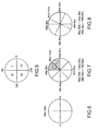
- the maximum inclination value detected from among the values Is 0 , Is 90 , Is 180 and Is 270 indicates, in the azimuthal plane, the quadrant in which the tool face is located.
- the string is rotated, without causing it to move vertically, in such a way as to direct it into the angular position which indicated the maximum inclination value, which in this example is the position 0.
- the angular position at 0° is the "absolute maximum inclination" position.
- Figures 6, 7 and 8 show other possible situations.
- the situation shown in Figure 6 refers to an example where the absolute maximum value is detected in the 90° position, while in the 270° position, the minimum value is measured, and in the 180° and 0° positions two intermediate values are measured.
- Figure 7 refers to an example where two maximum values which are practically equal are measured at 0° and 90°, so that the absolute maximum value will be situated at the halfway point of the quadrant I (at about 45°).
- the maximum value is measured at 90° and the minimum value at 270°; since the intermediate value measured at 0° is slightly greater than the (lesser intermediate) value measured at 180°, the absolute maximum value will be situated at the halfway point of the quadrant I, in an angular position closer to 90° than to 0°.
- selected angular position is used to designate either the angular position taken by the drill string when the maximum inclination value is detected, or an angular position between two angular positions at which two maximum inclination values have been detected.
- the instrument 14 including compass 15 is extracted from the string and the boring tool is then made to penetrate or sink into the ground a short distance, i.e. about a few tens of centimetres, without rotation of the drill string.
- This feeding movement is performed by imparting to the string small rotary reciprocations in the so-called "twist" mode, oscillating about the selected angular orientation position (in this example the position shown in Figure 1 ).
- driving of the tool kept with its tool face directed downwards ( Figure 1 ) causes it to penetrate in such a way as to reduce its inclination and bring it back into alignment with the vertical.
- Twist mode feeding may be carried out either manually by using a joystick for controlling rotation of the drill string or, as an alternative, by activating an automatic control which automatically inverts the flux of the hydraulic drive that causes the string to rotate, making it undergo reciprocating oscillations having a constant amplitude generally comprised between 20 and 40 degrees.
- the tool After advancing along the abovementioned short section in twist mode, the tool is in a sunken position, with the drill string still approximately orientated in the aforesaid selected angular position.
- the instrument 14, 15 is lowered again into the down-hole assembly and the inclination of the hole is detected again in order to check whether, following the aforementioned corrective operation, the verticality has been restored. If this is the case, should the inclinometer signal a condition of verticality or at least an inclination suitable for the excavation requirements, rotation of the string is activated again in order to continue drilling. If this is not the case, the sequence of verticality correction operations described above is repeated (detection of the inclination values in four equally spaced angular positions, orientation of the string in the maximum inclination position, feeding in twist mode).
- Advancement of the tool in the twist mode is optional.
- the tool if the tool is a hammer, the tool may be advanced causing the hammer to follow percussive motions, without rotating the drill string.
- the tool if the boring tool is associated with a mud motor, the tool may be advanced by activating the mud motor without rotating the drill string. In either case, upon reaching the lowered or sunken position, the string is oriented in the aforesaid selected angular position.
- the proximity of the inclinometer to the drilling face is essential in order to achieve a high degree of precision.
- mud motors tend not to be used since this type of tool has a considerable length (generally greater than 3.5 m, but greater than 4.5 m in the case of diameters of more than 4").
- a hydraulic (air or water) hammer able to make a 6" hole measures about 1 m.
- Correction of the verticality is therefore performed without use of the compass 15.
- the compass is used instead to determine the instantaneous spatial position reached by the boring tool face. This operation may, however, also be performed without being negatively affected by the magnetic disturbances which are the cause of measurement errors in the conventional operating methods.
- the directional drilling method which uses a bent sub associated with a down-hole hammer poses two types of problem:
- the first type of problem (A) is solved as a result of the readings carried out of the inclination and azimuth values as per the algorithm shown further below.
- the definition of the correct azimuth (B') is solved by means of symmetrical compensation of the azimuth readings as per the algorithm shown further below and, (B"), (definition of the correct tool face orientation - TFO) by means of the method described above which defines the Absolute Maximum Inclination.
- the invention is not limited to the embodiment described and illustrated here, but is to be regarded as an example of the method; the invention may instead be subject to modifications in terms of forms, dimensions, arrangement of parts, constructional details and apparatus used. For example, the number of measurements of the inclination at the same height, and therefore the angle between the various measurement positions, may differ from that shown here.
Landscapes
- Geology (AREA)
- Life Sciences & Earth Sciences (AREA)
- Engineering & Computer Science (AREA)
- Mining & Mineral Resources (AREA)
- Physics & Mathematics (AREA)
- Environmental & Geological Engineering (AREA)
- Fluid Mechanics (AREA)
- General Life Sciences & Earth Sciences (AREA)
- Geochemistry & Mineralogy (AREA)
- Geophysics (AREA)
- Earth Drilling (AREA)
- Production Of Liquid Hydrocarbon Mixture For Refining Petroleum (AREA)
- Heat Treatment Of Strip Materials And Filament Materials (AREA)
- Drilling And Exploitation, And Mining Machines And Methods (AREA)
Abstract
Description
- The present invention relates to a method for directing vertical drillings; more particularly, the invention relates to a method for restoring the verticality of a drilling.
- The higher precision equipment used hitherto for vertical drillings includes equipment which makes use of an inclinometer (typically a triaxial accelerometer) associated with a compass (triaxial magnetometer). Inclinometer and compass are usually contained in a special rod forming a so-called down-hole assembly (or unit). As is known, the inclinometer provides the value of the inclination with respect to the vertical, while the compass indicates the azimuthal angle of the direction containing this inclination.
- In order to reposition drilling in its nominal direction, and therefore restore the verticality of the borehole, a deviation must be imparted to the tool in the opposite direction to that of the inclination detected. For this purpose, in order to correct the direction of the drilling, i.e. deviate it, the tool is connected to the drill string by means of a deviation connecting member in the form of an elbow sleeve, referred to in the sector as "bent sub". The bent sub is arranged between the tool and the string so that the axis of the tool is angularly offset by a few degrees (generally 1 to 3 degrees) with respect to the axis of the drill string.
- Hitherto, in order to determine the azimuthal direction in which the so-called tool face must be oriented in order to restore the verticality of the excavation, the information made available by the compass is used. In order to orient correctly the directional tool, it is therefore indispensable for the compass to indicate the right direction. However, the compass does not always function correctly; this may be due to magnetic disturbances induced by metallic bodies or by electric currents flowing in the vicinity of the drilling.
- Moreover, with the excavation equipment which is most widely used, the compass may not be permanently contained inside the special tool-holder rod (usually a non-magnetic stainless-steel rod), but must be lowered to the bottom of the excavation whenever a measurement is performed and then removed in order to start the drilling again. Consequently, the correct orientation of the compass with respect to the bent sub and the boring tool is not always readily obtainable. In particular, on each occasion the compass must be removed and repositioned with great accuracy. The instrument must be locked angularly in a given fixed angular position with respect to the elbow of the bent sub. For this purpose it is necessary to use a guiding and connection device called a "mule shoe" which is lowered inside the down-hole assembly. The mule shoe guides the compass into the correct angular position and prevents it from rotating with respect to the tool bit.
- It is indispensable to remove the instrument in particular if boring is performed by means of a hydraulic hammer. This type of tool, which is particularly effective, in fact produces impacts and vibrations which rapidly destroy the compass if it is not removed from the string. Moreover, the high pressures which are required for operation of the hammer may result in the infiltration of water into the data supply/transmission line of the instrument itself.
- The orientation of the bent sub in the correct direction may therefore be difficult or, in some situations, even impossible. The precision of the drilling, and therefore the need to correct deviations from the vertical, is of fundamental importance in many applications, for example in the construction of partitions at a depth of more than 40 metres, consisting of posts which are arranged alongside one another and which must overlap by a few centimetres (2-3 cm) in order to ensure the continuity and the impermeability of the construction work.
- The abovementioned method moreover requires that the compass sensors should be arranged very close to the elbow in order to detect with a high degree of accuracy the inclination and orientation of the bent sub. Owing to this proximity, the compass is affected by the magnetic disturbances of the hammer body. The angular data made available by the compass (through a method known as "magnetic tool face orientation", MTFO) may therefore not be used during orientation of the tool face. Therefore, although in the calculation of the spatial position of the tool face, the compass error is within acceptable limits and may be corrected by means of several readings, for an evaluation of the orientation of the tool face it is necessary to resort to a method which is not subject to major errors so as to be able to correct the deviation in the shortest possible vertical space and with the maximum efficiency.
- A general object of the present invention, therefore, is to perform precise directional drilling. A particular object of the invention is to propose a directional drilling method which allows orientation of the tool with a sequence of rapid operations. A further object is to calculate with precision the position of the bottom of the hole. Another particular object of the invention is to perform precise directional drillings using a hydraulic hammer.
- This object, together with other objects and advantages, which will be understood more clearly from a reading of the ensuing description, is achieved according to the invention by a method which includes the operating steps defined in the accompanying claims.
- A preferred, but non-limiting embodiment of the method according to the invention will now be described with reference to the accompanying drawings, in which:
-
Figures 1-4 are schematic vertically sectioned views of a down-hole assembly of a drilling apparatus, shown in different operating positions during execution of a method according to the invention; -
Figures 1A-4A are schematic top plan views of the assembly shown inFigures 1-4 ; -
Figures 5-8 are diagrams showing angular positions of a boring tool of the apparatus shown inFigures 1-4 ; -
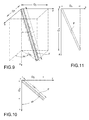
Figures 9, 10 and 11 are schematic views of a borehole section, with an indication of the parameters used by an algorithm proposed for calculation of the position of the bottom of the borehole. - With reference to
Figures 1 to 4 , these show four different angular positions, angularly offset or rotated through 90°, of a down-hole assembly 10. Theassembly 10 is located at the bottom of a borehole F which is inclined at an angle If with respect to the vertical. Theassembly 10 comprises aboring tool 11 consisting, advantageously, of a hydraulic hammer. The choice of this type of tool is not to be regarded as limiting the invention; the invention is suitable for being implemented also using other types of boring tools. One of the main advantages provided by the invention consists, however, in the possibility of also using this particularly effective tool, i.e. the hydraulic hammer, for performing directional drilling into hard deep-lying rock. - The down-
hole assembly 10 comprises abent sub 12 which rigidly connects theboring tool 11 to thehollow bottom rod 13 of the drill string. Aprobe 14, for example a tracing or guide sensor or probe, such as Paratrack® or PTK, is lowered into the internal cavity of thebottom rod 13. Both the probe and the bent sub and the hydraulic hammer are known in the art and do not need to be described in detail here. It should merely be pointed out that theprobe 14 may consist of any instrument containing an inclinometer and a compass indicated schematically by 15 inFigures 1-4 . Preferably, the compass is a triaxial magnetometer of the type already used per se in the sector of directional drilling. The bent sub generally has an elbow defining an obtuse angle generally ranging between 177 and 179 degrees. - According to the method of the present invention, in order to correct directional errors during drilling, it is periodically necessary to stop drilling at different depths and perform, at each depth level reached, a plurality (in this case four) of recordings in order to measure the inclination of the probe in each of the four angular positions rotated through 90°. The object of these measurements is to:
- calculate the local inclination i of the hole and its orientation in the azimuthal plane xy;
- determine, at least approximately, the direction or at least the segment or quadrant into which the so-called "tool face" must be oriented in order to correct the inclination and reposition drilling vertically.
- In the drilling sector, the expression "tool face" indicates a point on the periphery of the bottom end situated on the concave side of the bent sub; more particularly, the "tool face" is the side lying in that plane which passes through the longitudinal axis of the hammer and which defines a minimum obtuse angle between the longitudinal axis of the hammer and the longitudinal axis of the drill string. In other words, the "tool face" is the part or side of the tool which must be directed upwards in order to raise drilling upwards.
- Once a borehole section has been completed, drilling is stopped and the
probe 14 is lowered inside thehollow bottom rod 13. The value of the inclination Is0 is measured and then the string is rotated (without moving it further downwards) through 90°, and measurement of the inclination is repeated, obtaining the inclination value Is90. This operation is repeated a further two times, rotating the string each time through 90° and measuring the inclination, thus obtaining the inclination values Is180 and Is270. The values detected are obtained, in each angular position, from the algebraic sum of the inclination If of the hole and the inclination Is of the probe. The inclination If of the hole is constant for each measurement performed at the same depth, while the inclination of the probe varies, when the string is rotated, owing to the fold in the bent sub. Still with reference toFigures 1-4 , during the analysis of the inclinations the following are recorded: - 1. a maximum value (0° position)
- 2. two intermediate values (90° and 270° positions) and
- 3. a minimum value (180° position).
- In the example shown in
Figures 1-4 , the angular position ofFigure 1 is that in which the inclination of the tool is maximum. In the "0°" and "180°" positions, the inclination recorded by the inclinometer is greater than or smaller than, respectively, the real inclination If of the hole. This is due to the asymmetry induced by the bent sub. The arithmetic average of the values Is0, Is90, Is180 and Is270 gives, as a result, the real inclination If of the hole. When calculating the average, in fact, the values of the angles Is0, Is90, Is180 and Is270 compensate each other. - The maximum inclination value detected from among the values Is0, Is90, Is180 and Is270 indicates, in the azimuthal plane, the quadrant in which the tool face is located.
- In order to restore the verticality, first the string is rotated, without causing it to move vertically, in such a way as to direct it into the angular position which indicated the maximum inclination value, which in this example is the
position 0. In the example shown inFigures 1-4 the angular position at 0° is the "absolute maximum inclination" position. -
Figures 6, 7 and 8 show other possible situations. With reference to the quadrants and the angular positions indicated in the diagram ofFigure 5 , the situation shown inFigure 6 refers to an example where the absolute maximum value is detected in the 90° position, while in the 270° position, the minimum value is measured, and in the 180° and 0° positions two intermediate values are measured.Figure 7 refers to an example where two maximum values which are practically equal are measured at 0° and 90°, so that the absolute maximum value will be situated at the halfway point of the quadrant I (at about 45°). In the example shown inFigure 8 , the maximum value is measured at 90° and the minimum value at 270°; since the intermediate value measured at 0° is slightly greater than the (lesser intermediate) value measured at 180°, the absolute maximum value will be situated at the halfway point of the quadrant I, in an angular position closer to 90° than to 0°. - In the following, the expression "selected angular position" is used to designate either the angular position taken by the drill string when the maximum inclination value is detected, or an angular position between two angular positions at which two maximum inclination values have been detected.
- Once the drill string has been rotated so as to reach the selected angular position, the
instrument 14 includingcompass 15 is extracted from the string and the boring tool is then made to penetrate or sink into the ground a short distance, i.e. about a few tens of centimetres, without rotation of the drill string. This feeding movement is performed by imparting to the string small rotary reciprocations in the so-called "twist" mode, oscillating about the selected angular orientation position (in this example the position shown inFigure 1 ). Owing to the angle of the bent sub, as is known to those skilled in the art, driving of the tool kept with its tool face directed downwards (Figure 1 ) causes it to penetrate in such a way as to reduce its inclination and bring it back into alignment with the vertical. Twist mode feeding, per se known, may be carried out either manually by using a joystick for controlling rotation of the drill string or, as an alternative, by activating an automatic control which automatically inverts the flux of the hydraulic drive that causes the string to rotate, making it undergo reciprocating oscillations having a constant amplitude generally comprised between 20 and 40 degrees. - After advancing along the abovementioned short section in twist mode, the tool is in a sunken position, with the drill string still approximately orientated in the aforesaid selected angular position. At this point, the
instrument - Advancement of the tool in the twist mode is optional. According to another embodiment of the method, if the tool is a hammer, the tool may be advanced causing the hammer to follow percussive motions, without rotating the drill string. In accordance with an alternative embodiment, if the boring tool is associated with a mud motor, the tool may be advanced by activating the mud motor without rotating the drill string. In either case, upon reaching the lowered or sunken position, the string is oriented in the aforesaid selected angular position.
- The proximity of the inclinometer to the drilling face is essential in order to achieve a high degree of precision. The greater the proximity to the face, the greater will be the capacity to measure precisely any deviations thereof. For this reason, in order to perform the drilling of rock, where a particularly high precision is required, mud motors tend not to be used since this type of tool has a considerable length (generally greater than 3.5 m, but greater than 4.5 m in the case of diameters of more than 4"). By using a down-hole hammer together with a bent sub it is possible to drastically reduce this length. A hydraulic (air or water) hammer able to make a 6" hole measures about 1 m.
- As can be understood, with the method according to the present invention, it is possible to correct the direction of the excavation, restoring its verticality, practically in any conditions and for any initial inclination. It may be applied to any instrument equipped with an inclinometer. It is not affected by interference due to the Earth's magnetic field. It is not affected by the drilling length and may therefore be applied also to drillings performed in the mineral sector. In order to implement the method, a conventional "mule shoe" connection is not required, since the tool face may be suitably directed in order to restore the verticality of the drilling independently of operation of the compass.
- Correction of the verticality is therefore performed without use of the
compass 15. The compass is used instead to determine the instantaneous spatial position reached by the boring tool face. This operation may, however, also be performed without being negatively affected by the magnetic disturbances which are the cause of measurement errors in the conventional operating methods. - The directional drilling method which uses a bent sub associated with a down-hole hammer poses two types of problem:
- A) problems associated with the asymmetrical form of the assembly, on account of the angle of the bent sub, which results in falsification of the inclinometric and azimuthal measurements;
- B) problems associated with the magnetic disturbance induced by the metallic mass of the down-hole hammer which results in false angular values;
- B') in the azimuths (i.e. in the angular value of the direction of the hole projected in the azimuthal plane xy);
- B") in the magnetic orientation of the tool face: MTFO (magnetic tool face orientation).
- The first type of problem (A) is solved as a result of the readings carried out of the inclination and azimuth values as per the algorithm shown further below. As regards the problems associated with the magnetic disturbances, the definition of the correct azimuth (B') is solved by means of symmetrical compensation of the azimuth readings as per the algorithm shown further below and, (B"), (definition of the correct tool face orientation - TFO) by means of the method described above which defines the Absolute Maximum Inclination.
- The problem (A) of identifying the correct inclination is associated with the bending effect of the bent sub, which falsifies the values of the inclination (
Figures 1-4 ) and the azimuth of the down-hole assembly 10. - For this reason a system for averaging the adjacent readings, based on the following algorithm for calculating the offset value of the rod end and consequently the position of the tool face along the axes x, y and z, is proposed.
- Assuming that:
- I0, I90, I180, I270 are the inclination values detected for the four positions of the string, angularly equally spaced at 90°;
- Az0, Az90, Az180, Az270 are the azimuth values detected by means of the
compass 15, in the four abovementioned angular positions; - 1 = length of the drilled section (
Figure 9 ); - Oy is the offset value of the tool face along the y axis or "away axis" (this is a horizontal geometrical axis along the drilling direction);
- Ox is the offset value of the tool face along the x axis or "right axis" (this is a horizontal axis perpendicular to the y axis);
- Oz is the offset value of the tool face along the z axis or "elevation axis", which in the present example is equal to the depth reached.

the average of the values I0 and I90
the average of the values I180 and
if the difference (Az0-Az90)>180
and if ((Az0-Az90)/2)-180 < 0, then:
if the difference (Az0-Az90)>180
but ((Az0-Az90)/2)-180 >= 0, then:
if the difference (Az0-Az90)<=180
namely the average of the two values Az180 and Az270 - In order to obtain finally the result:
- Ox = (Ox1 + Ox2)/2 namely the average of the offset values calculated using the two averages obtained from the average angular values im1 and Azm1
- Oy = (Oy1 + Oy2)/2 namely the average of the offset values calculated using the two averages obtained from the average angular values im2 and Azm2
- It is understood that the invention is not limited to the embodiment described and illustrated here, but is to be regarded as an example of the method; the invention may instead be subject to modifications in terms of forms, dimensions, arrangement of parts, constructional details and apparatus used. For example, the number of measurements of the inclination at the same height, and therefore the angle between the various measurement positions, may differ from that shown here.
Claims (11)
- A method of directing a vertical drilling performed by means of directional drilling equipment, the equipment comprising:- a drill string at the bottom end of which a hollow bottom rod (13) defining a first longitudinal axis is mounted;- a down-hole assembly (10) including a boring tool (11) defining a second longitudinal axis and a rigid connector bent at an obtuse angle or bent sub (12) which rigidly connects the tool (11) to the bottom rod (13) such that the first and the second axes form a predetermined obtuse angle; characterized in that the method includes the following sequence of steps for restoring verticality of the drilling:a) drilling a substantially vertical borehole section (F) by means of said equipment;b) stopping the movement of the string upon reaching a predetermined drilling depth;c) lowering a probe (14) equipped with an inclinometer into the hollow bottom rod (13);d) keeping the drill string at said reached drilling depth, performing the following steps d1)-d5):d1) detecting, by means of the inclinometer, the value (I0) of the inclination of the probe with respect to the vertical in a first angular position;d2) rotating the string around its longitudinal axis to a second angular position;d3) detecting, by means of the inclinometer, the value (I90) of the inclination of the probe with respect to the vertical in the second angular position reached;d4) repeating steps d2) and d3) so as to obtain further inclination values (I180, I270) of the probe in other angularly spaced positions around the axis of the string;d5) rotating the string so as to bring it into a selected angular position corresponding to the maximum inclination value detected, or into an intermediate angular position between the angular positions at which two maximum inclination values were detected;e) causing the boring tool to advance further down, bringing the tool to a sunken position, with the drill string approximately orientated in the said selected angular position;f) interrupting the downward advancing motion of the tool and detecting again the inclination value given by the inclinometer;g) obtaining, by means of the drilling equipment, a subsequent substantially vertical borehole section; andh) repeating steps b) to g).
- A method according to claim 1, characterized in that the aforementioned angular positions are angularly equally spaced.
- A method according to claim 2, characterized in that the aforementioned angular positions are angularly equally spaced at an angle which is a submultiple of 360°.
- A method according to claim 1 or 2 or 3, characterized in that the aforementioned angular positions are four angular positions which are equally spaced at 90°.
- A method according to any one of the preceding claims, characterized in that it further comprises the following steps for determining the spatial position of the bottom of a borehole section (F) having a known or measured length (1):associating with the inclinometer a compass (15) able to detect the azimuthal angular orientation of the down-hole assembly (10);detecting, in each of said angular positions of the down-hole assembly (10), the respective value of the azimuthal angle (Azo, Az90, Az180, Az270);calculating the arithmetic averages (im1, im2) of the inclination values detected in pairs of consecutive angular positions (I0 and I90), (I180 and I270);calculating the arithmetic averages (Azm1, Azm2) of the values of azimuthal angles (Az0 and Az90), (Az180 and Az270) detected in said pairs of consecutive angular positions;relating the length (1) of the borehole section (F) considered to the respective values of said arithmetic averages for corresponding pairs of angular positions and calculating, for each pair, the spatial coordinates (Ox1, Oy1; Ox2, Oy2) or offset values of a respective point with respect to a set of three Cartesian axes (x, y, z), the origin of which coincides with the top of the borehole section (F) considered; andcalculating, on the basis of the aforementioned coordinates, the spatial coordinates (Ox, Oy) of the bottom of the borehole.
- A method according to claim 5, characterized in that the spatial coordinates (Ox1, Oy1; Ox2, Oy2) of said points are calculated using the following formulae:


- A method according to claim 6, characterized in that the spatial coordinates (Ox, Oy) of the bottom of the borehole are obtained by calculating the arithmetic averages of said coordinates (Ox1, Oy1; Ox2, Oy2) using the following formulae:


- A method according to any one of the preceding claims, characterized in that the boring tool (11) is a hydraulic hammer.
- A method according to any one of the preceding claims, characterized in that the step e) of causing the boring tool (11) to advance further down is performed imparting to the string rotary reciprocating motions, oscillating about said first axis and about said selected angular position.
- A method according to any one of claims 1 to 8, characterized in that the boring tool (11) is a hydraulic or pneumatic hammer, and that the step e) of causing the boring tool (11) to advance further down is performed by causing the hammer (11) to perform percussive motions without rotating the drill string.
- A method according to any one of claims 1 to 8, characterized in that the boring tool (11) is associated with a mud motor, and that the step e) of causing the boring tool (11) to advance further down is performed by activating the mud motor without rotating the drill string.
Applications Claiming Priority (1)
| Application Number | Priority Date | Filing Date | Title |
|---|---|---|---|
| IT000660A ITTO20110660A1 (en) | 2011-07-22 | 2011-07-22 | METHOD TO DIRECT VERTICAL PERFORATIONS |
Publications (2)
| Publication Number | Publication Date |
|---|---|
| EP2559842A1 true EP2559842A1 (en) | 2013-02-20 |
| EP2559842B1 EP2559842B1 (en) | 2015-12-30 |
Family
ID=44511355
Family Applications (1)
| Application Number | Title | Priority Date | Filing Date |
|---|---|---|---|
| EP12177324.6A Not-in-force EP2559842B1 (en) | 2011-07-22 | 2012-07-20 | A method of directing vertical drillings |
Country Status (3)
| Country | Link |
|---|---|
| US (1) | US9243455B2 (en) |
| EP (1) | EP2559842B1 (en) |
| IT (1) | ITTO20110660A1 (en) |
Cited By (1)
| Publication number | Priority date | Publication date | Assignee | Title |
|---|---|---|---|---|
| CN108798645A (en) * | 2018-06-07 | 2018-11-13 | 永城煤电控股集团有限公司 | Following formula inclination measurement system in following formula inclination measurement device and drilling rod in a kind of drilling rod |
Families Citing this family (10)
| Publication number | Priority date | Publication date | Assignee | Title |
|---|---|---|---|---|
| USD813700S1 (en) | 2017-01-02 | 2018-03-27 | SkyBell Technologies, Inc. | Doorbell |
| USD813701S1 (en) | 2017-01-02 | 2018-03-27 | SkyBell Technologies, Inc. | Doorbell |
| USD817207S1 (en) | 2017-01-02 | 2018-05-08 | SkyBell Technologies, Inc. | Doorbell |
| USD840258S1 (en) | 2017-01-02 | 2019-02-12 | SkyBell Technologies, Inc. | Doorbell |
| USD840460S1 (en) | 2017-08-14 | 2019-02-12 | SkyBell Technologies, Inc. | Power outlet camera |
| USD824791S1 (en) | 2017-08-15 | 2018-08-07 | SkyBell Technologies, Inc. | Doorbell chime |
| USD840857S1 (en) | 2017-09-25 | 2019-02-19 | SkyBell Technologies, Inc. | Doorbell |
| USD840856S1 (en) | 2017-09-25 | 2019-02-19 | SkyBell Technologies, Inc. | Doorbell |
| USD852077S1 (en) | 2018-02-02 | 2019-06-25 | SkyBell Technologies, Inc. | Chime |
| CN114252053B (en) * | 2021-12-30 | 2024-04-05 | 中国矿业大学 | Length-variable inclinometer probe |
Citations (4)
| Publication number | Priority date | Publication date | Assignee | Title |
|---|---|---|---|---|
| GB2321970A (en) * | 1997-02-07 | 1998-08-12 | Gyrodata Inc | Borehole surveying method and apparatus |
| US20030236627A1 (en) * | 1997-12-04 | 2003-12-25 | Baker Hughes Incorporated | Use of MWD assembly for multiple-well drilling |
| EP1514996A1 (en) * | 2003-09-15 | 2005-03-16 | Compagnie Du Sol | Drilling system with remote directional control |
| US7287606B1 (en) * | 2005-03-14 | 2007-10-30 | Falgout Sr Thomas E | Drilling method for enlarging a borehole using a kick sub |
Family Cites Families (1)
| Publication number | Priority date | Publication date | Assignee | Title |
|---|---|---|---|---|
| US4909336A (en) * | 1988-09-29 | 1990-03-20 | Applied Navigation Devices | Drill steering in high magnetic interference areas |
-
2011
- 2011-07-22 IT IT000660A patent/ITTO20110660A1/en unknown
-
2012
- 2012-07-12 US US13/547,083 patent/US9243455B2/en not_active Expired - Fee Related
- 2012-07-20 EP EP12177324.6A patent/EP2559842B1/en not_active Not-in-force
Patent Citations (4)
| Publication number | Priority date | Publication date | Assignee | Title |
|---|---|---|---|---|
| GB2321970A (en) * | 1997-02-07 | 1998-08-12 | Gyrodata Inc | Borehole surveying method and apparatus |
| US20030236627A1 (en) * | 1997-12-04 | 2003-12-25 | Baker Hughes Incorporated | Use of MWD assembly for multiple-well drilling |
| EP1514996A1 (en) * | 2003-09-15 | 2005-03-16 | Compagnie Du Sol | Drilling system with remote directional control |
| US7287606B1 (en) * | 2005-03-14 | 2007-10-30 | Falgout Sr Thomas E | Drilling method for enlarging a borehole using a kick sub |
Cited By (1)
| Publication number | Priority date | Publication date | Assignee | Title |
|---|---|---|---|---|
| CN108798645A (en) * | 2018-06-07 | 2018-11-13 | 永城煤电控股集团有限公司 | Following formula inclination measurement system in following formula inclination measurement device and drilling rod in a kind of drilling rod |
Also Published As
| Publication number | Publication date |
|---|---|
| US20130020129A1 (en) | 2013-01-24 |
| US9243455B2 (en) | 2016-01-26 |
| ITTO20110660A1 (en) | 2013-01-23 |
| EP2559842B1 (en) | 2015-12-30 |
Similar Documents
| Publication | Publication Date | Title |
|---|---|---|
| EP2559842B1 (en) | A method of directing vertical drillings | |
| CA2965572C (en) | Apparatus and method for orientating, positioning and monitoring drilling machinery | |
| CN105064982B (en) | Coal field ground hole is accurately oriented to target spot in underworkings docks equipment and method | |
| NO320776B1 (en) | Method and apparatus for orienting a side boundary tool in a well liner by acoustically locating an indexing device | |
| US10954719B2 (en) | Multimode steering and homing system, method and apparatus | |
| US20200332650A1 (en) | Apparatus and method for determining position of drilling tool during drilling | |
| AU2020202412B2 (en) | Apparatus and method for determining position of drilling tool during drilling | |
| US11299979B2 (en) | Magnetic distance and direction measurements from a first borehole to a second borehole | |
| US20160003028A1 (en) | Automatic Wellbore Survey Evaluation | |
| US10495777B2 (en) | System and method for wellbore surveying using directional gamma detection | |
| EP2800870B1 (en) | Navigation device and method for surveying and directing a borehole under drilling conditions | |
| Orpen et al. | Error-proofing diamond drilling and drill core measurements | |
| US11965408B2 (en) | Magnetic borehole surveying method and apparatus | |
| JP4495716B2 (en) | Trench wall equipment | |
| CN113482533B (en) | Completion system and completion method for ultra-short radius horizontal well universal perforated sieve tube | |
| Topolski et al. | Analysis of inaccuracy of determining a directional borehole axis | |
| Yan et al. | Check for updates Study on the Error Analysis and Correction Method of Well Deviation Angle Measurement | |
| JP2020016647A (en) | Borehole locus measurement device and method of the same | |
| CN113338804A (en) | Guide hole track control method for slow inclined shaft | |
| de Bruin et al. | Most accurate drilling guidance by dead-reckoning using high precision optical gyroscopes | |
| Albert | Theoretical Study on All Factors Determining or Influencing the Accuracy on the Position of a Product Installed by Means of HDD: What Accuracy to Expect? |
Legal Events
| Date | Code | Title | Description |
|---|---|---|---|
| PUAI | Public reference made under article 153(3) epc to a published international application that has entered the european phase |
Free format text: ORIGINAL CODE: 0009012 |
|
| AK | Designated contracting states |
Kind code of ref document: A1 Designated state(s): AL AT BE BG CH CY CZ DE DK EE ES FI FR GB GR HR HU IE IS IT LI LT LU LV MC MK MT NL NO PL PT RO RS SE SI SK SM TR |
|
| AX | Request for extension of the european patent |
Extension state: BA ME |
|
| 17P | Request for examination filed |
Effective date: 20130820 |
|
| RBV | Designated contracting states (corrected) |
Designated state(s): AL AT BE BG CH CY CZ DE DK EE ES FI FR GB GR HR HU IE IS IT LI LT LU LV MC MK MT NL NO PL PT RO RS SE SI SK SM TR |
|
| GRAP | Despatch of communication of intention to grant a patent |
Free format text: ORIGINAL CODE: EPIDOSNIGR1 |
|
| INTG | Intention to grant announced |
Effective date: 20150616 |
|
| GRAS | Grant fee paid |
Free format text: ORIGINAL CODE: EPIDOSNIGR3 |
|
| GRAA | (expected) grant |
Free format text: ORIGINAL CODE: 0009210 |
|
| AK | Designated contracting states |
Kind code of ref document: B1 Designated state(s): AL AT BE BG CH CY CZ DE DK EE ES FI FR GB GR HR HU IE IS IT LI LT LU LV MC MK MT NL NO PL PT RO RS SE SI SK SM TR |
|
| REG | Reference to a national code |
Ref country code: GB Ref legal event code: FG4D |
|
| REG | Reference to a national code |
Ref country code: CH Ref legal event code: EP |
|
| REG | Reference to a national code |
Ref country code: AT Ref legal event code: REF Ref document number: 767587 Country of ref document: AT Kind code of ref document: T Effective date: 20160115 |
|
| REG | Reference to a national code |
Ref country code: IE Ref legal event code: FG4D |
|
| REG | Reference to a national code |
Ref country code: DE Ref legal event code: R096 Ref document number: 602012013312 Country of ref document: DE |
|
| REG | Reference to a national code |
Ref country code: CH Ref legal event code: NV Representative=s name: JACOBACCI AND PARTNERS SA, CH |
|
| REG | Reference to a national code |
Ref country code: LT Ref legal event code: MG4D |
|
| PG25 | Lapsed in a contracting state [announced via postgrant information from national office to epo] |
Ref country code: HR Free format text: LAPSE BECAUSE OF FAILURE TO SUBMIT A TRANSLATION OF THE DESCRIPTION OR TO PAY THE FEE WITHIN THE PRESCRIBED TIME-LIMIT Effective date: 20151230 Ref country code: LT Free format text: LAPSE BECAUSE OF FAILURE TO SUBMIT A TRANSLATION OF THE DESCRIPTION OR TO PAY THE FEE WITHIN THE PRESCRIBED TIME-LIMIT Effective date: 20151230 Ref country code: NO Free format text: LAPSE BECAUSE OF FAILURE TO SUBMIT A TRANSLATION OF THE DESCRIPTION OR TO PAY THE FEE WITHIN THE PRESCRIBED TIME-LIMIT Effective date: 20160330 |
|
| REG | Reference to a national code |
Ref country code: NL Ref legal event code: MP Effective date: 20151230 |
|
| REG | Reference to a national code |
Ref country code: AT Ref legal event code: MK05 Ref document number: 767587 Country of ref document: AT Kind code of ref document: T Effective date: 20151230 |
|
| PG25 | Lapsed in a contracting state [announced via postgrant information from national office to epo] |
Ref country code: FI Free format text: LAPSE BECAUSE OF FAILURE TO SUBMIT A TRANSLATION OF THE DESCRIPTION OR TO PAY THE FEE WITHIN THE PRESCRIBED TIME-LIMIT Effective date: 20151230 Ref country code: LV Free format text: LAPSE BECAUSE OF FAILURE TO SUBMIT A TRANSLATION OF THE DESCRIPTION OR TO PAY THE FEE WITHIN THE PRESCRIBED TIME-LIMIT Effective date: 20151230 Ref country code: GR Free format text: LAPSE BECAUSE OF FAILURE TO SUBMIT A TRANSLATION OF THE DESCRIPTION OR TO PAY THE FEE WITHIN THE PRESCRIBED TIME-LIMIT Effective date: 20160331 Ref country code: RS Free format text: LAPSE BECAUSE OF FAILURE TO SUBMIT A TRANSLATION OF THE DESCRIPTION OR TO PAY THE FEE WITHIN THE PRESCRIBED TIME-LIMIT Effective date: 20151230 Ref country code: SE Free format text: LAPSE BECAUSE OF FAILURE TO SUBMIT A TRANSLATION OF THE DESCRIPTION OR TO PAY THE FEE WITHIN THE PRESCRIBED TIME-LIMIT Effective date: 20151230 |
|
| PG25 | Lapsed in a contracting state [announced via postgrant information from national office to epo] |
Ref country code: NL Free format text: LAPSE BECAUSE OF FAILURE TO SUBMIT A TRANSLATION OF THE DESCRIPTION OR TO PAY THE FEE WITHIN THE PRESCRIBED TIME-LIMIT Effective date: 20151230 |
|
| REG | Reference to a national code |
Ref country code: FR Ref legal event code: PLFP Year of fee payment: 5 |
|
| PG25 | Lapsed in a contracting state [announced via postgrant information from national office to epo] |
Ref country code: IT Free format text: LAPSE BECAUSE OF FAILURE TO SUBMIT A TRANSLATION OF THE DESCRIPTION OR TO PAY THE FEE WITHIN THE PRESCRIBED TIME-LIMIT Effective date: 20151230 Ref country code: CZ Free format text: LAPSE BECAUSE OF FAILURE TO SUBMIT A TRANSLATION OF THE DESCRIPTION OR TO PAY THE FEE WITHIN THE PRESCRIBED TIME-LIMIT Effective date: 20151230 Ref country code: ES Free format text: LAPSE BECAUSE OF FAILURE TO SUBMIT A TRANSLATION OF THE DESCRIPTION OR TO PAY THE FEE WITHIN THE PRESCRIBED TIME-LIMIT Effective date: 20151230 |
|
| PG25 | Lapsed in a contracting state [announced via postgrant information from national office to epo] |
Ref country code: EE Free format text: LAPSE BECAUSE OF FAILURE TO SUBMIT A TRANSLATION OF THE DESCRIPTION OR TO PAY THE FEE WITHIN THE PRESCRIBED TIME-LIMIT Effective date: 20151230 Ref country code: RO Free format text: LAPSE BECAUSE OF FAILURE TO SUBMIT A TRANSLATION OF THE DESCRIPTION OR TO PAY THE FEE WITHIN THE PRESCRIBED TIME-LIMIT Effective date: 20151230 Ref country code: IS Free format text: LAPSE BECAUSE OF FAILURE TO SUBMIT A TRANSLATION OF THE DESCRIPTION OR TO PAY THE FEE WITHIN THE PRESCRIBED TIME-LIMIT Effective date: 20160430 Ref country code: SM Free format text: LAPSE BECAUSE OF FAILURE TO SUBMIT A TRANSLATION OF THE DESCRIPTION OR TO PAY THE FEE WITHIN THE PRESCRIBED TIME-LIMIT Effective date: 20151230 Ref country code: SK Free format text: LAPSE BECAUSE OF FAILURE TO SUBMIT A TRANSLATION OF THE DESCRIPTION OR TO PAY THE FEE WITHIN THE PRESCRIBED TIME-LIMIT Effective date: 20151230 Ref country code: PL Free format text: LAPSE BECAUSE OF FAILURE TO SUBMIT A TRANSLATION OF THE DESCRIPTION OR TO PAY THE FEE WITHIN THE PRESCRIBED TIME-LIMIT Effective date: 20151230 Ref country code: PT Free format text: LAPSE BECAUSE OF FAILURE TO SUBMIT A TRANSLATION OF THE DESCRIPTION OR TO PAY THE FEE WITHIN THE PRESCRIBED TIME-LIMIT Effective date: 20160502 Ref country code: AT Free format text: LAPSE BECAUSE OF FAILURE TO SUBMIT A TRANSLATION OF THE DESCRIPTION OR TO PAY THE FEE WITHIN THE PRESCRIBED TIME-LIMIT Effective date: 20151230 |
|
| REG | Reference to a national code |
Ref country code: DE Ref legal event code: R097 Ref document number: 602012013312 Country of ref document: DE |
|
| PG25 | Lapsed in a contracting state [announced via postgrant information from national office to epo] |
Ref country code: DK Free format text: LAPSE BECAUSE OF FAILURE TO SUBMIT A TRANSLATION OF THE DESCRIPTION OR TO PAY THE FEE WITHIN THE PRESCRIBED TIME-LIMIT Effective date: 20151230 |
|
| PLBE | No opposition filed within time limit |
Free format text: ORIGINAL CODE: 0009261 |
|
| STAA | Information on the status of an ep patent application or granted ep patent |
Free format text: STATUS: NO OPPOSITION FILED WITHIN TIME LIMIT |
|
| 26N | No opposition filed |
Effective date: 20161003 |
|
| PG25 | Lapsed in a contracting state [announced via postgrant information from national office to epo] |
Ref country code: BE Free format text: LAPSE BECAUSE OF FAILURE TO SUBMIT A TRANSLATION OF THE DESCRIPTION OR TO PAY THE FEE WITHIN THE PRESCRIBED TIME-LIMIT Effective date: 20151230 |
|
| PG25 | Lapsed in a contracting state [announced via postgrant information from national office to epo] |
Ref country code: SI Free format text: LAPSE BECAUSE OF FAILURE TO SUBMIT A TRANSLATION OF THE DESCRIPTION OR TO PAY THE FEE WITHIN THE PRESCRIBED TIME-LIMIT Effective date: 20151230 |
|
| GBPC | Gb: european patent ceased through non-payment of renewal fee |
Effective date: 20160720 |
|
| REG | Reference to a national code |
Ref country code: IE Ref legal event code: MM4A |
|
| PG25 | Lapsed in a contracting state [announced via postgrant information from national office to epo] |
Ref country code: GB Free format text: LAPSE BECAUSE OF NON-PAYMENT OF DUE FEES Effective date: 20160720 |
|
| PG25 | Lapsed in a contracting state [announced via postgrant information from national office to epo] |
Ref country code: IE Free format text: LAPSE BECAUSE OF NON-PAYMENT OF DUE FEES Effective date: 20160720 |
|
| REG | Reference to a national code |
Ref country code: FR Ref legal event code: PLFP Year of fee payment: 6 |
|
| PG25 | Lapsed in a contracting state [announced via postgrant information from national office to epo] |
Ref country code: LU Free format text: LAPSE BECAUSE OF NON-PAYMENT OF DUE FEES Effective date: 20160720 |
|
| PGFP | Annual fee paid to national office [announced via postgrant information from national office to epo] |
Ref country code: MC Payment date: 20170713 Year of fee payment: 6 Ref country code: CH Payment date: 20170719 Year of fee payment: 6 |
|
| PG25 | Lapsed in a contracting state [announced via postgrant information from national office to epo] |
Ref country code: CY Free format text: LAPSE BECAUSE OF FAILURE TO SUBMIT A TRANSLATION OF THE DESCRIPTION OR TO PAY THE FEE WITHIN THE PRESCRIBED TIME-LIMIT Effective date: 20151230 Ref country code: HU Free format text: LAPSE BECAUSE OF FAILURE TO SUBMIT A TRANSLATION OF THE DESCRIPTION OR TO PAY THE FEE WITHIN THE PRESCRIBED TIME-LIMIT; INVALID AB INITIO Effective date: 20120720 |
|
| PG25 | Lapsed in a contracting state [announced via postgrant information from national office to epo] |
Ref country code: MK Free format text: LAPSE BECAUSE OF FAILURE TO SUBMIT A TRANSLATION OF THE DESCRIPTION OR TO PAY THE FEE WITHIN THE PRESCRIBED TIME-LIMIT Effective date: 20151230 Ref country code: MT Free format text: LAPSE BECAUSE OF NON-PAYMENT OF DUE FEES Effective date: 20160731 Ref country code: TR Free format text: LAPSE BECAUSE OF FAILURE TO SUBMIT A TRANSLATION OF THE DESCRIPTION OR TO PAY THE FEE WITHIN THE PRESCRIBED TIME-LIMIT Effective date: 20151230 |
|
| PG25 | Lapsed in a contracting state [announced via postgrant information from national office to epo] |
Ref country code: BG Free format text: LAPSE BECAUSE OF FAILURE TO SUBMIT A TRANSLATION OF THE DESCRIPTION OR TO PAY THE FEE WITHIN THE PRESCRIBED TIME-LIMIT Effective date: 20151230 |
|
| REG | Reference to a national code |
Ref country code: FR Ref legal event code: PLFP Year of fee payment: 7 |
|
| PG25 | Lapsed in a contracting state [announced via postgrant information from national office to epo] |
Ref country code: AL Free format text: LAPSE BECAUSE OF FAILURE TO SUBMIT A TRANSLATION OF THE DESCRIPTION OR TO PAY THE FEE WITHIN THE PRESCRIBED TIME-LIMIT Effective date: 20151230 |
|
| REG | Reference to a national code |
Ref country code: CH Ref legal event code: PL |
|
| PG25 | Lapsed in a contracting state [announced via postgrant information from national office to epo] |
Ref country code: MC Free format text: LAPSE BECAUSE OF NON-PAYMENT OF DUE FEES Effective date: 20180731 |
|
| PG25 | Lapsed in a contracting state [announced via postgrant information from national office to epo] |
Ref country code: LI Free format text: LAPSE BECAUSE OF NON-PAYMENT OF DUE FEES Effective date: 20180731 Ref country code: CH Free format text: LAPSE BECAUSE OF NON-PAYMENT OF DUE FEES Effective date: 20180731 |
|
| PGFP | Annual fee paid to national office [announced via postgrant information from national office to epo] |
Ref country code: DE Payment date: 20200729 Year of fee payment: 9 |
|
| PGFP | Annual fee paid to national office [announced via postgrant information from national office to epo] |
Ref country code: FR Payment date: 20210729 Year of fee payment: 10 |
|
| REG | Reference to a national code |
Ref country code: DE Ref legal event code: R119 Ref document number: 602012013312 Country of ref document: DE |
|
| PG25 | Lapsed in a contracting state [announced via postgrant information from national office to epo] |
Ref country code: DE Free format text: LAPSE BECAUSE OF NON-PAYMENT OF DUE FEES Effective date: 20220201 |
|
| PG25 | Lapsed in a contracting state [announced via postgrant information from national office to epo] |
Ref country code: FR Free format text: LAPSE BECAUSE OF NON-PAYMENT OF DUE FEES Effective date: 20220731 |