EP2559554A1 - Ink supply apparatus of printing press - Google Patents
Ink supply apparatus of printing press Download PDFInfo
- Publication number
- EP2559554A1 EP2559554A1 EP12005870A EP12005870A EP2559554A1 EP 2559554 A1 EP2559554 A1 EP 2559554A1 EP 12005870 A EP12005870 A EP 12005870A EP 12005870 A EP12005870 A EP 12005870A EP 2559554 A1 EP2559554 A1 EP 2559554A1
- Authority
- EP
- European Patent Office
- Prior art keywords
- ink
- ink fountain
- main body
- pan
- roller
- Prior art date
- Legal status (The legal status is an assumption and is not a legal conclusion. Google has not performed a legal analysis and makes no representation as to the accuracy of the status listed.)
- Granted
Links
Images






Classifications
-
- B—PERFORMING OPERATIONS; TRANSPORTING
- B41—PRINTING; LINING MACHINES; TYPEWRITERS; STAMPS
- B41F—PRINTING MACHINES OR PRESSES
- B41F9/00—Rotary intaglio printing presses
- B41F9/06—Details
- B41F9/061—Inking devices
- B41F9/063—Using inking rollers
-
- B—PERFORMING OPERATIONS; TRANSPORTING
- B41—PRINTING; LINING MACHINES; TYPEWRITERS; STAMPS
- B41F—PRINTING MACHINES OR PRESSES
- B41F33/00—Indicating, counting, warning, control or safety devices
- B41F33/02—Arrangements of indicating devices, e.g. counters
-
- B—PERFORMING OPERATIONS; TRANSPORTING
- B41—PRINTING; LINING MACHINES; TYPEWRITERS; STAMPS
- B41F—PRINTING MACHINES OR PRESSES
- B41F35/00—Cleaning arrangements or devices
- B41F35/04—Cleaning arrangements or devices for inking rollers
-
- B—PERFORMING OPERATIONS; TRANSPORTING
- B41—PRINTING; LINING MACHINES; TYPEWRITERS; STAMPS
- B41F—PRINTING MACHINES OR PRESSES
- B41F9/00—Rotary intaglio printing presses
- B41F9/06—Details
- B41F9/08—Wiping mechanisms
- B41F9/10—Doctors, scrapers, or like devices
- B41F9/1027—Tripping devices
-
- B—PERFORMING OPERATIONS; TRANSPORTING
- B41—PRINTING; LINING MACHINES; TYPEWRITERS; STAMPS
- B41P—INDEXING SCHEME RELATING TO PRINTING, LINING MACHINES, TYPEWRITERS, AND TO STAMPS
- B41P2235/00—Cleaning
- B41P2235/10—Cleaning characterised by the methods or devices
- B41P2235/20—Wiping devices
- B41P2235/21—Scrapers, e.g. absorbent pads
-
- B—PERFORMING OPERATIONS; TRANSPORTING
- B41—PRINTING; LINING MACHINES; TYPEWRITERS; STAMPS
- B41P—INDEXING SCHEME RELATING TO PRINTING, LINING MACHINES, TYPEWRITERS, AND TO STAMPS
- B41P2235/00—Cleaning
- B41P2235/10—Cleaning characterised by the methods or devices
- B41P2235/26—Spraying devices
Definitions
- the present invention relates to an ink supply apparatus of a printing press.
- the ink supply apparatus of a multicolor printing press includes an inking device for supplying an ink for each ink color.
- Japanese Patent Laid-Open No. 2001-328240 describes a conventional inking device.
- This inking device includes an ink fountain roller supported rotatably, and an ink fountain device supported to be close to or apart from the ink fountain roller.
- the position of the ink fountain device can be switched between a fixed position (throw-on position) close to the ink fountain roller, a throw-off position spaced apart from the ink fountain roller, and an intermediate position between the fixed position and the throw-off position.
- the ink is cleaned in a state in which the ink fountain position is switched to the throw-off position.
- the ink fountain device is swingably supported by a pivot.
- a rigid ball assembled to a lock handle selectively engages with three engaging grooves formed in each of the inner surfaces of the left and right frames, thereby switching the position of the ink fountain device between the fixed position, the throw-off position, and the intermediate position.
- the inking devices are arranged at a deep position in the machine or an arrangement in which the plurality of inking devices are arranged vertically along the outer surface of an intaglio cylinder or a collecting blanket cylinder as in, for example, the ink supply apparatus of an intaglio printing press, cleaning the ink or the ink fountain roller is time-consuming, and physical load on the operator is heavy.
- the present invention has been made to solve the above-described problems, and has as its object to provide an ink supply apparatus of a printing press which can efficiently clean an ink and an ink fountain roller with minimum physical load on an operator.
- an ink supply apparatus of a printing press comprising at least one inking device including an ink fountain roller that is rotatably supported, an ink fountain main body that forms a space to store an ink together with an outer surface of the ink fountain roller, a guide member that slidably supports the ink fountain main body and guides the ink fountain main body between a first position where the space is formed and a second position spaced apart from the ink fountain roller than the first position and a doctor holding member to which a doctor including a blade is attached between the ink fountain main body and the ink fountain roller when the ink fountain main body is located at the second position, the blade abutting against the ink fountain roller and cleaning the ink fountain roller.
- FIG. 1 shows the overall arrangement of an ink supply apparatus of an intaglio printing press according to an embodiment of the present invention.
- An ink supply apparatus 1 includes an ink supply unit 2 serving as an ink supply system, and a print processing unit 3 that performs print processing using ink supplied from the ink supply unit 2.
- the print processing unit 3 includes an intaglio cylinder 8, and five chevron cylinders (blanket cylinders) 4 arranged in contact with the outer surface of the intaglio cylinder 8.
- the five chevron cylinders 4 are arranged while being spaced apart from each other at a predetermined interval vertically along the circumferential direction of the intaglio cylinder 8.
- the ink supply unit 2 includes five inking devices corresponding to the five chevron cylinders 4, respectively.
- the five inking devices are arranged while being spaced apart from each other at a predetermined interval vertically.
- the inking devices in the uppermost stage (first stage), the second stage, the third stage, and the fourth stage will be referred to as inking devices 11-1, 11-2, 11-3, and 11-4, and the inking device in the lowermost stage (fifth stage) will be referred to as an inking device 41.
- the inking devices 11-1 to 11-4 fundamentally have a common structure. Hence, the arrangement of the inking device 11-2 in the second stage will be explained as the representative of the inking devices 11-1 to 11-4. The arrangement of the inking device 41 in the lowermost stage will be described then.
- the inking device 11-2 will sometimes be referred to as the inking device 11 hereinafter.
- the inking device 11 includes an ink fountain roller 30, an ink fountain main body 12, and three ink rollers 31, 32, and 33.
- the ink fountain roller 30 is rotatably supported by left and right frames 51 and 52.
- the ink fountain main body 12 is supported to be movable close to or away from the ink fountain roller 30 and forms a space 13a to store an ink together with the outer surface of the ink fountain roller 30.
- the two ink rollers 32 and 33 contact the ink fountain roller 30 and the chevron cylinder 4.
- the ink roller 31 under the ink fountain roller 30 contacts the ink fountain roller 30.
- the inking device 11 also includes two slide rails 11b provided on the left and right frames 51 and 52 and serving as guide members.
- the slide rails 11b run in a direction perpendicular to the rotating shaft of the ink fountain roller 30.
- the slide rails 11b slidably support the ink fountain main body 12 on its left and right sides, and guide the ink fountain main body 12 between the position (to be referred to as a "first position” hereinafter) shown in Fig. 2C where the ink fountain main body 12 comes close to or contacts the ink fountain roller 30 and the position (to be referred to as a "second position” hereinafter) shown in Fig. 3C spaced apart from the ink fountain roller 30 than the first position.
- the ink fountain main body 12 Upon printing, the ink fountain main body 12 is located at the first position to form the storage space 13a, and the ink stored in the storage space 13a is extracted by the ink fountain roller 30. Upon non-printing, the ink fountain main body 12 is located at the second position, and a wide space is formed between the ink fountain main body 12 and the ink fountain roller 30.
- a total of eighth cam followers (rollers) 18 are provided, of which four cam followers are provided on each of the left and right sides of the ink fountain main body 12.
- the eight cam followers 18 engage with the left and right slide rails 11b. More specifically, a pair of cam followers 18 are arranged at an angle of 90°.
- One cam follower 18 abuts against the upper surface of the slide rail 11b, and the other cam follower 18 abuts against the side surface of the slide rail 11b.
- Two pairs of cam followers 18 are disposed on each side.
- a pair of ink weirs 13 are vertically arranged at two ends in a direction parallel to the axial direction of the ink fountain roller 30.
- the storage space 13a whose section perpendicular to the axial direction has an almost triangular shape is formed by the upper surface of the ink fountain main body 12, the outer surface of the ink fountain roller 30, and the pair of ink weirs 13.
- a blade 16 for gap adjustment is attached to the distal end of the upper surface of the ink fountain main body 12 while facing the outer surface of the ink fountain roller 30.
- the blade 16 is movably supported to adjust the gap amount between the ink fountain main body 12 and the outer surface of the ink fountain roller 30.
- an ink fountain is formed by the ink fountain main body 12, the ink weirs 13, the blade 16 for gap adjustment, and the ink fountain roller 30.
- the inking device 11 further includes an ink pan 14, and a holding member 15 serving as an ink pan holding portion for holding the ink pan 14.
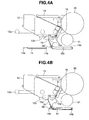
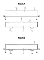
- the arrangement of the ink pan 14 and the holding member 15 will be described below with reference to Figs. 4A, 4B , 5 , 6A, and 6B as well.
- the holding member 15 is formed to have a section having an almost L shape and attached to the lower portion of the ink fountain main body 12 by screws 15a.
- the holding member 15 has a base plate 15c located under the distal end (on the side of the ink fountain roller 30) of the ink fountain main body 12.
- the base plate 15c has almost the same area as that of the ink pan 14.
- the ink pan 14 is placed on the base plate 15c. Hence, the ink pan 14 is supported by the holding member 15 under the distal end of the ink fountain main body 12 to move integrally with the ink fountain main body 12.
- the ink pan 14 is attachable to or detachable from the holding member 15.
- the ink pan 14 is detachably attached to the holding member 15.
- an opening 15d whose size enables to insert or remove the ink pan 14 is formed at the rear end (on the side opposite to the print processing unit 3) of the holding member 15.
- an inner wall 15b serving as a stopper against which a distal end 14b of the ink pan 14 abuts is provided at the distal end (on the side of the print processing unit 3) of the holding member 15, that is, the distal end of the base plate 15c.
- lock levers 56 serving as regulating members for regulating the movement of the rear end of the ink pan 14 is provided at the rear end of the holding member 15, as shown in Fig. 5 .
- Each lock lever 56 is supported to pivot between an open position (the position indicated by the alternate long and two short dashed line in Fig. 5 ) where the opening 15d is opened to enable insertion and removal of the ink pan 14 via the opening 15d and a lock position (the position indicated by the solid line in Fig. 5 ) where the lock lever 56 covers part of the opening 15d to disable insertion and removal of the ink pan 14.
- Pan handles 14a are provided at the rear end of the ink pan 14.
- the ink pan 14 When the ink fountain main body 12 is located at the above-described first position (see Fig. 2C ), the ink pan 14 is disposed under (immediately under) the ink fountain main body 12 and also under (immediately under) the ink roller 31 integrally with the ink fountain main body 12 via the holding member 15. For this reason, the ink pan 14 can receive the ink dropping from the distal end of the ink fountain main body 12 or the ink roller 31.
- the inking device 11 also includes a fixed pan 19 stationarily arranged under (immediately under) the distal end of the ink fountain main body 12, the ink fountain roller 30, and the ink roller 31 and attached to the frames 51 and 52 of the ink supply unit 2.
- the fixed pan 19 is located under the ink pan 14 integrated with the ink fountain main body 12 (at this time, the ink pan 14 is located above the fixed pan 19).
- the base plate 15c of the holding member 15 or the ink pan 14 and the fixed pan 19 are located under (immediately under) the distal end of the ink fountain main body 12 and under (immediately under) the ink fountain roller 30 or the ink roller 31.
- the base plate 15c of the holding member 15 or the ink pan 14 is located under (immediately under) the distal end of the ink fountain main body 12, and the fixed pan 19 is located under (immediately under) the ink fountain roller 30 or the ink roller 31, so that the base plate 15c of the holding member 15 or the ink pan 14 and the fixed pan 19 are disposed continuously in the moving direction of the ink fountain main body 12.
- the base plate 15c of the holding member 15 or the ink pan 14 and the fixed pan 19 cover the space under the inking device 11 in the range from the distal end of the ink fountain main body 12 to the ink fountain roller 30 or the ink roller 31.
- the fixed pans 19 (19-1, 19-2, 19-3, and 19-4) of the inking devices 11-1 to 11-4 in the uppermost to fourth stages are formed into different sizes in accordance with the slide amount of the ink fountain main body 12 to be described later so that the base plate 15c of the holding member 15 or the ink pan 14 and the fixed pan 19 are arranged continuously when the ink fountain main body 12 is located at the second position.
- the inking device 41 in the lowermost stage includes a fixed pan 19-5, like the inking devices 11-1 to 11-4.
- the holding member 15 and the ink pan 14 are not attached to the ink fountain main body 12, unlike the inking devices 11-1 to 11-4.
- the inking device 41 includes a fixed pan 44 capable of receiving the ink dropping from the distal end of the ink fountain main body 12 when the ink fountain main body 12 is located at the second position (see Fig. 3C ) upon non-printing.
- the fixed pan 44 is arranged while partially overlapping the fixed pan 19-5. Hence, the fixed pan 19-5 and the fixed pan 44 are disposed continuously between the first position and the second position of the ink fountain main body 12.
- Each of the inking devices 11-1 to 11-4 and the inking device 41 includes, under the ink fountain main body 12, an illumination 12b that illuminates the lower part of the ink fountain main body 12.
- the illumination 12b is formed from, for example, an LED (Light Emitting Diode).
- the illuminations 12b of the inking devices 11-1 to 11-4 can illuminate the ink fountain main bodies 12 of the inking devices 11-2 to 11-4 and 41 immediately under (in stages under) them and vicinities thereof.
- the inking devices 11-1 to 11-4 in the uppermost to fourth stages fundamentally have a common structure.
- the slide distance (or length) of slide rails 11a of the inking device 11-1 in the uppermost stage is different from the slide distance (or length) of the slide rails 11b of the inking devices 11-2 to 11-4 in the second to fourth stages.
- all the inking devices 11-2 to 11-4 have the same slide distance but may have different slide distances.
- the slide distance (or length) of slide rails 11c of the inking device 41 in the lowermost stage is also different from the slide distances (or lengths) of the slide rails 11a and 11b of the inking devices 11-1 to 11-4 in the uppermost to fourth stages.
- the inking device 11-1 in the uppermost stage corresponds to the chevron cylinder 4 in the uppermost stage out of the five chevron cylinders 4 arranged along the circumferential direction of the intaglio cylinder 8.
- the slide rails 11a of the inking device 11-1 have the longest slide distance.
- the ink fountain main body 12 of the inking device 11-1 is supported by the slide rails 11a having the longest slide distance to slide the longest distance between the first position upon printing and the second position upon non-printing.
- the inking devices 11-2 to 11-4 in the second to fourth stages correspond to the chevron cylinders 4 in the second to fourth stages out of the five chevron cylinders 4 arranged along the circumferential direction of the intaglio cylinder 8.
- the slide rails 11b of the inking devices 11-2 to 11-4 are shorter than the slide rails 11a of the inking device 11-1.
- the ink fountain main bodies 12 of the inking devices 11-2 to 11-4 are supported by the slide rails 11b to slide between the first position upon printing and the second position upon non-printing.
- the chevron cylinders 4 in the second to fourth stages are arranged at positions projecting outward in the circumferential direction from the chevron cylinder 4 in the uppermost stage.
- the ink fountain main body 12 in the uppermost stage, the ink fountain main body 12 in the second stage, the ink fountain main body 12 in the third stage, and the ink fountain main body 12 in the fourth stage are vertically aligned in a straight line at the second position upon non-printing. More exactly speaking, at the second position upon non-printing, the ink fountain main bodies 12 in the stages are aligned vertically not in a complete straight line but in tiers along the circumference of the intaglio cylinder 8.
- the inking device 41 in the lowermost stage corresponds to the chevron cylinder 4 in the lowermost stage arranged at a position projecting outward in the circumferential direction from the chevron cylinder 4 in the uppermost stage.
- the slide rails 11c of the inking device 41 are shorter than the slide rails 11a of the inking device 11-1 and longer than the slide rails 11b of the inking devices 11-2 to 11-4.
- the ink fountain main body 12 of the inking device 41 is supported by the slide rails 11c to slide between the first position upon printing and the second position upon non-printing. 4. Arrangement of Doctor
- the inking device 11 includes a doctor holding member 70.
- the doctor holding member 70 is attached to the ends of the left and right slide rails 11b on the side of the ink fountain roller 30.
- a doctor 71 is set on the doctor holding member 70 using the space formed between the ink fountain main body 12 and the ink fountain roller 30.
- the doctor 71 is attachable to or detachable from the doctor holding member 70. The arrangement of the doctor 71 will be described below with reference to Figs. 8 to 10 in addition to Figs. 7A to 7C .
- the doctor 71 includes a doctor blade 74 and a catch pan 71a.
- the length of the doctor blade 74 is almost equal to the axial length of the outer surface of the ink fountain roller 30.
- the distal end of the doctor blade 74 abuts against the ink fountain roller 30 and cleans it.
- the catch pan 71a has an almost rectangular parallelepiped shape with a length almost equal to the axial length of the outer surface of the ink fountain roller 30.
- the catch pan 71a has an opening at the upper portion, and a space to store a cleaning fluid is formed inside.
- Engaging portions 71b to be used when setting the doctor 71 on the doctor holding member 70 are provided on the left and right sides of the catch pan 71a.
- the engaging portions 71b are fixed to the doctor holding member 70 by bolts (not shown), thereby attaching the doctor 71 to the doctor holding member 70.
- Fig. 9 shows a state before the doctor 71 is set on the doctor holding member 70.
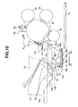
- Fig. 10 shows a state after the doctor 71 is set on the doctor holding member 70.
- an extending portion 73 formed from a plate (for example, thin metal leaf spring) is fixed on the side wall of the catch pan 71a on the side of the ink fountain roller 30 by screws 75 or the like.
- the proximal end of the doctor blade 74 is attached to the distal end of the extending portion 73.
- the doctor blade 74 is made of a resin or plastic.
- the doctor 71 is provided with a cover 77 serving as a second cover extending under the catch pan 71a.
- a support 76 is fixed to the lower side of the side wall of the catch pan 71a on the side of the ink fountain roller 30.
- the cover 77 is attached to the support 76.
- the cover 77 covers the space under the doctor 71, prevents foreign substances from entering from the ink fountain main body 12 to the ink fountain roller 30 and the contact portion between the ink fountain roller 30 and the ink roller 31, and protects the ink fountain roller 30 and the ink roller 31.
- support plates 78 extending under the ink fountain main body 12 are fixed to the frames 51 and 52 of the ink supply unit 2.
- a proximal end 80b of an air cylinder 80 is pivotally supported by each support plate 78 via a shaft 78a.
- One end of an arm 81 is pivotally connected, via a shaft 80d, to a distal end 80c of a rod 80e of the air cylinder 80.
- the other end of the arm 81 is fixed to a pivot shaft 81a pivotally supported by the slide rail 11b.
- the doctor holding member 70 on which the doctor 71 is set is fixed to the pivot shafts 81a.
- a doctor blade abutting and separating unit is formed by the doctor holding member 70, the pivot shafts 81a, the air cylinders 80, the arms 81, and a solenoid valve 65 to be described later.
- an injection nozzle 82 that injects a cleaning fluid made of a solvent to clean the ink fountain roller 30 and the ink rollers 31, 32, and 33 is provided above the ink fountain roller 30.
- the injection nozzle 82 is supported by the frames 51 and 52 while being directed to the contact portion between the ink fountain roller 30 and the ink roller 33. This allows the injection nozzle 82 to inject and spray the cleaning fluid from it toward the portion between the ink fountain roller 30 and the ink roller 33.
- a cleaning fluid supply unit is formed by the injection nozzle 82 and a solenoid valve 64 to be described later.
- a catch pan 86 for receiving the cleaning fluid dropping from the injection nozzle 82 is provided under the injection nozzle 82.
- the inking device 11 includes a cover 83 serving as a first cover at a position above the ink fountain roller 30 and close to the injection nozzle 82 on the side of the ink fountain main body 12.
- the width of the cover 83 is almost equal to the width of the outer surface of the ink fountain roller 30.
- the cover 83 has an almost L-shaped section.
- the cover 83 is made of a resin or the like.
- the cover 83 is attached to the frames 51 and 52.
- the cover 83 covers the space above the ink fountain roller 30 and prevents foreign substances from entering from above the ink fountain roller 30 to the machine of the ink supply apparatus 1.
- the cover 83 is disposed such that its bent distal end is arranged near the distal ends of the holding member 15 and the ink pan 14 (the ends on the side of the ink fountain roller 30) of the inking device in the stage immediately above (for example, the inking device 11-1 in the uppermost stage for the inking device 11-2 in the second stage) when the ink fountain main body 12 of the inking device in the stage immediately above is located at the second position (the position indicated by the alternate long and two short dashed line in Fig. 1 ).
- the cover 83 covers the space between the ink fountain roller 30 in the same stage as the cover 83 and the ink pan or the fixed pan 19 of the inking device in the stage immediately above.
- the cover 83 also prevents foreign substances from entering the machine of the ink supply apparatus 1.
- the lower end of the cover 77 of the doctor 71 is arranged near the outer surface of the ink roller 31 and covers the lower portion of the outer surface of the ink fountain roller 30 and the front surface (the surface on the side of the ink fountain main body 12) of the contact portion between the ink fountain roller 30 and the ink roller 31.
- the cover 77 prevents foreign substances from entering from the lower side of the ink fountain roller 30 to the ink fountain roller 30, in particular, to the contact portion between the ink fountain roller 30 and the ink roller 31.
- the base plate 15c of the holding member 15 or the ink pan 14 and the fixed pan 19 are disposed continuously in the moving direction of the ink fountain main body 12 and cover the lower space in the range from the distal end of the ink fountain main body 12 to the ink fountain roller 30 or the ink roller 31. Foreign substances are thus prevented from entering from the lower side of the inking device 11.
- the foreign entry preventing structures formed by continuously juxtaposing the ink pans 14 and the fixed pans 19 (19-1 to 19-4) doubly and triply prevent foreign substances from entering the machine of the ink supply apparatus 1, in addition to the cover 77 of the doctor 71.
- the covers 83, the covers 77, the holding members 15, the ink pans 14, and the fixed pans 19-3 and 19-4 prevent foreign substances from entering the machine of the ink supply apparatus 1, as in the inking device 11-2 in the second stage.
- the inking device 11-1 in the uppermost stage includes a cover 84 for preventing foreign substances from entering the machine as the first cover in place of the cover 83.
- the cover 84 is disposed at a position above the ink fountain roller 30 and close to the injection nozzle 82 on the side of the ink fountain main body 12 and attached to the frames 51 and 52.
- the width of the cover 84 is almost equal to the width of the outer surface of the ink fountain roller 30.
- the inking device 41 in the lowermost stage includes a cover 85 for preventing foreign substances from entering the machine as the first cover in place of the cover 83.
- the cover 85 is disposed above the ink fountain roller 30, the ink roller 33, and the injection nozzle 82 and attached to the frames 51 and 52.
- the width of the cover 85 is almost equal to the width of the outer surface of the ink fountain roller 30. 6. Arrangement for Controlling Cleaning Processing by Doctor
- the inking device 11 further includes a control device 60, a first sensor 61, a second sensor 62, a motor 63, and the solenoid valves 64 and 65.
- the first sensor 61, the second sensor 62, the motor 63, and the solenoid valves 64 and 65 are electrically connected to the control device 60.
- the first sensor 61 is a first detection device that detects the position of the ink fountain main body 12.
- the first sensor 61 is formed from a sensor such as a limit switch or a proximity switch that detects whether the ink fountain main body 12 is located at the first position upon printing. When the ink fountain main body 12 has left the first position, the first sensor 61 outputs the detection result to the control device 60.
- the second sensor 62 is a second detection device that detects whether the doctor 71 is attached to the doctor holding member 70.
- the second sensor 62 is formed from a sensor such as a limit switch or a proximity switch that detects the presence or absence of attachment of the doctor 71 to the doctor holding member 70, and outputs the detection result to the control device 60.
- the motor 63 is a driving device that rotates the ink fountain roller 30.
- the solenoid valve 64 is a cleaning fluid supply switching unit that turns on and off injection of the cleaning fluid from the injection nozzle 82.
- the solenoid valve 65 is a doctor blade abutting and separating switching unit that brings the doctor blade 74 of the doctor 71 into contact with the ink fountain roller 30 or separates the doctor blade 74 away from the ink fountain roller 30.
- the control device 60 has a function of controlling the solenoid valves 64 and 65 based on the detection results of the first sensor 61 and the second sensor 62 to control the cleaning processing by the doctor 71.
- the control device 60 is formed from a CPU.
- the first sensor 61, the second sensor 62, the motor 63, and the solenoid valves 64 and 65 are provided in each of the inking devices 11-1 to 11-4 and 41 in the uppermost to lowermost stages.
- One control device 60 controls the motors 63 and the solenoid valves 64 and 65 of the inking devices 11-1 to 11-4 and 41 based on the detection results of the sensors 61 and 62 of the inking devices 11-1 to 11-4 and 41.
- the control device 60 may be provided in each of the inking devices 11-1 to 11-4 and 41 and perform distributed processing.
- the storage spaces 13a of the ink fountain main bodies 12 of the five inking devices 11-1 to 11-4 and 41 store inks of different colors.
- the ink fountain roller 30 rotates in the ink supply direction (counterclockwise in Fig. 1 )
- the ink stored in the storage space 13a of the ink fountain main body 12 is adhered to the outer surface of the ink fountain roller 30 via the gap between the blade 16 for gap adjustment and the ink fountain roller 30 and extracted.
- the gap amount between the blade 16 for gap adjustment and the ink fountain roller 30 is adjusted, and the amount of ink extracted from the storage space 13a is adjusted.
- the ink adhered to the ink fountain roller 30 is leveled by the ink roller 31 as the ink fountain roller 30 rotates. After that, the ink is transferred to the chevron cylinder 4 via the ink rollers 32 and 33 and supplied from the chevron cylinder 4 to the outer surface of the intaglio cylinder 8.
- the five color inks are thus supplied from the ink supply unit 2 to the five chevron cylinders 4 of the print processing unit 3, respectively.
- the fixed pan 19 is larger than the ink pan 14.
- the fixed pan 19 has a size large enough to wholly store the ink pan 14 placed on the fixed pan 19.
- the fixed pan 19 is stationarily arranged immediately under the ink pan 14. For this reason, even if the ink dropping from the distal end of the ink fountain main body 12 or the ink dropping from the ink fountain roller 30 or the ink roller 31 overflows from the ink pan 14, the ink that has overflowed is received by the fixed pan 19 that exists under the ink pan 14.
- the printing operation in the inking devices 11-1 to 11-4 in the uppermost to fourth stages has been described above.
- the printing operation in the inking device 41 in the lowermost stage is almost the same.
- the ink pan 14 and the holding member 15 are not attached to the ink fountain main body 12 of the inking device 41, the ink dropping from the distal end of the ink fountain main body 12 or the ink dropping from the ink fountain roller 30 or the ink roller 31 is received by the fixed pan 19-5.
- the operator moves the ink fountain main body 12 to the second position shown in Fig. 3 and attaches the doctor 71 to the doctor holding member 70 in a state in which the print processing unit 3 is at rest, and the motor 63 for rotating the ink fountain roller 30 is at rest.
- the piston rod 80e of the air cylinder 80 is extended in the direction of an arrow PS in Fig. 10 .
- the doctor blade 74 of the doctor 71 attached to the doctor holding member 70 is spaced apart from the outer surface of the ink fountain roller 30.
- the first sensor 61 detects that the ink fountain main body 12 is not located at the first position upon printing.
- the control device 60 controls the motor 63 and the solenoid valves 64 and 65 based on the detection results of the first sensor 61 and the second sensor 62, thereby cleaning the ink fountain roller 30 and the ink rollers 31 to 33.
- control device 60 first drives the motor 63 to rotate the ink fountain roller 30 in the ink supply direction (the direction of an arrow in Fig. 10 ). Then, the control device 60 opens the solenoid valve 64 to inject the cleaning fluid from the injection nozzle 82 to the ink fountain roller 30 and the ink roller 33. The cleaning fluid is thus injected to the ink fountain roller 30 that is rotating.
- the control device 60 retracts the piston rod 80e of the air cylinder 80 in the direction of an arrow PL in Fig. 10 via the solenoid valve 65.
- the pivot shaft 81a thus pivots via the arm 81, and the doctor holding member 70 fixed to the pivot shaft 81a and the doctor 71 attached to the doctor holding member 70 pivot in a direction (the direction of an arrow RR in Fig. 10 ) to move close to the ink fountain roller 30.
- the doctor blade 74 of the doctor 71 is pressed against the outer surface of the ink fountain roller 30.
- the ink on the ink fountain roller 30 dissolves in the cleaning fluid to generate a waste fluid which is scraped off by the doctor blade 74 and stored in the catch pan 71a.
- the ink and the cleaning fluid on the ink rollers 31 to 33 are scraped off by the doctor blade 74 via the ink fountain roller 30 and stored in the catch pan 71a. It is therefore possible to simultaneously clean the ink fountain roller 30 and the ink rollers 31 to 33.
- the operator can clean the ink fountain main body 12 and the like extracted to the second position. More specifically, the operator removes the ink adhered to the ink fountain main body 12, the blade 16 for gap adjustment, and the ink weirs 13 and wipes these members dry by wastes, thereby cleaning them.
- the ink fountain main body 12 is located at the second position shown in Fig. 3 .
- the ink or cleaning fluid dropping from the ink fountain roller 30 or the ink rollers 31 to 33 is received by the fixed pan 19.
- the ink or cleaning fluid dropping from the distal end of the ink fountain main body 12 located at the second position is received by the ink pan 14.
- the ink or cleaning fluid is prevented from dropping to the inking device on the lower side.
- the ink fountain main body 12 When the ink fountain main body 12 is located at the second position, the lower portion of the range for the distal end of the ink fountain main body 12 to the ink fountain roller 30 or the ink roller 31 is continuously covered by the ink pan 14 and the fixed pan 19. For this reason, the ink or cleaning fluid is properly prevented for dropping to the inking device 11 on the lower side.
- the control device 60 When the cleaning operation has been done for a predetermined time, the control device 60 first closes the solenoid valve 64 to stop cleaning fluid injection from the injection nozzle 82. After the elapse of a predetermined time from the stop of cleaning fluid injection, the doctor blade 74 scrapes off the cleaning fluid on the outer surfaces of the ink fountain roller 30 and the ink rollers 31 to 33. At this timing, the control device 60 extends the piston rod 80e of the air cylinder 80 in the direction of the arrow PS in Fig. 10 via the solenoid valve 65.
- the pivot shaft 81a thus pivots via the arm 81, and the doctor holding member 70 fixed to the pivot shaft 81a and the doctor 71 attached to the doctor holding member 70 pivot in a direction (the direction of an arrow RL in Fig. 10 ) to move away from the ink fountain roller 30.
- the doctor blade 74 of the doctor 71 is separated from the outer surface of the ink fountain roller 30.
- the control device 60 stops driving the motor 63 to stop the rotation of the ink fountain roller 30.
- the operator locates the lock lever 56 at the open position to open the opening 15d, grips the pan handles 14a, removes the ink pan 14 from the opening 15d, and cleans the ink pan 14 outside the printing press.
- the operator inserts the ink pan 14 from the opening 15d until the distal end 14b abuts against the inner wall 15b of the base plate 15c to place the ink pan 14 on the base plate 15c, and locates the lock lever 56 at the lock position.
- the lock lever 56 is located at the lock position, the ink pan 14 is prevented from exiting from the opening 15d.
- the ink pan 14 can be removed and detached from the holding member 15 even during the cleaning operation or print processing. For this reason, the ink pan 14 can be cleaned while continuing cleaning the ink fountain main body 12 without stopping print processing. It is therefore possible to perform print processing without lowering the capacity utilization of the printing press.
- the cleaning operation in the inking devices 11-1 to 11-4 in the uppermost to fourth stages has been described above.
- the ink or cleaning fluid dropping from the ink fountain roller 30 or the ink rollers 31 to 33 is received by the fixed pan 19-5.
- the ink or cleaning fluid dropping from the distal end of the ink fountain main body 12 located at the second position is received by the fixed pan 44.
- the ink fountain main body 12 of an arbitrary one of the inking devices 11-1 to 11-4 and 41 in the uppermost to lowermost stages can be extracted and cleaned, or all ink fountain main bodies 12 can be extracted and cleaned.
- the ink fountain rollers 30 of the inking devices 11-1 to 11-4 and 41 can be driven in the state in which all ink fountain main bodies 12 are located at the second position. It is therefore possible to simultaneously perform automatic cleaning of the ink fountain rollers 30 and the ink rollers 31 to 33 and cleaning of the ink fountain main bodies 12 by the operator. As a result, the cleaning time is shortened to improve the productivity, and the load on the operator is largely reduced.
- the slide distance changes between the inking device 11-1 in the uppermost stage, the inking devices 11-2 to 11-4 in the second to fourth stages, and the inking device 41 in the lowermost stage.
- the ink fountain main bodies 12 of the inking devices 11-1 to 11-4 and 41 in the respective stages can be arranged vertically almost in a straight line at the second position upon non-printing. This allows the operator to easily execute the cleaning operation of the ink fountain main bodies 12 in the respective stages.
- the ink fountain main bodies 12 of the inking devices 11-1 to 11-4 and 41 in the respective stages slidably move on the slide rails 11a, 11b, and 11c of the inking devices 11-1 to 11-4 and 41 in the respective stages, the ink fountain main bodies 12 can be located at positions where a sufficient space is ensured in the vertical direction. This allows the operator to efficiently clean the ink fountain main body 12 with minimum physical load.
- the illuminations 12b are provided under the ink fountain main bodies 12 of the inking devices 11-1 to 11-4 in the uppermost to fourth stages.
- the illuminations 12b illuminate the ink fountain main bodies 12 of on the lower side and vicinities thereof, the ink fountain main body 12 on the lower side can be cleaned under a bright environment.
- the doctor 71 configured to clean the ink fountain roller 30 can be set in the space between the ink fountain main body 12 and the ink fountain roller 30 while bringing the doctor blade 74 and the ink fountain roller 30 into contact with each other. It is therefore possible to effectively use the space between the ink fountain main body 12 and the ink fountain roller 30, which is formed when the ink fountain main body 12 is extracted from the first position to the second position. It is also possible to efficiently clean the ink fountain roller 30 without physical load on the operator.
- the ink fountain main body 12 can be extracted from the far side in the machine to the near side by sliding the ink fountain main body 12 from the first position to the second position, the ink fountain main body 12 can be cleaned without physical load on the operator.
- the cleaning fluid used for cleaning by the doctor blade 74 is received by the catch pan 71a integrated with the doctor blade 74.
- the catch pan 71a need not always be integrated with the doctor blade 74.
- the cleaning fluid may be received by the catch pan 71a provided independently of the doctor blade 74.
- the doctor blade abutting and separating unit may be configured to bring only the doctor blade 74 into contact with the ink fountain roller 30 or separate them from each other.
- a sensor such as a limit switch or a proximity switch is usable as the first sensor 61.
- the present invention is not limited to this.
- the first sensor 61 detects that the ink fountain main body 12 is located at the first position.
- the first sensor 61 may be a sensor for detecting that the ink fountain main body 12 is located at the second position. In this case, when the first sensor 61 detects that the ink fountain main body 12 is located at the second position, and the second sensor 62 detects that the doctor 71 is attached to the doctor holding member 70, the control device 60 controls to start the cleaning operation for the outer surface of the ink fountain roller 30.
- a sensor such as a limit switch or a proximity switch is usable as the second sensor 62.
- the present invention is not limited to this.
- a device that optically detects the position using a photodetetor or the like is also usable as the second sensor 62.
- the inking devices 11-1 to 11-4 and 41 are applied to the intaglio printing press.
- the present invention is not limited to this.
- the inking devices 11-1 to 11-4 and 41 are applicable to printing presses of various other types.
Landscapes
- Engineering & Computer Science (AREA)
- Mechanical Engineering (AREA)
- Inking, Control Or Cleaning Of Printing Machines (AREA)
Abstract
Description
- The present invention relates to an ink supply apparatus of a printing press.
- The ink supply apparatus of a multicolor printing press includes an inking device for supplying an ink for each ink color. Japanese Patent Laid-Open No.
2001-328240 - The ink fountain device is swingably supported by a pivot. A rigid ball assembled to a lock handle selectively engages with three engaging grooves formed in each of the inner surfaces of the left and right frames, thereby switching the position of the ink fountain device between the fixed position, the throw-off position, and the intermediate position.
- However, in an arrangement in which the inking devices are arranged at a deep position in the machine or an arrangement in which the plurality of inking devices are arranged vertically along the outer surface of an intaglio cylinder or a collecting blanket cylinder as in, for example, the ink supply apparatus of an intaglio printing press, cleaning the ink or the ink fountain roller is time-consuming, and physical load on the operator is heavy.
- The present invention has been made to solve the above-described problems, and has as its object to provide an ink supply apparatus of a printing press which can efficiently clean an ink and an ink fountain roller with minimum physical load on an operator.
- In order to achieve the above-described object, according to the present invention, there is provided an ink supply apparatus of a printing press, comprising at least one inking device including an ink fountain roller that is rotatably supported, an ink fountain main body that forms a space to store an ink together with an outer surface of the ink fountain roller, a guide member that slidably supports the ink fountain main body and guides the ink fountain main body between a first position where the space is formed and a second position spaced apart from the ink fountain roller than the first position and a doctor holding member to which a doctor including a blade is attached between the ink fountain main body and the ink fountain roller when the ink fountain main body is located at the second position, the blade abutting against the ink fountain roller and cleaning the ink fountain roller.
-
-
Fig. 1 is a side view showing the overall arrangement of an ink supply apparatus; -
Figs. 2A to 2C are views showing the state of an inking device when an ink fountain main body is located at a first position in which, in particular,Fig. 2A is a plan view,Fig. 2B is a rear view, andFig. 2C is a side view; -
Figs. 3A to 3C are views showing the state of the inking device when the ink fountain main body is located at a second position in which, in particular,Fig. 3A is a plan view,Fig. 3B is a rear view, andFig. 3C is a side view; -
Fig. 4A is a side view showing a state before an ink pan is set in a holding member; -
Fig. 4B is a side view showing a state in which the ink pan is set in the holding member; -
Fig. 5 is a rear view showing a state in which the ink pan is set in the holding member; -
Fig. 6A is a plan view showing a state before the ink pan is set in the holding member; -
Fig. 6B is a plan view showing a state in which the ink pan is set in the holding member; -
Figs. 7A to 7C are views showing a state in which a doctor is set in the inking device in which, in particular,Fig. 7A is a plan view,Fig. 7B is a rear view, andFig. 7C is a side view; -
Fig. 8 is a sectional view showing the arrangement of the doctor set in the inking device; -
Fig. 9 is a side view showing a state before the doctor is set in the inking device; -
Fig. 10 is a side view showing a state after the doctor is set in the inking device; and -
Fig. 11 is a block diagram showing the circuit arrangement of the ink supply apparatus. - An embodiment of the present invention will now be described in detail with reference to the accompanying drawings. In the embodiment, a case will be explained in which the present invention is applied to the ink supply apparatus of an intaglio printing press in which a plurality of inking devices are arranged vertically along the outer surface of an intaglio cylinder.
-
Fig. 1 shows the overall arrangement of an ink supply apparatus of an intaglio printing press according to an embodiment of the present invention. Anink supply apparatus 1 includes anink supply unit 2 serving as an ink supply system, and aprint processing unit 3 that performs print processing using ink supplied from theink supply unit 2. - The
print processing unit 3 includes anintaglio cylinder 8, and five chevron cylinders (blanket cylinders) 4 arranged in contact with the outer surface of theintaglio cylinder 8. The fivechevron cylinders 4 are arranged while being spaced apart from each other at a predetermined interval vertically along the circumferential direction of theintaglio cylinder 8. - The
ink supply unit 2 includes five inking devices corresponding to the fivechevron cylinders 4, respectively. The five inking devices are arranged while being spaced apart from each other at a predetermined interval vertically. The inking devices in the uppermost stage (first stage), the second stage, the third stage, and the fourth stage will be referred to as inking devices 11-1, 11-2, 11-3, and 11-4, and the inking device in the lowermost stage (fifth stage) will be referred to as aninking device 41. - The inking devices 11-1 to 11-4 fundamentally have a common structure. Hence, the arrangement of the inking device 11-2 in the second stage will be explained as the representative of the inking devices 11-1 to 11-4. The arrangement of the inking
device 41 in the lowermost stage will be described then. The inking device 11-2 will sometimes be referred to as the inkingdevice 11 hereinafter. - As shown in
Figs. 2A to 2C andFigs. 3A to 3C , theinking device 11 includes anink fountain roller 30, an ink fountainmain body 12, and threeink rollers ink fountain roller 30 is rotatably supported by left andright frames main body 12 is supported to be movable close to or away from theink fountain roller 30 and forms aspace 13a to store an ink together with the outer surface of theink fountain roller 30. The twoink rollers ink fountain roller 30 and thechevron cylinder 4. Theink roller 31 under theink fountain roller 30 contacts theink fountain roller 30. - The inking
device 11 also includes twoslide rails 11b provided on the left andright frames ink fountain roller 30. The slide rails 11b slidably support the ink fountainmain body 12 on its left and right sides, and guide the ink fountainmain body 12 between the position (to be referred to as a "first position" hereinafter) shown inFig. 2C where the ink fountainmain body 12 comes close to or contacts theink fountain roller 30 and the position (to be referred to as a "second position" hereinafter) shown inFig. 3C spaced apart from theink fountain roller 30 than the first position. Upon printing, the ink fountainmain body 12 is located at the first position to form thestorage space 13a, and the ink stored in thestorage space 13a is extracted by theink fountain roller 30. Upon non-printing, the ink fountainmain body 12 is located at the second position, and a wide space is formed between the ink fountainmain body 12 and theink fountain roller 30. - A total of eighth cam followers (rollers) 18 are provided, of which four cam followers are provided on each of the left and right sides of the ink fountain
main body 12. The eightcam followers 18 engage with the left and right slide rails 11b. More specifically, a pair ofcam followers 18 are arranged at an angle of 90°. Onecam follower 18 abuts against the upper surface of theslide rail 11b, and theother cam follower 18 abuts against the side surface of theslide rail 11b. Two pairs ofcam followers 18 are disposed on each side. - On the upper surface of the ink fountain
main body 12 serving as the bottom of thespace 13a, a pair ofink weirs 13 are vertically arranged at two ends in a direction parallel to the axial direction of theink fountain roller 30. Thestorage space 13a whose section perpendicular to the axial direction has an almost triangular shape is formed by the upper surface of the ink fountainmain body 12, the outer surface of theink fountain roller 30, and the pair ofink weirs 13. - A
blade 16 for gap adjustment is attached to the distal end of the upper surface of the ink fountainmain body 12 while facing the outer surface of theink fountain roller 30. Theblade 16 is movably supported to adjust the gap amount between the ink fountainmain body 12 and the outer surface of theink fountain roller 30. - Note that an ink fountain is formed by the ink fountain
main body 12, theink weirs 13, theblade 16 for gap adjustment, and theink fountain roller 30. - The inking
device 11 further includes anink pan 14, and a holdingmember 15 serving as an ink pan holding portion for holding theink pan 14. The arrangement of theink pan 14 and the holdingmember 15 will be described below with reference toFigs. 4A, 4B ,5 ,6A, and 6B as well. - As shown in
Fig. 4A , the holdingmember 15 is formed to have a section having an almost L shape and attached to the lower portion of the ink fountainmain body 12 byscrews 15a. The holdingmember 15 has abase plate 15c located under the distal end (on the side of the ink fountain roller 30) of the ink fountainmain body 12. Thebase plate 15c has almost the same area as that of theink pan 14. Theink pan 14 is placed on thebase plate 15c. Hence, theink pan 14 is supported by the holdingmember 15 under the distal end of the ink fountainmain body 12 to move integrally with the ink fountainmain body 12. - The
ink pan 14 is attachable to or detachable from the holdingmember 15. Theink pan 14 is detachably attached to the holdingmember 15. As shown inFig. 5 , anopening 15d whose size enables to insert or remove theink pan 14 is formed at the rear end (on the side opposite to the print processing unit 3) of the holdingmember 15. - As shown in
Fig. 4A , aninner wall 15b serving as a stopper against which adistal end 14b of theink pan 14 abuts is provided at the distal end (on the side of the print processing unit 3) of the holdingmember 15, that is, the distal end of thebase plate 15c. - To prevent the
ink pan 14 from exiting from theopening 15d, lock levers 56 serving as regulating members for regulating the movement of the rear end of theink pan 14 is provided at the rear end of the holdingmember 15, as shown inFig. 5 . Eachlock lever 56 is supported to pivot between an open position (the position indicated by the alternate long and two short dashed line inFig. 5 ) where theopening 15d is opened to enable insertion and removal of theink pan 14 via theopening 15d and a lock position (the position indicated by the solid line inFig. 5 ) where thelock lever 56 covers part of theopening 15d to disable insertion and removal of theink pan 14. - Pan handles 14a are provided at the rear end of the
ink pan 14. - When the ink fountain
main body 12 is located at the above-described first position (seeFig. 2C ), theink pan 14 is disposed under (immediately under) the ink fountainmain body 12 and also under (immediately under) theink roller 31 integrally with the ink fountainmain body 12 via the holdingmember 15. For this reason, theink pan 14 can receive the ink dropping from the distal end of the ink fountainmain body 12 or theink roller 31. - As shown in
Figs. 2C and3C , the inkingdevice 11 also includes a fixedpan 19 stationarily arranged under (immediately under) the distal end of the ink fountainmain body 12, theink fountain roller 30, and theink roller 31 and attached to theframes ink supply unit 2. When the ink fountainmain body 12 is located at the first position (seeFig. 2C ) upon printing, the fixedpan 19 is located under theink pan 14 integrated with the ink fountain main body 12 (at this time, theink pan 14 is located above the fixed pan 19). - Hence, when the ink fountain
main body 12 is located at the first position upon printing, thebase plate 15c of the holdingmember 15 or theink pan 14 and the fixedpan 19 are located under (immediately under) the distal end of the ink fountainmain body 12 and under (immediately under) theink fountain roller 30 or theink roller 31. - On the other hand, when the ink fountain
main body 12 is located at the second position (seeFig. 3C ) upon non-printing, thebase plate 15c of the holdingmember 15 or theink pan 14 is located under (immediately under) the distal end of the ink fountainmain body 12, and the fixedpan 19 is located under (immediately under) theink fountain roller 30 or theink roller 31, so that thebase plate 15c of the holdingmember 15 or theink pan 14 and the fixedpan 19 are disposed continuously in the moving direction of the ink fountainmain body 12. Hence, thebase plate 15c of the holdingmember 15 or theink pan 14 and the fixedpan 19 cover the space under the inkingdevice 11 in the range from the distal end of the ink fountainmain body 12 to theink fountain roller 30 or theink roller 31. - As shown in
Fig. 1 , the fixed pans 19 (19-1, 19-2, 19-3, and 19-4) of the inking devices 11-1 to 11-4 in the uppermost to fourth stages are formed into different sizes in accordance with the slide amount of the ink fountainmain body 12 to be described later so that thebase plate 15c of the holdingmember 15 or theink pan 14 and the fixedpan 19 are arranged continuously when the ink fountainmain body 12 is located at the second position. - The inking
device 41 in the lowermost stage includes a fixed pan 19-5, like the inking devices 11-1 to 11-4. However, the holdingmember 15 and theink pan 14 are not attached to the ink fountainmain body 12, unlike the inking devices 11-1 to 11-4. Instead, the inkingdevice 41 includes a fixedpan 44 capable of receiving the ink dropping from the distal end of the ink fountainmain body 12 when the ink fountainmain body 12 is located at the second position (seeFig. 3C ) upon non-printing. The fixedpan 44 is arranged while partially overlapping the fixed pan 19-5. Hence, the fixed pan 19-5 and the fixedpan 44 are disposed continuously between the first position and the second position of the ink fountainmain body 12. - Each of the inking devices 11-1 to 11-4 and the
inking device 41 includes, under the ink fountainmain body 12, anillumination 12b that illuminates the lower part of the ink fountainmain body 12. Theillumination 12b is formed from, for example, an LED (Light Emitting Diode). Theilluminations 12b of the inking devices 11-1 to 11-4 can illuminate the ink fountainmain bodies 12 of the inking devices 11-2 to 11-4 and 41 immediately under (in stages under) them and vicinities thereof. - As described above, in the
ink supply unit 2, the inking devices 11-1 to 11-4 in the uppermost to fourth stages fundamentally have a common structure. However, as shown inFig. 1 , the slide distance (or length) ofslide rails 11a of the inking device 11-1 in the uppermost stage is different from the slide distance (or length) of the slide rails 11b of the inking devices 11-2 to 11-4 in the second to fourth stages. In this embodiment, all the inking devices 11-2 to 11-4 have the same slide distance but may have different slide distances. - The slide distance (or length) of
slide rails 11c of theinking device 41 in the lowermost stage is also different from the slide distances (or lengths) of the slide rails 11a and 11b of the inking devices 11-1 to 11-4 in the uppermost to fourth stages. - This will be described in more detail. As shown in
Fig. 1 , the inking device 11-1 in the uppermost stage corresponds to thechevron cylinder 4 in the uppermost stage out of the fivechevron cylinders 4 arranged along the circumferential direction of theintaglio cylinder 8. The slide rails 11a of the inking device 11-1 have the longest slide distance. Hence, the ink fountainmain body 12 of the inking device 11-1 is supported by the slide rails 11a having the longest slide distance to slide the longest distance between the first position upon printing and the second position upon non-printing. - The inking devices 11-2 to 11-4 in the second to fourth stages correspond to the
chevron cylinders 4 in the second to fourth stages out of the fivechevron cylinders 4 arranged along the circumferential direction of theintaglio cylinder 8. The slide rails 11b of the inking devices 11-2 to 11-4 are shorter than the slide rails 11a of the inking device 11-1. The ink fountainmain bodies 12 of the inking devices 11-2 to 11-4 are supported by the slide rails 11b to slide between the first position upon printing and the second position upon non-printing. - As shown in
Fig. 1 , thechevron cylinders 4 in the second to fourth stages are arranged at positions projecting outward in the circumferential direction from thechevron cylinder 4 in the uppermost stage. Hence, when the slide distance of the slide rails 11b is shorter than that of theslide rails 11a, the ink fountainmain body 12 in the uppermost stage, the ink fountainmain body 12 in the second stage, the ink fountainmain body 12 in the third stage, and the ink fountainmain body 12 in the fourth stage are vertically aligned in a straight line at the second position upon non-printing. More exactly speaking, at the second position upon non-printing, the ink fountainmain bodies 12 in the stages are aligned vertically not in a complete straight line but in tiers along the circumference of theintaglio cylinder 8. - The inking
device 41 in the lowermost stage corresponds to thechevron cylinder 4 in the lowermost stage arranged at a position projecting outward in the circumferential direction from thechevron cylinder 4 in the uppermost stage. The slide rails 11c of theinking device 41 are shorter than the slide rails 11a of the inking device 11-1 and longer than the slide rails 11b of the inking devices 11-2 to 11-4. The ink fountainmain body 12 of theinking device 41 is supported by the slide rails 11c to slide between the first position upon printing and the second position upon non-printing. 4. Arrangement of Doctor - The description of the arrangement of the inking device 11-2 (11) in the second stage of the
ink supply unit 2 will be continued. As shown inFigs. 2A, 2C ,3A, and 3C , the inkingdevice 11 includes adoctor holding member 70. Thedoctor holding member 70 is attached to the ends of the left and right slide rails 11b on the side of theink fountain roller 30. - As shown in
Figs. 7A to 7C , when the ink fountainmain body 12 is located at the second position upon non-printing along the slide rails 11b, adoctor 71 is set on thedoctor holding member 70 using the space formed between the ink fountainmain body 12 and theink fountain roller 30. Thedoctor 71 is attachable to or detachable from thedoctor holding member 70. The arrangement of thedoctor 71 will be described below with reference toFigs. 8 to 10 in addition toFigs. 7A to 7C . - As shown in
Figs. 7A and8 , thedoctor 71 includes adoctor blade 74 and acatch pan 71a. The length of thedoctor blade 74 is almost equal to the axial length of the outer surface of theink fountain roller 30. The distal end of thedoctor blade 74 abuts against theink fountain roller 30 and cleans it. Thecatch pan 71a has an almost rectangular parallelepiped shape with a length almost equal to the axial length of the outer surface of theink fountain roller 30. Thecatch pan 71a has an opening at the upper portion, and a space to store a cleaning fluid is formed inside. - Engaging
portions 71b to be used when setting thedoctor 71 on thedoctor holding member 70 are provided on the left and right sides of thecatch pan 71a. The engagingportions 71b are fixed to thedoctor holding member 70 by bolts (not shown), thereby attaching thedoctor 71 to thedoctor holding member 70.Fig. 9 shows a state before thedoctor 71 is set on thedoctor holding member 70.Fig. 10 shows a state after thedoctor 71 is set on thedoctor holding member 70. - As shown in
Fig. 8 , an extendingportion 73 formed from a plate (for example, thin metal leaf spring) is fixed on the side wall of thecatch pan 71a on the side of theink fountain roller 30 byscrews 75 or the like. The proximal end of thedoctor blade 74 is attached to the distal end of the extendingportion 73. Thedoctor blade 74 is made of a resin or plastic. - The
doctor 71 is provided with acover 77 serving as a second cover extending under thecatch pan 71a. Asupport 76 is fixed to the lower side of the side wall of thecatch pan 71a on the side of theink fountain roller 30. Thecover 77 is attached to thesupport 76. Thecover 77 covers the space under thedoctor 71, prevents foreign substances from entering from the ink fountainmain body 12 to theink fountain roller 30 and the contact portion between theink fountain roller 30 and theink roller 31, and protects theink fountain roller 30 and theink roller 31. - Note that as a plurality of holes each having a rectangular shape are formed in the surface of the
cover 77, as shown inFig. 7B . The operator can visually confirm the state of theink fountain roller 30 from outside of thecover 77 through the plurality of holes. - As shown in
Figs. 7A ,9 , and10 ,support plates 78 extending under the ink fountainmain body 12 are fixed to theframes ink supply unit 2. Aproximal end 80b of anair cylinder 80 is pivotally supported by eachsupport plate 78 via ashaft 78a. One end of anarm 81 is pivotally connected, via ashaft 80d, to adistal end 80c of arod 80e of theair cylinder 80. The other end of thearm 81 is fixed to apivot shaft 81a pivotally supported by theslide rail 11b. Thedoctor holding member 70 on which thedoctor 71 is set is fixed to thepivot shafts 81a. A doctor blade abutting and separating unit is formed by thedoctor holding member 70, thepivot shafts 81a, theair cylinders 80, thearms 81, and asolenoid valve 65 to be described later. - In the
inking device 11, aninjection nozzle 82 that injects a cleaning fluid made of a solvent to clean theink fountain roller 30 and theink rollers ink fountain roller 30. Theinjection nozzle 82 is supported by theframes ink fountain roller 30 and theink roller 33. This allows theinjection nozzle 82 to inject and spray the cleaning fluid from it toward the portion between theink fountain roller 30 and theink roller 33. A cleaning fluid supply unit is formed by theinjection nozzle 82 and asolenoid valve 64 to be described later. Acatch pan 86 for receiving the cleaning fluid dropping from theinjection nozzle 82 is provided under theinjection nozzle 82. - An entry preventing structure that prevents foreign substances from entering the machine of the ink supply apparatus 1 (or printing press) when the ink fountain
main bodies 12 in the inking devices 11-1 to 11-4 and 41 of theink supply unit 2 are located at the second position upon non-printing will be described by exemplifying the inking device 11-2 (11) in the second stage. - As shown in
Figs. 9 and10 , the inkingdevice 11 includes acover 83 serving as a first cover at a position above theink fountain roller 30 and close to theinjection nozzle 82 on the side of the ink fountainmain body 12. The width of thecover 83 is almost equal to the width of the outer surface of theink fountain roller 30. Thecover 83 has an almost L-shaped section. Thecover 83 is made of a resin or the like. Thecover 83 is attached to theframes cover 83 covers the space above theink fountain roller 30 and prevents foreign substances from entering from above theink fountain roller 30 to the machine of theink supply apparatus 1. - The
cover 83 is disposed such that its bent distal end is arranged near the distal ends of the holdingmember 15 and the ink pan 14 (the ends on the side of the ink fountain roller 30) of the inking device in the stage immediately above (for example, the inking device 11-1 in the uppermost stage for the inking device 11-2 in the second stage) when the ink fountainmain body 12 of the inking device in the stage immediately above is located at the second position (the position indicated by the alternate long and two short dashed line inFig. 1 ). For this reason, thecover 83 covers the space between theink fountain roller 30 in the same stage as thecover 83 and the ink pan or the fixedpan 19 of the inking device in the stage immediately above. Hence, thecover 83 also prevents foreign substances from entering the machine of theink supply apparatus 1. - When the
doctor 71 is attached to thedoctor holding member 70, the lower end of thecover 77 of thedoctor 71 is arranged near the outer surface of theink roller 31 and covers the lower portion of the outer surface of theink fountain roller 30 and the front surface (the surface on the side of the ink fountain main body 12) of the contact portion between theink fountain roller 30 and theink roller 31. Thecover 77 prevents foreign substances from entering from the lower side of theink fountain roller 30 to theink fountain roller 30, in particular, to the contact portion between theink fountain roller 30 and theink roller 31. - In addition, when the ink fountain
main body 12 is located at the second position upon non-printing, thebase plate 15c of the holdingmember 15 or theink pan 14 and the fixedpan 19 are disposed continuously in the moving direction of the ink fountainmain body 12 and cover the lower space in the range from the distal end of the ink fountainmain body 12 to theink fountain roller 30 or theink roller 31. Foreign substances are thus prevented from entering from the lower side of theinking device 11. - Especially in the inking device 11-1 in the uppermost stage to the inking device 11-4 in the fourth stage, the foreign entry preventing structures formed by continuously juxtaposing the ink pans 14 and the fixed pans 19 (19-1 to 19-4) doubly and triply prevent foreign substances from entering the machine of the
ink supply apparatus 1, in addition to thecover 77 of thedoctor 71. - In the inking device 11-3 in the third stage and the inking device 11-4 in the fourth stage as well, the
covers 83, thecovers 77, the holdingmembers 15, the ink pans 14, and the fixed pans 19-3 and 19-4 prevent foreign substances from entering the machine of theink supply apparatus 1, as in the inking device 11-2 in the second stage. - As shown in
Fig. 1 , the inking device 11-1 in the uppermost stage includes acover 84 for preventing foreign substances from entering the machine as the first cover in place of thecover 83. Thecover 84 is disposed at a position above theink fountain roller 30 and close to theinjection nozzle 82 on the side of the ink fountainmain body 12 and attached to theframes cover 84 is almost equal to the width of the outer surface of theink fountain roller 30. - The inking
device 41 in the lowermost stage includes acover 85 for preventing foreign substances from entering the machine as the first cover in place of thecover 83. Thecover 85 is disposed above theink fountain roller 30, theink roller 33, and theinjection nozzle 82 and attached to theframes cover 85 is almost equal to the width of the outer surface of theink fountain roller 30. 6. Arrangement for Controlling Cleaning Processing by Doctor - As shown in
Fig. 11 , the inkingdevice 11 further includes acontrol device 60, afirst sensor 61, asecond sensor 62, amotor 63, and thesolenoid valves first sensor 61, thesecond sensor 62, themotor 63, and thesolenoid valves control device 60. - The
first sensor 61 is a first detection device that detects the position of the ink fountainmain body 12. Thefirst sensor 61 is formed from a sensor such as a limit switch or a proximity switch that detects whether the ink fountainmain body 12 is located at the first position upon printing. When the ink fountainmain body 12 has left the first position, thefirst sensor 61 outputs the detection result to thecontrol device 60. - The
second sensor 62 is a second detection device that detects whether thedoctor 71 is attached to thedoctor holding member 70. Thesecond sensor 62 is formed from a sensor such as a limit switch or a proximity switch that detects the presence or absence of attachment of thedoctor 71 to thedoctor holding member 70, and outputs the detection result to thecontrol device 60. - The
motor 63 is a driving device that rotates theink fountain roller 30. Thesolenoid valve 64 is a cleaning fluid supply switching unit that turns on and off injection of the cleaning fluid from theinjection nozzle 82. Thesolenoid valve 65 is a doctor blade abutting and separating switching unit that brings thedoctor blade 74 of thedoctor 71 into contact with theink fountain roller 30 or separates thedoctor blade 74 away from theink fountain roller 30. - The
control device 60 has a function of controlling thesolenoid valves first sensor 61 and thesecond sensor 62 to control the cleaning processing by thedoctor 71. Thecontrol device 60 is formed from a CPU. - The
first sensor 61, thesecond sensor 62, themotor 63, and thesolenoid valves control device 60 controls themotors 63 and thesolenoid valves sensors control device 60 may be provided in each of the inking devices 11-1 to 11-4 and 41 and perform distributed processing. - The operation of the
ink supply apparatus 1 having the above-described arrangement will be described divisionally concerning the printing operation and the cleaning operation. - The
storage spaces 13a of the ink fountainmain bodies 12 of the five inking devices 11-1 to 11-4 and 41 store inks of different colors. When theink fountain roller 30 rotates in the ink supply direction (counterclockwise inFig. 1 ), the ink stored in thestorage space 13a of the ink fountainmain body 12 is adhered to the outer surface of theink fountain roller 30 via the gap between theblade 16 for gap adjustment and theink fountain roller 30 and extracted. - When the position of the
blade 16 for gap adjustment is adjusted, the gap amount between theblade 16 for gap adjustment and theink fountain roller 30 is adjusted, and the amount of ink extracted from thestorage space 13a is adjusted. - The ink adhered to the
ink fountain roller 30 is leveled by theink roller 31 as theink fountain roller 30 rotates. After that, the ink is transferred to thechevron cylinder 4 via theink rollers chevron cylinder 4 to the outer surface of theintaglio cylinder 8. The five color inks are thus supplied from theink supply unit 2 to the fivechevron cylinders 4 of theprint processing unit 3, respectively. - An ink dropping from the distal end of the ink fountain
main body 12 or theink fountain roller 30 or theink roller 31 during the printing operation is received by theink pan 14 or the fixedpan 19. Hence, the ink is prevented from dropping the inking device on the lower side. - The fixed
pan 19 is larger than theink pan 14. The fixedpan 19 has a size large enough to wholly store theink pan 14 placed on the fixedpan 19. The fixedpan 19 is stationarily arranged immediately under theink pan 14. For this reason, even if the ink dropping from the distal end of the ink fountainmain body 12 or the ink dropping from theink fountain roller 30 or theink roller 31 overflows from theink pan 14, the ink that has overflowed is received by the fixedpan 19 that exists under theink pan 14. - The printing operation in the inking devices 11-1 to 11-4 in the uppermost to fourth stages has been described above. The printing operation in the
inking device 41 in the lowermost stage is almost the same. However, since theink pan 14 and the holdingmember 15 are not attached to the ink fountainmain body 12 of theinking device 41, the ink dropping from the distal end of the ink fountainmain body 12 or the ink dropping from theink fountain roller 30 or theink roller 31 is received by the fixed pan 19-5. - To clean the inking
device 11 after the printing operation, the operator moves the ink fountainmain body 12 to the second position shown inFig. 3 and attaches thedoctor 71 to thedoctor holding member 70 in a state in which theprint processing unit 3 is at rest, and themotor 63 for rotating theink fountain roller 30 is at rest. - Before the cleaning operation, the
piston rod 80e of theair cylinder 80 is extended in the direction of an arrow PS inFig. 10 . For this reason, thedoctor blade 74 of thedoctor 71 attached to thedoctor holding member 70 is spaced apart from the outer surface of theink fountain roller 30. - When the ink fountain
main body 12 has moved to the second position, thefirst sensor 61 detects that the ink fountainmain body 12 is not located at the first position upon printing. When thesecond sensor 62 detects that thedoctor 71 is attached to thedoctor holding member 70, thecontrol device 60 controls themotor 63 and thesolenoid valves first sensor 61 and thesecond sensor 62, thereby cleaning theink fountain roller 30 and theink rollers 31 to 33. - More specifically, the
control device 60 first drives themotor 63 to rotate theink fountain roller 30 in the ink supply direction (the direction of an arrow inFig. 10 ). Then, thecontrol device 60 opens thesolenoid valve 64 to inject the cleaning fluid from theinjection nozzle 82 to theink fountain roller 30 and theink roller 33. The cleaning fluid is thus injected to theink fountain roller 30 that is rotating. - When the cleaning fluid is supplied to the outer surface of the
ink fountain roller 30, thecontrol device 60 retracts thepiston rod 80e of theair cylinder 80 in the direction of an arrow PL inFig. 10 via thesolenoid valve 65. Thepivot shaft 81a thus pivots via thearm 81, and thedoctor holding member 70 fixed to thepivot shaft 81a and thedoctor 71 attached to thedoctor holding member 70 pivot in a direction (the direction of an arrow RR inFig. 10 ) to move close to theink fountain roller 30. Thedoctor blade 74 of thedoctor 71 is pressed against the outer surface of theink fountain roller 30. - The ink on the
ink fountain roller 30 dissolves in the cleaning fluid to generate a waste fluid which is scraped off by thedoctor blade 74 and stored in thecatch pan 71a. The ink and the cleaning fluid on theink rollers 31 to 33 are scraped off by thedoctor blade 74 via theink fountain roller 30 and stored in thecatch pan 71a. It is therefore possible to simultaneously clean theink fountain roller 30 and theink rollers 31 to 33. - During the cleaning, the operator can clean the ink fountain
main body 12 and the like extracted to the second position. More specifically, the operator removes the ink adhered to the ink fountainmain body 12, theblade 16 for gap adjustment, and theink weirs 13 and wipes these members dry by wastes, thereby cleaning them. - In the cleaning operation, the ink fountain
main body 12 is located at the second position shown inFig. 3 . For this reason, the ink or cleaning fluid dropping from theink fountain roller 30 or theink rollers 31 to 33 is received by the fixedpan 19. The ink or cleaning fluid dropping from the distal end of the ink fountainmain body 12 located at the second position is received by theink pan 14. Hence, the ink or cleaning fluid is prevented from dropping to the inking device on the lower side. - When the ink fountain
main body 12 is located at the second position, the lower portion of the range for the distal end of the ink fountainmain body 12 to theink fountain roller 30 or theink roller 31 is continuously covered by theink pan 14 and the fixedpan 19. For this reason, the ink or cleaning fluid is properly prevented for dropping to theinking device 11 on the lower side. - When the cleaning operation has been done for a predetermined time, the
control device 60 first closes thesolenoid valve 64 to stop cleaning fluid injection from theinjection nozzle 82. After the elapse of a predetermined time from the stop of cleaning fluid injection, thedoctor blade 74 scrapes off the cleaning fluid on the outer surfaces of theink fountain roller 30 and theink rollers 31 to 33. At this timing, thecontrol device 60 extends thepiston rod 80e of theair cylinder 80 in the direction of the arrow PS inFig. 10 via thesolenoid valve 65. Thepivot shaft 81a thus pivots via thearm 81, and thedoctor holding member 70 fixed to thepivot shaft 81a and thedoctor 71 attached to thedoctor holding member 70 pivot in a direction (the direction of an arrow RL inFig. 10 ) to move away from theink fountain roller 30. Thedoctor blade 74 of thedoctor 71 is separated from the outer surface of theink fountain roller 30. After that, thecontrol device 60 stops driving themotor 63 to stop the rotation of theink fountain roller 30. - When the
ink fountain roller 30 has stopped rotating, the operator detaches thedoctor 71 from thedoctor holding member 70, and the cleaning operation ends. - To clean the
ink pan 14 during the cleaning or printing operation, the operator locates thelock lever 56 at the open position to open theopening 15d, grips the pan handles 14a, removes theink pan 14 from theopening 15d, and cleans theink pan 14 outside the printing press. - When the ink pan has been cleaned, the operator inserts the
ink pan 14 from theopening 15d until thedistal end 14b abuts against theinner wall 15b of thebase plate 15c to place theink pan 14 on thebase plate 15c, and locates thelock lever 56 at the lock position. When thelock lever 56 is located at the lock position, theink pan 14 is prevented from exiting from theopening 15d. - Even if the ink or cleaning fluid drops when the
ink pan 14 is removed from then holdingmember 15, the dropping ink or cleaning fluid is received by thebase plate 15c of the holdingmember 15. It is therefore possible to properly prevent the ink or cleaning fluid from dropping to theinking device 11 on the lower side. - As described above, the
ink pan 14 can be removed and detached from the holdingmember 15 even during the cleaning operation or print processing. For this reason, theink pan 14 can be cleaned while continuing cleaning the ink fountainmain body 12 without stopping print processing. It is therefore possible to perform print processing without lowering the capacity utilization of the printing press. - The cleaning operation in the inking devices 11-1 to 11-4 in the uppermost to fourth stages has been described above. In the
inking device 41 in the lowermost stage, the ink or cleaning fluid dropping from theink fountain roller 30 or theink rollers 31 to 33 is received by the fixed pan 19-5. The ink or cleaning fluid dropping from the distal end of the ink fountainmain body 12 located at the second position is received by the fixedpan 44. - In the cleaning operation, the ink fountain
main body 12 of an arbitrary one of the inking devices 11-1 to 11-4 and 41 in the uppermost to lowermost stages can be extracted and cleaned, or all ink fountainmain bodies 12 can be extracted and cleaned. - To extract and clean all ink fountain
main bodies 12, a state in which foreign substance entry into the machine of theink supply apparatus 1 is properly prevented needs to be set. In a state in which all ink fountainmain bodies 12 are extracted, and thedoctors 71 are attached, as shown inFig. 1 , thecovers 83 to 85, thecovers 77 of thedoctors 71, the ink pans 14, the holdingmembers 15, and the fixed pans 19-1 to 19-5 and 44 prevent foreign substances from entering the machine inside from theink fountain roller 30 and maintain the state to protect the structures in the machine. It is therefore possible to extract and clean all ink fountainmain bodies 12. - According to the above-described arrangement, even when the ink fountain
main bodies 12 of all the inking devices 11-1 to 11-4 and 41 are located at the second position upon non-printing, access into the machine is properly prevented. For this reason, theink fountain rollers 30 of the inking devices 11-1 to 11-4 and 41 can be driven in the state in which all ink fountainmain bodies 12 are located at the second position. It is therefore possible to simultaneously perform automatic cleaning of theink fountain rollers 30 and theink rollers 31 to 33 and cleaning of the ink fountainmain bodies 12 by the operator. As a result, the cleaning time is shortened to improve the productivity, and the load on the operator is largely reduced. - The slide distance changes between the inking device 11-1 in the uppermost stage, the inking devices 11-2 to 11-4 in the second to fourth stages, and the
inking device 41 in the lowermost stage. For this reason, the ink fountainmain bodies 12 of the inking devices 11-1 to 11-4 and 41 in the respective stages can be arranged vertically almost in a straight line at the second position upon non-printing. This allows the operator to easily execute the cleaning operation of the ink fountainmain bodies 12 in the respective stages. - When the ink fountain
main bodies 12 of the inking devices 11-1 to 11-4 and 41 in the respective stages slidably move on theslide rails main bodies 12 can be located at positions where a sufficient space is ensured in the vertical direction. This allows the operator to efficiently clean the ink fountainmain body 12 with minimum physical load. - The
illuminations 12b are provided under the ink fountainmain bodies 12 of the inking devices 11-1 to 11-4 in the uppermost to fourth stages. When theilluminations 12b illuminate the ink fountainmain bodies 12 of on the lower side and vicinities thereof, the ink fountainmain body 12 on the lower side can be cleaned under a bright environment. - As described above, according to the above-described embodiment, when the ink fountain
main body 12 is located at the second position, thedoctor 71 configured to clean theink fountain roller 30 can be set in the space between the ink fountainmain body 12 and theink fountain roller 30 while bringing thedoctor blade 74 and theink fountain roller 30 into contact with each other. It is therefore possible to effectively use the space between the ink fountainmain body 12 and theink fountain roller 30, which is formed when the ink fountainmain body 12 is extracted from the first position to the second position. It is also possible to efficiently clean theink fountain roller 30 without physical load on the operator. - In addition, since the ink fountain
main body 12 can be extracted from the far side in the machine to the near side by sliding the ink fountainmain body 12 from the first position to the second position, the ink fountainmain body 12 can be cleaned without physical load on the operator. - In the above-described embodiment, a case has been described in which the cleaning fluid used for cleaning by the
doctor blade 74 is received by thecatch pan 71a integrated with thedoctor blade 74. However, thecatch pan 71a need not always be integrated with thedoctor blade 74. The cleaning fluid may be received by thecatch pan 71a provided independently of thedoctor blade 74. In this case, the doctor blade abutting and separating unit may be configured to bring only thedoctor blade 74 into contact with theink fountain roller 30 or separate them from each other. - In the above-described embodiment, a sensor such as a limit switch or a proximity switch is usable as the
first sensor 61. However, the present invention is not limited to this. A device that optically detects the position using a photodetetor or the like or a device that detects the position of the ink fountainmain body 12 on the slide rails 11b, like a potentiometer, is also usable. - In the above-described embodiment, the
first sensor 61 detects that the ink fountainmain body 12 is located at the first position. However, the present invention is not limited to this. Thefirst sensor 61 may be a sensor for detecting that the ink fountainmain body 12 is located at the second position. In this case, when thefirst sensor 61 detects that the ink fountainmain body 12 is located at the second position, and thesecond sensor 62 detects that thedoctor 71 is attached to thedoctor holding member 70, thecontrol device 60 controls to start the cleaning operation for the outer surface of theink fountain roller 30. - In the above-described embodiment, a sensor such as a limit switch or a proximity switch is usable as the
second sensor 62. However, the present invention is not limited to this. A device that optically detects the position using a photodetetor or the like is also usable as thesecond sensor 62. - In the above-described embodiment, the inking devices 11-1 to 11-4 and 41 are applied to the intaglio printing press. However, the present invention is not limited to this. The inking devices 11-1 to 11-4 and 41 are applicable to printing presses of various other types.
Claims (16)
- An ink supply apparatus (1) of a printing press, characterized by comprising at least one inking device (11-1 - 11-4, 41) including:an ink fountain roller (30) that is rotatably supported;an ink fountain main body (12) that forms a space to store an ink together with an outer surface of the ink fountain roller;a guide member (11a - 11c) that slidably supports the ink fountain main body and guides the ink fountain main body between a first position where the space is formed and a second position spaced apart from the ink fountain roller than the first position; anda doctor holding member (70) to which a doctor (71) including a blade (74) is attached between the ink fountain main body and the ink fountain roller when the ink fountain main body is located at the second position, the blade abutting against the ink fountain roller and cleaning the ink fountain roller.
- An apparatus according to claim 1, wherein the at least one inking device further includes:a first cover (83 - 85) that is provided above the ink fountain roller, covers a space above the ink fountain roller, and prevents foreign substances from entering the ink supply apparatus; anda second cover (77) that is provided under the doctor, covers a space under the doctor, and prevents the foreign substances from entering the ink supply apparatus.
- An apparatus according to claim 2, wherein the at least one inking device further includes an ink pan (14) that is supported under the ink fountain main body to move integrally with the ink fountain main body, receives an ink dropping from the ink fountain main body, and prevents the foreign substances from entering the ink supply apparatus when the ink fountain main body is located at the second position.
- An apparatus according to claim 3, wherein the at least one inking device further includes a fixed pan (19) that is stationarily arranged under the ink fountain roller, receives the ink dropping from the ink fountain main body, covers a space under the ink fountain main body and the ink fountain roller together with the ink pan when the ink fountain main body is located at the second position, and prevents the foreign substances from entering the ink supply apparatus.
- An apparatus according to claim 4, wherein
the at least one inking device further includes:a first detection device (61) that detects a position of the ink fountain main body;a second detection device (62) that detects whether the doctor is attached to the doctor holding member; anda driving device (63) that rotates the ink fountain roller, andthe ink supply apparatus further comprises a control device (60) that is connected to the first detection device, the second detection device, and the driving device and controls the driving device based on a detection result of each of the first detection device and the second detection device. - An apparatus according to claim 5, wherein the control device is adapted to control the driving device to rotate the ink fountain roller when the first detection device has detected that the ink fountain main body is not located at the first position and the second detection device has detected that the doctor is attached to the doctor holding member.
- An apparatus according to claim 4, wherein the at least one inking device comprises a plurality of inking devices (11-1 - 11-4, 41) arranged to line up vertically,
wherein in each of stages of the plurality of inking devices (11-1 - 11-4, 41) except an uppermost stage, the first cover covers a space between the ink fountain roller and one of the ink pan and the fixed pan of an inking device in a stage immediately above, thereby preventing the foreign substances from entering the ink supply apparatus. - An apparatus according to claim 1, wherein the at least one inking device further includes an ink pan (14) that is supported under the ink fountain main body to move integrally with the ink fountain main body and receives an ink dropping from the ink fountain main body.
- An apparatus according to claim 8, wherein the ink fountain main body includes an ink pan holding member (15) to which the ink pan is detachably attached.
- An apparatus according to claim 9, wherein the ink pan holding member includes a base plate (15c) on which the ink pan is placed when the ink pan is attached, and which receives the ink dropping from the ink fountain main body when the ink pan is detached.
- An apparatus according to claim 10, wherein the ink pan holding member further includes:a stopper (15b) against which a distal end of the ink pan abuts; anda regulating member (56) that regulates a movement of a rear end of the ink pan.
- An apparatus according to claim 8, wherein the ink pan is arranged under a distal end of the ink fountain main body on a side of the ink fountain roller.
- An apparatus according to claim 12, wherein
the at least one inking device further includes a fixed pan (19) that is stationarily arranged under the ink fountain roller and receives the ink dropping from the ink fountain main body, and
when the ink fountain main body is located at the first position, the ink pan is located above the fixed pan. - An apparatus according to claim 12, wherein
the at least one inking device further includes an ink roller (31) that contacts the ink fountain roller under the ink fountain roller, and
when the ink fountain main body is located at the first position, the ink pan receives the ink dropping from the ink fountain main body and the ink roller. - An apparatus according to claim 1, further comprising a plurality of inking devices (11-1 - 11-4, 41) arranged to line up vertically as the at least one inking device.
- An apparatus according to claim 15, wherein each of the plurality of inking devices (11-1 - 11-4) except an inking device (41) in a lowermost stage further includes an illumination (12b) that illuminates the ink fountain main body of the inking device in a stage under the inking device.
Applications Claiming Priority (5)
| Application Number | Priority Date | Filing Date | Title |
|---|---|---|---|
| JP2011178219 | 2011-08-17 | ||
| JP2011178222 | 2011-08-17 | ||
| JP2011178281 | 2011-08-17 | ||
| JP2011178285 | 2011-08-17 | ||
| JP2011178282 | 2011-08-17 |
Publications (2)
| Publication Number | Publication Date |
|---|---|
| EP2559554A1 true EP2559554A1 (en) | 2013-02-20 |
| EP2559554B1 EP2559554B1 (en) | 2016-10-05 |
Family
ID=46785204
Family Applications (1)
| Application Number | Title | Priority Date | Filing Date |
|---|---|---|---|
| EP12005870.6A Active EP2559554B1 (en) | 2011-08-17 | 2012-08-14 | Ink supply apparatus of printing press |
Country Status (3)
| Country | Link |
|---|---|
| US (1) | US8939078B2 (en) |
| EP (1) | EP2559554B1 (en) |
| CN (1) | CN102950883B (en) |
Families Citing this family (8)
| Publication number | Priority date | Publication date | Assignee | Title |
|---|---|---|---|---|
| EP2650131A1 (en) * | 2012-04-10 | 2013-10-16 | KBA-NotaSys SA | Printing press with mobile inking carriage |
| EP3012104A4 (en) * | 2013-06-20 | 2017-04-19 | Komori Corporation | Intaglio printing machine and intaglio printing method |
| JP5701364B1 (en) * | 2013-11-05 | 2015-04-15 | 三菱重工印刷紙工機械株式会社 | Ink cleaning apparatus and ink cleaning method for flexographic printing machine |
| CN103978781A (en) * | 2014-05-09 | 2014-08-13 | 新乡市新机创新机械有限公司 | Ink fountain flip balancing device |
| CN108583007B (en) * | 2017-04-13 | 2019-12-10 | 杭州增盛印刷科技有限公司 | A control device for adjusting the amount of ink in a printing machine |
| CN109454976A (en) * | 2018-12-30 | 2019-03-12 | 杨立旭 | Printing equipment and its application method |
| EP3921161B1 (en) * | 2019-02-05 | 2023-03-15 | Koenig & Bauer AG | Gravure printing units for printing substrates using a gravure printing method |
| CN116330818B (en) * | 2023-03-28 | 2025-11-07 | 安徽兰翔智能制造有限公司 | Spinning rubber roller assembly with anti-glazing function |
Citations (3)
| Publication number | Priority date | Publication date | Assignee | Title |
|---|---|---|---|---|
| US1843048A (en) * | 1930-05-16 | 1932-01-26 | Linotype Machinery Ltd | Mechanism for inking the printing surfaces of rotary intaglio printing machines |
| JP2001328240A (en) | 2000-05-24 | 2001-11-27 | Komori Corp | Ink device for rotary press |
| EP1504898A1 (en) * | 2003-08-08 | 2005-02-09 | Komori Corporation | Intaglio printing press |
Family Cites Families (19)
| Publication number | Priority date | Publication date | Assignee | Title |
|---|---|---|---|---|
| US2026480A (en) * | 1930-03-21 | 1935-12-31 | Irving Trust Co | Rotary printing machine |
| JPS6137432A (en) | 1984-07-31 | 1986-02-22 | Komori Printing Mach Co Ltd | Ink agitator in ink fountain of printer |
| DE4326593C2 (en) | 1993-08-07 | 2001-06-28 | Roland Man Druckmasch | Ink supply device |
| DE4424587C2 (en) | 1994-07-13 | 1997-12-18 | Roland Man Druckmasch | Device for disposing of paint or varnish from containers with an associated roller in a rotary printing press |
| JP3224790B2 (en) | 1998-04-01 | 2001-11-05 | 三菱重工業株式会社 | Ink supply device for printing press and ink tray mounted on the device |
| DE19912881C2 (en) | 1999-03-23 | 2001-02-22 | Technotrans Ag | Device for supplying an ink reservoir of a printing press with ink |
| US6283024B1 (en) * | 1999-03-31 | 2001-09-04 | Express Card & Label Co., Inc. | Quick change print station for central impression presses |
| CA2300283C (en) * | 1999-03-31 | 2005-10-25 | Mitsubishi Heavy Industries, Ltd. | Ink supply apparatus for printing press and ink tray mounted on the same apparatus, and method for mounting contamination preventive surface cover to ink tray |
| JP2001001501A (en) | 1999-06-21 | 2001-01-09 | Mitsubishi Heavy Ind Ltd | Ink feeder and feeding method |
| US6142073A (en) * | 1999-08-20 | 2000-11-07 | Paper Converting Maching Company | Method and apparatus for exchanging a roll of a printing press |
| JP3046969B1 (en) | 1999-09-03 | 2000-05-29 | 三菱重工業株式会社 | Ink supply device |
| DE10304285A1 (en) | 2002-02-05 | 2003-08-28 | Toshihara Co Ltd | Ink supply system for printer using doctor roller and movable doctor blade has drive system with motor for setting position of blade |
| JP4373147B2 (en) * | 2003-07-17 | 2009-11-25 | 株式会社小森コーポレーション | Ink fountain device for printing machine |
| US7124862B2 (en) * | 2003-09-25 | 2006-10-24 | Arvinmeritor Technology, Llc | Brake slack adjuster |
| JP2006321129A (en) | 2005-05-19 | 2006-11-30 | Komori Corp | Ink fountain device |
| CN2931112Y (en) | 2006-06-23 | 2007-08-08 | 柳本旺 | Detachable straight line reciprocating ink feeding adjusting device |
| DE102007023463B4 (en) | 2007-05-19 | 2009-06-25 | Koenig & Bauer Aktiengesellschaft | Ink fountain use |
| DK176867B1 (en) * | 2008-05-23 | 2010-02-01 | Tresu As | Swivel chamber blade |
| JP5714218B2 (en) | 2009-05-19 | 2015-05-07 | 株式会社小森コーポレーション | Intaglio printing machine |
-
2012
- 2012-08-09 US US13/571,322 patent/US8939078B2/en not_active Expired - Fee Related
- 2012-08-14 EP EP12005870.6A patent/EP2559554B1/en active Active
- 2012-08-16 CN CN201210292297.4A patent/CN102950883B/en not_active Expired - Fee Related
Patent Citations (3)
| Publication number | Priority date | Publication date | Assignee | Title |
|---|---|---|---|---|
| US1843048A (en) * | 1930-05-16 | 1932-01-26 | Linotype Machinery Ltd | Mechanism for inking the printing surfaces of rotary intaglio printing machines |
| JP2001328240A (en) | 2000-05-24 | 2001-11-27 | Komori Corp | Ink device for rotary press |
| EP1504898A1 (en) * | 2003-08-08 | 2005-02-09 | Komori Corporation | Intaglio printing press |
Also Published As
| Publication number | Publication date |
|---|---|
| US8939078B2 (en) | 2015-01-27 |
| EP2559554B1 (en) | 2016-10-05 |
| US20130042777A1 (en) | 2013-02-21 |
| CN102950883B (en) | 2014-12-03 |
| CN102950883A (en) | 2013-03-06 |
Similar Documents
| Publication | Publication Date | Title |
|---|---|---|
| EP2559554B1 (en) | Ink supply apparatus of printing press | |
| EP2614957B1 (en) | Numbering and imprinting machine | |
| US6345575B1 (en) | Pivotable printing-form changing device and method for changing printing forms | |
| EP1084837A1 (en) | Device for holding a printing plate | |
| KR20130034707A (en) | Printer for cylinder of syringe | |
| EP2075129B1 (en) | Liquid coating machine | |
| EP3012104A1 (en) | Intaglio printing machine and intaglio printing method | |
| JP6067272B2 (en) | Ink supply device for printing press | |
| JP6076646B2 (en) | Ink supply device for printing press | |
| JP6067273B2 (en) | Ink supply device for printing press | |
| JP6196428B2 (en) | Ink supply device for printing press | |
| JP5951403B2 (en) | Ink supply device for printing press | |
| EP3339030B1 (en) | Liquid transfer apparatus | |
| JP2002307655A (en) | Sheet guide in printing machine | |
| DE102020120997B4 (en) | Method for operating a printing unit of a printing press | |
| JP5851761B2 (en) | Intaglio printing machine | |
| JP2000280451A (en) | Method and device for removing ink from container having roller on one open side of rotary press | |
| JP2013035261A (en) | Intaglio printing machine | |
| JP2006297937A (en) | How to drive a printing press | |
| EP1084838A1 (en) | Printing press | |
| JP5745967B2 (en) | Intaglio printing machine | |
| US7533609B2 (en) | Guide element for guiding a cleaning apparatus of a printing press | |
| JP5872819B2 (en) | Intaglio printing machine | |
| JP5745969B2 (en) | Intaglio printing machine | |
| JP5745968B2 (en) | Intaglio printing machine |
Legal Events
| Date | Code | Title | Description |
|---|---|---|---|
| PUAI | Public reference made under article 153(3) epc to a published international application that has entered the european phase |
Free format text: ORIGINAL CODE: 0009012 |
|
| AK | Designated contracting states |
Kind code of ref document: A1 Designated state(s): AL AT BE BG CH CY CZ DE DK EE ES FI FR GB GR HR HU IE IS IT LI LT LU LV MC MK MT NL NO PL PT RO RS SE SI SK SM TR |
|
| AX | Request for extension of the european patent |
Extension state: BA ME |
|
| 17P | Request for examination filed |
Effective date: 20130820 |
|
| RBV | Designated contracting states (corrected) |
Designated state(s): AL AT BE BG CH CY CZ DE DK EE ES FI FR GB GR HR HU IE IS IT LI LT LU LV MC MK MT NL NO PL PT RO RS SE SI SK SM TR |
|
| GRAP | Despatch of communication of intention to grant a patent |
Free format text: ORIGINAL CODE: EPIDOSNIGR1 |
|
| INTG | Intention to grant announced |
Effective date: 20160311 |
|
| GRAS | Grant fee paid |
Free format text: ORIGINAL CODE: EPIDOSNIGR3 |
|
| RIN1 | Information on inventor provided before grant (corrected) |
Inventor name: NAGURA, HIROTO Inventor name: KUSAKA, AKEHIRO Inventor name: KUMAGAI, NORIHIRO Inventor name: KAMODA, HIROYOSHI Inventor name: SATO, HIROYUKI Inventor name: TAKENOUCHI, AKIHIKO |
|
| GRAA | (expected) grant |
Free format text: ORIGINAL CODE: 0009210 |
|
| AK | Designated contracting states |
Kind code of ref document: B1 Designated state(s): AL AT BE BG CH CY CZ DE DK EE ES FI FR GB GR HR HU IE IS IT LI LT LU LV MC MK MT NL NO PL PT RO RS SE SI SK SM TR |
|
| REG | Reference to a national code |
Ref country code: GB Ref legal event code: FG4D |
|
| REG | Reference to a national code |
Ref country code: NL Ref legal event code: FP |
|
| REG | Reference to a national code |
Ref country code: CH Ref legal event code: EP Ref country code: CH Ref legal event code: NV Representative=s name: LUCHS AND PARTNER AG PATENTANWAELTE, CH |
|
| REG | Reference to a national code |
Ref country code: AT Ref legal event code: REF Ref document number: 834264 Country of ref document: AT Kind code of ref document: T Effective date: 20161015 |
|
| REG | Reference to a national code |
Ref country code: IE Ref legal event code: FG4D |
|
| REG | Reference to a national code |
Ref country code: DE Ref legal event code: R096 Ref document number: 602012023650 Country of ref document: DE |
|
| REG | Reference to a national code |
Ref country code: LT Ref legal event code: MG4D |
|
| PG25 | Lapsed in a contracting state [announced via postgrant information from national office to epo] |
Ref country code: LV Free format text: LAPSE BECAUSE OF FAILURE TO SUBMIT A TRANSLATION OF THE DESCRIPTION OR TO PAY THE FEE WITHIN THE PRESCRIBED TIME-LIMIT Effective date: 20161005 |
|
| REG | Reference to a national code |
Ref country code: AT Ref legal event code: MK05 Ref document number: 834264 Country of ref document: AT Kind code of ref document: T Effective date: 20161005 |
|
| PG25 | Lapsed in a contracting state [announced via postgrant information from national office to epo] |
Ref country code: SE Free format text: LAPSE BECAUSE OF FAILURE TO SUBMIT A TRANSLATION OF THE DESCRIPTION OR TO PAY THE FEE WITHIN THE PRESCRIBED TIME-LIMIT Effective date: 20161005 Ref country code: LT Free format text: LAPSE BECAUSE OF FAILURE TO SUBMIT A TRANSLATION OF THE DESCRIPTION OR TO PAY THE FEE WITHIN THE PRESCRIBED TIME-LIMIT Effective date: 20161005 Ref country code: GR Free format text: LAPSE BECAUSE OF FAILURE TO SUBMIT A TRANSLATION OF THE DESCRIPTION OR TO PAY THE FEE WITHIN THE PRESCRIBED TIME-LIMIT Effective date: 20170106 Ref country code: NO Free format text: LAPSE BECAUSE OF FAILURE TO SUBMIT A TRANSLATION OF THE DESCRIPTION OR TO PAY THE FEE WITHIN THE PRESCRIBED TIME-LIMIT Effective date: 20170105 |
|
| PG25 | Lapsed in a contracting state [announced via postgrant information from national office to epo] |
Ref country code: HR Free format text: LAPSE BECAUSE OF FAILURE TO SUBMIT A TRANSLATION OF THE DESCRIPTION OR TO PAY THE FEE WITHIN THE PRESCRIBED TIME-LIMIT Effective date: 20161005 Ref country code: ES Free format text: LAPSE BECAUSE OF FAILURE TO SUBMIT A TRANSLATION OF THE DESCRIPTION OR TO PAY THE FEE WITHIN THE PRESCRIBED TIME-LIMIT Effective date: 20161005 Ref country code: AT Free format text: LAPSE BECAUSE OF FAILURE TO SUBMIT A TRANSLATION OF THE DESCRIPTION OR TO PAY THE FEE WITHIN THE PRESCRIBED TIME-LIMIT Effective date: 20161005 Ref country code: BE Free format text: LAPSE BECAUSE OF FAILURE TO SUBMIT A TRANSLATION OF THE DESCRIPTION OR TO PAY THE FEE WITHIN THE PRESCRIBED TIME-LIMIT Effective date: 20161005 Ref country code: FI Free format text: LAPSE BECAUSE OF FAILURE TO SUBMIT A TRANSLATION OF THE DESCRIPTION OR TO PAY THE FEE WITHIN THE PRESCRIBED TIME-LIMIT Effective date: 20161005 Ref country code: RS Free format text: LAPSE BECAUSE OF FAILURE TO SUBMIT A TRANSLATION OF THE DESCRIPTION OR TO PAY THE FEE WITHIN THE PRESCRIBED TIME-LIMIT Effective date: 20161005 Ref country code: PL Free format text: LAPSE BECAUSE OF FAILURE TO SUBMIT A TRANSLATION OF THE DESCRIPTION OR TO PAY THE FEE WITHIN THE PRESCRIBED TIME-LIMIT Effective date: 20161005 Ref country code: IS Free format text: LAPSE BECAUSE OF FAILURE TO SUBMIT A TRANSLATION OF THE DESCRIPTION OR TO PAY THE FEE WITHIN THE PRESCRIBED TIME-LIMIT Effective date: 20170205 Ref country code: PT Free format text: LAPSE BECAUSE OF FAILURE TO SUBMIT A TRANSLATION OF THE DESCRIPTION OR TO PAY THE FEE WITHIN THE PRESCRIBED TIME-LIMIT Effective date: 20170206 |
|
| REG | Reference to a national code |
Ref country code: DE Ref legal event code: R026 Ref document number: 602012023650 Country of ref document: DE |
|
| PLBI | Opposition filed |
Free format text: ORIGINAL CODE: 0009260 |
|
| PG25 | Lapsed in a contracting state [announced via postgrant information from national office to epo] |
Ref country code: RO Free format text: LAPSE BECAUSE OF FAILURE TO SUBMIT A TRANSLATION OF THE DESCRIPTION OR TO PAY THE FEE WITHIN THE PRESCRIBED TIME-LIMIT Effective date: 20161005 Ref country code: DK Free format text: LAPSE BECAUSE OF FAILURE TO SUBMIT A TRANSLATION OF THE DESCRIPTION OR TO PAY THE FEE WITHIN THE PRESCRIBED TIME-LIMIT Effective date: 20161005 Ref country code: CZ Free format text: LAPSE BECAUSE OF FAILURE TO SUBMIT A TRANSLATION OF THE DESCRIPTION OR TO PAY THE FEE WITHIN THE PRESCRIBED TIME-LIMIT Effective date: 20161005 Ref country code: SK Free format text: LAPSE BECAUSE OF FAILURE TO SUBMIT A TRANSLATION OF THE DESCRIPTION OR TO PAY THE FEE WITHIN THE PRESCRIBED TIME-LIMIT Effective date: 20161005 Ref country code: EE Free format text: LAPSE BECAUSE OF FAILURE TO SUBMIT A TRANSLATION OF THE DESCRIPTION OR TO PAY THE FEE WITHIN THE PRESCRIBED TIME-LIMIT Effective date: 20161005 |
|
| PLAX | Notice of opposition and request to file observation + time limit sent |
Free format text: ORIGINAL CODE: EPIDOSNOBS2 |
|
| 26 | Opposition filed |
Opponent name: KOENIG & BAUER AG Effective date: 20170703 |
|
| PG25 | Lapsed in a contracting state [announced via postgrant information from national office to epo] |
Ref country code: BG Free format text: LAPSE BECAUSE OF FAILURE TO SUBMIT A TRANSLATION OF THE DESCRIPTION OR TO PAY THE FEE WITHIN THE PRESCRIBED TIME-LIMIT Effective date: 20170105 Ref country code: IT Free format text: LAPSE BECAUSE OF FAILURE TO SUBMIT A TRANSLATION OF THE DESCRIPTION OR TO PAY THE FEE WITHIN THE PRESCRIBED TIME-LIMIT Effective date: 20161005 Ref country code: SM Free format text: LAPSE BECAUSE OF FAILURE TO SUBMIT A TRANSLATION OF THE DESCRIPTION OR TO PAY THE FEE WITHIN THE PRESCRIBED TIME-LIMIT Effective date: 20161005 |
|
| REG | Reference to a national code |
Ref country code: FR Ref legal event code: PLFP Year of fee payment: 6 |
|
| PGFP | Annual fee paid to national office [announced via postgrant information from national office to epo] |
Ref country code: NL Payment date: 20170821 Year of fee payment: 6 |
|
| PGFP | Annual fee paid to national office [announced via postgrant information from national office to epo] |
Ref country code: GB Payment date: 20170728 Year of fee payment: 6 Ref country code: FR Payment date: 20170831 Year of fee payment: 6 |
|
| PG25 | Lapsed in a contracting state [announced via postgrant information from national office to epo] |
Ref country code: SI Free format text: LAPSE BECAUSE OF FAILURE TO SUBMIT A TRANSLATION OF THE DESCRIPTION OR TO PAY THE FEE WITHIN THE PRESCRIBED TIME-LIMIT Effective date: 20161005 |
|
| PLBB | Reply of patent proprietor to notice(s) of opposition received |
Free format text: ORIGINAL CODE: EPIDOSNOBS3 |
|
| PG25 | Lapsed in a contracting state [announced via postgrant information from national office to epo] |
Ref country code: MC Free format text: LAPSE BECAUSE OF FAILURE TO SUBMIT A TRANSLATION OF THE DESCRIPTION OR TO PAY THE FEE WITHIN THE PRESCRIBED TIME-LIMIT Effective date: 20161005 |
|
| REG | Reference to a national code |
Ref country code: IE Ref legal event code: MM4A |
|
| PG25 | Lapsed in a contracting state [announced via postgrant information from national office to epo] |
Ref country code: LU Free format text: LAPSE BECAUSE OF NON-PAYMENT OF DUE FEES Effective date: 20170814 |
|
| PG25 | Lapsed in a contracting state [announced via postgrant information from national office to epo] |
Ref country code: IE Free format text: LAPSE BECAUSE OF NON-PAYMENT OF DUE FEES Effective date: 20170814 |
|
| PG25 | Lapsed in a contracting state [announced via postgrant information from national office to epo] |
Ref country code: MT Free format text: LAPSE BECAUSE OF NON-PAYMENT OF DUE FEES Effective date: 20170814 |
|
| REG | Reference to a national code |
Ref country code: DE Ref legal event code: R100 Ref document number: 602012023650 Country of ref document: DE |
|
| PLCK | Communication despatched that opposition was rejected |
Free format text: ORIGINAL CODE: EPIDOSNREJ1 |
|
| REG | Reference to a national code |
Ref country code: NL Ref legal event code: MM Effective date: 20180901 |
|
| GBPC | Gb: european patent ceased through non-payment of renewal fee |
Effective date: 20180814 |
|
| PLBN | Opposition rejected |
Free format text: ORIGINAL CODE: 0009273 |
|
| STAA | Information on the status of an ep patent application or granted ep patent |
Free format text: STATUS: OPPOSITION REJECTED |
|
| PG25 | Lapsed in a contracting state [announced via postgrant information from national office to epo] |
Ref country code: NL Free format text: LAPSE BECAUSE OF NON-PAYMENT OF DUE FEES Effective date: 20180901 Ref country code: HU Free format text: LAPSE BECAUSE OF FAILURE TO SUBMIT A TRANSLATION OF THE DESCRIPTION OR TO PAY THE FEE WITHIN THE PRESCRIBED TIME-LIMIT; INVALID AB INITIO Effective date: 20120814 |
|
| 27O | Opposition rejected |
Effective date: 20190212 |
|
| PG25 | Lapsed in a contracting state [announced via postgrant information from national office to epo] |
Ref country code: FR Free format text: LAPSE BECAUSE OF NON-PAYMENT OF DUE FEES Effective date: 20180831 |
|
| PG25 | Lapsed in a contracting state [announced via postgrant information from national office to epo] |
Ref country code: CY Free format text: LAPSE BECAUSE OF NON-PAYMENT OF DUE FEES Effective date: 20161005 Ref country code: GB Free format text: LAPSE BECAUSE OF NON-PAYMENT OF DUE FEES Effective date: 20180814 |
|
| PG25 | Lapsed in a contracting state [announced via postgrant information from national office to epo] |
Ref country code: MK Free format text: LAPSE BECAUSE OF FAILURE TO SUBMIT A TRANSLATION OF THE DESCRIPTION OR TO PAY THE FEE WITHIN THE PRESCRIBED TIME-LIMIT Effective date: 20161005 |
|
| PG25 | Lapsed in a contracting state [announced via postgrant information from national office to epo] |
Ref country code: TR Free format text: LAPSE BECAUSE OF FAILURE TO SUBMIT A TRANSLATION OF THE DESCRIPTION OR TO PAY THE FEE WITHIN THE PRESCRIBED TIME-LIMIT Effective date: 20161005 |
|
| PG25 | Lapsed in a contracting state [announced via postgrant information from national office to epo] |
Ref country code: AL Free format text: LAPSE BECAUSE OF FAILURE TO SUBMIT A TRANSLATION OF THE DESCRIPTION OR TO PAY THE FEE WITHIN THE PRESCRIBED TIME-LIMIT Effective date: 20161005 |
|
| PGFP | Annual fee paid to national office [announced via postgrant information from national office to epo] |
Ref country code: DE Payment date: 20250702 Year of fee payment: 14 |
|
| PGFP | Annual fee paid to national office [announced via postgrant information from national office to epo] |
Ref country code: CH Payment date: 20250901 Year of fee payment: 14 |