EP2559539A1 - Calender for testing - Google Patents
Calender for testing Download PDFInfo
- Publication number
- EP2559539A1 EP2559539A1 EP11768779A EP11768779A EP2559539A1 EP 2559539 A1 EP2559539 A1 EP 2559539A1 EP 11768779 A EP11768779 A EP 11768779A EP 11768779 A EP11768779 A EP 11768779A EP 2559539 A1 EP2559539 A1 EP 2559539A1
- Authority
- EP
- European Patent Office
- Prior art keywords
- module
- roll
- main body
- resin film
- directly
- Prior art date
- Legal status (The legal status is an assumption and is not a legal conclusion. Google has not performed a legal analysis and makes no representation as to the accuracy of the status listed.)
- Granted
Links
Images



Classifications
-
- B—PERFORMING OPERATIONS; TRANSPORTING
- B29—WORKING OF PLASTICS; WORKING OF SUBSTANCES IN A PLASTIC STATE IN GENERAL
- B29C—SHAPING OR JOINING OF PLASTICS; SHAPING OF MATERIAL IN A PLASTIC STATE, NOT OTHERWISE PROVIDED FOR; AFTER-TREATMENT OF THE SHAPED PRODUCTS, e.g. REPAIRING
- B29C43/00—Compression moulding, i.e. applying external pressure to flow the moulding material; Apparatus therefor
- B29C43/22—Compression moulding, i.e. applying external pressure to flow the moulding material; Apparatus therefor of articles of indefinite length
- B29C43/24—Calendering
-
- B—PERFORMING OPERATIONS; TRANSPORTING
- B29—WORKING OF PLASTICS; WORKING OF SUBSTANCES IN A PLASTIC STATE IN GENERAL
- B29C—SHAPING OR JOINING OF PLASTICS; SHAPING OF MATERIAL IN A PLASTIC STATE, NOT OTHERWISE PROVIDED FOR; AFTER-TREATMENT OF THE SHAPED PRODUCTS, e.g. REPAIRING
- B29C43/00—Compression moulding, i.e. applying external pressure to flow the moulding material; Apparatus therefor
- B29C43/22—Compression moulding, i.e. applying external pressure to flow the moulding material; Apparatus therefor of articles of indefinite length
- B29C43/28—Compression moulding, i.e. applying external pressure to flow the moulding material; Apparatus therefor of articles of indefinite length incorporating preformed parts or layers, e.g. compression moulding around inserts or for coating articles
-
- B—PERFORMING OPERATIONS; TRANSPORTING
- B29—WORKING OF PLASTICS; WORKING OF SUBSTANCES IN A PLASTIC STATE IN GENERAL
- B29C—SHAPING OR JOINING OF PLASTICS; SHAPING OF MATERIAL IN A PLASTIC STATE, NOT OTHERWISE PROVIDED FOR; AFTER-TREATMENT OF THE SHAPED PRODUCTS, e.g. REPAIRING
- B29C43/00—Compression moulding, i.e. applying external pressure to flow the moulding material; Apparatus therefor
- B29C43/32—Component parts, details or accessories; Auxiliary operations
- B29C43/34—Feeding the material to the mould or the compression means
-
- B—PERFORMING OPERATIONS; TRANSPORTING
- B29—WORKING OF PLASTICS; WORKING OF SUBSTANCES IN A PLASTIC STATE IN GENERAL
- B29C—SHAPING OR JOINING OF PLASTICS; SHAPING OF MATERIAL IN A PLASTIC STATE, NOT OTHERWISE PROVIDED FOR; AFTER-TREATMENT OF THE SHAPED PRODUCTS, e.g. REPAIRING
- B29C43/00—Compression moulding, i.e. applying external pressure to flow the moulding material; Apparatus therefor
- B29C43/32—Component parts, details or accessories; Auxiliary operations
- B29C43/44—Compression means for making articles of indefinite length
- B29C43/46—Rollers
-
- B—PERFORMING OPERATIONS; TRANSPORTING
- B29—WORKING OF PLASTICS; WORKING OF SUBSTANCES IN A PLASTIC STATE IN GENERAL
- B29C—SHAPING OR JOINING OF PLASTICS; SHAPING OF MATERIAL IN A PLASTIC STATE, NOT OTHERWISE PROVIDED FOR; AFTER-TREATMENT OF THE SHAPED PRODUCTS, e.g. REPAIRING
- B29C43/00—Compression moulding, i.e. applying external pressure to flow the moulding material; Apparatus therefor
- B29C43/32—Component parts, details or accessories; Auxiliary operations
- B29C43/44—Compression means for making articles of indefinite length
- B29C43/46—Rollers
- B29C2043/467—Rollers plurality of rollers arranged in a specific manner in relation to each other
Definitions
- the present invention relates to a calender which forms a resin film from a thermoplastic resin material such as plastic or rubber, and particularly, relates to a calender for testing for performing some tests in each stage according to development steps of a resin and a film forming.
- a calender includes a continuous kneader 81, a plurality of (five in example of Fig. 1 ) rolling rolls 83a, 83b, 83c, 83d, and 83e, a take-off roll 85, a plurality of (four in example of Fig. 1 ) cooling rolls 81a, 87b, 87c, and 87d, a winding roll 89, and the like.
- a molten resin material is supplied to the continuous kneader 81.
- the resin material is kneaded by the continuous kneader 81 and supplied between a first rolling roll 83a and a second rolling roll 83b. Thereafter, the resin material is rolled between the first and the second rolling rolls 83a and 83b, subsequently, is rolled between the second rolling roll 83b and a third rolling roll 83c, is rolled between the third rolling roll 83c and a fourth rolling roll 83d, is rolled between the fourth rolling roll 83d and a fifth rolling roll 83e, and is formed a resin film.
- the resin film is separated from the fifth rolling roll 83e by the take-off roll 85 and is transferred to first to fourth cooling rolls 87a, 87b, 87c, and 87d.
- first to the fourth cooling rolls 87a, 87b, 87c, and 87d the resin film passing through the cooling rolls is cooled by a cooling medium which flows inside of the cooling rolls.
- the resin film which is cooled in this way is wound around the winding roll 89.
- a calendering test rolling and film forming
- an embossing test embossing test
- an extrusion test T-die film forming
- a polishing test two-roll rolling
- lamination layer test lamination layer test
- laminate test laminate test
- an annealing test need to be performed.
- the tests need to be preformed according to the following steps.
- each of the tests is not able to be performed individually, and thereby, the entire device having a large size needs to be operated, and a large amount of test material is also required.
- An object of the present invention is to provide a calendar for testing capable of individually performing a plurality of tests for developing a new film product using a new resin material using a small amount of test materials.
- a calender for testing which forms a resin film from a resin material including:
- the calender for testing further includes an embossing module which applies a pattern to the resin film, a trimming module which cuts off an end of the resin film, or an annealing module which removes distortion of the resin film, wherein each of the embossing module, the trimming module, and the annealing modules is fixed so as to move on and to be attached to and detached from the upper surface of the base module along the common rail.
- the calender for testing further includes an extrusion modules which is directly and detachably fixed to a rear side surface of the two-roll module and kneads and extrudes the resin material.
- the calender for testing further includes a T-die which is directly and detachably fixed to a front side surface of the extrusion module and supplies the kneaded resin material downward.
- the calender for testing further includes an unwinding module which is directly and detachably fixed to a front side surface of the main body module and unwinds a second resin film to the main body module.
- each of the modules includes respective frames and respective direct drive units which are directly mounted to the frames.
- the cooling module and the winder module are able to move along the common rail on the upper surface of the base module, the disposition is easily changed, and a line configuration is able to be changed freely according to the use.
- the two-roll module and the take-off module are directly and detachably fixed to the main body module, the modules are able to be used in the state of being removed as necessary, and the size of the entire device at the time of the test is able to be decreased. Accordingly, it is possible to individually perform a plurality of tests for developing a new film product using a new resin material using a small amount of test materials.
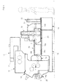
- Fig. 2 is a view of a calender for testing according to a first embodiment.
- the calender for testing according to the first embodiment includes a two-roll module 12, a main body modules 14, a take-off module 16, a base module 18, a cooling module 20, and a winder module 22.
- the modules 12, 14, 16, 20, and 22 include each of frames 12a, 14a, 16a, 20a, and 22a, and a direct drive unit (not shown) which is directly mounted to each of the frames 12a, 14a, 16a, 20a, and 22a respectively.
- the two-roll module 12 is directly and detachably fixed to an upper surface (upper side in Fig. 2 ) of the main body module 14, and the take-off module 16 is directly and detachably fixed to a rear side surface (right side in Fig. 2 ) of the main body module 14.
- the take-off module 16 may be positioned by a key, a pin, centering location, fitting, or the like, and detachably fixed by a bolt and a nut.
- the two-roll module 12 includes two rolls 12b and 12c which roll or mix a resin material 1.
- each of two rolls 12b and 12c is driven to rotate around the respective axes by the direct drive unit (not shown).
- the resin material 1 is supplied between two rolls 12b and 12c from the upside, and the resin material 1 is pressurized and rolled between two rolls 12b and 12c.
- two rolls 12b and 12c may mix the resin material 1 between two rolls.
- the main body module 14 includes three rolls 14b, 14c, and 14d which roll the resin material 1.
- each of three rolls 14b, 14c, and 14d is driven to rotate around the respective axes by the direct drive unit (not shown).
- the resin material 1 is transferred between the rolls 14b and 14c from the two-roll module 12, the resin material 1 is rolled between the rolls 14b and 14c, and subsequently, the resin material is rolled between the rolls 14c and 14d.
- the resin material 1 passing through the main body module 14 is formed in a film shape by three rolls 14b, 14c, and 14d.
- the resin material having a film shape is referred to as a resin film 2.
- a guide roller 15 which guides the resin film 2 to the take-off rolls 16b and 16c is provided at the rear of the main body module 14.
- the guide roller 15 may be a free roller which freely rotates around the axis.
- the take-off module 16 includes take-off rolls 16b and 16c which separate the resin film 2 from the main body module 14.
- the take-off rolls 16b and 16c are able to rotate around the respective axes, and have a function separating the resin film 2 from the roll 14d of the main body module 14.
- the take-off rolls 16b and 16c are a driving roller which is driven to rotate by a driving device (not shown). However, the take-off rolls may be a free roller which freely rotates around the axis.
- the base module 18 is directly and detachably fixed the main body module 14 on the upper surface, and includes a common rail 18a which horizontally extends to the rear.
- the common rail 18a is a horizontal rail which is perpendicular to shaft centers of the rolls 14b, 14c, and 14d.
- the common rail 18a includes a V groove in a portion thereof and is able to accurately position a width direction position of the main body module 14.
- the main body module 14 may be positioned by a key, a pin, centering location, fitting, or the like, and detachably fixed by a bolt and a nut.
- the cooling module 20 and the winder module 22 are fixed so as to move on and to be attached to and detached from the upper surface of the base module 18 along the common rail 18a.
- the fixing means may grip a leg portion (not shown) of the cooling module 20 or the winder module 22 which is positioned on the upper surface of the base module 18 by a gripping member which is fixed to the upper surface of the base module 18 by a bolt or the like.
- the cooling module 20 or the winder module 22 is able to freely move along the common rail 18a and is able to be fixed at an arbitrary position by the gripping member.
- the cooling module 20 cools the resin film 2 at the rear of the main body module 14.
- the cooling modules 20 includes a plurality of (four in this example) cooling rolls 20b, and each of the cooling rolls 20b is driven to rotate and is cooled by a cooling medium which flows inside. Each of the cooling rolls cools the resin film by contracting the resin film 2 transferred from the take-off module 16.
- the winder module 22 winds the resin film 2 at the rear of the cooling module 20.
- the winder modules 22 includes a winder roll 22b which is driven to rotate about the shaft center and winds the resin film 2 transferred from the cooling module 20.
- a test which combines the two-roll module 12, the main body module 14, the take-off module 16, the base module 18, the cooling module 20, and the winder module 22 is able to be performed. Moreover, in this case, since the cooling module 20 and the winder module 22 are able to move along the common rail 18a on the upper surface of the base module 18, the disposition is easily changed, and a line configuration is able to be changed freely according to the use.
- Fig. 3 is a view of a calender for testing according to a second embodiment.
- the calender for testing according to the second embodiment further includes an extrusion modules 10, a T-die 11, an embossing modules 24, and a trimming modules 26.
- a frame 10a of the extrusion module 10 is directly and detachably fixed to the rear side surface (right side in Fig. 3 ) of the frame 12a of the two-roll module 12, and the extrusion module 10 kneads and extrudes the resin material 1.
- the extrusion module 10 includes a resin supply port 10b to which the resin material is supplied, a screw 10c which is provided in the inner space of the extrusion module, and a resin discharge port 10d.
- the resin material 1 is supplied to the resin supply port 10b, the resin material, 1 is kneaded and mixed while being transferred from the rear side to the front side by the screw 10c, and the resin material is discharged from the resin discharge port 10d.
- the screw 10c in which a shaft extends from the rear side (right side in Fig. 3 ) to the front side is rotated around the axis by a direct drive unit (not shown), and therefore, the resin material passes between spiral grooves which form the screw 10c and is transferred from the rear side to the front side.
- the T-die 11 is directly and detachably fixed to the front side surface of the extrusion module 10 and supplies the kneaded resin material 1 downward.
- the extrusion module 10 and the T-die 11 may be positioned by a key, a pin, centering location, fitting, or the like, and detachably fixed by a bolt and a nut.
- a frame 24a of the embossing module 24 and a frame 26a of the trimming module 26 each are fixed so as to move on and to be attached to and detached from the upper surface of the base module 18 along the common rail 18a. Similar to the cooling module 20 and the winder module 22, the fixing means is able to freely move along the common rail 18a and is able to be fixed at an arbitrary position by the gripping member.
- the embossing modules 24 includes an embossing roll 24b which is driven to rotate, and applies a pattern to one surface or both surfaces of the resin film 2.
- the trimming module 26 includes a trimming pinch roll 26b which is driven to rotate, and cuts off an end of the resin film 2.
- a test which combines the extrusion module 10, the T-die 11, the embossing module 24, and the trimming module 26 is able to be performed.
- the cooling module 20, the winder module 22, the embossing module 24, and the trimming module 26 are able to move along the common rail 18a on the upper surface of the base module 18, the disposition is easily changed, and a line configuration is able to be changed freely according to the use.
- the configuration is able to be used while removing the T-die 11, necessity of the T-die 11 is able to be tested.
- Fig. 4 is a view of a calender for testing according to a third embodiment.
- the calender for testing according to the third embodiment further includes an extension base 19, an unwinding module 28, and an annealing module 30.
- the extension base 19 is directly and detachably fixed to the rear side surface (right side in Fig. 4 ) of the base module 18.
- the extension base 19 may be positioned by a key, a pin, centering location, fitting, or the like, and detachably fixed by a bolt and a nut.
- the extension base 19 includes a common rail 19a which horizontally extends to the rear side on the upper surface of the extension base.
- the common rail 19a is configured so as to extend the common rail 18a.
- the base module 18 and the extension base 19 may be integrated, and in this case, the common rails 18a and 19a may be the same rail as each other.
- a frame 28a of the unwinding module 28 is directly and detachably fixed to the front side surface of the frame 14a of the main body module 14, and the unwinding module 28 unwinds a second resin film 3 to the main body module 14.
- the unwinding module 28 may be positioned by a key, a pin, centering location, fitting, or the like, and detachably fixed by a bolt and a nut.
- a frame 30a of the annealing module 30 is disposed between the take-off module 16 and the embossing module 24, and the annealing module removes distortion of the resin film.
- the annealing module 30 includes a plurality of rolls 30b, and the distortion of the resin film is removed by warn air while the resin film is guided along the plurality of rolls. In this case, the distortion of the resin film 2 or a laminate film 4 in which the second resin film 3 is laminated on the resin film 2 is removed.
- a test which combines the unwinding module 28 and the annealing module 30 is able to be performed.
- the cooling module 20, the winder module 22, the embossing module 24, the trimming module 26, and the annealing module 30 are able to move along the common rails 18a and 19a on the upper surface of the base module 18, the disposition is easily changed, and a line configuration is able to be changed freely according to the use.
- Fig. 5 is a configuration diagram of a test device using some modules according to the present embodiment.
- the above-described extrusion module 10, the T-die 11, and the two-roll module 12 are fixed to an upper portion of an auxiliary base 32.
- a single test or a combination test of the extrusion module 10, the T-die 11, and the two-roll module 12 is able to be performed.
- the take-off module 16 since the take-off module 16, the cooling module 20, the winder module 22, the embossing module 24, the trimming module 26, and the annealing module 30 are able to move along the common rail on the upper surface of the base module 18, the disposition is easily changed to any order and intervals, and a line configuration is able to be changed freely according to the use.
- the two-roll module 12, the take-off module 16, and the unwinding module 28 are directly and detachably fixed to the main body module 14, the modules are able to be used in the state of being removed as necessary, and the size of the entire device at the time of the test is able to be decreased.
- the calendering test (rolling and film forming), the embossing test, the extrusion test (T-die film forming), the polishing test (two-roll rolling), the lamination layer test, the laminate test, and the annealing test are able to be performed individually or in combination according to combination of the modules.
- the needed tests are able to be performed individually using a small amount of test materials in each step.
Landscapes
- Engineering & Computer Science (AREA)
- Mechanical Engineering (AREA)
- Casting Or Compression Moulding Of Plastics Or The Like (AREA)
Abstract
Description
- The present invention relates to a calender which forms a resin film from a thermoplastic resin material such as plastic or rubber, and particularly, relates to a calender for testing for performing some tests in each stage according to development steps of a resin and a film forming.
- As illustrated in
Fig. 1 , a calender includes acontinuous kneader 81, a plurality of (five in example ofFig. 1 )rolling rolls off roll 85, a plurality of (four in example ofFig. 1 )cooling rolls winding roll 89, and the like. - A molten resin material is supplied to the
continuous kneader 81. The resin material is kneaded by thecontinuous kneader 81 and supplied between a first rollingroll 83a and a second rollingroll 83b. Thereafter, the resin material is rolled between the first and thesecond rolling rolls roll 83b and a third rollingroll 83c, is rolled between the third rollingroll 83c and a fourth rollingroll 83d, is rolled between the fourth rollingroll 83d and a fifthrolling roll 83e, and is formed a resin film. The resin film is separated from the fifth rollingroll 83e by the take-off roll 85 and is transferred to first tofourth cooling rolls fourth cooling rolls winding roll 89. - For example, the above-described calender is described in
Patent Literatures -
- PTL 1: Japanese Patent No.
2781836 - PAL 2: Japanese Patent No.
3968879 - In a case where a new film product is developed using a new resin material, a calendering test (rolling and film forming), an embossing test, an extrusion test (T-die film forming), a polishing test (two-roll rolling), a lamination layer test, a laminate test, and an annealing test need to be performed.
- Moreover, in a case where a new film product is developed using a new resin material, for example, the tests need to be preformed according to the following steps.
- (1) First Step: Discharge Test from Extruder (Relationship Verification of Resin Viscosity, Discharge Temperature, and Discharge Quantity)
- (2) Second Step: Detachment Test from Roll (Detachability Versification)
- (3) Third Step: Rolling Test (Verification of Temperature Condition, Surface Nature, Detachment strength, Swell Ratio, Elongation Percentage, or the like)
- (4) Fourth Step: Sheeting Test (Verification of Thickness, Surface Nature, Performance, or the like)
- (5) Fifth Step: Commercialization Test (Performance Versification as Product having Additional Function such as Annealing, Surface Reforming, or the like)
- However, in the above-described calender in the related art, each of the tests is not able to be performed individually, and thereby, the entire device having a large size needs to be operated, and a large amount of test material is also required.
- An object of the present invention is to provide a calendar for testing capable of individually performing a plurality of tests for developing a new film product using a new resin material using a small amount of test materials.
- According to the present invention, there is provided a calender for testing which forms a resin film from a resin material including:
- a two-roll module including two rolls which roll or mix the resin material;
- a main body modules including three rolls which roll the resin material;
- a take-off modules including a take-off roll which separates the resin film from the main body module,
- the two-roll module being directly and detachably fixed to an upper surface of the main body modules and
- the take-off module being directly and detachably fixed to a rear side surface of the main body module,
- a base module which directly and detachably fixes the main body module on an upper surface and has a common rail horizontally extending to the rear of the base module;
- a cooling module which cools the resin film at the rear of the main body module; and
- a winder module which winds the resin film at the rear of the cooling module,
- wherein the cooling module and the winder module are fixed so as to move on and to be attached to and detached from an upper surface of the base module along the common rail.
- According to an embodiment of the present invention, the calender for testing further includes an embossing module which applies a pattern to the resin film,
a trimming module which cuts off an end of the resin film, or
an annealing module which removes distortion of the resin film,
wherein each of the embossing module, the trimming module, and the annealing modules is fixed so as to move on and to be attached to and detached from the upper surface of the base module along the common rail. - In addition, the calender for testing further includes an extrusion modules which is directly and detachably fixed to a rear side surface of the two-roll module and kneads and extrudes the resin material.
- Moreover, the calender for testing further includes a T-die which is directly and detachably fixed to a front side surface of the extrusion module and supplies the kneaded resin material downward.
- In addition, the calender for testing further includes an unwinding module which is directly and detachably fixed to a front side surface of the main body module and unwinds a second resin film to the main body module.
- Moreover, each of the modules includes respective frames and respective direct drive units which are directly mounted to the frames.
- According to the configuration of the present invention described above, since the cooling module and the winder module are able to move along the common rail on the upper surface of the base module, the disposition is easily changed, and a line configuration is able to be changed freely according to the use.
In addition, since the two-roll module and the take-off module are directly and detachably fixed to the main body module, the modules are able to be used in the state of being removed as necessary, and the size of the entire device at the time of the test is able to be decreased.
Accordingly, it is possible to individually perform a plurality of tests for developing a new film product using a new resin material using a small amount of test materials. -
-
Fig. 1 illustrates a configuration of a calender of the related art. -
Fig. 2 is a view of a calender for testing according to a first embodiment. -
Fig. 3 is a view of a calender for testing according to a second embodiment. -
Fig. 4 is a view of a calender for testing according to a third embodiment. -
Fig. 5 is a configuration diagram of a test device using some modules according to the present embodiment. - Preferred embodiment of the present invention will be described with reference to drawings. Moreover, in the drawings, the common portions are denoted by the same reference numerals, and the overlapping descriptions are omitted.
-
Fig. 2 is a view of a calender for testing according to a first embodiment.
InFig. 2 , the calender for testing according to the first embodiment includes a two-roll module 12, amain body modules 14, a take-off module 16, abase module 18, acooling module 20, and awinder module 22. - The
modules frames frames - Moreover, the two-
roll module 12 is directly and detachably fixed to an upper surface (upper side inFig. 2 ) of themain body module 14, and the take-off module 16 is directly and detachably fixed to a rear side surface (right side inFig. 2 ) of themain body module 14.
For example, the take-off module 16 may be positioned by a key, a pin, centering location, fitting, or the like, and detachably fixed by a bolt and a nut. - The two-
roll module 12 includes tworolls resin material 1.
In this example, each of tworolls resin material 1 is supplied between tworolls resin material 1 is pressurized and rolled between tworolls
Moreover, tworolls resin material 1 between two rolls. - The
main body module 14 includes threerolls resin material 1.
In this example, each of threerolls resin material 1 is transferred between therolls roll module 12, theresin material 1 is rolled between therolls rolls resin material 1 passing through themain body module 14 is formed in a film shape by threerolls resin film 2. - Moreover, a
guide roller 15 which guides theresin film 2 to the take-off rolls 16b and 16c is provided at the rear of themain body module 14. Theguide roller 15 may be a free roller which freely rotates around the axis. - The take-
off module 16 includes take-off rolls 16b and 16c which separate theresin film 2 from themain body module 14.
The take-off rolls 16b and 16c are able to rotate around the respective axes, and have a function separating theresin film 2 from theroll 14d of themain body module 14. The take-off rolls 16b and 16c are a driving roller which is driven to rotate by a driving device (not shown). However, the take-off rolls may be a free roller which freely rotates around the axis. - The
base module 18 is directly and detachably fixed themain body module 14 on the upper surface, and includes acommon rail 18a which horizontally extends to the rear.
Thecommon rail 18a is a horizontal rail which is perpendicular to shaft centers of therolls common rail 18a includes a V groove in a portion thereof and is able to accurately position a width direction position of themain body module 14.
For example, themain body module 14 may be positioned by a key, a pin, centering location, fitting, or the like, and detachably fixed by a bolt and a nut. - The
cooling module 20 and thewinder module 22 are fixed so as to move on and to be attached to and detached from the upper surface of thebase module 18 along thecommon rail 18a.
For example, the fixing means may grip a leg portion (not shown) of thecooling module 20 or thewinder module 22 which is positioned on the upper surface of thebase module 18 by a gripping member which is fixed to the upper surface of thebase module 18 by a bolt or the like. In this case, by loosening the bolt or the like, thecooling module 20 or thewinder module 22 is able to freely move along thecommon rail 18a and is able to be fixed at an arbitrary position by the gripping member. - The
cooling module 20 cools theresin film 2 at the rear of themain body module 14.
The coolingmodules 20 includes a plurality of (four in this example) cooling rolls 20b, and each of the cooling rolls 20b is driven to rotate and is cooled by a cooling medium which flows inside. Each of the cooling rolls cools the resin film by contracting theresin film 2 transferred from the take-off module 16. - The
winder module 22 winds theresin film 2 at the rear of thecooling module 20.
Thewinder modules 22 includes awinder roll 22b which is driven to rotate about the shaft center and winds theresin film 2 transferred from thecooling module 20. - According to the calender for testing having the above-described configuration, a test which combines the two-
roll module 12, themain body module 14, the take-off module 16, thebase module 18, thecooling module 20, and thewinder module 22 is able to be performed.
Moreover, in this case, since thecooling module 20 and thewinder module 22 are able to move along thecommon rail 18a on the upper surface of thebase module 18, the disposition is easily changed, and a line configuration is able to be changed freely according to the use. -
Fig. 3 is a view of a calender for testing according to a second embodiment.
InFig. 3 , the calender for testing according to the second embodiment further includes anextrusion modules 10, a T-die 11, anembossing modules 24, and a trimmingmodules 26. - A
frame 10a of theextrusion module 10 is directly and detachably fixed to the rear side surface (right side inFig. 3 ) of theframe 12a of the two-roll module 12, and theextrusion module 10 kneads and extrudes theresin material 1. - The
extrusion module 10 includes aresin supply port 10b to which the resin material is supplied, ascrew 10c which is provided in the inner space of the extrusion module, and aresin discharge port 10d. Theresin material 1 is supplied to theresin supply port 10b, the resin material, 1 is kneaded and mixed while being transferred from the rear side to the front side by thescrew 10c, and the resin material is discharged from theresin discharge port 10d.
In this case, thescrew 10c in which a shaft extends from the rear side (right side inFig. 3 ) to the front side is rotated around the axis by a direct drive unit (not shown), and therefore, the resin material passes between spiral grooves which form thescrew 10c and is transferred from the rear side to the front side. - The T-die 11 is directly and detachably fixed to the front side surface of the
extrusion module 10 and supplies the kneadedresin material 1 downward.
For example, theextrusion module 10 and the T-die 11 may be positioned by a key, a pin, centering location, fitting, or the like, and detachably fixed by a bolt and a nut. - A
frame 24a of theembossing module 24 and aframe 26a of thetrimming module 26 each are fixed so as to move on and to be attached to and detached from the upper surface of thebase module 18 along thecommon rail 18a. Similar to thecooling module 20 and thewinder module 22, the fixing means is able to freely move along thecommon rail 18a and is able to be fixed at an arbitrary position by the gripping member. - The
embossing modules 24 includes anembossing roll 24b which is driven to rotate, and applies a pattern to one surface or both surfaces of theresin film 2.
Thetrimming module 26 includes atrimming pinch roll 26b which is driven to rotate, and cuts off an end of theresin film 2. - According to the calender for testing having the above-described configuration, in addition to the configuration of
Fig. 2 , a test which combines theextrusion module 10, the T-die 11, theembossing module 24, and thetrimming module 26 is able to be performed.
Moreover, in this case, since thecooling module 20, thewinder module 22, theembossing module 24, and thetrimming module 26 are able to move along thecommon rail 18a on the upper surface of thebase module 18, the disposition is easily changed, and a line configuration is able to be changed freely according to the use.
Moreover, since the configuration is able to be used while removing the T-die 11, necessity of the T-die 11 is able to be tested. -
Fig. 4 is a view of a calender for testing according to a third embodiment.
InFig. 4 , the calender for testing according to the third embodiment further includes anextension base 19, an unwindingmodule 28, and anannealing module 30. - The
extension base 19 is directly and detachably fixed to the rear side surface (right side inFig. 4 ) of thebase module 18. For example, theextension base 19 may be positioned by a key, a pin, centering location, fitting, or the like, and detachably fixed by a bolt and a nut.
Moreover, theextension base 19 includes acommon rail 19a which horizontally extends to the rear side on the upper surface of the extension base. Thecommon rail 19a is configured so as to extend thecommon rail 18a.
Moreover, thebase module 18 and theextension base 19 may be integrated, and in this case, thecommon rails - A
frame 28a of the unwindingmodule 28 is directly and detachably fixed to the front side surface of theframe 14a of themain body module 14, and the unwindingmodule 28 unwinds asecond resin film 3 to themain body module 14.
For example, the unwindingmodule 28 may be positioned by a key, a pin, centering location, fitting, or the like, and detachably fixed by a bolt and a nut. - A
frame 30a of theannealing module 30 is disposed between the take-off module 16 and theembossing module 24, and the annealing module removes distortion of the resin film.
Theannealing module 30 includes a plurality ofrolls 30b, and the distortion of the resin film is removed by warn air while the resin film is guided along the plurality of rolls.
In this case, the distortion of theresin film 2 or alaminate film 4 in which thesecond resin film 3 is laminated on theresin film 2 is removed. - According to the calender for testing having the above-described configuration, in addition to the configuration of
Fig. 3 , a test which combines the unwindingmodule 28 and theannealing module 30 is able to be performed.
Moreover, in this case, since thecooling module 20, thewinder module 22, theembossing module 24, thetrimming module 26, and theannealing module 30 are able to move along thecommon rails base module 18, the disposition is easily changed, and a line configuration is able to be changed freely according to the use. -
Fig. 5 is a configuration diagram of a test device using some modules according to the present embodiment.
In this test device, the above-describedextrusion module 10, the T-die 11, and the two-roll module 12 are fixed to an upper portion of anauxiliary base 32.
According to the test device having this configuration, a single test or a combination test of theextrusion module 10, the T-die 11, and the two-roll module 12 is able to be performed. - According to the above-described configuration, since the take-
off module 16, thecooling module 20, thewinder module 22, theembossing module 24, thetrimming module 26, and theannealing module 30 are able to move along the common rail on the upper surface of thebase module 18, the disposition is easily changed to any order and intervals, and a line configuration is able to be changed freely according to the use.
In addition, since the two-roll module 12, the take-off module 16, and the unwindingmodule 28 are directly and detachably fixed to themain body module 14, the modules are able to be used in the state of being removed as necessary, and the size of the entire device at the time of the test is able to be decreased.
Accordingly, the calendering test (rolling and film forming), the embossing test, the extrusion test (T-die film forming), the polishing test (two-roll rolling), the lamination layer test, the laminate test, and the annealing test are able to be performed individually or in combination according to combination of the modules.
In addition, in a case where a new film product is developed using a new resin material, the needed tests are able to be performed individually using a small amount of test materials in each step. - Moreover, the present invention is not limited to the above-described embodiments, and it is needless to say that various modifications may be added and obtained within a scope which does not depart from the gist of the invention.
-
- 1: resin material, 2: resin film
- 3: second resin film, 4: laminate film
- 10: extrusion module, 10a: frame, 10b: resin supply port
- 10c: screw, 10d: resin discharge port
- 11: T-die, 12: two-roll module
- 12a: frame, 12b and 12c: roll
- 14: main body module, 14a: frame
- 14b, 14c, and 14d: roll, 15: guide roller
- 16: take-off module, 16a: frame
- 16b, 16c: take-off roll
- 18: base module, 18a: common rail
- 19: extension base, 19a: common rail
- 20: cooling module, 20a: frame, 20b: cooling roll
- 22: winder module, 22a: frame, 22b: winder roll
- 24: embossing module, 24a: frame, 24b: embossing roll
- 26: trimming module, 26a: frame
- 26b: trimming pinch roll
- 28: unwinding roll, 28a: frame
- 30: annealing module, 30a: frame, 30b: roll
- 32: auxiliary base
Claims (6)
- A calender for testing which forms a resin film from a resin material, comprising:a two-roll module including two rolls which roll or mix the resin material;a main body module including three rolls which roll the rein material;a take-off module including a take-off roll which separates the resin film from the main body module,the two-roll module being directly and detachably fixed to an upper surface of the main body module, andthe take-off module being directly and detachably fixed to a rear side surface of the main body module;a base module which directly and detachably fixes the main body module on an upper surface and has a common rail horizontally extending to the rear of the base module;a cooling module which cools the resin film at the rear of the main body module; anda winder module which winds the resin film at the rear of the cooling module,wherein the cooling module and the winder module are fixed so as to move on and to be attached to and detached from an upper surface of the base module along the common rail.
- The calender for testing according to claim 1, further comprising:an embossing module which applies a pattern to the resin film;a trimming module which cuts off an end of the resin film; oran annealing module which removes distortion of the resin film,wherein each of the embossing module, the trimming module, and the annealing module is fixed so as to move on and to be attached to and detached from the upper surface of the base module along the common rail.
- The calendar for testing according to claim 1, further comprising:an extrusion module which is directly and detachably fixed to a rear side surface of the two-roll module and kneads and extrudes the resin material.
- The calender for testing according to claim 3, further comprising:,
a T-die which is directly and detachably fixed to a front side surface of the extrusion module and supplies the kneaded resin material downward. - The calender for testing according to claim 1, further comprising:an unwinding module which is directly and detachably fixed to a front side surface of the main body module and unwinds a second resin film to the main body module.
- The calendar for testing according to any one of claims 1 to 5,
wherein each of the modules includes respective frames and respective direct drive units which are directly mounted to the frames.
Applications Claiming Priority (2)
| Application Number | Priority Date | Filing Date | Title |
|---|---|---|---|
| JP2010092487A JP5538042B2 (en) | 2010-04-13 | 2010-04-13 | Calendar device for testing |
| PCT/JP2011/058790 WO2011129258A1 (en) | 2010-04-13 | 2011-04-07 | Calender for testing |
Publications (3)
| Publication Number | Publication Date |
|---|---|
| EP2559539A1 true EP2559539A1 (en) | 2013-02-20 |
| EP2559539A4 EP2559539A4 (en) | 2017-01-11 |
| EP2559539B1 EP2559539B1 (en) | 2018-10-10 |
Family
ID=44798634
Family Applications (1)
| Application Number | Title | Priority Date | Filing Date |
|---|---|---|---|
| EP11768779.8A Active EP2559539B1 (en) | 2010-04-13 | 2011-04-07 | Calender for testing |
Country Status (5)
| Country | Link |
|---|---|
| EP (1) | EP2559539B1 (en) |
| JP (1) | JP5538042B2 (en) |
| KR (1) | KR101306854B1 (en) |
| TW (1) | TWI444281B (en) |
| WO (1) | WO2011129258A1 (en) |
Cited By (1)
| Publication number | Priority date | Publication date | Assignee | Title |
|---|---|---|---|---|
| CN111976073A (en) * | 2020-08-04 | 2020-11-24 | 湖州骏才科技有限公司 | Calender for processing plastic film for film production |
Families Citing this family (4)
| Publication number | Priority date | Publication date | Assignee | Title |
|---|---|---|---|---|
| KR102144770B1 (en) * | 2018-09-17 | 2020-08-18 | (주)창영기계 | The device for manufacturing thin sheet/film and the method of the same |
| CN109203497B (en) * | 2018-10-15 | 2024-05-07 | 常州金纬片板设备制造有限公司 | Five-roller forming machine for composite floor |
| TWI680863B (en) * | 2018-10-19 | 2020-01-01 | 彩揚塑膠工業股份有限公司 | Manufacturing method and manufacturing device for producing embossed adhesive tape of various widths |
| CN116690876B (en) * | 2023-08-07 | 2023-10-27 | 山东汇锋新材料有限公司 | Efficient calender |
Family Cites Families (7)
| Publication number | Priority date | Publication date | Assignee | Title |
|---|---|---|---|---|
| GB1217548A (en) * | 1967-11-30 | 1970-12-31 | Schloemann Ag | Improvements in calendars, particularly in drawing calendars for the production of webs of film |
| US4408974A (en) * | 1982-01-20 | 1983-10-11 | Comerio Ercole, S.P.A. | Mobile film stretching unit |
| JP3293183B2 (en) * | 1992-08-18 | 2002-06-17 | 石川島播磨重工業株式会社 | Calendar molding machine |
| JP3669392B2 (en) * | 1996-02-22 | 2005-07-06 | 石川島播磨重工業株式会社 | Calendar facilities |
| JPH11232824A (en) * | 1998-02-13 | 1999-08-27 | Kao Corp | Tape reader manufacturing method |
| JP4717551B2 (en) * | 2005-08-23 | 2011-07-06 | 東芝機械株式会社 | Sheet forming apparatus and roll gap control method |
| JP2008296592A (en) * | 2008-07-02 | 2008-12-11 | Cte Co Ltd | Method and apparatus for producing thermoplastic synthetic resin sheet or film |
-
2010
- 2010-04-13 JP JP2010092487A patent/JP5538042B2/en active Active
-
2011
- 2011-04-07 KR KR1020127019698A patent/KR101306854B1/en active Active
- 2011-04-07 WO PCT/JP2011/058790 patent/WO2011129258A1/en not_active Ceased
- 2011-04-07 EP EP11768779.8A patent/EP2559539B1/en active Active
- 2011-04-11 TW TW100112431A patent/TWI444281B/en active
Non-Patent Citations (1)
| Title |
|---|
| See references of WO2011129258A1 * |
Cited By (1)
| Publication number | Priority date | Publication date | Assignee | Title |
|---|---|---|---|---|
| CN111976073A (en) * | 2020-08-04 | 2020-11-24 | 湖州骏才科技有限公司 | Calender for processing plastic film for film production |
Also Published As
| Publication number | Publication date |
|---|---|
| KR20120106875A (en) | 2012-09-26 |
| EP2559539A4 (en) | 2017-01-11 |
| TW201204526A (en) | 2012-02-01 |
| WO2011129258A1 (en) | 2011-10-20 |
| EP2559539B1 (en) | 2018-10-10 |
| KR101306854B1 (en) | 2013-09-10 |
| JP2011218730A (en) | 2011-11-04 |
| TWI444281B (en) | 2014-07-11 |
| JP5538042B2 (en) | 2014-07-02 |
Similar Documents
| Publication | Publication Date | Title |
|---|---|---|
| EP2559539B1 (en) | Calender for testing | |
| AU639210B2 (en) | Method and apparatus for helical cutting of a flexible tubular sheet of polymeric material | |
| EP3188285A1 (en) | Microporous membrane roll for battery separators and method for producing same | |
| KR20240150730A (en) | Stretching equipment for manufacturing separator and method for manufacturing separator using the same | |
| JP2014073589A (en) | Manufacturing device and manufacturing method of rubber strip | |
| KR101156192B1 (en) | Apparatus and method for manufacturing a thin blown film | |
| EP2559538B1 (en) | Calender | |
| CN114347613B (en) | Microcrystal point high-transparency self-adhesive polyethylene protective film and preparation method thereof | |
| JP2018177998A (en) | Removable surface protection film | |
| CN108251006B (en) | Polypropylene type protective film for photosensitive dry film and production method thereof | |
| JP2010120183A (en) | Tire manufacturing apparatus and tire manufacturing method | |
| JP2009072915A (en) | Molded plate manufacturing method and manufacturing apparatus | |
| CN114472469B (en) | Disassembling device and disassembling equipment | |
| CN111056353B (en) | A laminating machine with automatic tension adjustment | |
| JPWO2013001922A1 (en) | Manufacturing method of tire and bead member | |
| JP5104477B2 (en) | Inflation molding machine | |
| JP5184564B2 (en) | Method for producing easy delamination sheet and delamination sheet obtained by the production method | |
| CN222271192U (en) | Preparation device of sodium ion battery diaphragm | |
| CN222662658U (en) | A laminating device for producing vehicle display screen | |
| CN120245555A (en) | Electronic process die-cutting co-extruded protective film and preparation method thereof | |
| JP6424094B2 (en) | Rubber strip manufacturing equipment | |
| CN211220808U (en) | Edge trimmer for nano adhesive film | |
| CN101327642A (en) | Front-back side film-wearing composite apparatus of digital photographic paper production line and film-wearing composite method thereof | |
| JP2017217892A (en) | Rubber molding apparatus and rubber member molding method | |
| JP2016150468A (en) | Device for production of rubber strip |
Legal Events
| Date | Code | Title | Description |
|---|---|---|---|
| PUAI | Public reference made under article 153(3) epc to a published international application that has entered the european phase |
Free format text: ORIGINAL CODE: 0009012 |
|
| 17P | Request for examination filed |
Effective date: 20121015 |
|
| AK | Designated contracting states |
Kind code of ref document: A1 Designated state(s): AL AT BE BG CH CY CZ DE DK EE ES FI FR GB GR HR HU IE IS IT LI LT LU LV MC MK MT NL NO PL PT RO RS SE SI SK SM TR |
|
| DAX | Request for extension of the european patent (deleted) | ||
| RA4 | Supplementary search report drawn up and despatched (corrected) |
Effective date: 20161209 |
|
| RIC1 | Information provided on ipc code assigned before grant |
Ipc: B29C 43/34 20060101ALI20161205BHEP Ipc: B29L 7/00 20060101ALI20161205BHEP Ipc: B29C 43/28 20060101ALI20161205BHEP Ipc: B29C 43/24 20060101AFI20161205BHEP Ipc: B29C 43/46 20060101ALI20161205BHEP |
|
| REG | Reference to a national code |
Ref country code: DE Ref legal event code: R079 Ref document number: 602011052796 Country of ref document: DE Free format text: PREVIOUS MAIN CLASS: B29C0043460000 Ipc: B29C0043240000 |
|
| GRAP | Despatch of communication of intention to grant a patent |
Free format text: ORIGINAL CODE: EPIDOSNIGR1 |
|
| STAA | Information on the status of an ep patent application or granted ep patent |
Free format text: STATUS: GRANT OF PATENT IS INTENDED |
|
| RIC1 | Information provided on ipc code assigned before grant |
Ipc: B29C 43/24 20060101AFI20180419BHEP Ipc: B29L 7/00 20060101ALN20180419BHEP Ipc: B29C 43/46 20060101ALI20180419BHEP |
|
| RIC1 | Information provided on ipc code assigned before grant |
Ipc: B29L 7/00 20060101ALN20180502BHEP Ipc: B29C 43/24 20060101AFI20180502BHEP Ipc: B29C 43/46 20060101ALI20180502BHEP |
|
| INTG | Intention to grant announced |
Effective date: 20180518 |
|
| RAP1 | Party data changed (applicant data changed or rights of an application transferred) |
Owner name: IHI CORPORATION Owner name: IHI LOGISTICS & MACHINERY CORPORATION |
|
| GRAS | Grant fee paid |
Free format text: ORIGINAL CODE: EPIDOSNIGR3 |
|
| GRAA | (expected) grant |
Free format text: ORIGINAL CODE: 0009210 |
|
| STAA | Information on the status of an ep patent application or granted ep patent |
Free format text: STATUS: THE PATENT HAS BEEN GRANTED |
|
| AK | Designated contracting states |
Kind code of ref document: B1 Designated state(s): AL AT BE BG CH CY CZ DE DK EE ES FI FR GB GR HR HU IE IS IT LI LT LU LV MC MK MT NL NO PL PT RO RS SE SI SK SM TR |
|
| REG | Reference to a national code |
Ref country code: GB Ref legal event code: FG4D |
|
| REG | Reference to a national code |
Ref country code: CH Ref legal event code: EP Ref country code: AT Ref legal event code: REF Ref document number: 1050696 Country of ref document: AT Kind code of ref document: T Effective date: 20181015 |
|
| REG | Reference to a national code |
Ref country code: IE Ref legal event code: FG4D |
|
| REG | Reference to a national code |
Ref country code: DE Ref legal event code: R096 Ref document number: 602011052796 Country of ref document: DE |
|
| REG | Reference to a national code |
Ref country code: NL Ref legal event code: MP Effective date: 20181010 |
|
| REG | Reference to a national code |
Ref country code: LT Ref legal event code: MG4D |
|
| REG | Reference to a national code |
Ref country code: AT Ref legal event code: MK05 Ref document number: 1050696 Country of ref document: AT Kind code of ref document: T Effective date: 20181010 |
|
| PG25 | Lapsed in a contracting state [announced via postgrant information from national office to epo] |
Ref country code: NL Free format text: LAPSE BECAUSE OF FAILURE TO SUBMIT A TRANSLATION OF THE DESCRIPTION OR TO PAY THE FEE WITHIN THE PRESCRIBED TIME-LIMIT Effective date: 20181010 |
|
| PG25 | Lapsed in a contracting state [announced via postgrant information from national office to epo] |
Ref country code: AT Free format text: LAPSE BECAUSE OF FAILURE TO SUBMIT A TRANSLATION OF THE DESCRIPTION OR TO PAY THE FEE WITHIN THE PRESCRIBED TIME-LIMIT Effective date: 20181010 Ref country code: LV Free format text: LAPSE BECAUSE OF FAILURE TO SUBMIT A TRANSLATION OF THE DESCRIPTION OR TO PAY THE FEE WITHIN THE PRESCRIBED TIME-LIMIT Effective date: 20181010 Ref country code: NO Free format text: LAPSE BECAUSE OF FAILURE TO SUBMIT A TRANSLATION OF THE DESCRIPTION OR TO PAY THE FEE WITHIN THE PRESCRIBED TIME-LIMIT Effective date: 20190110 Ref country code: BG Free format text: LAPSE BECAUSE OF FAILURE TO SUBMIT A TRANSLATION OF THE DESCRIPTION OR TO PAY THE FEE WITHIN THE PRESCRIBED TIME-LIMIT Effective date: 20190110 Ref country code: LT Free format text: LAPSE BECAUSE OF FAILURE TO SUBMIT A TRANSLATION OF THE DESCRIPTION OR TO PAY THE FEE WITHIN THE PRESCRIBED TIME-LIMIT Effective date: 20181010 Ref country code: ES Free format text: LAPSE BECAUSE OF FAILURE TO SUBMIT A TRANSLATION OF THE DESCRIPTION OR TO PAY THE FEE WITHIN THE PRESCRIBED TIME-LIMIT Effective date: 20181010 Ref country code: PL Free format text: LAPSE BECAUSE OF FAILURE TO SUBMIT A TRANSLATION OF THE DESCRIPTION OR TO PAY THE FEE WITHIN THE PRESCRIBED TIME-LIMIT Effective date: 20181010 Ref country code: HR Free format text: LAPSE BECAUSE OF FAILURE TO SUBMIT A TRANSLATION OF THE DESCRIPTION OR TO PAY THE FEE WITHIN THE PRESCRIBED TIME-LIMIT Effective date: 20181010 Ref country code: IS Free format text: LAPSE BECAUSE OF FAILURE TO SUBMIT A TRANSLATION OF THE DESCRIPTION OR TO PAY THE FEE WITHIN THE PRESCRIBED TIME-LIMIT Effective date: 20190210 Ref country code: FI Free format text: LAPSE BECAUSE OF FAILURE TO SUBMIT A TRANSLATION OF THE DESCRIPTION OR TO PAY THE FEE WITHIN THE PRESCRIBED TIME-LIMIT Effective date: 20181010 |
|
| PG25 | Lapsed in a contracting state [announced via postgrant information from national office to epo] |
Ref country code: GR Free format text: LAPSE BECAUSE OF FAILURE TO SUBMIT A TRANSLATION OF THE DESCRIPTION OR TO PAY THE FEE WITHIN THE PRESCRIBED TIME-LIMIT Effective date: 20190111 Ref country code: RS Free format text: LAPSE BECAUSE OF FAILURE TO SUBMIT A TRANSLATION OF THE DESCRIPTION OR TO PAY THE FEE WITHIN THE PRESCRIBED TIME-LIMIT Effective date: 20181010 Ref country code: PT Free format text: LAPSE BECAUSE OF FAILURE TO SUBMIT A TRANSLATION OF THE DESCRIPTION OR TO PAY THE FEE WITHIN THE PRESCRIBED TIME-LIMIT Effective date: 20190210 Ref country code: AL Free format text: LAPSE BECAUSE OF FAILURE TO SUBMIT A TRANSLATION OF THE DESCRIPTION OR TO PAY THE FEE WITHIN THE PRESCRIBED TIME-LIMIT Effective date: 20181010 Ref country code: SE Free format text: LAPSE BECAUSE OF FAILURE TO SUBMIT A TRANSLATION OF THE DESCRIPTION OR TO PAY THE FEE WITHIN THE PRESCRIBED TIME-LIMIT Effective date: 20181010 |
|
| REG | Reference to a national code |
Ref country code: DE Ref legal event code: R097 Ref document number: 602011052796 Country of ref document: DE |
|
| PG25 | Lapsed in a contracting state [announced via postgrant information from national office to epo] |
Ref country code: DK Free format text: LAPSE BECAUSE OF FAILURE TO SUBMIT A TRANSLATION OF THE DESCRIPTION OR TO PAY THE FEE WITHIN THE PRESCRIBED TIME-LIMIT Effective date: 20181010 Ref country code: CZ Free format text: LAPSE BECAUSE OF FAILURE TO SUBMIT A TRANSLATION OF THE DESCRIPTION OR TO PAY THE FEE WITHIN THE PRESCRIBED TIME-LIMIT Effective date: 20181010 |
|
| PLBE | No opposition filed within time limit |
Free format text: ORIGINAL CODE: 0009261 |
|
| STAA | Information on the status of an ep patent application or granted ep patent |
Free format text: STATUS: NO OPPOSITION FILED WITHIN TIME LIMIT |
|
| PG25 | Lapsed in a contracting state [announced via postgrant information from national office to epo] |
Ref country code: RO Free format text: LAPSE BECAUSE OF FAILURE TO SUBMIT A TRANSLATION OF THE DESCRIPTION OR TO PAY THE FEE WITHIN THE PRESCRIBED TIME-LIMIT Effective date: 20181010 Ref country code: SK Free format text: LAPSE BECAUSE OF FAILURE TO SUBMIT A TRANSLATION OF THE DESCRIPTION OR TO PAY THE FEE WITHIN THE PRESCRIBED TIME-LIMIT Effective date: 20181010 Ref country code: EE Free format text: LAPSE BECAUSE OF FAILURE TO SUBMIT A TRANSLATION OF THE DESCRIPTION OR TO PAY THE FEE WITHIN THE PRESCRIBED TIME-LIMIT Effective date: 20181010 Ref country code: SM Free format text: LAPSE BECAUSE OF FAILURE TO SUBMIT A TRANSLATION OF THE DESCRIPTION OR TO PAY THE FEE WITHIN THE PRESCRIBED TIME-LIMIT Effective date: 20181010 |
|
| 26N | No opposition filed |
Effective date: 20190711 |
|
| PG25 | Lapsed in a contracting state [announced via postgrant information from national office to epo] |
Ref country code: SI Free format text: LAPSE BECAUSE OF FAILURE TO SUBMIT A TRANSLATION OF THE DESCRIPTION OR TO PAY THE FEE WITHIN THE PRESCRIBED TIME-LIMIT Effective date: 20181010 |
|
| REG | Reference to a national code |
Ref country code: CH Ref legal event code: PL |
|
| REG | Reference to a national code |
Ref country code: BE Ref legal event code: MM Effective date: 20190430 |
|
| GBPC | Gb: european patent ceased through non-payment of renewal fee |
Effective date: 20190407 |
|
| PG25 | Lapsed in a contracting state [announced via postgrant information from national office to epo] |
Ref country code: LU Free format text: LAPSE BECAUSE OF NON-PAYMENT OF DUE FEES Effective date: 20190407 Ref country code: MC Free format text: LAPSE BECAUSE OF FAILURE TO SUBMIT A TRANSLATION OF THE DESCRIPTION OR TO PAY THE FEE WITHIN THE PRESCRIBED TIME-LIMIT Effective date: 20181010 |
|
| PG25 | Lapsed in a contracting state [announced via postgrant information from national office to epo] |
Ref country code: GB Free format text: LAPSE BECAUSE OF NON-PAYMENT OF DUE FEES Effective date: 20190407 Ref country code: LI Free format text: LAPSE BECAUSE OF NON-PAYMENT OF DUE FEES Effective date: 20190430 Ref country code: CH Free format text: LAPSE BECAUSE OF NON-PAYMENT OF DUE FEES Effective date: 20190430 |
|
| PG25 | Lapsed in a contracting state [announced via postgrant information from national office to epo] |
Ref country code: FR Free format text: LAPSE BECAUSE OF NON-PAYMENT OF DUE FEES Effective date: 20190430 Ref country code: BE Free format text: LAPSE BECAUSE OF NON-PAYMENT OF DUE FEES Effective date: 20190430 |
|
| PG25 | Lapsed in a contracting state [announced via postgrant information from national office to epo] |
Ref country code: TR Free format text: LAPSE BECAUSE OF FAILURE TO SUBMIT A TRANSLATION OF THE DESCRIPTION OR TO PAY THE FEE WITHIN THE PRESCRIBED TIME-LIMIT Effective date: 20181010 |
|
| PG25 | Lapsed in a contracting state [announced via postgrant information from national office to epo] |
Ref country code: IE Free format text: LAPSE BECAUSE OF NON-PAYMENT OF DUE FEES Effective date: 20190407 |
|
| PG25 | Lapsed in a contracting state [announced via postgrant information from national office to epo] |
Ref country code: CY Free format text: LAPSE BECAUSE OF FAILURE TO SUBMIT A TRANSLATION OF THE DESCRIPTION OR TO PAY THE FEE WITHIN THE PRESCRIBED TIME-LIMIT Effective date: 20181010 |
|
| PG25 | Lapsed in a contracting state [announced via postgrant information from national office to epo] |
Ref country code: MT Free format text: LAPSE BECAUSE OF FAILURE TO SUBMIT A TRANSLATION OF THE DESCRIPTION OR TO PAY THE FEE WITHIN THE PRESCRIBED TIME-LIMIT Effective date: 20181010 Ref country code: HU Free format text: LAPSE BECAUSE OF FAILURE TO SUBMIT A TRANSLATION OF THE DESCRIPTION OR TO PAY THE FEE WITHIN THE PRESCRIBED TIME-LIMIT; INVALID AB INITIO Effective date: 20110407 |
|
| PG25 | Lapsed in a contracting state [announced via postgrant information from national office to epo] |
Ref country code: MK Free format text: LAPSE BECAUSE OF FAILURE TO SUBMIT A TRANSLATION OF THE DESCRIPTION OR TO PAY THE FEE WITHIN THE PRESCRIBED TIME-LIMIT Effective date: 20181010 |
|
| PGFP | Annual fee paid to national office [announced via postgrant information from national office to epo] |
Ref country code: DE Payment date: 20250305 Year of fee payment: 15 |
|
| PGFP | Annual fee paid to national office [announced via postgrant information from national office to epo] |
Ref country code: IT Payment date: 20260320 Year of fee payment: 16 |