EP2559471A2 - Filter core for use with pleated filter cartridges - Google Patents
Filter core for use with pleated filter cartridges Download PDFInfo
- Publication number
- EP2559471A2 EP2559471A2 EP12180639A EP12180639A EP2559471A2 EP 2559471 A2 EP2559471 A2 EP 2559471A2 EP 12180639 A EP12180639 A EP 12180639A EP 12180639 A EP12180639 A EP 12180639A EP 2559471 A2 EP2559471 A2 EP 2559471A2
- Authority
- EP
- European Patent Office
- Prior art keywords
- surface features
- filter core
- tubular body
- accordance
- filter
- Prior art date
- Legal status (The legal status is an assumption and is not a legal conclusion. Google has not performed a legal analysis and makes no representation as to the accuracy of the status listed.)
- Withdrawn
Links
- 239000012530 fluid Substances 0.000 claims description 27
- 238000001914 filtration Methods 0.000 claims description 24
- 238000000034 method Methods 0.000 claims description 17
- 238000005096 rolling process Methods 0.000 claims description 6
- 238000004519 manufacturing process Methods 0.000 claims description 2
- 230000006870 function Effects 0.000 description 9
- 239000000463 material Substances 0.000 description 6
- 239000002184 metal Substances 0.000 description 6
- 238000004140 cleaning Methods 0.000 description 5
- 239000000428 dust Substances 0.000 description 4
- 239000013618 particulate matter Substances 0.000 description 3
- 229920001169 thermoplastic Polymers 0.000 description 2
- 229910000831 Steel Inorganic materials 0.000 description 1
- 238000005299 abrasion Methods 0.000 description 1
- 230000003247 decreasing effect Effects 0.000 description 1
- 238000006073 displacement reaction Methods 0.000 description 1
- 230000002708 enhancing effect Effects 0.000 description 1
- 230000007717 exclusion Effects 0.000 description 1
- 230000007062 hydrolysis Effects 0.000 description 1
- 238000006460 hydrolysis reaction Methods 0.000 description 1
- 239000007788 liquid Substances 0.000 description 1
- 239000004033 plastic Substances 0.000 description 1
- 239000002861 polymer material Substances 0.000 description 1
- 230000000452 restraining effect Effects 0.000 description 1
- 239000010959 steel Substances 0.000 description 1
- 239000000126 substance Substances 0.000 description 1
Images


Classifications
-
- B—PERFORMING OPERATIONS; TRANSPORTING
- B01—PHYSICAL OR CHEMICAL PROCESSES OR APPARATUS IN GENERAL
- B01D—SEPARATION
- B01D46/00—Filters or filtering processes specially modified for separating dispersed particles from gases or vapours
- B01D46/24—Particle separators, e.g. dust precipitators, using rigid hollow filter bodies
- B01D46/2403—Particle separators, e.g. dust precipitators, using rigid hollow filter bodies characterised by the physical shape or structure of the filtering element
- B01D46/2411—Filter cartridges
-
- B—PERFORMING OPERATIONS; TRANSPORTING
- B01—PHYSICAL OR CHEMICAL PROCESSES OR APPARATUS IN GENERAL
- B01D—SEPARATION
- B01D46/00—Filters or filtering processes specially modified for separating dispersed particles from gases or vapours
- B01D46/52—Particle separators, e.g. dust precipitators, using filters embodying folded corrugated or wound sheet material
-
- B—PERFORMING OPERATIONS; TRANSPORTING
- B01—PHYSICAL OR CHEMICAL PROCESSES OR APPARATUS IN GENERAL
- B01D—SEPARATION
- B01D27/00—Cartridge filters of the throw-away type
- B01D27/08—Construction of the casing
-
- B—PERFORMING OPERATIONS; TRANSPORTING
- B01—PHYSICAL OR CHEMICAL PROCESSES OR APPARATUS IN GENERAL
- B01D—SEPARATION
- B01D29/00—Filters with filtering elements stationary during filtration, e.g. pressure or suction filters, not covered by groups B01D24/00 - B01D27/00; Filtering elements therefor
- B01D29/11—Filters with filtering elements stationary during filtration, e.g. pressure or suction filters, not covered by groups B01D24/00 - B01D27/00; Filtering elements therefor with bag, cage, hose, tube, sleeve or like filtering elements
- B01D29/111—Making filtering elements
-
- B—PERFORMING OPERATIONS; TRANSPORTING
- B01—PHYSICAL OR CHEMICAL PROCESSES OR APPARATUS IN GENERAL
- B01D—SEPARATION
- B01D29/00—Filters with filtering elements stationary during filtration, e.g. pressure or suction filters, not covered by groups B01D24/00 - B01D27/00; Filtering elements therefor
- B01D29/11—Filters with filtering elements stationary during filtration, e.g. pressure or suction filters, not covered by groups B01D24/00 - B01D27/00; Filtering elements therefor with bag, cage, hose, tube, sleeve or like filtering elements
- B01D29/13—Supported filter elements
- B01D29/15—Supported filter elements arranged for inward flow filtration
- B01D29/21—Supported filter elements arranged for inward flow filtration with corrugated, folded or wound sheets
-
- B—PERFORMING OPERATIONS; TRANSPORTING
- B01—PHYSICAL OR CHEMICAL PROCESSES OR APPARATUS IN GENERAL
- B01D—SEPARATION
- B01D39/00—Filtering material for liquid or gaseous fluids
-
- B—PERFORMING OPERATIONS; TRANSPORTING
- B01—PHYSICAL OR CHEMICAL PROCESSES OR APPARATUS IN GENERAL
- B01D—SEPARATION
- B01D46/00—Filters or filtering processes specially modified for separating dispersed particles from gases or vapours
- B01D46/0001—Making filtering elements
-
- B—PERFORMING OPERATIONS; TRANSPORTING
- B01—PHYSICAL OR CHEMICAL PROCESSES OR APPARATUS IN GENERAL
- B01D—SEPARATION
- B01D46/00—Filters or filtering processes specially modified for separating dispersed particles from gases or vapours
- B01D46/42—Auxiliary equipment or operation thereof
-
- B—PERFORMING OPERATIONS; TRANSPORTING
- B01—PHYSICAL OR CHEMICAL PROCESSES OR APPARATUS IN GENERAL
- B01D—SEPARATION
- B01D46/00—Filters or filtering processes specially modified for separating dispersed particles from gases or vapours
- B01D46/52—Particle separators, e.g. dust precipitators, using filters embodying folded corrugated or wound sheet material
- B01D46/521—Particle separators, e.g. dust precipitators, using filters embodying folded corrugated or wound sheet material using folded, pleated material
-
- B—PERFORMING OPERATIONS; TRANSPORTING
- B01—PHYSICAL OR CHEMICAL PROCESSES OR APPARATUS IN GENERAL
- B01D—SEPARATION
- B01D2201/00—Details relating to filtering apparatus
- B01D2201/04—Supports for the filtering elements
- B01D2201/0415—Details of supporting structures
-
- B—PERFORMING OPERATIONS; TRANSPORTING
- B01—PHYSICAL OR CHEMICAL PROCESSES OR APPARATUS IN GENERAL
- B01D—SEPARATION
- B01D2265/00—Casings, housings or mounting for filters specially adapted for separating dispersed particles from gases or vapours
- B01D2265/06—Details of supporting structures for filtering material, e.g. cores
Definitions
- the present disclosure relates generally to filtration systems and, more particularly, to a filter core that may be used with a pleated filter cartridge.
- At least some known filtration systems include a filter cartridge that removes particulate matter, such as dust and/or debris, from fluid channeled through the filtration system.
- At least some known filtration systems include a filter core that is formed from a perforated and/or expanded sheet metal.
- Known filter cores formed from perforated and/or expanded sheet metal enable fluid to flow through perforations and/or slits at predetermined locations to clean an associated filter cartridge. Such known filter cores may be relatively weak due to the introduction of flow openings in the filter core.
- a filter core for use with a filter cartridge.
- the filter core includes a tubular body having a first end and a second end.
- the tubular body includes a plurality of surface features spaced longitudinally along the tubular body between the first and second ends.
- Each of the surface features includes a first portion for flow area and a second portion for bridging across an opening for strength.
- a method for fabricating a filter core for use with a filter cartridge.
- the method includes rolling a sheet to form a tubular body that has a first end and a second end.
- a plurality of surface features are formed spaced longitudinally along the tubular body between the first and second ends.
- Each of the surface features includes a first portion for flow area and a second portion for bridging across an opening for strength.
- a filter cartridge in yet another aspect, includes a sidewall that defines a clean air channel.
- a filter core is sized to be positioned within the clean air channel.
- the filter core includes a tubular body having a first end and a second end.
- the tubular body includes a plurality of surface features spaced longitudinally along the tubular body between the first and second ends. Each of the surface features includes a first portion for flow area and a second portion for bridging across an opening for strength.
- a filter core that may be used with a pleated filter cartridge and a method for fabricating the same.
- the filter core may be used for any fluid (i.e., gas or liquid) filtration system that employs a reverse flow or bi-directional cleaning.
- forward flow refers to a fluid flow in a conventional direction
- reverse flow refers to a fluid flow in a direction that is opposite the conventional direction
- bi-directional refers to a selective fluid flow in either direction.
- a filter core includes a tubular body having a first end and a second end. A plurality of surface features are spaced longitudinally along the body between the first and second ends.
- Each of the surface features includes a first portion for flow area and a second portion for bridging across an opening for strength. More specifically, the surface features are pushed radially inward from the tubular body, thus increasing a rigidity and/or strength of the tubular body. Accordingly, in such an embodiment, the surface features facilitate the use of thinner gauge sheet metal to form the tubular body as compared to conventional filter cores, thereby reducing a weight and/or a cost associated with the filtration system.
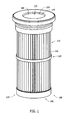
- FIG. 1 illustrates an example filtration system 100 that includes a filter cartridge 110 and a filter core 120 (shown, for example, in FIG. 2).
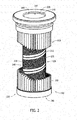
- FIGS. 2 and 3 are each partial cutaway views of filtration system 100.
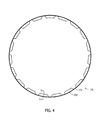
- FIG. 4 is a top view of filter core 120.
- filter core 120 is positioned to support filter cartridge 110.
- filtration system 100 is used in a pulse cleaning application. Alternatively, filtration system 100 may be used in any other filter cleaning application that enables filtration system 100 to function as described herein.
- filter cartridge 110 includes a sidewall 130 that defines a clean air channel 140 within filter cartridge 110.
- a plurality of pleats 150 extend radially outward from sidewall 130.
- pleats 150 are spaced substantially equidistantly circumferentially about sidewall 130.
- pleats 150 are fabricated from a filter media that enables fluid to be channeled through filtration system 100 to be purified.
- filter cartridge 110 or, more particularly, clean air channel 140 is sized to receive filter core 120 therein. More specifically, in the example embodiment, filter core 120 is positionable within filter channel 140 to facilitate supporting and/or restraining the filter media from excessive radially inward movement during forward flow in a first direction.
- a retainer 160 extends circumferentially about pleats 150 to facilitate aligning pleats 150.
- retainer 160 is fabricated from a thermoplastic polymer material that provides rigidity, strength, durability, and/or flexibility.
- retainer 160 limits radially outward movement of the filter media during reverse flow in a second direction.
- the thermoplastic polymer is substantially resistant to chemical attack, hydrolysis, and/or abrasion.
- retainer 160 may be fabricated from any other material that enables retainer 160 to function as described herein.
- filter core 120 is positioned within clean air channel 140.
- filter core 120 is fabricated from a rigid material, such as metal and/or plastic.
- the flat sheet may be fabricated from any material that enables filter core 120 to function as described herein.
- filter core 120 has a tubular body 170 that includes a first end 180 and a second end 190.
- tubular body 170 has a thickness that is between approximately 0.0090 inches (in.) and approximately 0.0179 in. More particularly, in the example embodiment, the thickness is between approximately 0.0105 in. and approximately 0.0149 in. Even more particularly, in the example embodiment, the thickness is approximately 0.0110 in.
- tubular body 170 may have any thickness that enables filter core 120 to function as described herein.
- tubular body 170 defines a cavity 200 that enables fluid to be channeled substantially longitudinally between first and second ends 180 and 190.
- first end 180 defines an opening 210 that enables fluid to be channeled into cavity 200
- second end 190 includes a pan 220 that seals second end 190 to facilitate preventing fluid flow from bypassing filter cartridge 110.
- first and/or second ends 180 and 190 may have any configuration that enables filtration system 100 to function as described herein.
- a plurality of surface features 230 are spaced substantially longitudinally along tubular body 170 between first and second ends 180 and 190.
- surface features 230 are arranged in a staggered array 240. More specifically, in the example embodiment, surface features 230 in array 240 are oriented substantially helically along at least a portion tubular body 170. Alternatively, surface features 230 may be arranged in any configuration and/or array 240 may extend over any portion of tubular body 170 that enables filter core 120 to function as described herein.
- each surface feature 230 at least partially defines at least one opening 250 (shown, for example, in FIG. 5 ) therein that enables fluid to be channeled between filter cartridge 110 and cavity 200. More specifically, as shown in FIGS. 4 and 5 , each surface feature 230 is formed as a scoop that protrudes radially inward from tubular body 170 and that is oriented to channel fluid in a substantially helical direction along tubular body 170. In the example embodiment, each surface feature 230 includes a first portion 260 for flow area and a second portion 270 for bridging across opening 250 for strength. That is, first portion 260 is configured to channel fluid in and out of filter core 120 through opening 250, and second portion 270 provides strength to surface feature 230.
- surface feature 230 is oriented such that opening 250 generally faces first end 180.
- surface feature 230 facilitates enhancing a fluid flow within filtration system 100. More specifically, surface feature 230 enables fluid to be channeled from a substantially radial direction to a substantially axial direction during forward flow, and from a substantially axial direction to a substantially radial direction during reverse flow.
- surface feature 230 may have any configuration and/or orientation that enables filter core 120 to function as described herein.
- fluid such as air
- fluid is channeled through filtration system 100 in a first or operating direction during forward flow to facilitate removing particulate matter, such as dust and/or debris, entrained in the fluid. More specifically, during forward flow, fluid is channeled from outside of filtration system 100, substantially radially inward through filter cartridge 110, substantially axially along a length of filter core 120, and discharged from first end opening 210. Over time, the particulate matter accumulates on the filter media.
- fluid is channeled through filtration system 100 in a second or cleaning direction during reverse flow to facilitate removing dust and/or debris from filter cartridge 110.
- a flow of compressed air and/or jet air is directed, such as pulsed, through first end opening 210 substantially axially toward second end 190 against the forward flow.
- the fluid is subsequently channeled substantially radially outward through openings 250 and toward filter cartridge 110, thus creating a shockwave and positive displacement that facilitates removing dust and/or debris from the filter media.
- FIG. 6 is a flowchart of an example method 300 that may be implemented to fabricate and/or assemble filter core 120.
- a flat strip or sheet is initially drawn 310 into a forming machine (not shown), and a seal form 312 (shown, for example, in FIG. 2 ) is formed 320 along an edge of the sheet.
- the sheet is formed at least partially from a steel material.
- the flat sheet may be fabricated from any material that enables filter core 120 to function as described herein.
- each surface features 230 are then formed 330 in an array 240, wherein each surface features 230 extends and protrudes from the sheet.
- the forming machine is used to form 330 surface features 230 in the sheet. More specifically, in the example embodiment, each surface feature 230 includes opening 250 that enables fluid to be channeled therethrough.
- the sheet is then formed 340 into a body, such as tubular body 170. More specifically, in the example embodiment, the sheet is rolled at an angle relative to a longitudinal axis of the sheet such that the sheet or, more particularly, seal form 312 and/or surface features 230 extend generally helically along at least a portion of tubular body 170 between first end 180 and second end 190. In the example embodiment, the sheet is rolled such that surface features 230 extend and/or protrude radially inward from tubular body 170 toward a center axis (not shown) of tubular body 170.
- the sheet edges are sealed 350 to form a lock seam such that fluid channeled radially into cavity 200 flows through surface feature openings 250.
- seal forms 312 enable the edges to be sealed 350.
- tubular body 170 is cut 360 to a predetermined length such that tubular body 170 is formed with at least one open end 180.
- the subject matter described herein facilitates reducing a thickness of a filter core, thereby decreasing a material cost associated with the fabrication and/or assembly of the filter core. More specifically, the subject matter described herein enables a filter core to be fabricated with a strength and/or stiffness that enables the filter core to be produced using thinner gauge metal sheets as compared to metal sheets used in fabricating conventional filter cores. Moreover, the subject matter described herein enables a filter cartridge to be effectively cleaned.
- Example embodiments of a filter core and methods of fabricating and/or assembling the same are described above in detail.
- the systems and methods are not limited to the specific embodiments described herein, but rather, components of systems and/or steps of the method may be utilized independently and separately from other components and/or steps described herein.
- Each component and each method step may also be used in combination with other components and/or method steps.
Landscapes
- Chemical & Material Sciences (AREA)
- Chemical Kinetics & Catalysis (AREA)
- Physics & Mathematics (AREA)
- Geometry (AREA)
- Filtering Of Dispersed Particles In Gases (AREA)
- Filtering Materials (AREA)
- Filtration Of Liquid (AREA)
Abstract
Description
- The present disclosure relates generally to filtration systems and, more particularly, to a filter core that may be used with a pleated filter cartridge.
- At least some known filtration systems include a filter cartridge that removes particulate matter, such as dust and/or debris, from fluid channeled through the filtration system. At least some known filtration systems include a filter core that is formed from a perforated and/or expanded sheet metal. Known filter cores formed from perforated and/or expanded sheet metal enable fluid to flow through perforations and/or slits at predetermined locations to clean an associated filter cartridge. Such known filter cores may be relatively weak due to the introduction of flow openings in the filter core.
- In one aspect, a filter core is provided for use with a filter cartridge. The filter core includes a tubular body having a first end and a second end. The tubular body includes a plurality of surface features spaced longitudinally along the tubular body between the first and second ends. Each of the surface features includes a first portion for flow area and a second portion for bridging across an opening for strength.
- In another aspect, a method is provided for fabricating a filter core for use with a filter cartridge. The method includes rolling a sheet to form a tubular body that has a first end and a second end. A plurality of surface features are formed spaced longitudinally along the tubular body between the first and second ends. Each of the surface features includes a first portion for flow area and a second portion for bridging across an opening for strength.
- In yet another aspect, a filtration system is provided. A filter cartridge includes a sidewall that defines a clean air channel. A filter core is sized to be positioned within the clean air channel. The filter core includes a tubular body having a first end and a second end. The tubular body includes a plurality of surface features spaced longitudinally along the tubular body between the first and second ends. Each of the surface features includes a first portion for flow area and a second portion for bridging across an opening for strength.
- The features, functions, and advantages described herein may be achieved independently in various embodiments of the present disclosure or may be combined in yet other embodiments, further details of which may be seen with reference to the following description and drawings.
-
-
FIG. 1 is a perspective view of an example filtration system; -
FIGS. 2 and3 are partial cutaway views of the filtration system shown inFIG. 1 ; -
FIG. 4 is a top view of an example filter core that may be used with the filtration system shown inFIG. 1 ; -
FIG. 5 is an enlarged cross-sectional view of an outer surface of the filter core shown inFIG. 4 ; and -
FIG. 6 is a flowchart of an example method that may be implemented to fabricate the filter core shown inFIG. 4 . - Although specific features of various embodiments may be shown in some drawings and not in others, this is for convenience only. Any feature of any drawing may be referenced and/or claimed in combination with any feature of any other drawing.
- The subject matter described herein relates generally to filtration systems and, more particularly, to a filter core that may be used with a pleated filter cartridge and a method for fabricating the same. The filter core may be used for any fluid (i.e., gas or liquid) filtration system that employs a reverse flow or bi-directional cleaning. As described herein, "forward flow" refers to a fluid flow in a conventional direction, "reverse flow" refers to a fluid flow in a direction that is opposite the conventional direction, and "bi-directional" refers to a selective fluid flow in either direction. In one embodiment, a filter core includes a tubular body having a first end and a second end. A plurality of surface features are spaced longitudinally along the body between the first and second ends. Each of the surface features includes a first portion for flow area and a second portion for bridging across an opening for strength. More specifically, the surface features are pushed radially inward from the tubular body, thus increasing a rigidity and/or strength of the tubular body. Accordingly, in such an embodiment, the surface features facilitate the use of thinner gauge sheet metal to form the tubular body as compared to conventional filter cores, thereby reducing a weight and/or a cost associated with the filtration system.
- As used herein, an element or step recited in the singular and proceeded with the word "a" or "an" should be understood as not excluding plural elements or steps unless such exclusion is explicitly recited. Furthermore, references to "one embodiment" of the present invention or the "example embodiment" are not intended to be interpreted as excluding the existence of additional embodiments that also incorporate the recited features.
-
FIG. 1 illustrates anexample filtration system 100 that includes afilter cartridge 110 and a filter core 120 (shown, for example, inFIG. 2). FIGS. 2 and3 are each partial cutaway views offiltration system 100.FIG. 4 is a top view offilter core 120. In the example embodiment,filter core 120 is positioned to supportfilter cartridge 110. In the example embodiment,filtration system 100 is used in a pulse cleaning application. Alternatively,filtration system 100 may be used in any other filter cleaning application that enablesfiltration system 100 to function as described herein. - In the example embodiment,
filter cartridge 110 includes asidewall 130 that defines aclean air channel 140 withinfilter cartridge 110. In the example embodiment, a plurality ofpleats 150 extend radially outward fromsidewall 130. Moreover, in the example embodiment,pleats 150 are spaced substantially equidistantly circumferentially aboutsidewall 130. In the example embodiment,pleats 150 are fabricated from a filter media that enables fluid to be channeled throughfiltration system 100 to be purified. - In the example embodiment,
filter cartridge 110 or, more particularly,clean air channel 140 is sized to receivefilter core 120 therein. More specifically, in the example embodiment,filter core 120 is positionable withinfilter channel 140 to facilitate supporting and/or restraining the filter media from excessive radially inward movement during forward flow in a first direction. - In the example embodiment, a
retainer 160 extends circumferentially aboutpleats 150 to facilitate aligningpleats 150. In the example embodiment,retainer 160 is fabricated from a thermoplastic polymer material that provides rigidity, strength, durability, and/or flexibility. In the example embodiment,retainer 160 limits radially outward movement of the filter media during reverse flow in a second direction. Moreover, in the example embodiment, the thermoplastic polymer is substantially resistant to chemical attack, hydrolysis, and/or abrasion. Alternatively,retainer 160 may be fabricated from any other material that enablesretainer 160 to function as described herein. - In the example embodiment,
filter core 120 is positioned withinclean air channel 140. In the example embodiment,filter core 120 is fabricated from a rigid material, such as metal and/or plastic. Alternatively, the flat sheet may be fabricated from any material that enablesfilter core 120 to function as described herein. - In the example embodiment,
filter core 120 has atubular body 170 that includes afirst end 180 and asecond end 190. In the example embodiment,tubular body 170 has a thickness that is between approximately 0.0090 inches (in.) and approximately 0.0179 in. More particularly, in the example embodiment, the thickness is between approximately 0.0105 in. and approximately 0.0149 in. Even more particularly, in the example embodiment, the thickness is approximately 0.0110 in. Alternatively,tubular body 170 may have any thickness that enablesfilter core 120 to function as described herein. - In the example embodiment,
tubular body 170 defines acavity 200 that enables fluid to be channeled substantially longitudinally between first and second ends 180 and 190. In the example embodiment,first end 180 defines anopening 210 that enables fluid to be channeled intocavity 200, andsecond end 190 includes apan 220 that sealssecond end 190 to facilitate preventing fluid flow from bypassingfilter cartridge 110. Alternatively, first and/or second ends 180 and 190 may have any configuration that enablesfiltration system 100 to function as described herein. - In the example embodiment, a plurality of surface features 230 (shown, for example, in
FIG. 2 ) are spaced substantially longitudinally alongtubular body 170 between first and second ends 180 and 190. In the example embodiment, surface features 230 are arranged in astaggered array 240. More specifically, in the example embodiment, surface features 230 inarray 240 are oriented substantially helically along at least aportion tubular body 170. Alternatively, surface features 230 may be arranged in any configuration and/orarray 240 may extend over any portion oftubular body 170 that enablesfilter core 120 to function as described herein. - In the example embodiment, each
surface feature 230 at least partially defines at least one opening 250 (shown, for example, inFIG. 5 ) therein that enables fluid to be channeled betweenfilter cartridge 110 andcavity 200. More specifically, as shown inFIGS. 4 and5 , eachsurface feature 230 is formed as a scoop that protrudes radially inward fromtubular body 170 and that is oriented to channel fluid in a substantially helical direction alongtubular body 170. In the example embodiment, eachsurface feature 230 includes a first portion 260 for flow area and a second portion 270 for bridging across opening 250 for strength. That is, first portion 260 is configured to channel fluid in and out offilter core 120 throughopening 250, and second portion 270 provides strength tosurface feature 230. - In the example embodiment,
surface feature 230 is oriented such thatopening 250 generally facesfirst end 180. As such, in the example embodiment,surface feature 230 facilitates enhancing a fluid flow withinfiltration system 100. More specifically,surface feature 230 enables fluid to be channeled from a substantially radial direction to a substantially axial direction during forward flow, and from a substantially axial direction to a substantially radial direction during reverse flow. Alternatively,surface feature 230 may have any configuration and/or orientation that enablesfilter core 120 to function as described herein. - During operation, fluid, such as air, is channeled through
filtration system 100 in a first or operating direction during forward flow to facilitate removing particulate matter, such as dust and/or debris, entrained in the fluid. More specifically, during forward flow, fluid is channeled from outside offiltration system 100, substantially radially inward throughfilter cartridge 110, substantially axially along a length offilter core 120, and discharged fromfirst end opening 210. Over time, the particulate matter accumulates on the filter media. - To facilitate cleaning
filter cartridge 110, in the example embodiment, fluid is channeled throughfiltration system 100 in a second or cleaning direction during reverse flow to facilitate removing dust and/or debris fromfilter cartridge 110. More specifically, in the example embodiment, a flow of compressed air and/or jet air is directed, such as pulsed, through first end opening 210 substantially axially towardsecond end 190 against the forward flow. In the example embodiment, the fluid is subsequently channeled substantially radially outward throughopenings 250 and towardfilter cartridge 110, thus creating a shockwave and positive displacement that facilitates removing dust and/or debris from the filter media. -
FIG. 6 is a flowchart of an example method 300 that may be implemented to fabricate and/or assemblefilter core 120. In the example embodiment, a flat strip or sheet is initially drawn 310 into a forming machine (not shown), and a seal form 312 (shown, for example, inFIG. 2 ) is formed 320 along an edge of the sheet. In the example embodiment, the sheet is formed at least partially from a steel material. Alternatively, the flat sheet may be fabricated from any material that enablesfilter core 120 to function as described herein. - In the example embodiment, surface features 230 are then formed 330 in an
array 240, wherein each surface features 230 extends and protrudes from the sheet. In the example embodiment, the forming machine is used to form 330 surface features 230 in the sheet. More specifically, in the example embodiment, eachsurface feature 230 includes opening 250 that enables fluid to be channeled therethrough. - In the example embodiment, the sheet is then formed 340 into a body, such as
tubular body 170. More specifically, in the example embodiment, the sheet is rolled at an angle relative to a longitudinal axis of the sheet such that the sheet or, more particularly,seal form 312 and/or surface features 230 extend generally helically along at least a portion oftubular body 170 betweenfirst end 180 andsecond end 190. In the example embodiment, the sheet is rolled such that surface features 230 extend and/or protrude radially inward fromtubular body 170 toward a center axis (not shown) oftubular body 170. - In the example embodiment, the sheet edges are sealed 350 to form a lock seam such that fluid channeled radially into
cavity 200 flows throughsurface feature openings 250. In the example embodiment, seal forms 312 enable the edges to be sealed 350. Moreover, in the example embodiment,tubular body 170 is cut 360 to a predetermined length such thattubular body 170 is formed with at least oneopen end 180. - The subject matter described herein facilitates reducing a thickness of a filter core, thereby decreasing a material cost associated with the fabrication and/or assembly of the filter core. More specifically, the subject matter described herein enables a filter core to be fabricated with a strength and/or stiffness that enables the filter core to be produced using thinner gauge metal sheets as compared to metal sheets used in fabricating conventional filter cores. Moreover, the subject matter described herein enables a filter cartridge to be effectively cleaned.
- Example embodiments of a filter core and methods of fabricating and/or assembling the same are described above in detail. The systems and methods are not limited to the specific embodiments described herein, but rather, components of systems and/or steps of the method may be utilized independently and separately from other components and/or steps described herein. Each component and each method step may also be used in combination with other components and/or method steps. Although specific features of various embodiments may be shown in some drawings and not in others, this is for convenience only. Any feature of a drawing may be referenced and/or claimed in combination with any feature of any other drawing.
- This written description uses examples to disclose the embodiments, including the best mode, and also to enable any person skilled in the art to practice the embodiments, including making and using any devices or systems and performing any incorporated methods. The patentable scope of the disclosure is defined by the claims, and may include other examples that occur to those skilled in the art. Such other examples are intended to be within the scope of the claims if they have structural elements that do not differ from the literal language of the claims, or if they include equivalent structural elements with insubstantial differences from the literal language of th claims.
Claims (15)
- A filter core (120) for use with a filter cartridge (110), said filter core comprising a tubular body (170) having a first end (180) and a second end (190), wherein said tubular body comprises a plurality of surface features (230) spaced longitudinally along said tubular body between said first and second ends, each of said plurality of surface features comprising a first portion (260) for flow area and a second portion (270) for bridging across an opening for strength.
- A filter core in accordance with Claim 1, wherein each of said plurality of surface features extends radially inward from said tubular body towards a center axis of said filter core.
- A filter core in accordance with Claim 1 or Claim 2, wherein said plurality of surface features are oriented generally helically across at least a portion of said tubular body.
- A filter core in accordance with Claim 1, 2 or 3, wherein said plurality of surface features are arranged in a predefined array (240) that is oriented generally helically across at least a portion of said tubular body.
- A filter core in accordance with any preceding Claim, wherein each of said plurality of surface features includes an opening (250) defmed therein, each of said opening oriented to channel fluid therethrough.
- A filter core in accordance with any preceding Claim, wherein said plurality of surface features comprise a plurality of scoops that are disposed to enhance a fluid flow.
- A filter core in accordance with any preceding Claim, wherein at least one of said first end and said second end defines an opening (210) that enables fluid to be channeled therethrough.
- A filtration system (100) comprising:a filter cartridge (110) including a sidewall (130) that defines a clean air channel (140); anda filter core (120) in accordance with any one of Claims 1 to 7.
- A filtration system in accordance with Claim 8, wherein said filter cartridge (110) comprises a plurality of pleats extending radially outward from said sidewall (130).
- A method of fabricating a filter core (120) for use with a filter cartridge (110), said method comprising:forming a plurality of surface features (230) spaced longitudinally along a sheet, each of the plurality of surface features including a first portion for flow area and a second portion for bridging across an opening for strength; androlling the sheet to form a tubular body (170) that has a first end (180) and a second end (190) such that the plurality of surface features are spaced longitudinally along the tubular body between the first end and the second end.
- A method in accordance with Claim 10, wherein rolling the sheet further comprises orienting the plurality of surface features (230) such that each of the plurality of surface features extends radially inward from the tubular body towards a center axis of the filter core.
- A method in accordance with Claim 10 or Claim 11, wherein rolling the sheet further comprises orienting the plurality of surface features (230) such that the plurality of surface features are oriented generally helically across at least a portion the tubular body.
- A method in accordance with Claim 10, 11 or 12, wherein forming a plurality of surface features further comprises forming the plurality of surface features (230) such that the plurality of surface features are arranged in a predefined array (240).
- A method in accordance with any one of Claims 10 to 13, wherein forming a plurality of surface features further comprises forming the plurality of surface features (230) such that each of the plurality of surface features includes an opening (250) defined therein, each of the openings oriented to channel fluid therethrough.
- A method in accordance with any one of Claims 10 to 14, wherein rolling the sheet to form a tubular body (170) further comprises rolling the sheet such that at least one of the first end (180) and the second end (190) defines an opening (210) that enables fluid to be channeled therethrough.
Applications Claiming Priority (1)
| Application Number | Priority Date | Filing Date | Title |
|---|---|---|---|
| US13/212,243 US8523974B2 (en) | 2011-08-18 | 2011-08-18 | Filter core for use with pleated filter cartridges |
Publications (2)
| Publication Number | Publication Date |
|---|---|
| EP2559471A2 true EP2559471A2 (en) | 2013-02-20 |
| EP2559471A3 EP2559471A3 (en) | 2016-12-07 |
Family
ID=46679211
Family Applications (1)
| Application Number | Title | Priority Date | Filing Date |
|---|---|---|---|
| EP12180639.2A Withdrawn EP2559471A3 (en) | 2011-08-18 | 2012-08-16 | Filter core for use with pleated filter cartridges |
Country Status (5)
| Country | Link |
|---|---|
| US (1) | US8523974B2 (en) |
| EP (1) | EP2559471A3 (en) |
| JP (1) | JP2013039557A (en) |
| KR (1) | KR102000291B1 (en) |
| CN (1) | CN102949903A (en) |
Cited By (2)
| Publication number | Priority date | Publication date | Assignee | Title |
|---|---|---|---|---|
| EP3068512A4 (en) * | 2013-11-13 | 2016-11-02 | Delstar Technologies Inc | Cartridge filter |
| EP4417288A1 (en) | 2023-02-17 | 2024-08-21 | Filtration Group GmbH | Ring filter element |
Families Citing this family (9)
| Publication number | Priority date | Publication date | Assignee | Title |
|---|---|---|---|---|
| US9868083B2 (en) * | 2014-06-24 | 2018-01-16 | Robovent Products Group, Inc. | Filter media cartridge |
| US9868627B2 (en) * | 2015-02-19 | 2018-01-16 | Paul BATISTAKIS | Combination spout and filter, particularly for paint barrels |
| KR101725798B1 (en) * | 2015-05-11 | 2017-04-11 | 신대건 | Large Sized Cartridge Filter and Method for Manufacturing Using the Same |
| CN106268085B (en) * | 2015-05-11 | 2018-02-09 | (株)大韩Pnc | Pleated filter and its manufacture method |
| CN107847845B (en) * | 2015-06-08 | 2020-07-14 | 美国圣戈班性能塑料公司 | High pressure filter |
| EP3423166B1 (en) * | 2016-03-02 | 2020-01-01 | Donaldson Company, Inc. | Filter element having inner support and method of filtering |
| KR20180067064A (en) * | 2016-12-12 | 2018-06-20 | 최태국 | Water treatment filter manufacturing apparatus and filter |
| CA3044946C (en) | 2018-09-17 | 2025-10-07 | McFarlen Engineering Ltd. | Filter support element and method of using same |
| US12161956B2 (en) | 2020-09-21 | 2024-12-10 | Donaldson Company, Inc. | Filter cartridge, filter assembly, and methods |
Family Cites Families (24)
| Publication number | Priority date | Publication date | Assignee | Title |
|---|---|---|---|---|
| US2732026A (en) * | 1956-01-24 | Muffler with flashing and spark | ||
| US1779458A (en) * | 1926-10-18 | 1930-10-28 | Harry C Chappell | Air filter |
| US3724670A (en) * | 1971-02-12 | 1973-04-03 | Fram Corp | Separating fluids |
| US3737281A (en) * | 1971-09-27 | 1973-06-05 | C Guth | Fuel mixing shroud for heating torches |
| JPS5621459Y2 (en) * | 1976-04-01 | 1981-05-21 | ||
| CA1069001A (en) * | 1976-09-03 | 1980-01-01 | Frederick E. Schuler | Air cleaner with integral louvered precleaner |
| JPS5620011Y2 (en) * | 1979-05-21 | 1981-05-13 | ||
| GB2088421A (en) * | 1980-11-28 | 1982-06-09 | Harrop Robert Anthony | Perforated sheet material and tubes for fluid filters |
| US4842739A (en) * | 1987-08-20 | 1989-06-27 | Minnesota Mining And Manufacturing Company | High surface area filter cartridge |
| US5207812B1 (en) | 1992-05-08 | 1996-10-01 | Gore & Ass | Filter cartridge |
| US5384044A (en) * | 1993-09-07 | 1995-01-24 | Techniweave, Inc. | Fluid separation devices and methods of making same |
| US6726735B1 (en) | 1994-05-06 | 2004-04-27 | Bha Group Holdings, Inc. | Unitary filter cartridge |
| US5632791A (en) | 1994-12-06 | 1997-05-27 | Bha Group, Inc. | Unitary filter cartridge |
| US5490930A (en) * | 1994-09-27 | 1996-02-13 | Baldwin Filters, Inc. | Filter |
| US5961678A (en) * | 1995-07-07 | 1999-10-05 | Flair Corporation | Filter drainage layer attachment |
| DE10063881A1 (en) * | 2000-12-21 | 2002-06-27 | Mann & Hummel Filter | filter element |
| US20030155293A1 (en) * | 2002-02-21 | 2003-08-21 | Mcgrath James A. | Square-holed spiral welded filter element support sleeve |
| AU2003220090A1 (en) * | 2002-03-08 | 2003-09-22 | Donaldson Company, Inc. | Liquid filter arrangement with secondary filter and bypass flow |
| JP4358538B2 (en) * | 2003-03-17 | 2009-11-04 | 日本碍子株式会社 | Ceramic filter |
| JP2007527785A (en) * | 2004-03-05 | 2007-10-04 | ドナルドソン カンパニー,インコーポレイティド | Liquid filter assembly for use with a treating agent and method of using the same |
| CA2728613C (en) * | 2004-12-29 | 2015-06-09 | Baldwin Filters, Inc. | Filter canister with locking base plate |
| FR2883487B1 (en) * | 2005-03-25 | 2008-02-22 | Fleetguard Snc | HOLLOW ELEMENT FOR THE SUPPORT OF A FILTRATION MEDIUM, INCLUDING MEANS OF SUPPORT IN THE FORM OF SUBSTANTIALLY CONSTANT SLOPE SPIRAL PORTIONS, AND CORRESPONDING FILTER ASSEMBLY |
| KR200419235Y1 (en) * | 2006-03-30 | 2006-06-19 | 주식회사 삼우필터 | LNG supply line filter |
| US20070261377A1 (en) * | 2006-05-10 | 2007-11-15 | Klug Jerry J | Spin-on filter arrangement and methods |
-
2011
- 2011-08-18 US US13/212,243 patent/US8523974B2/en active Active
-
2012
- 2012-08-08 JP JP2012175497A patent/JP2013039557A/en active Pending
- 2012-08-16 EP EP12180639.2A patent/EP2559471A3/en not_active Withdrawn
- 2012-08-16 KR KR1020120089574A patent/KR102000291B1/en not_active Expired - Fee Related
- 2012-08-17 CN CN2012102939161A patent/CN102949903A/en active Pending
Non-Patent Citations (1)
| Title |
|---|
| None |
Cited By (4)
| Publication number | Priority date | Publication date | Assignee | Title |
|---|---|---|---|---|
| EP3068512A4 (en) * | 2013-11-13 | 2016-11-02 | Delstar Technologies Inc | Cartridge filter |
| EP4417288A1 (en) | 2023-02-17 | 2024-08-21 | Filtration Group GmbH | Ring filter element |
| DE102023201391A1 (en) * | 2023-02-17 | 2024-08-22 | Filtration Group Gmbh | Ring filter element |
| DE102023201391B4 (en) * | 2023-02-17 | 2025-10-02 | Filtration Group Gmbh | Ring filter element |
Also Published As
| Publication number | Publication date |
|---|---|
| US20130042585A1 (en) | 2013-02-21 |
| JP2013039557A (en) | 2013-02-28 |
| US8523974B2 (en) | 2013-09-03 |
| KR102000291B1 (en) | 2019-07-15 |
| KR20130020606A (en) | 2013-02-27 |
| EP2559471A3 (en) | 2016-12-07 |
| CN102949903A (en) | 2013-03-06 |
Similar Documents
| Publication | Publication Date | Title |
|---|---|---|
| US8523974B2 (en) | Filter core for use with pleated filter cartridges | |
| US20230321582A1 (en) | Ovate tubular filter cartridges and filter systems using the same | |
| US8137427B2 (en) | Filter element with pleat support combs | |
| US8540805B2 (en) | Filter assembly for use in a turbine system | |
| US20100252495A1 (en) | Filter Structure | |
| US20080272048A1 (en) | Filter cartridge media retention system | |
| EP3978096A1 (en) | Air filter element | |
| WO2007084645A2 (en) | Method and apparatus for reinforcing a sealing collar | |
| EP2678089A2 (en) | Extended area filter with internal support structures | |
| WO2015179800A1 (en) | Forming filtration media for maintaining flow passage through a sock style filter | |
| DE202009003704U1 (en) | Filter element and support body for such a filter element | |
| US8409317B2 (en) | Filter assembly with housing structure | |
| EP2409749A1 (en) | Coreless filter cartridge and method of forming a coreless filter cartridge | |
| JPH067621A (en) | Air cleaner element | |
| JP4867859B2 (en) | Pressure sensor hose | |
| US9868083B2 (en) | Filter media cartridge | |
| JP3308968B2 (en) | Air filter for internal combustion engine | |
| EP4034283B1 (en) | Star pleating with inside out flow having water drainage through the center | |
| JP2009297666A (en) | Pleat-like air filter and its manufacturing method | |
| JP6799770B2 (en) | Cartridge type filter element for industrial dust collector | |
| JP2010510043A (en) | Manufacturing method of support and filter element | |
| JP2010510043A6 (en) | Manufacturing method of support and filter element |
Legal Events
| Date | Code | Title | Description |
|---|---|---|---|
| PUAI | Public reference made under article 153(3) epc to a published international application that has entered the european phase |
Free format text: ORIGINAL CODE: 0009012 |
|
| AK | Designated contracting states |
Kind code of ref document: A2 Designated state(s): AL AT BE BG CH CY CZ DE DK EE ES FI FR GB GR HR HU IE IS IT LI LT LU LV MC MK MT NL NO PL PT RO RS SE SI SK SM TR |
|
| AX | Request for extension of the european patent |
Extension state: BA ME |
|
| RAP1 | Party data changed (applicant data changed or rights of an application transferred) |
Owner name: BHA ALTAIR, LLC |
|
| PUAL | Search report despatched |
Free format text: ORIGINAL CODE: 0009013 |
|
| AK | Designated contracting states |
Kind code of ref document: A3 Designated state(s): AL AT BE BG CH CY CZ DE DK EE ES FI FR GB GR HR HU IE IS IT LI LT LU LV MC MK MT NL NO PL PT RO RS SE SI SK SM TR |
|
| AX | Request for extension of the european patent |
Extension state: BA ME |
|
| RIC1 | Information provided on ipc code assigned before grant |
Ipc: B01D 46/00 20060101ALI20161101BHEP Ipc: B01D 46/52 20060101ALI20161101BHEP Ipc: B01D 46/24 20060101AFI20161101BHEP Ipc: B01D 29/21 20060101ALI20161101BHEP Ipc: B01D 29/11 20060101ALI20161101BHEP |
|
| 17P | Request for examination filed |
Effective date: 20170606 |
|
| RBV | Designated contracting states (corrected) |
Designated state(s): AL AT BE BG CH CY CZ DE DK EE ES FI FR GB GR HR HU IE IS IT LI LT LU LV MC MK MT NL NO PL PT RO RS SE SI SK SM TR |
|
| 17Q | First examination report despatched |
Effective date: 20190717 |
|
| STAA | Information on the status of an ep patent application or granted ep patent |
Free format text: STATUS: THE APPLICATION IS DEEMED TO BE WITHDRAWN |
|
| 18D | Application deemed to be withdrawn |
Effective date: 20191128 |