EP2558663B1 - Door handle - Google Patents
Door handle Download PDFInfo
- Publication number
- EP2558663B1 EP2558663B1 EP11716615.7A EP11716615A EP2558663B1 EP 2558663 B1 EP2558663 B1 EP 2558663B1 EP 11716615 A EP11716615 A EP 11716615A EP 2558663 B1 EP2558663 B1 EP 2558663B1
- Authority
- EP
- European Patent Office
- Prior art keywords
- liquid
- door handle
- gel
- grip
- reservoir
- Prior art date
- Legal status (The legal status is an assumption and is not a legal conclusion. Google has not performed a legal analysis and makes no representation as to the accuracy of the status listed.)
- Not-in-force
Links
Images











Classifications
-
- E—FIXED CONSTRUCTIONS
- E05—LOCKS; KEYS; WINDOW OR DOOR FITTINGS; SAFES
- E05B—LOCKS; ACCESSORIES THEREFOR; HANDCUFFS
- E05B1/00—Knobs or handles for wings; Knobs, handles, or press buttons for locks or latches on wings
- E05B1/0069—Sanitary doorknobs or handles, e.g. comprising a disinfectant
-
- A—HUMAN NECESSITIES
- A61—MEDICAL OR VETERINARY SCIENCE; HYGIENE
- A61L—METHODS OR APPARATUS FOR STERILISING MATERIALS OR OBJECTS IN GENERAL; DISINFECTION, STERILISATION OR DEODORISATION OF AIR; CHEMICAL ASPECTS OF BANDAGES, DRESSINGS, ABSORBENT PADS OR SURGICAL ARTICLES; MATERIALS FOR BANDAGES, DRESSINGS, ABSORBENT PADS OR SURGICAL ARTICLES
- A61L2/00—Disinfection or sterilisation of materials or objects, in general; Accessories therefor
- A61L2/02—Disinfection or sterilisation of materials or objects, in general; Accessories therefor using physical processes
- A61L2/08—Radiation
- A61L2/10—Ultraviolet [UV] radiation
-
- A—HUMAN NECESSITIES
- A61—MEDICAL OR VETERINARY SCIENCE; HYGIENE
- A61L—METHODS OR APPARATUS FOR STERILISING MATERIALS OR OBJECTS IN GENERAL; DISINFECTION, STERILISATION OR DEODORISATION OF AIR; CHEMICAL ASPECTS OF BANDAGES, DRESSINGS, ABSORBENT PADS OR SURGICAL ARTICLES; MATERIALS FOR BANDAGES, DRESSINGS, ABSORBENT PADS OR SURGICAL ARTICLES
- A61L2/00—Disinfection or sterilisation of materials or objects, in general; Accessories therefor
- A61L2/16—Disinfection or sterilisation of materials or objects, in general; Accessories therefor using chemical substances
- A61L2/18—Liquid substances
-
- B—PERFORMING OPERATIONS; TRANSPORTING
- B65—CONVEYING; PACKING; STORING; HANDLING THIN OR FILAMENTARY MATERIAL
- B65D—CONTAINERS FOR STORAGE OR TRANSPORT OF ARTICLES OR MATERIALS, e.g. BAGS, BARRELS, BOTTLES, BOXES, CANS, CARTONS, CRATES, DRUMS, JARS, TANKS, HOPPERS, FORWARDING CONTAINERS; ACCESSORIES, CLOSURES, OR FITTINGS THEREFOR; PACKAGING ELEMENTS; PACKAGES
- B65D83/00—Containers or packages with special means for dispensing contents
- B65D83/14—Containers for dispensing liquid or semi-liquid contents by internal gaseous pressure, i.e. aerosol containers comprising propellant
- B65D83/16—Actuating means
- B65D83/26—Actuating means operating automatically, e.g. periodically
- B65D83/267—Actuating means operating automatically, e.g. periodically by a separate device actuated by repeated, e.g. human, input, e.g. by a moving wing of a door or window, a ringing doorbell, a flushing toilet
-
- E—FIXED CONSTRUCTIONS
- E05—LOCKS; KEYS; WINDOW OR DOOR FITTINGS; SAFES
- E05B—LOCKS; ACCESSORIES THEREFOR; HANDCUFFS
- E05B63/00—Locks or fastenings with special structural characteristics
- E05B63/0056—Locks with adjustable or exchangeable lock parts
Definitions
- the present invention relates to a door handle adapted to apply liquid or gel to a user's hand.
- Application of disinfectant gel to users' hands is recognised to improve cleanliness and control spread of infection, particularly in public buildings such as schools and hospitals.
- self standing or wall mounted disinfectant sprays or pumps are fitted at door ways to allow a user to apply the disinfectant before entering a building or entering a room within the building.
- an alternative approach is needed.
- a known approach is to provide a door handle that applies a disinfectant in the form of a liquid or gel to a user's hand.
- Known door handles for applying liquid or gel to a user's hand fall within two designs.
- a door handle is fitted with a pump arrangement, typically in the form of a piston, see reference documents [1, 2, 3].
- the pump is in fluid communication with a reservoir containing the disinfectant liquid or gel.
- the pump is also coupled to the door handle and the door, such that the rotary action of the door handle being turned by a user to open the door actuates the pump.
- the disinfectant is applied to a surface of the door handle.
- a similar pump device has also been applied to a pull-handle, see reference document [1].
- the pull-handle is mounted to a door using mounting points that allow the handle to move with respect to the mounting points when the door handle is pulled to open the door.
- a pump arrangement is fitted within the door handle and coupled between the mounting points and the door handle. When the door is opened, the door handle moves with respect to its mounting points, such that the disinfectant is pumped from a reservoir coupled to the pump and onto a surface of the door handle.
- the door handle is provided with a grip that is provided with a disinfectant gel or liquid.
- the disinfectant gel or liquid may be supplied from a reservoir.
- the grip may include a porous cover, see reference documents [4, 5, 6] or the handle may be provided with an absorbent material within a hollow grip, such that he absorbent martial is exposed through holes in the hollow grip, see reference documents [5, 7].
- the grip may include a plastic shroud having a fluid outlet in the form of a flap, such that when the door handle is gripped the cover is deformed to open the flap, see reference document [8].
- the object of the present invention is to provide an improved disinfectant liquid or gel applying door handle.
- a door handle adapted to apply liquid or gel (liquid/gel) to a user's hand, the handle comprising:
- reservoir could be arranged in use below the displacement device, with the liquid/gel being sucked up from it, normally the use position of the reservoir will be above the grip with gravity assisting or causing the liquid/gel to flow down and.
- the displacement device could be a piston and cylinder device, or a diaphragm and chamber device, which devices would normally be expected to require a return spring for the cylinder or chamber and the trigger, preferably, the displacement device is a resilient device of elastomeric material adapted to return from its shape after displacement of liquid or gel to its original shape for replenishing the displacement device.
- the trigger is provided with a plurality of liquid/gel outlets which are normally closed and are individually opened by digital pressure on them, whereby the liquid or gel is expelled selectively where the digits act against the trigger.
- each ball is urged into its outlet by a respective spring.
- the springs can be coil springs or leaf springs in the form of tabs bent from a single strip.
- the balls can be replaced by closure members integrally moulded to resilient fingers, which urge their closure members into the outlets.
- the door handle may comprise a second grip adapted to provide a physical antibacterial action to complement the liquid/gel of the first grip which provides a chemical antibacterial action.
- the second grip may have a surface made of a material with an antibacterial action, or the second grip may incorporate an ultraviolet (UV) light source adapted to radiate UV light from inside the second grip to a UV-transparent outer surface of the grip, thereby providing an antibacterial action.
- UV ultraviolet
- the first grip may extend vertically and the second grip may extend vertically and the second grip may be arranged below and in line with the first grip.
- the door handle may comprise a guard member arranged to protect the reservoir from impact, if a door on which the handle is mounted is opened and brought into contact with an adjacent wall.
- the door handle may comprise a second, upper liquid/gel reservoir removably mounted on the handle which, when fitted, is in fluid communication with the lower liquid/gel reservoir by virtue of an aperture of the upper liquid/gel reservoir engaging with an aperture of the lower liquid/gel reservoir.
- the lower liquid/gel reservoir may have a flap that is arranged to be movable between a closed position and an open position, wherein absent actuation and when the upper liquid/gel reservoir is not fitted the flap adopts the closed position in which the flap forms a closure over the aperture in the lower liquid/gel reservoir and wherein fitment of the upper liquid/gel reservoir to the handle urges the flap into its open position which allows liquid/gel transfer from the upper liquid/gel reservoir to the lower liquid/gel reservoir.
- the lower liquid/gel reservoir may comprise a vent element arranged in an upper surface portion thereof, which is connected to the flap, such that when the flap is in the closed position the vent is closed and when the flap is in the open position the vent is open to facilitate filling of the lower liquid/gel reservoir with liquid/gel from the upper liquid/gel reservoir.
- the lower liquid/gel reservoir may have an integral visual level indicator or may comprise a light arranged to illuminate at least one of the upper and lower liquid/gel reservoirs and a switch arranged to be actuated by fitment of the upper liquid/gel reservoir and thereby turn on the light.
- a door to which is fitted a door handle according to the invention.
- the door handle comprises a first and second grip
- the first grip may be arranged at an optimum height for door actuation by an adult so that the second grip is lower, thereby through ergonomics making it more likely that a user will open the door using the first grip.
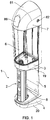
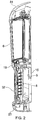
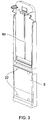
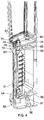
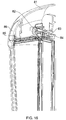
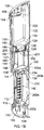
- Figures 1 to 16 illustrate a door handle according to a first embodiment of the invention.
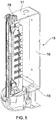
- a door handle 1 has a grip 2 connected via two brackets 3, 4 to a door plate 5 fast in use with a door (not shown). Above the grip is arranged a disinfectant gel reservoir 6. The door plate 5 extends up to a further bracket 7. A trigger 8 on the door side of the grip is displaceable towards the grip to dispense disinfectant gel from reservoir onto digits of a hand pulling on the grip.
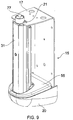
- Figures 1 to 16 are CAD drawings, with views chosen to illustrate particular features. It is suggested that if a feature cannot be found quickly in one Figure, the others should be referred to.
- the grip 2 is based on an extrusion 11, having two bores 12 in its sidewalls 14. It is fixed to the door via a sheet metal pressing 15, having a central web 16 against the door in use and upper and lower flanges 17,18 within plastics material mouldings 19,20. The latter give the impression of being brackets 3,4, although they are in reality covers. Screws 21 passing through the flanges engage in the bores 12 for fastening the extrusion 11 to the pressing.
- the door plate 5 is a single moulding extending the height of the handle and having apertures 22 aligned with apertures in the web of the pressing for screws (not shown) to fix the handle to the door.
- the screws fasten the pressing 15, by acting via the door plate.
- the extrusion 11 has a front wall 31, albeit covered with a decorative strip 32.
- a static pressure plate 34 for a tubular resilient vessel 35.
- a moving pressure plate 36 against which the trigger 8 bears.
- the trigger has lips 37 which pass around the outside of lips 38 of the extrusion 11, thus locating the trigger laterally whilst allowing it to be moved towards the extrusion.
- the trigger bears at longitudinal strips 39 against steps 40 on the moving pressure plate.
- the trigger and the moving pressure plate define a void 42.
- the trigger plate In its face 43 facing the door plate 5, the trigger plate has an array of apertures 44, each normally closed by a ball 45, the balls being held into seats 46 internally of the apertures by springs 47 bearing against the bottoms of blind sockets 48 in the pressure plate.
- the lower end of the trigger and moving pressure plate assembly 36/8 has tangs 54 which engage in a secondary lower moulding 55 on the top side of the lower flange 18, whereas the moulding 20 covers the underside of the flange. These two mouldings are held to the flange by a screw 56.
- the moulding 55 has a recess 57 in which the tangs engage, restricting the assembly 36/8 from moving freely backwards out of engagement with the extrusion 11.
- the moulding 55 has a drain 58 for allowing any excess gel to run down into the bottom moulding 20, which is dish-shaped to collect it. Periodically, on filling of the reservoir, the screw and the bottom moulding can be removed for cleaning out of any such collected gel.
- the upper cover moulding 19 is fitted below the upper flange 17 and restricts the upper end of the assembly 36/8 in similar manner, by engagement of tangs 59 in a recess 60.
- the top end of the decorative strip 32 engages a lower rim 61 of the cover moulding, with the rim passing on round the extrusion 11 to contain the tangs.
- the moulding has two bosses 62 into which screws (not shown) pass down through the upper flange 17 to secure the moulding. Also two cruciform spigots 63 of the moulding engage in apertures 64 in the upper flange.
- the upper end of the extrusion 11 has an adapter moulding 65 engaged in it. It is captivated by the upper screws 21 passing through it via a lip 66 that engages underneath the flange 17.
- the adapter On its underside, the adapter carries a hollow boss 67 onto which the top end of the resilient vessel 35 fits.
- the adapter On its top side and passing through the flange 17, the adapter has another hollow boss 68, with a central spigot 69.
- the reservoir has a smaller depending open boss 71, with two further closed bosses 72, which engage the cruciform spigots 63 extending through the flange 17.
- the open boss receives an insert 74, with an out-turned lip 75. This captivates an O-ring 76. The latter seals the boss 71 in the boss 68.
- the insert also loosely captivates a non-return valve ball 77, at a tapered seat 78.
- the ball engages the seat 78 and closes the boss 71 against out flow of gel.
- the spigot 69 lifts the ball off the seat 78.
- the boss 71 has a complementary, oppositely facing seat 79, against which the ball is lifted to act in a non-return valve manner against return flow on gripping of the handle and movement of the trigger into the extrusion 11.
- the gel in the vessel 35 is displaced out at the trigger.
- the vessel recovers its shape.
- the balls 45 seal the trigger against ingress of air under action of their springs and the vessel is refilled.
- the balls are arranged against their seats in a manner such as to prevent egress of gel except when they are pressed in. They are not arranged as non-return valves complementary the non-return valve 53 such that, if the trigger were pressed in without pressure on any of the balls, gel would flow at all the balls.
- a top moulding 81 which appears to be a bracket in the same way that mouldings 19, 20 appear to be brackets 3,4, is provided to captivate the reservoir in its use position. It has a rotary latch 82. This and the top end of the door plate have complementary formations 83, 84 for locking the top moulding in position.
- the moulding has a filler port 85 and a bung 86 for topping up of the reservoir with gel without its removal from the handle.
- the reservoir has rear rib 87, which engages in a slot 88 in the door plate for lateral location of the reservoir.
- FIG 17 illustrates schematically a door handle 100 according to a second embodiment of the invention.
- the elements of the door handle are manufactured from thermoplastics (for example Polyethylene or Polypropylene).
- the door handle 100 includes a cover 102 that covers elements of the door handle 100.
- the cover includes an upper portion 102a and lower portion 102b.
- the upper portion 102a includes a transparent window 118 to allow a level of liquid in an internal reservoir (not shown) to be viewed.
- the upper portion 102a includes a further transparent window 120 to allow a level of liquid contained in a refill bottle (not shown) to be viewed.
- the upper portion 102a covers the internal reservoir and the refill bottle. It will be appreciated that the cover 102 may be manufactured from a transparent material, such that individual viewing windows are not required.
- the cover 102 is generally shaped to provide a cover for the front and sides of the door handle 100.
- the door handle 100 includes a back plate (not shown) to allow the door handle to be mounted to a door.
- the cover 102 is removably mounted on the back plate.
- the lower portion 102b is shaped to allow a user's hand to access a handle portion or first grip 112.
- the door handle 100 includes a removable lid 106 mounted on the cover 102 and is manufactured from similar material to the cover 102.
- the lid 106 includes a locking mechanism 108 that accepts a key. When an appropriate key is inserted and turned in the locking mechanism 108 the lid 106 may be removed.
- the locking mechanism is of the type typically used for sanitary products such as paper towel dispensers.
- the door handle 100 includes a removable bottom cover or base 110.
- the base 110 is attached to the door handle using an appropriate locking mechanism or suitable attaching means (e.g. a self tapping screw-not shown).
- the base 110 may be secured using a locking mechanism that allows it to be easily removed.
- the locking mechanism may be operated using the same key as the lid 106.
- the base 110 is attached to a portion of the back plate (not shown).
- the base 110 is removable to allow for construction of the door handle and to allow for further grips to be added to the door handle. Furthermore, the base 110 collects excess liquid from the first grip 112. Therefore, the base 110 is removable to allow for the excess liquid to be removed.
- a dish-shaped lower member 116 is mounted below the first grip 112 and is shaped to collect excess liquid from the first grip 112, which drains into the base 110.
- the first grip 112 is secured to the door handle 100 by a portion of the back plate (not shown) at the lower member 116 and an upper support member 114.
- the lower member 116 includes an extrusion (not shown), to locate the a proximal end of the first grip 112.
- the first grip 112 is typically secured to the back plate using self taper screws, for example.
- the distal end of the first grip 112 extends into a recess shaped to accept the distal end of the first grip 112 of the upper support member 114.
- the door handle 100 includes a guard or bumper 104.
- the guard member 104 is integral to the back plate (not shown) and surrounds a portion of the upper portion 102a of the cover 102.
- the guard member is arranged to protect the door handle from impact, for example, if a door to which the handle is fitted is opened and brought into contact with an adjacent wall.
- the guard 104 is constructed from aluminium, but may also be manufactured from high tensile strength plastics (for example Nylon or Polyoxymethylene).
- the guard 104 may also be constructed from the same material as other elements of the door handle or may be constructed from a different metal or alloy, for example, steel.
- the guard 104 may be coated with rubber or coloured plastic.
- the guard 104 is typically arranged such that when the door handle 100 is mounted on a door, the guard 104 extends further from the door than the other elements of the door handle 100. Therefore, if the door is opened such that it makes contact with an adjacent wall, the guard 104 prevents damage to the door handle 100.
- Figure 18 illustrates schematically a cross section through the centre of the door handle 100 shown in Figure 17 .
- Corresponding reference numerals are used in Figure 17 .
- a refill bottle or upper reservoir 122 Located inside the door handle 100 is a refill bottle or upper reservoir 122.
- the refill bottle 122 is located in an upper part of the door handle 100 and is arranged in an inverted manner such that an opening 126 in the refill bottle 122 is arranged at the bottom or lower part of the refill bottle.
- the refill bottle 122 is located in the door handle 100 such that the contents of the refill bottle 122 can be viewed through the viewing window 120. It will be appreciated that the refill bottle 122 may also include an opening at the opposite end of the opening 126 to allow for the refill bottle 122 to be refilled.
- the opening 126 of the refill bottle 122 includes a seal 127 that is broken when the refill bottle 122 is located in the door handle 100.
- the neck of the opening 126 also includes a thread such that a removable cap may be fitted when the refill bottle is not located in the door handle 100.
- the refill bottle 122 is fitted with an end cap or lid 200 that includes an aperture or outlet 201, such that the refill bottle is placed in the door handle with the lid 200 in place.
- the lid 200 having the outlet may be fitted to the refill bottle 122 before it is placed in the door handle 100.
- the refill bottle 200 When the refill bottle 200 is not in the door handle 100, it may be fitted with a lid having no liquid outlet.
- a liquid reservoir or lower reservoir 124 is located below the refill bottle 122.
- the liquid reservoir 124 is located in the door handle 100, such that the contents of the reservoir 124 (e.g. antibacterial or disinfectant liquid or gel) can be viewed through the viewing window 118.
- the upper part of the liquid reservoir 124 includes a collar 128 to receive the opening 201 of the lid 200 of the refill bottle 122.
- the collar 128 includes an upstanding piercing element 130, such that when the lid 200 of the refill bottle 122 is located in the collar 128, the piercing element 130 pierces the seal 127 of the refill bottle 122.
- the piercing element 130 feeds through the opening 131 if the lid 200.
- the collar 128 also includes an opening 132 to allow liquid from the refill bottle 122 to flow from the opening 126 of the refill bottle 122 into the reservoir 124 under the action of gravity.
- the refill bottle may not be mounted above the lower reservoir, rather alongside or below it. If the refill bottle is not mounted above the lower reservoir, pressure may be used to move the liquid from the refill bottle to the lower reservoir. For example, a source of compressed gas may be used.
- the lower part of the reservoir 124 includes an opening or aperture 134 to allow liquid to flow from the reservoir 124 into the first grip 112.
- the opening 134 of the reservoir 124 is in fluid communication with an end cap 136 of the first grip 112.
- the opening 134 includes a one-way or non-return valve 135 that allows liquid to flow from the reservoir 124 into the first grip 112, but prevents liquid flow from the first grip 112 to the reservoir 124.
- a one-valve is not necessary for operation of the door handle.
- the lower reservoir 124 and/or the upper reservoir 122 may be pressured using a source of pressurised gas or may include a spring mounted piston.
- the weight of the liquid in the lower reservoir 124 may be sufficient to prevent liquid flow from the first grip 112 to the reservoir 124.
- an electrical switch 140 Adjacent the collar 128 of the liquid reservoir 124, there is located an electrical switch 140, e.g. a micro switch.
- the switch 140 is connected to a power source (not shown), for example, a button battery.
- the switch 140 and battery are electrically connected to a light emitting diode (LED) 146 such that when the switch 140 is in an "on" position the LED illuminates the lower reservoir 124.
- LED light emitting diode
- Other light sources may be used and may be provided in a different location to illuminate part or all of the lower and/or upper reservoir.
- the switch 140 is arranged such that when a refill bottle 122 is located in the door handle 100, the refill bottle 122 applies pressure to the switch 140 and changes the switch to the "on" position. When the refill bottle 122 is removed the switched is changed to an "off" position.
- a level indicator ball 148 Inside the reservoir 124 there is provided a level indicator ball 148.
- the ball 148 is designed to be buoyant in the liquid contained in the reservoir 124, such that when the liquid level in the reservoir 124 rises and falls, the ball 148 will typically rise and fall with the level of liquid.
- the inside of the reservoir 124 is provided with a guide 146 that prevents the ball 148 from moving away from the viewing window 118.
- the indicator ball 148 allows a user to efficiently check the level of the liquid in the reservoir. This could also be achieved by viewing the level of liquid.
- the lower reservoir 124 acts as a reserve reservoir, such that when the refill bottle 122 is empty liquid can still be provided by the lower reservoir 124 until the refill bottle is replace or refilled.
- an attachment means 138 for the base 110 can be viewed.
- the attachment means 138 is in the form of a fixing that is inserted through a hole in a back plate 202 and positively engages with the lower member116 of the door handle 100.
- An opening 139 is provided in the lower member 116 that allows for liquid from the first grip 112 to drain from the lower member 116 and into the base 110.
- An opening 142 can be view in the cross section shown in Figure 18 which allows a user to grip and apply pressure to the door first grip 112.
- the back plate of the door handle 100 can be viewed.
- the back plate includes two separable portions, an upper back plate 203 and a lower back plate 202. It will be appreciated that these may be formed from a single sheet of material.
- the back plate is manufactured from an alloy or metal, such a aluminium or steel, but may also be manufactured from a high tensile plastics.
- the upper back plate 203 is L-shaped, such that a vertical portion 203a is attachable to a door and a horizontal portion 203b provides a support and fixing means for the refill bottle 124, the upper support member 114 and the first grip 112.
- the guard 104 is also mounted to the vertical portion 203a or may be integral to it.
- the lower back plate 202 is L-shaped, such that a vertical portion 202a is attachable to a door and the upper back plate 203.
- a horizontal portion 202b provides a support and fixing means for the first grip 112, the lower dish-shaped member 116 and base 110. Horizontal and vertical are referred to in respect of a door on which the handle is mounted.
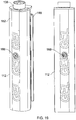
- Figure 19 shows schematically a front-perspective (left) and front (right) view of the first grip 112.
- the first grip 112 includes a fixed portion 162 and a movable portion 166.
- the fixed portion 162 is fixed relative to the door handle 100 and typically faces the user.
- the fixed portion 162 may include a graphic.
- the graphic may include a warning message to alert a user that the grip dispenses disinfectant gel or liquid.
- the movable portion 166 is moveable relative to the door handle 100 and typically faces away from the user.
- the fixed portion 162 is fixed to the end cap 136.
- the fixed portion 162 is manufactured from metal or an alloy, for example steel or aluminium.
- the movable portion 166 is manufactured from a high tensile strength thermoplastic (for example Nylon or Polyoxymethylene). However, the movable portion 166 may also be constructed from the same material as other elements of the door handle or may be constructed from a metal or alloy.
- the first grip 112 includes a grub screw 188.
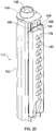
- Figure 20 shows schematically a rear-perspective view of the first grip 112. Corresponding reference numerals are used in Figure 20 as in Figure 19 .
- the rear movable portion 166 is provided with a number of dispensing elements 178 arranged in a regular pattern. Other patterns of holes are envisaged.
- the dispensing elements 178 are closed with steel balls or spheres 180 which are urged into a closed position. Balls of other materials may be used including plastics or other metals.
- the diameter of the spheres 180 is greater than the diameter of the opening of the dispensing elements 178 such that the spheres 180 are not urged out of the dispensing element 178.
- the fixed portion 162 is provided with elongate extrusions 196 which engage with elongate grooves 198 in the movable portion 166 to allow the movable portion 166 to move in the direction of arrow 199 relative to the fixed portion 162.
- the moveable portion 166 is arranged to form a trigger for dispensing liquid.
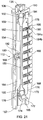
- Figure 21 shows schematically a cross section of the first grip 112 shown in Figures 19 and 20 .
- Corresponding reference numerals are used in Figure 21 as in Figures 19 and 20 .
- the end cap 136 includes an aperture 150 which allows liquid to flow into a collar 152.
- the aperture 150 is closable with the non-return valve 135.
- Attached to the collar 152 is a flexible elongate tube or tubular resilient vessel 154.
- the tubular resilient vessel 154 forms a displacement device.
- the elongate tube 154 includes a liquid inlet 158 coupled to the collar 152 using an interference fit via a lip arranged at the outer periphery of the collar 152, a central region 156 and an outlet 160.
- the outlet 160 is coupled to a coupling 174 using an interference fit via a lip arranged at the outer periphery of a collar outlet 176.
- the elongate tube 156 is manufactured from an elastomer (e.g. silicone).
- the coupling 174 is coupled to the movable portion 166 via a fluid inlet 172.
- the moveable portion 166 includes two elements 168, 170.
- the first element 168 is provided with a plurality of dispensing holes or liquid outlets 184a that run from the external surface to the opposing surface of the first element 168.
- the diameter of the liquid outlets 184a is 5 mm, but may be varied, for example the liquid outlets 184a may have a diameter in the range from 1 to 10 mm, including 1 mm, 2 mm, 3 mm, 4 mm, 5 mm, 6 mm, 7 mm, 8 mm, 9 mm or 10 mm.
- the liquid outlets 184a are sized to accommodate the balls 180.
- each of the liquid outlets 184a is provided with a seat 186.
- the seat 186 is in the form of a lip having a diameter of 4.5 mm, compared to the diameter of 5 mm of the liquid outlet 184a. It will be appreciated that the diameter of the liquid outlet 184a will be greater than the diameter of balls 180 to allow the balls to move and that the seat 186 will have an internal diameter less than the diameter of the balls 180 to prevent the balls 180 being urged from the trigger 166.
- the element 168 includes a recess in the surface opposite the external face to provide a liquid channel 176 and to accept a second element 170.
- the second element 170 includes a plurality of blind holes 184b, which align with the liquid outlets 184a of the first element 168 when the movable portion 166 is assembled.
- a spring 182 is arranged in each of the blind holes 184b and the balls 180 are arranged in each of the liquid outlets 184a, such that when the moveable portion 166 is assembled the springs 182 urge the balls 180 against the seat 186, thus providing the dispensing elements or valve mechanisms 178.
- the second element 170 is provided with a lip around its periphery edge which abuts with the first element 168.
- the liquid inlet 172 is coupled to the liquid coupling 174.
- pressure is applied to one or more of the balls 180, liquid may flow from one or more the dispensing elements 178.
- the balls 180 are urged against the seat 186, egress of liquid from the outlet 184a is prevented.
- the first and second elements 168, 170 are held together using bolts and cooperating threads in either the first or second elements 168, 170.
- the spring 182 is a helical spring, but other types of spring or resilient members may be used urge the balls to close the dispensing elements 178.
- the movable portion is held in a static position using a tang 194, 195 arranged at opposing ends of the moveable portion.
- a tang 194 is received in a recess in the cap element 136.
- a tang 196 is arranged at the opposite end of the movable element to tang 194 that is received by a guide in the lower member 116.
- the tangs 194, 196 allow the movable portion 166 to move in a direction toward the fixed portion 162, but prevent the movable portion 166 from separating completely from the fixed portion 162
- FIG 21 there is a fixed pressure plate 164 that is arranged between the elongate tube 154 and the fixed portion 162.
- the elongate tube 154 being arranged between the fixed pressure plate 164 and the movable portion 166.
- the fixed pressure plate 164 is movable by rotation of the grub screw 188.
- the grub screw 188 includes a lip which abuts with a hole 190 in the fixed portion 162.
- the fixed pressure plate 164 is provided with a cooperating thread 192. When the grub screw is rotated (in a clockwise direction, for example), the grub screw cannot move axially relative to the fixed portion 162.
- the fixed pressure plate 164 is moved away from the fixed portion 162 thus compressing the elongate tube 154, particularly in the central region 156. If the grub screw is rotated in a counter-clockwise direction, the pressure plate 164 is moved toward the fixed portion 162. It will be appreciated that the fixed pressure plate 164 may not be movable with respect to the fixed portion 162 and may be integrally formed with the fixed portion 162.
- the refill bottle 122 is placed in the door handle 100 which fills the lower reservoir 124 with liquid.
- the liquid flows into the end cap 136 from the liquid reservoir 124 and flows through the elongate member 154 and into the movable element or trigger 166. Since, the end cap 136 is substantially at the same level as the tang 194 (which is at the same height at the upper most dispensing elements 178), the liquid will continue to flow into the recess or channel 176, filling the recess. The liquid that fills the channel 176 will also flow to the dispensing elements 178. Thus the first grip is primed with liquid.
- the central region 156 of the elongate member 154 is compressed against the fixed portion 162 (and the pressure plate 164).
- liquid in the elongate member 154 flows toward the inlet 158 and the outlet 160.
- the liquid that flows toward the outlet 160 flows into the channel 170 of the movable portion 166.
- the liquid that flows toward the inlet 158 (toward the refill reservoir 124) will be prevented from flowing into the reservoir 124 by the non-return valve 135.
- the movable portion 166 is typically moved using a hand, such that digits will contact one or more of the balls 180.
- the contacted ball 180 moves away from its respective seat 186 (in the direction indicated on the figure) into the liquid outlet 184a and allows liquid to flow out of the outlet 184a under the action of the trigger 168 being moved toward the fixed portion of the grip 112.
- the elongate member 154 will return to its original (uncompressed) form such that it will be refilled from the lower reservoir 124.
- Figure 22 illustrates schematically the elements of the first grip 112 that are shown in Figure 21 in an exploded view. Corresponding reference numerals are used in Figure 22 as in Figure 21 .
- the cross section of the fixed portion 162 can be seen as being generally U-shaped.
- a generally U-shaped cross section is used to accommodate the other elements of the first grip 112.
- a periphery edge 171 of the second element 170 that abuts with a face 169 of the first element 168 is visible in Figure 22 .
- the recess 176a formed in the first element 168 is shown in Figure 22 that forms the recess or channel 176 in the trigger 166.
- Figure 23 illustrates the door handle 100, with the lid 106 removed. Corresponding reference numerals are used in Figure 23 as those used in Figures 17 and 18 .
- the lid 106 is shown removed to reveal the top of the refill bottle 122.
- the lid is shown with movable tang 109 that engages with a recess 111 in the cover 102.
- the tang 109 is movable to allow the lid 102 to be removed and/or locked into position.
- the tang 109 is operated by turned the locking mechanism 108 using an appropriate key, for example.
- the movable tang 109 may be spring loaded such that lid 106 may be pushed into position without the use of a key.
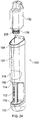
- Figure 24 illustrates schematically the door handle 100, with the lid 106 removed and the refill bottle 122 removed. Corresponding reference numerals are used in Figure 24 as those used in Figures 17 and 18 .
- the removal bottle 122 is shown in Figure 24 is removed from the door handle 100 with the lid 200 arranged at the outlet 126.
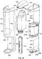
- Figure 25 illustrates schematically the door handle 100 in an exploded view (excluding the base 110). Reference numerals are used in Figure 25 corresponding to those used in Figures 17 to 24 .
- the cover 102 for the door handle 100 is shown in the figure.
- the cover 102 is shown having a generally u-shaped upper portion 102a to accommodate elements of the door handle 100.
- a lower portion of the cover 102b includes a cutaway or recessed area 207 to allow a user to grip the grip 112.
- In the lower portion of the cover 102b there is an opening 206 for the lower member 116.
- the upper portion of the cover 102a includes a region 105 that is located within the guard 104.
- the region 105 includes a recessed region so that the guard 104 is flush with the surface of the cover 102.
- this arrangement is provided for atheistic reasons.
- the back plates 202, 203 are provided with fixing holes 210 to allow the door handle to be mounted on the surface of a door.
- the lower member 116 is illustrated in the figure with an extrusion 204.
- the tang 196 (shown in Figure 21 ) of the first grip 112 engages with the extrusion 204 to allow the movable portion or trigger 166 (shown in Figure 21 ) to move in a direction toward the fixed portion 168 (shown in Figure 21 ), but prevent the movable portion 166 from separating completely from the fixed portion 168 of the first grip 112.
- Figure 26 illustrates a door handle 100 according to the second embodiment of the invention mounted on a door 212.
- Figure 27 illustrates two door handles 100 according to the second embodiment of the invention mounted on each leaf of a double door 214.
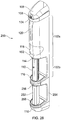
- Figure 28 illustrates schematically a door handle 250 according to a third embodiment of the present invention.
- the elements of the door handle 250 that are shared with the door handle 100 have corresponding reference numerals. Unless otherwise stated the elements of door handle 250 are the same as those of door handle 100.
- the door handle 250 includes a handle portion or second grip 252.
- the second grip 250 is arranged in a similar manner to the first grip 112 using an upper support member 256 and a lower member 258.
- the upper support member 256 includes an aperture for receiving the proximal end of the second grip 252.
- the distal end of the second grip 252 is located at the lower member 258.
- the general shape of the second grip 252 is the same as the first grip 112, such that the upper support members 114, 256 have a similar design and the lower members 116, 258 have a similar design.
- the door handle 200 includes a cover 254 which has a broadly similar form to the lower portion of the cover 102b.
- the second grip 252, the lower and upper members 256, 258 and the cover 254 are arranged between the lower member 116 and the base 110 such that the base 110 is attached to the a back plate (not shown) of the second grip 252.
- Figure 29 illustrates schematically a cross section through the door handle 250.
- FIG 29 there is provided a c-shaped back plate 266.
- the back plate is manufactured from a similar material as the back plates 202 and 203.
- the lower member 258 is attached to a lower horizontal portion of the back plate 266c.
- the upper support member 256 is attached to an upper horizontal portion of the back plate 266a.
- the cover 254 is mounted on a vertical portion of the back plate 266b.
- the cover 254 includes a cutaway region 260 to allow a user access to the second grip 252.
- the cover 254 and the back plate 266 are mountable on the surface of a door using a fixing means (e.g., a screw) that is threaded through holes in the cover 254 and the back plate 266.
- the back plates 202, 203, 266 may be formed from a single piece of material.
- the base 110 is attached to the lower horizontal portion of the back plate 266c using the attachment means 138.
- the lower support member 258 includes an extrusion 246 (similar to extrusion 204) which is received by an aperture in the second grip 252.
- the second grip 252 is attached to the back plate 266 at the lower and upper horizontal portions 266a, 266b using a fixing means, for example a self taping screw.
- the second grip 252 has a general cylindrical form with open ends. Excess liquid that is caught in the lower member 116 that flows into the opening 139 continues to flow through the second grip 252 such that it flows through an opening 262 in the lower member 258 and into the base 110. Therefore, as in the embodiment shown in Figure 17 , the base 110 can be removed for removal of excess liquid.
- the second grip 252 is manufactured from aluminium and is coated with an antibacterial coating.
- the antibacterial coating may be a titanium dioxide based nano-technology photocatalyst which destroys bacteria, spores, viruses, mould, odours and pollutants.
- the coating may be Toachclean TM or Bioclock TM.
- the grip provides a physical antibacterial action in that the organic compounds on the surface of the grip are minimised. This is in contrast to the first grip 112 that provides a chemical antibacterial action by way of dispensing a liquid or gel.
- the second grip 252 may be manufactured from a composite including a high tensile plastics and an antibacterial material (e.g. microban TM) to inhibit the growth of bacteria and mould.
- the second grip 252 may be manufactured from copper.
- the door handle may be provided with an ultra violet (UV) light source that illuminates a surface of the second grip 252 to sterilize the surface of the second grip 252.
- UV ultra violet
- a commercially available low-pressure mercury-vapour lamp that emits light at 254 nm may be used. Therefore, the second grip does not require an antibacterial coating and can be manufactured from aluminium, for example.
- the second grip is shown in arranged below the first grip. However, other configurations are envisaged such as side by side or the first grip below the second grip.
- the first and second grips are shown vertically arranged, but may also be horizontally arranged on the door.
- Figure 30 illustrates the door handle 250 according to the third embodiment of the invention mounted on a door 212.
- Figure 31 illustrates two door handles 250 according to the third embodiment of the invention mounted on each leaf of a double door 214.
- FIG 32 illustrates schematically a cross section through a door handle 100 according to a fourth embodiment.
- the door handle is the same as that of the second embodiment except for the following differences.
- the opening 132 is provided with a flap 266 that is pivotably mounted adjacent the opening 132 on the collar 128.
- the flap 266 includes a coiled or helical spring 268 that urges the flap 266 closed when there is nothing acting against it. When the flap 266 is the closed position, it closes the opening 132 to prevent contaminates and debris entering the reservoir 124.
- An upper portion of the reservoir 124 includes a vent (not shown) that allows air to exit the reservoir 124 as liquid enters via the opening 126. The vent is also closed by the flap 266 when it is in the closed position.
- the flap 266 is moved from the closed position to an open position by a filament 264 that extends from an end cap 270 fitted to the opening 126 of the upper reservoir or refill bottle 122.
- the end cap 270 includes an opening 262 to allow liquid to exit and to allow the piercing element 130 to pierce the seal 127.
- Figure 33 illustrates the refill bottle or upper reservoir 122 according to the fourth embodiment of the invention.
- the refill bottle 122 is provided with an end cap 270 which includes the filament 264 and the opening 262 to expose the seal (not show).
- the reservoir may be supplied with a regular end cap (for example one without the opening or the filament) and the end cap is replaced for the one shown in the figure before installing it in the handle.
- flap arrangement shown in Figure 32 may also be applied to modify the twin grip door handle of the third embodiment shown in Figure 28 .
- An antibacterial or disinfectant from the upper and lower reservoirs is dispensed from the first grip in the form of a liquid or gel.
- the closure of the liquid outlets in the trigger may be provided with leaf springs in the form of tabs bent from a single strip that urge a ball or other complimentary shaped device into the outlet.
- the liquid outlets may be closed by a hemispherical solid that is urged in the outlet.
- the closure of the liquid outlets in the trigger may be provided with individual closure members including integrally moulded resilient fingers, which urge their closure members into the liquid outlets. It will be appreciated that the grip may not be provided with closure members.
- the flexible elongate tube may be replaced with multiple pumps each in liquid communication with the reservoir.
- the pump may be a compressible vessel that is disposed between the fixed and movable (trigger) portion of the first grip.
- Each of the individual pumps may be provide with a liquid outlet that is coupled an outlet in the grip.
- the movable portion compresses each of the pumps against the fixed portion such that liquid is dispensing from the pump's respective outlet onto a surface of the grip.
- the liquid may be dispensed from the first grip using a piston and cylinder device mounted with the first grip.
- liquid may be dispensed from the first grip using a diaphragm and chamber device mounted within the first grip.
- the first grip may be provided with a return spring to return the trigger after it has been gripped.
Landscapes
- Health & Medical Sciences (AREA)
- Public Health (AREA)
- Epidemiology (AREA)
- Veterinary Medicine (AREA)
- Life Sciences & Earth Sciences (AREA)
- Animal Behavior & Ethology (AREA)
- General Health & Medical Sciences (AREA)
- Chemical & Material Sciences (AREA)
- Chemical Kinetics & Catalysis (AREA)
- General Chemical & Material Sciences (AREA)
- Mechanical Engineering (AREA)
- Engineering & Computer Science (AREA)
- Dispersion Chemistry (AREA)
- Lock And Its Accessories (AREA)
- Apparatus For Disinfection Or Sterilisation (AREA)
- Closures For Containers (AREA)
Description
- The present invention relates to a door handle adapted to apply liquid or gel to a user's hand. Application of disinfectant gel to users' hands is recognised to improve cleanliness and control spread of infection, particularly in public buildings such as schools and hospitals. Typically self standing or wall mounted disinfectant sprays or pumps are fitted at door ways to allow a user to apply the disinfectant before entering a building or entering a room within the building. However, despite being instructed, not all users apply the disinfectant. Therefore, an alternative approach is needed.
- A known approach is to provide a door handle that applies a disinfectant in the form of a liquid or gel to a user's hand. Known door handles for applying liquid or gel to a user's hand fall within two designs.
- In the first design, a door handle is fitted with a pump arrangement, typically in the form of a piston, see reference documents [1, 2, 3]. The pump is in fluid communication with a reservoir containing the disinfectant liquid or gel. The pump is also coupled to the door handle and the door, such that the rotary action of the door handle being turned by a user to open the door actuates the pump. When the pump is actuated the disinfectant is applied to a surface of the door handle. A similar pump device has also been applied to a pull-handle, see reference document [1]. The pull-handle is mounted to a door using mounting points that allow the handle to move with respect to the mounting points when the door handle is pulled to open the door. A pump arrangement is fitted within the door handle and coupled between the mounting points and the door handle. When the door is opened, the door handle moves with respect to its mounting points, such that the disinfectant is pumped from a reservoir coupled to the pump and onto a surface of the door handle.
- In the second design, the door handle is provided with a grip that is provided with a disinfectant gel or liquid. The disinfectant gel or liquid may be supplied from a reservoir. When a user grips the door handle the disinfectant liquid or gel is applied to the user's hand. The grip may include a porous cover, see reference documents [4, 5, 6] or the handle may be provided with an absorbent material within a hollow grip, such that he absorbent martial is exposed through holes in the hollow grip, see reference documents [5, 7]. The grip may include a plastic shroud having a fluid outlet in the form of a flap, such that when the door handle is gripped the cover is deformed to open the flap, see reference document [8]. The object of the present invention is to provide an improved disinfectant liquid or gel applying door handle.
- According to the invention there is provided a door handle adapted to apply liquid or gel (liquid/gel) to a user's hand, the handle comprising:
- a handle grip,
- a liquid/gel reservoir associated with the handle,
- a liquid/gel displacement device in the grip,
- an optional non-return valve allowing liquid/gel flow from the reservoir to the displacement device,
- a hollow trigger displaceably mounted on the grip and adapted to actuate the displacement device when the handle is gripped for displacement of liquid/gel from the displacement device, into the trigger and thence on to a hand or its digits gripping the trigger.
- Although reservoir could be arranged in use below the displacement device, with the liquid/gel being sucked up from it, normally the use position of the reservoir will be above the grip with gravity assisting or causing the liquid/gel to flow down and.
- Whilst it is envisaged that the displacement device could be a piston and cylinder device, or a diaphragm and chamber device, which devices would normally be expected to require a return spring for the cylinder or chamber and the trigger, preferably, the displacement device is a resilient device of elastomeric material adapted to return from its shape after displacement of liquid or gel to its original shape for replenishing the displacement device.
- In accordance with a particular feature, the trigger is provided with a plurality of liquid/gel outlets which are normally closed and are individually opened by digital pressure on them, whereby the liquid or gel is expelled selectively where the digits act against the trigger.
- In the prototype, individual balls are provided to close individual outlets, with each ball being urged into its outlet by a respective spring. The springs can be coil springs or leaf springs in the form of tabs bent from a single strip. For production, it is envisaged that the balls can be replaced by closure members integrally moulded to resilient fingers, which urge their closure members into the outlets.
- The door handle may comprise a second grip adapted to provide a physical antibacterial action to complement the liquid/gel of the first grip which provides a chemical antibacterial action.
- The second grip may have a surface made of a material with an antibacterial action, or the second grip may incorporate an ultraviolet (UV) light source adapted to radiate UV light from inside the second grip to a UV-transparent outer surface of the grip, thereby providing an antibacterial action.
- The first grip may extend vertically and the second grip may extend vertically and the second grip may be arranged below and in line with the first grip.
- The door handle may comprise a guard member arranged to protect the reservoir from impact, if a door on which the handle is mounted is opened and brought into contact with an adjacent wall.
- The door handle may comprise a second, upper liquid/gel reservoir removably mounted on the handle which, when fitted, is in fluid communication with the lower liquid/gel reservoir by virtue of an aperture of the upper liquid/gel reservoir engaging with an aperture of the lower liquid/gel reservoir.
- The lower liquid/gel reservoir may have a flap that is arranged to be movable between a closed position and an open position, wherein absent actuation and when the upper liquid/gel reservoir is not fitted the flap adopts the closed position in which the flap forms a closure over the aperture in the lower liquid/gel reservoir and wherein fitment of the upper liquid/gel reservoir to the handle urges the flap into its open position which allows liquid/gel transfer from the upper liquid/gel reservoir to the lower liquid/gel reservoir.
- The lower liquid/gel reservoir may comprise a vent element arranged in an upper surface portion thereof, which is connected to the flap, such that when the flap is in the closed position the vent is closed and when the flap is in the open position the vent is open to facilitate filling of the lower liquid/gel reservoir with liquid/gel from the upper liquid/gel reservoir.
- The lower liquid/gel reservoir may have an integral visual level indicator or may comprise a light arranged to illuminate at least one of the upper and lower liquid/gel reservoirs and a switch arranged to be actuated by fitment of the upper liquid/gel reservoir and thereby turn on the light.
- According to an embodiment of the invention there is provided a door to which is fitted a door handle according to the invention. If the door handle comprises a first and second grip, the first grip may be arranged at an optimum height for door actuation by an adult so that the second grip is lower, thereby through ergonomics making it more likely that a user will open the door using the first grip.
- The invention is now described by way of example only with reference to the following drawings in which:
-
Figure 1 is a perspective view of a door handle in accordance with a first embodiment of the invention; -
Figure 2 is a similar perspective view of the door handle ofFigure 1 , sectioned on a central vertical plane; -
Figure 3 is a perspective view of a door plate of the door handle; -
Figure 4 is a view similar toFigure 2 on a larger scale; -
Figure 5 is a view similar toFigure 4 with many components removed to show a metal pressing supporting a grip of the handle; -
Figure 6 is a similar view of the grip only; -
Figure 7 is a horizontal section through the grip; -
Figure 8 is a non-sectioned view similar toFigure 6 ; -
Figure 9 is a non-sectioned view similar toFigure 5 ; -
Figure 10 is a sectional view from the direction of the door on a plane parallel with the door; -
Figure 11 is a sectional view on the plane ofFigure 2 in perspective from the door; -
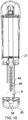
Figure 12 is a perspective view of a reservoir to displacement vessel adapter; -
Figure 13 is a perspective view of an upper moulding for locating the trigger; -
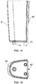
Figure 14 is a side view of a reservoir of the handle; -
Figure 15 is a plan view of the reservoir; -
Figure 16 is a sectional perspective view showing the top of the reservoir; -
Figure 17 illustrates schematically a door handle according to a second embodiment of the invention; -
Figure 18 illustrates schematically a cross section of the door handle shown inFigure 17 ; -
Figure 19 shows schematically a front-perspective (left) and front (right) view of a first grip; -
Figure 20 shows schematically a rear-perspective view of the first grip; -
Figure 21 shows schematically a cross section view of the first grip; -
Figure 22 illustrates schematically the elements of the first grip that are shown inFigure 21 in an exploded view; -
Figure 23 illustrates the door handle with a lid removed; -
Figure 24 illustrates schematically the door handle with the lid removed and a refill bottle removed; -
Figure 25 illustrates schematically the door handle shown inFigure 17 in an exploded view; -
Figure 26 illustrates the door handle according to the second embodiment of the invention mounted on a door; -
Figure 27 illustrates a pair of door handles according to the second embodiment of the invention mounted on a pair of doors; -
Figure 28 illustrates schematically a door handle according to a third embodiment of the present invention; -
Figure 29 illustrates schematically a cross section of the door handle shown inFigure 28 ; -
Figure 30 illustrates the door handle according to the third embodiment of the invention mounted on a door; and -
Figure 31 illustrates a pair of door handles according to the third embodiment of the invention mounted on a pair of doors; -
Figure 32 illustrates schematically a cross section through thedoor handle 100 shown inFigure 18 according to a fourth embodiment of the invention; and -
Figure 33 illustrates the refill bottle for the fourth embodiment of the invention. -
Figures 1 to 16 illustrate a door handle according to a first embodiment of the invention. - Referring first to
Figure 1 of the drawings, a door handle 1 has agrip 2 connected via twobrackets 3, 4 to adoor plate 5 fast in use with a door (not shown). Above the grip is arranged adisinfectant gel reservoir 6. Thedoor plate 5 extends up to afurther bracket 7. Atrigger 8 on the door side of the grip is displaceable towards the grip to dispense disinfectant gel from reservoir onto digits of a hand pulling on the grip. - The description of
Figures 1 to 16 will describe in sequence: - the structural arrangement of the grip;
- the gel displacement arrangements; and then
- the ancillary details.
- There are numerous Figures (
Figures 1 to 16 ) in the drawings, which are CAD drawings, with views chosen to illustrate particular features. It is suggested that if a feature cannot be found quickly in one Figure, the others should be referred to. - The
grip 2 is based on anextrusion 11, having twobores 12 in itssidewalls 14. It is fixed to the door via a sheet metal pressing 15, having acentral web 16 against the door in use and upper andlower flanges plastics material mouldings brackets 3,4, although they are in reality covers.Screws 21 passing through the flanges engage in thebores 12 for fastening theextrusion 11 to the pressing. - The
door plate 5 is a single moulding extending the height of the handle and havingapertures 22 aligned with apertures in the web of the pressing for screws (not shown) to fix the handle to the door. The screws fasten the pressing 15, by acting via the door plate. - The
extrusion 11 has afront wall 31, albeit covered with adecorative strip 32. Within the front wall, and adjustably positioned by agrub screw 33, is astatic pressure plate 34 for a tubularresilient vessel 35. On the other side of the vessel, there is arranged a movingpressure plate 36, against which thetrigger 8 bears. The trigger haslips 37 which pass around the outside oflips 38 of theextrusion 11, thus locating the trigger laterally whilst allowing it to be moved towards the extrusion. Internally of the extrusion, the trigger bears atlongitudinal strips 39 againststeps 40 on the moving pressure plate. These two parts are adhered and sealed together at the strips/steps, with the strips being interconnected top and bottom byfillets 41 between thestrips 39 fitting and sealed to complementary formations on the moving pressure plate. Arrangements for locating the trigger at its ends will be described below. - Internally and along their length, the trigger and the moving pressure plate define a void 42. In its
face 43 facing thedoor plate 5, the trigger plate has an array ofapertures 44, each normally closed by aball 45, the balls being held intoseats 46 internally of the apertures bysprings 47 bearing against the bottoms ofblind sockets 48 in the pressure plate. - Towards the bottom of the pressure plate, it is provided with a
hollow boss 51 which communicates with the void 42. It carries abend 52, which is engaged in the lower end of thetubular vessel 35. Bearing in mind that the upper end of the vessel has anon-return valve 53 to be described in more detail below, it will be appreciated that: - when the vessel is full of disinfectant gel which has flowed on through the
bend 52 and up into the void 42 and - when the trigger is pulled towards the
extrusion 11 of thegrip 2, the moving pressure plate squeezes the vessel against thestatic pressure plate 34, displacing gel. This flows into the void 42 and out at ones of the balls that were urged in against their springs by manual pulling on the handle. Thus disinfecting gel is displaced onto the hand. - The lower end of the trigger and moving
pressure plate assembly 36/8 hastangs 54 which engage in a secondarylower moulding 55 on the top side of thelower flange 18, whereas themoulding 20 covers the underside of the flange. These two mouldings are held to the flange by ascrew 56. Themoulding 55 has arecess 57 in which the tangs engage, restricting theassembly 36/8 from moving freely backwards out of engagement with theextrusion 11. Below thebend 52, themoulding 55 has adrain 58 for allowing any excess gel to run down into thebottom moulding 20, which is dish-shaped to collect it. Periodically, on filling of the reservoir, the screw and the bottom moulding can be removed for cleaning out of any such collected gel. - The
upper cover moulding 19 is fitted below theupper flange 17 and restricts the upper end of theassembly 36/8 in similar manner, by engagement oftangs 59 in arecess 60. The top end of thedecorative strip 32 engages alower rim 61 of the cover moulding, with the rim passing on round theextrusion 11 to contain the tangs. Behind therecess 59, the moulding has twobosses 62 into which screws (not shown) pass down through theupper flange 17 to secure the moulding. Also twocruciform spigots 63 of the moulding engage inapertures 64 in the upper flange. - The upper end of the
extrusion 11 has anadapter moulding 65 engaged in it. It is captivated by theupper screws 21 passing through it via alip 66 that engages underneath theflange 17. On its underside, the adapter carries ahollow boss 67 onto which the top end of theresilient vessel 35 fits. On its top side and passing through theflange 17, the adapter has anotherhollow boss 68, with acentral spigot 69. - The reservoir has a smaller depending
open boss 71, with two further closedbosses 72, which engage thecruciform spigots 63 extending through theflange 17. With an interference fit, the open boss receives aninsert 74, with an out-turnedlip 75. This captivates an O-ring 76. The latter seals theboss 71 in theboss 68. The insert also loosely captivates anon-return valve ball 77, at atapered seat 78. When the reservoir is not fitted to the handle, the ball engages theseat 78 and closes theboss 71 against out flow of gel. When the reservoir is fitted, thespigot 69 lifts the ball off theseat 78. Theboss 71 has a complementary,oppositely facing seat 79, against which the ball is lifted to act in a non-return valve manner against return flow on gripping of the handle and movement of the trigger into theextrusion 11. Thus the gel in thevessel 35 is displaced out at the trigger. When the trigger is released, the vessel recovers its shape. Theballs 45 seal the trigger against ingress of air under action of their springs and the vessel is refilled. - It will be appreciated that the balls are arranged against their seats in a manner such as to prevent egress of gel except when they are pressed in. They are not arranged as non-return valves complementary the
non-return valve 53 such that, if the trigger were pressed in without pressure on any of the balls, gel would flow at all the balls. - A
top moulding 81, which appears to be a bracket in the same way that mouldings 19, 20 appear to bebrackets 3,4, is provided to captivate the reservoir in its use position. It has arotary latch 82. This and the top end of the door plate havecomplementary formations filler port 85 and a bung 86 for topping up of the reservoir with gel without its removal from the handle. - A final detail is that the reservoir has
rear rib 87, which engages in aslot 88 in the door plate for lateral location of the reservoir. -
Figure 17 illustrates schematically adoor handle 100 according to a second embodiment of the invention. Unless otherwise stated the elements of the door handle are manufactured from thermoplastics (for example Polyethylene or Polypropylene). - The
door handle 100 includes acover 102 that covers elements of thedoor handle 100. The cover includes anupper portion 102a andlower portion 102b. Theupper portion 102a includes atransparent window 118 to allow a level of liquid in an internal reservoir (not shown) to be viewed. Theupper portion 102a includes a furthertransparent window 120 to allow a level of liquid contained in a refill bottle (not shown) to be viewed. Theupper portion 102a covers the internal reservoir and the refill bottle. It will be appreciated that thecover 102 may be manufactured from a transparent material, such that individual viewing windows are not required. Thecover 102 is generally shaped to provide a cover for the front and sides of thedoor handle 100. Thedoor handle 100 includes a back plate (not shown) to allow the door handle to be mounted to a door. Thecover 102 is removably mounted on the back plate. Thelower portion 102b is shaped to allow a user's hand to access a handle portion orfirst grip 112. - The
door handle 100 includes aremovable lid 106 mounted on thecover 102 and is manufactured from similar material to thecover 102. Thelid 106 includes alocking mechanism 108 that accepts a key. When an appropriate key is inserted and turned in thelocking mechanism 108 thelid 106 may be removed. The locking mechanism is of the type typically used for sanitary products such as paper towel dispensers. - The
door handle 100 includes a removable bottom cover orbase 110. Thebase 110 is attached to the door handle using an appropriate locking mechanism or suitable attaching means (e.g. a self tapping screw-not shown). The base 110 may be secured using a locking mechanism that allows it to be easily removed. The locking mechanism may be operated using the same key as thelid 106. Thebase 110 is attached to a portion of the back plate (not shown). Thebase 110 is removable to allow for construction of the door handle and to allow for further grips to be added to the door handle. Furthermore, thebase 110 collects excess liquid from thefirst grip 112. Therefore, thebase 110 is removable to allow for the excess liquid to be removed. A dish-shapedlower member 116 is mounted below thefirst grip 112 and is shaped to collect excess liquid from thefirst grip 112, which drains into thebase 110. - The
first grip 112 is secured to thedoor handle 100 by a portion of the back plate (not shown) at thelower member 116 and anupper support member 114. Thelower member 116 includes an extrusion (not shown), to locate the a proximal end of thefirst grip 112. Thefirst grip 112 is typically secured to the back plate using self taper screws, for example. The distal end of thefirst grip 112 extends into a recess shaped to accept the distal end of thefirst grip 112 of theupper support member 114. - The
door handle 100 includes a guard orbumper 104. In this example theguard member 104 is integral to the back plate (not shown) and surrounds a portion of theupper portion 102a of thecover 102. The guard member is arranged to protect the door handle from impact, for example, if a door to which the handle is fitted is opened and brought into contact with an adjacent wall. Theguard 104 is constructed from aluminium, but may also be manufactured from high tensile strength plastics (for example Nylon or Polyoxymethylene). Theguard 104 may also be constructed from the same material as other elements of the door handle or may be constructed from a different metal or alloy, for example, steel. Theguard 104 may be coated with rubber or coloured plastic. Theguard 104 is typically arranged such that when thedoor handle 100 is mounted on a door, theguard 104 extends further from the door than the other elements of thedoor handle 100. Therefore, if the door is opened such that it makes contact with an adjacent wall, theguard 104 prevents damage to thedoor handle 100. -
Figure 18 illustrates schematically a cross section through the centre of thedoor handle 100 shown inFigure 17 . Corresponding reference numerals are used inFigure 17 . - Located inside the
door handle 100 is a refill bottle orupper reservoir 122. Therefill bottle 122 is located in an upper part of thedoor handle 100 and is arranged in an inverted manner such that anopening 126 in therefill bottle 122 is arranged at the bottom or lower part of the refill bottle. Therefill bottle 122 is located in thedoor handle 100 such that the contents of therefill bottle 122 can be viewed through theviewing window 120. It will be appreciated that therefill bottle 122 may also include an opening at the opposite end of theopening 126 to allow for therefill bottle 122 to be refilled. Theopening 126 of therefill bottle 122 includes aseal 127 that is broken when therefill bottle 122 is located in thedoor handle 100. The neck of theopening 126 also includes a thread such that a removable cap may be fitted when the refill bottle is not located in thedoor handle 100. In this example, therefill bottle 122 is fitted with an end cap orlid 200 that includes an aperture oroutlet 201, such that the refill bottle is placed in the door handle with thelid 200 in place. However, it will be appreciated that thelid 200 having the outlet may be fitted to therefill bottle 122 before it is placed in thedoor handle 100. When therefill bottle 200 is not in thedoor handle 100, it may be fitted with a lid having no liquid outlet. - In the
door handle 100, a liquid reservoir orlower reservoir 124 is located below therefill bottle 122. Theliquid reservoir 124 is located in thedoor handle 100, such that the contents of the reservoir 124 (e.g. antibacterial or disinfectant liquid or gel) can be viewed through theviewing window 118. The upper part of theliquid reservoir 124 includes acollar 128 to receive theopening 201 of thelid 200 of therefill bottle 122. Thecollar 128 includes anupstanding piercing element 130, such that when thelid 200 of therefill bottle 122 is located in thecollar 128, the piercingelement 130 pierces theseal 127 of therefill bottle 122. The piercingelement 130 feeds through the opening 131 if thelid 200. Thecollar 128 also includes anopening 132 to allow liquid from therefill bottle 122 to flow from theopening 126 of therefill bottle 122 into thereservoir 124 under the action of gravity. - In this example above and below are used in reference to the normal orientation of the door handle when it is attached to a door. In the normal orientation of the door handle, the grip is at the lowest part of the door handle. It will be appreciated that the refill bottle may not be mounted above the lower reservoir, rather alongside or below it. If the refill bottle is not mounted above the lower reservoir, pressure may be used to move the liquid from the refill bottle to the lower reservoir. For example, a source of compressed gas may be used.
- The lower part of the
reservoir 124 includes an opening oraperture 134 to allow liquid to flow from thereservoir 124 into thefirst grip 112. Theopening 134 of thereservoir 124 is in fluid communication with anend cap 136 of thefirst grip 112. - The
opening 134 includes a one-way ornon-return valve 135 that allows liquid to flow from thereservoir 124 into thefirst grip 112, but prevents liquid flow from thefirst grip 112 to thereservoir 124. However, it will be appreciated that a one-valve is not necessary for operation of the door handle. For example, thelower reservoir 124 and/or theupper reservoir 122 may be pressured using a source of pressurised gas or may include a spring mounted piston. Alternatively, the weight of the liquid in thelower reservoir 124 may be sufficient to prevent liquid flow from thefirst grip 112 to thereservoir 124. - Adjacent the
collar 128 of theliquid reservoir 124, there is located anelectrical switch 140, e.g. a micro switch. Theswitch 140 is connected to a power source (not shown), for example, a button battery. Theswitch 140 and battery are electrically connected to a light emitting diode (LED) 146 such that when theswitch 140 is in an "on" position the LED illuminates thelower reservoir 124. Other light sources may be used and may be provided in a different location to illuminate part or all of the lower and/or upper reservoir.. Theswitch 140 is arranged such that when arefill bottle 122 is located in thedoor handle 100, therefill bottle 122 applies pressure to theswitch 140 and changes the switch to the "on" position. When therefill bottle 122 is removed the switched is changed to an "off" position. - Inside the
reservoir 124 there is provided alevel indicator ball 148. Theball 148 is designed to be buoyant in the liquid contained in thereservoir 124, such that when the liquid level in thereservoir 124 rises and falls, theball 148 will typically rise and fall with the level of liquid. The inside of thereservoir 124 is provided with aguide 146 that prevents theball 148 from moving away from theviewing window 118. Theindicator ball 148 allows a user to efficiently check the level of the liquid in the reservoir. This could also be achieved by viewing the level of liquid. Furthermore, thelower reservoir 124 acts as a reserve reservoir, such that when therefill bottle 122 is empty liquid can still be provided by thelower reservoir 124 until the refill bottle is replace or refilled. - In the cross section shown in
Figure 18 , an attachment means 138 for the base 110 can be viewed. The attachment means 138 is in the form of a fixing that is inserted through a hole in aback plate 202 and positively engages with the lower member116 of thedoor handle 100. Anopening 139 is provided in thelower member 116 that allows for liquid from thefirst grip 112 to drain from thelower member 116 and into thebase 110. - An
opening 142 can be view in the cross section shown inFigure 18 which allows a user to grip and apply pressure to the doorfirst grip 112. - In
Figure 18 , the back plate of thedoor handle 100 can be viewed. The back plate includes two separable portions, anupper back plate 203 and alower back plate 202. It will be appreciated that these may be formed from a single sheet of material. The back plate is manufactured from an alloy or metal, such a aluminium or steel, but may also be manufactured from a high tensile plastics. - The
upper back plate 203 is L-shaped, such that avertical portion 203a is attachable to a door and ahorizontal portion 203b provides a support and fixing means for therefill bottle 124, theupper support member 114 and thefirst grip 112. Theguard 104 is also mounted to thevertical portion 203a or may be integral to it. Thelower back plate 202 is L-shaped, such that avertical portion 202a is attachable to a door and theupper back plate 203. Ahorizontal portion 202b provides a support and fixing means for thefirst grip 112, the lower dish-shapedmember 116 andbase 110. Horizontal and vertical are referred to in respect of a door on which the handle is mounted. -
Figure 19 shows schematically a front-perspective (left) and front (right) view of thefirst grip 112. Thefirst grip 112 includes a fixedportion 162 and amovable portion 166. The fixedportion 162 is fixed relative to thedoor handle 100 and typically faces the user. As shown in the figure the fixedportion 162 may include a graphic. The graphic may include a warning message to alert a user that the grip dispenses disinfectant gel or liquid. Themovable portion 166 is moveable relative to thedoor handle 100 and typically faces away from the user. The fixedportion 162 is fixed to theend cap 136. The fixedportion 162 is manufactured from metal or an alloy, for example steel or aluminium. Themovable portion 166 is manufactured from a high tensile strength thermoplastic (for example Nylon or Polyoxymethylene). However, themovable portion 166 may also be constructed from the same material as other elements of the door handle or may be constructed from a metal or alloy. Thefirst grip 112 includes agrub screw 188. -
Figure 20 shows schematically a rear-perspective view of thefirst grip 112. Corresponding reference numerals are used inFigure 20 as inFigure 19 . - The rear
movable portion 166 is provided with a number of dispensingelements 178 arranged in a regular pattern. Other patterns of holes are envisaged. The dispensingelements 178 are closed with steel balls orspheres 180 which are urged into a closed position. Balls of other materials may be used including plastics or other metals. The diameter of thespheres 180 is greater than the diameter of the opening of the dispensingelements 178 such that thespheres 180 are not urged out of the dispensingelement 178. The fixedportion 162 is provided withelongate extrusions 196 which engage withelongate grooves 198 in themovable portion 166 to allow themovable portion 166 to move in the direction ofarrow 199 relative to the fixedportion 162. Themoveable portion 166 is arranged to form a trigger for dispensing liquid. -
Figure 21 shows schematically a cross section of thefirst grip 112 shown inFigures 19 and20 . Corresponding reference numerals are used inFigure 21 as inFigures 19 and20 . - In
Figure 21 , theend cap 136 includes anaperture 150 which allows liquid to flow into acollar 152. Theaperture 150 is closable with thenon-return valve 135. Attached to thecollar 152 is a flexible elongate tube or tubularresilient vessel 154. The tubularresilient vessel 154 forms a displacement device. Theelongate tube 154 includes aliquid inlet 158 coupled to thecollar 152 using an interference fit via a lip arranged at the outer periphery of thecollar 152, acentral region 156 and anoutlet 160. Theoutlet 160 is coupled to acoupling 174 using an interference fit via a lip arranged at the outer periphery of acollar outlet 176. Theelongate tube 156 is manufactured from an elastomer (e.g. silicone). - The
coupling 174 is coupled to themovable portion 166 via afluid inlet 172. Themoveable portion 166 includes twoelements first element 168 is provided with a plurality of dispensing holes orliquid outlets 184a that run from the external surface to the opposing surface of thefirst element 168. The diameter of theliquid outlets 184a is 5 mm, but may be varied, for example theliquid outlets 184a may have a diameter in the range from 1 to 10 mm, including 1 mm, 2 mm, 3 mm, 4 mm, 5 mm, 6 mm, 7 mm, 8 mm, 9 mm or 10 mm. Theliquid outlets 184a are sized to accommodate theballs 180. The external surface of thefirst element 168 forms a trigger surface of thefirst grip 112. At the external surface of thefirst element 168, each of theliquid outlets 184a is provided with aseat 186. Theseat 186 is in the form of a lip having a diameter of 4.5 mm, compared to the diameter of 5 mm of theliquid outlet 184a. It will be appreciated that the diameter of theliquid outlet 184a will be greater than the diameter ofballs 180 to allow the balls to move and that theseat 186 will have an internal diameter less than the diameter of theballs 180 to prevent theballs 180 being urged from thetrigger 166. Theelement 168 includes a recess in the surface opposite the external face to provide aliquid channel 176 and to accept asecond element 170. Thesecond element 170 includes a plurality ofblind holes 184b, which align with theliquid outlets 184a of thefirst element 168 when themovable portion 166 is assembled. During assembly of themovable portion 166, aspring 182 is arranged in each of theblind holes 184b and theballs 180 are arranged in each of theliquid outlets 184a, such that when themoveable portion 166 is assembled thesprings 182 urge theballs 180 against theseat 186, thus providing the dispensing elements orvalve mechanisms 178. To provide achannel 176 between the first andsecond elements movable portion 166, thesecond element 170 is provided with a lip around its periphery edge which abuts with thefirst element 168. Liquid enters thechannel 176 from theliquid inlet 172 arranged in thesecond element 170. Theliquid inlet 172 is coupled to theliquid coupling 174. When pressure is applied to one or more of theballs 180, liquid may flow from one or more the dispensingelements 178. However, when theballs 180 are urged against theseat 186, egress of liquid from theoutlet 184a is prevented. - The first and
second elements second elements - In this example, the
spring 182 is a helical spring, but other types of spring or resilient members may be used urge the balls to close the dispensingelements 178. - The movable portion is held in a static position using a
tang tang 194 is received in a recess in thecap element 136. Atang 196 is arranged at the opposite end of the movable element totang 194 that is received by a guide in thelower member 116. Thetangs movable portion 166 to move in a direction toward the fixedportion 162, but prevent themovable portion 166 from separating completely from the fixedportion 162 - In
Figure 21 , there is a fixedpressure plate 164 that is arranged between theelongate tube 154 and the fixedportion 162. Theelongate tube 154 being arranged between the fixedpressure plate 164 and themovable portion 166. The fixedpressure plate 164 is movable by rotation of thegrub screw 188. Thegrub screw 188 includes a lip which abuts with ahole 190 in the fixedportion 162. The fixedpressure plate 164 is provided with a cooperatingthread 192. When the grub screw is rotated (in a clockwise direction, for example), the grub screw cannot move axially relative to the fixedportion 162. Therefore, the fixedpressure plate 164 is moved away from the fixedportion 162 thus compressing theelongate tube 154, particularly in thecentral region 156. If the grub screw is rotated in a counter-clockwise direction, thepressure plate 164 is moved toward the fixedportion 162. It will be appreciated that the fixedpressure plate 164 may not be movable with respect to the fixedportion 162 and may be integrally formed with the fixedportion 162. - In operation, the
refill bottle 122 is placed in thedoor handle 100 which fills thelower reservoir 124 with liquid. The liquid flows into theend cap 136 from theliquid reservoir 124 and flows through theelongate member 154 and into the movable element ortrigger 166. Since, theend cap 136 is substantially at the same level as the tang 194 (which is at the same height at the upper most dispensing elements 178), the liquid will continue to flow into the recess orchannel 176, filling the recess. The liquid that fills thechannel 176 will also flow to the dispensingelements 178. Thus the first grip is primed with liquid. When themovable portion 166 is moved toward the fixedportion 162, thecentral region 156 of theelongate member 154 is compressed against the fixed portion 162 (and the pressure plate 164). Thus liquid in theelongate member 154 flows toward theinlet 158 and theoutlet 160. The liquid that flows toward theoutlet 160 flows into thechannel 170 of themovable portion 166. The liquid that flows toward the inlet 158 (toward the refill reservoir 124) will be prevented from flowing into thereservoir 124 by thenon-return valve 135. Themovable portion 166 is typically moved using a hand, such that digits will contact one or more of theballs 180. The contactedball 180 moves away from its respective seat 186 (in the direction indicated on the figure) into theliquid outlet 184a and allows liquid to flow out of theoutlet 184a under the action of thetrigger 168 being moved toward the fixed portion of thegrip 112. When the first grip is released, theelongate member 154 will return to its original (uncompressed) form such that it will be refilled from thelower reservoir 124. -
Figure 22 illustrates schematically the elements of thefirst grip 112 that are shown inFigure 21 in an exploded view. Corresponding reference numerals are used inFigure 22 as inFigure 21 . - In
Figure 22 , the cross section of the fixedportion 162 can be seen as being generally U-shaped. A generally U-shaped cross section is used to accommodate the other elements of thefirst grip 112. Aperiphery edge 171 of thesecond element 170 that abuts with aface 169 of thefirst element 168 is visible inFigure 22 . Therecess 176a formed in thefirst element 168 is shown inFigure 22 that forms the recess orchannel 176 in thetrigger 166. -
Figure 23 illustrates thedoor handle 100, with thelid 106 removed. Corresponding reference numerals are used inFigure 23 as those used inFigures 17 and18 . - In
Figure 23 , thelid 106 is shown removed to reveal the top of therefill bottle 122. The lid is shown withmovable tang 109 that engages with arecess 111 in thecover 102. It will be appreciated that the lid is provided with atang 109 on opposing sides of thelid 106 and thecover 102 is provided with a recess on opposing sides of thecover 102. Thetang 109 is movable to allow thelid 102 to be removed and/or locked into position. Thetang 109 is operated by turned thelocking mechanism 108 using an appropriate key, for example. Themovable tang 109 may be spring loaded such thatlid 106 may be pushed into position without the use of a key. -
Figure 24 illustrates schematically thedoor handle 100, with thelid 106 removed and therefill bottle 122 removed. Corresponding reference numerals are used inFigure 24 as those used inFigures 17 and18 . Theremoval bottle 122 is shown inFigure 24 is removed from thedoor handle 100 with thelid 200 arranged at theoutlet 126. -
Figure 25 , illustrates schematically thedoor handle 100 in an exploded view (excluding the base 110). Reference numerals are used inFigure 25 corresponding to those used inFigures 17 to 24 . - The
cover 102 for thedoor handle 100 is shown in the figure. Thecover 102 is shown having a generally u-shapedupper portion 102a to accommodate elements of thedoor handle 100. A lower portion of thecover 102b includes a cutaway or recessedarea 207 to allow a user to grip thegrip 112. In the lower portion of thecover 102b, there is anopening 206 for thelower member 116. There is also provided in the lower portion of thecover 102a anopening 208 to receive theupper support member 114. The upper portion of thecover 102a includes aregion 105 that is located within theguard 104. In this example, theregion 105 includes a recessed region so that theguard 104 is flush with the surface of thecover 102. However, it will be appreciated that this arrangement is provided for atheistic reasons. - The
back plates holes 210 to allow the door handle to be mounted on the surface of a door. - The
lower member 116 is illustrated in the figure with anextrusion 204. The tang 196 (shown inFigure 21 ) of thefirst grip 112 engages with theextrusion 204 to allow the movable portion or trigger 166 (shown inFigure 21 ) to move in a direction toward the fixed portion 168 (shown inFigure 21 ), but prevent themovable portion 166 from separating completely from the fixedportion 168 of thefirst grip 112. -
Figure 26 illustrates adoor handle 100 according to the second embodiment of the invention mounted on adoor 212. -
Figure 27 illustrates two door handles 100 according to the second embodiment of the invention mounted on each leaf of adouble door 214. -
Figure 28 illustrates schematically adoor handle 250 according to a third embodiment of the present invention. - The elements of the
door handle 250 that are shared with thedoor handle 100 have corresponding reference numerals. Unless otherwise stated the elements ofdoor handle 250 are the same as those ofdoor handle 100. - The
door handle 250 includes a handle portion orsecond grip 252. Thesecond grip 250 is arranged in a similar manner to thefirst grip 112 using anupper support member 256 and alower member 258. Theupper support member 256 includes an aperture for receiving the proximal end of thesecond grip 252. The distal end of thesecond grip 252 is located at thelower member 258. The general shape of thesecond grip 252 is the same as thefirst grip 112, such that theupper support members lower members - The
door handle 200 includes acover 254 which has a broadly similar form to the lower portion of thecover 102b. In the figure, thesecond grip 252, the lower andupper members cover 254, are arranged between thelower member 116 and the base 110 such that thebase 110 is attached to the a back plate (not shown) of thesecond grip 252. -
Figure 29 illustrates schematically a cross section through thedoor handle 250. - In
Figure 29 there is provided a c-shapedback plate 266. The back plate is manufactured from a similar material as theback plates lower member 258 is attached to a lower horizontal portion of theback plate 266c. Theupper support member 256 is attached to an upper horizontal portion of theback plate 266a. Thecover 254 is mounted on a vertical portion of theback plate 266b. Thecover 254 includes acutaway region 260 to allow a user access to thesecond grip 252. - The
cover 254 and theback plate 266 are mountable on the surface of a door using a fixing means (e.g., a screw) that is threaded through holes in thecover 254 and theback plate 266. Theback plates - The
base 110 is attached to the lower horizontal portion of theback plate 266c using the attachment means 138. Thelower support member 258 includes an extrusion 246 (similar to extrusion 204) which is received by an aperture in thesecond grip 252. Thesecond grip 252 is attached to theback plate 266 at the lower and upperhorizontal portions - The
second grip 252 has a general cylindrical form with open ends. Excess liquid that is caught in thelower member 116 that flows into theopening 139 continues to flow through thesecond grip 252 such that it flows through anopening 262 in thelower member 258 and into thebase 110. Therefore, as in the embodiment shown inFigure 17 , the base 110 can be removed for removal of excess liquid. - The
second grip 252 is manufactured from aluminium and is coated with an antibacterial coating. The antibacterial coating may be a titanium dioxide based nano-technology photocatalyst which destroys bacteria, spores, viruses, mould, odours and pollutants. For example, the coating may be Toachclean ™ or Bioclock ™. The grip provides a physical antibacterial action in that the organic compounds on the surface of the grip are minimised. This is in contrast to thefirst grip 112 that provides a chemical antibacterial action by way of dispensing a liquid or gel. - Alternatively, the
second grip 252 may be manufactured from a composite including a high tensile plastics and an antibacterial material (e.g. microban ™) to inhibit the growth of bacteria and mould. Alternatively, thesecond grip 252 may be manufactured from copper. The door handle may be provided with an ultra violet (UV) light source that illuminates a surface of thesecond grip 252 to sterilize the surface of thesecond grip 252. For example, a commercially available low-pressure mercury-vapour lamp that emits light at 254 nm may be used. Therefore, the second grip does not require an antibacterial coating and can be manufactured from aluminium, for example. - The second grip is shown in arranged below the first grip. However, other configurations are envisaged such as side by side or the first grip below the second grip. The first and second grips are shown vertically arranged, but may also be horizontally arranged on the door.
-
Figure 30 illustrates thedoor handle 250 according to the third embodiment of the invention mounted on adoor 212. -
Figure 31 illustrates two door handles 250 according to the third embodiment of the invention mounted on each leaf of adouble door 214. -
Figure 32 illustrates schematically a cross section through adoor handle 100 according to a fourth embodiment. The door handle is the same as that of the second embodiment except for the following differences. InFigure 32 , theopening 132 is provided with aflap 266 that is pivotably mounted adjacent theopening 132 on thecollar 128. Theflap 266 includes a coiled orhelical spring 268 that urges theflap 266 closed when there is nothing acting against it. When theflap 266 is the closed position, it closes theopening 132 to prevent contaminates and debris entering thereservoir 124. An upper portion of thereservoir 124 includes a vent (not shown) that allows air to exit thereservoir 124 as liquid enters via theopening 126. The vent is also closed by theflap 266 when it is in the closed position. - The
flap 266 is moved from the closed position to an open position by afilament 264 that extends from anend cap 270 fitted to theopening 126 of the upper reservoir or refillbottle 122. Theend cap 270 includes anopening 262 to allow liquid to exit and to allow the piercingelement 130 to pierce theseal 127. When therefill bottle 122 is placed in thedoor handle 100, thefilament 264 will act against theflap 266 and move it into the open position. When therefill bottle 122 is removed theflap 266 will move to the closed poison under the action of thespring 268. -
Figure 33 illustrates the refill bottle orupper reservoir 122 according to the fourth embodiment of the invention. In the figure therefill bottle 122 is provided with anend cap 270 which includes thefilament 264 and theopening 262 to expose the seal (not show). It will appreciated that the reservoir may be supplied with a regular end cap (for example one without the opening or the filament) and the end cap is replaced for the one shown in the figure before installing it in the handle. - It will be appreciated that the flap arrangement shown in
Figure 32 may also be applied to modify the twin grip door handle of the third embodiment shown inFigure 28 . - Several variations suitable for any of the above embodiments are now discussed.
- An antibacterial or disinfectant from the upper and lower reservoirs is dispensed from the first grip in the form of a liquid or gel.
- The closure of the liquid outlets in the trigger may be provided with leaf springs in the form of tabs bent from a single strip that urge a ball or other complimentary shaped device into the outlet. For example, the liquid outlets may be closed by a hemispherical solid that is urged in the outlet. Alternatively, the closure of the liquid outlets in the trigger may be provided with individual closure members including integrally moulded resilient fingers, which urge their closure members into the liquid outlets. It will be appreciated that the grip may not be provided with closure members.
- The flexible elongate tube may be replaced with multiple pumps each in liquid communication with the reservoir. The pump may be a compressible vessel that is disposed between the fixed and movable (trigger) portion of the first grip. Each of the individual pumps may be provide with a liquid outlet that is coupled an outlet in the grip. When the handle is gripped the movable portion compresses each of the pumps against the fixed portion such that liquid is dispensing from the pump's respective outlet onto a surface of the grip.
- The liquid may be dispensed from the first grip using a piston and cylinder device mounted with the first grip. Alternatively, liquid may be dispensed from the first grip using a diaphragm and chamber device mounted within the first grip. The first grip may be provided with a return spring to return the trigger after it has been gripped.
-
- 1.
-
WO 2008/153711A1 - 2.
-
DE10014472 A1 - 3.
-
EP1164235 A3 - 4.
-
GB2421897 A - 5.
-
FR2824096 A1 - 6.
-
US2006/0245818 A1 - 7.
-
GB2436284 A - 8.
-
DE202004006845 U1
Claims (15)
- A door handle (1; 100; 250) adapted to apply liquid or gel (liquid/gel) to a user's hand, the handle (1; 100; 250) comprising:a handle grip (2; 112);a liquid/gel reservoir (6; 124) associated with the handle (1; 100; 250);characterised by:a liquid/gel displacement device (35; 154) in the grip (2; 112); anda hollow trigger (8; 166) displaceably mounted on the grip (2; 112) and adapted to actuate the displacement device (35; 154) when the handle (1; 100; 250) is gripped for displacement of liquid/gel from the displacement device (35; 154), into the trigger (8; 166) and thence on to a hand or its digits gripping the trigger (8; 166).
- The door handle (1; 100; 250) of claim 1, wherein:the reservoir (6; 124) is arranged in use below the displacement device (35; 154), with the liquid/gel being sucked up from it; orthe use position of the reservoir (6; 124) is above the grip (2; 112) with gravity assisting or causing the liquid/gel to flow down.
- The door handle (1; 100; 250) of claim 1 or 2, wherein the displacement device (35; 154) is a piston and cylinder device.
- The door handle (1; 100; 250) of claim 1 or 2, wherein the displacement device (35; 154) is a diaphragm and chamber device.
- The door handle (1; 100; 250) of claim 3 or 4, wherein the displacement device (35; 154) has a return spring for the cylinder or chamber and the trigger (8; 166).
- The door handle (1; 100; 250) of any preceding claim, wherein the displacement device (35; 154) is a resilient device of elastomeric material adapted to return from its shape after displacement of liquid or gel to its original shape for replenishing the displacement device (35; 154).
- The door handle (1; 100; 250) of any preceding claim, wherein the trigger (8; 166) is provided with a plurality of liquid/gel outlets (44; 184a) which are normally closed and are individually opened by digital pressure on them, whereby the liquid or gel is expelled selectively where the digits act against the trigger (8; 166).
- The door handle (1; 100; 250) of claim 7, wherein individual closure members (45; 180), such as balls or plugs, are provided to close individual outlets (44; 184a), with each closure member (45; 180) being urged into its outlet (44; 184a) by a respective spring (47; 182).
- The door handle (1; 100; 250) of claim 8, wherein the springs (47; 182) are coil springs or leaf springs in the form of tabs bent from a single strip.
- The door handle (1; 100; 250) of claim 7, wherein closure members (45; 180) are provided to close individual outlets (44; 184a), the closure members (45; 180) optionally being integrally moulded to resilient fingers, which urge their closure members (45; 180) into the outlets (44; 184a).
- The door handle (1; 100; 250) of any preceding claim, comprising a non-return valve (135) allowing liquid/gel flow to from the reservoir (6; 124) to the displacement device (35; 154).
- The door handle (1; 100; 250) of any preceding claim, comprising a second grip (252) adapted to provide a physical antibacterial action to complement the liquid/gel of the first grip (2; 112) which provides a chemical antibacterial action.
- The door handle (1; 100; 250) of any preceding claim, comprising a guard member (104) arranged to protect the reservoir (6; 124) from impact, if a door (212; 214) on which the handle (1; 100; 250) is mounted is opened and brought into contact with an adjacent wall.
- The door handle (1; 100; 250) of any preceding claim, comprising a second, upper liquid/gel reservoir (122) removably mounted on the handle (1; 100; 250) which, when fitted, is in fluid communication with the lower liquid/gel reservoir (124) by virtue of an aperture (262) of the upper liquid/gel reservoir (122) engaging with an aperture (132) of the lower liquid/gel reservoir (124).
- A door (212; 214) to which is fitted a door handle (1; 100; 250) according to any preceding claim.
Applications Claiming Priority (2)
| Application Number | Priority Date | Filing Date | Title |
|---|---|---|---|
| GB1006366.7A GB2484650A (en) | 2010-04-16 | 2010-04-16 | Door handle comprising a liquid/gel dispenser |
| PCT/GB2011/000590 WO2011128652A2 (en) | 2010-04-16 | 2011-04-15 | Door handle |
Publications (2)
| Publication Number | Publication Date |
|---|---|
| EP2558663A2 EP2558663A2 (en) | 2013-02-20 |
| EP2558663B1 true EP2558663B1 (en) | 2017-05-31 |
Family
ID=42245311
Family Applications (1)
| Application Number | Title | Priority Date | Filing Date |
|---|---|---|---|
| EP11716615.7A Not-in-force EP2558663B1 (en) | 2010-04-16 | 2011-04-15 | Door handle |
Country Status (7)
| Country | Link |
|---|---|
| US (1) | US9376833B2 (en) |
| EP (1) | EP2558663B1 (en) |
| JP (1) | JP5800891B2 (en) |
| AU (1) | AU2011239739B2 (en) |
| CA (1) | CA2796476C (en) |
| GB (2) | GB2484650A (en) |
| WO (1) | WO2011128652A2 (en) |
Families Citing this family (21)
| Publication number | Priority date | Publication date | Assignee | Title |
|---|---|---|---|---|
| GB2495471A (en) * | 2011-09-26 | 2013-04-17 | Michael John Lynn | A door handle dispenser mechanism for delivering an antiseptic solution onto the handle's surface |
| US9123257B2 (en) * | 2012-01-18 | 2015-09-01 | Julio Vicente | Device for facilitating detection of hygienic hand washing |
| WO2014035610A1 (en) | 2012-08-28 | 2014-03-06 | Altitude Medical Inc. | Method and apparatus for dispensing sanitizer fluid via door handles, and recording data pertaining to hand sanitization |
| US20140137369A1 (en) * | 2012-11-15 | 2014-05-22 | Brylin Innovations, LLC | Self-sanitizing door handle |
| US11039519B2 (en) * | 2013-12-18 | 2021-06-15 | Mathew Inskeep | Door mounted sanitizer light |
| US9015905B1 (en) * | 2014-02-20 | 2015-04-28 | MiniMax, Inc. | Magnetically suspended hygienic handle assembly |
| GB2530514A (en) * | 2014-09-24 | 2016-03-30 | Sanigrip Ltd | Handle assembly with liquid dispensing system |
| US9719274B2 (en) | 2015-02-09 | 2017-08-01 | Seton Healthcare Family | Door handles including hand sanitizer delivery systems, and related methods |
| US20170158417A1 (en) * | 2015-12-06 | 2017-06-08 | Ralph M. Castillo | Aerosol delivery system |
| KR101735241B1 (en) * | 2016-05-03 | 2017-05-12 | 조봉제 | Door handle for sterilizing hand |
| WO2017193088A1 (en) | 2016-05-06 | 2017-11-09 | Altitude Medical, Inc. | Method and apparatus for dispensing sanitizer fluid, opening doors and recording data pertaining to hand sanitization |
| KR102040541B1 (en) * | 2017-08-14 | 2019-11-06 | 조봉제 | Door handle for sterilizing hand |
| US10925987B2 (en) | 2018-04-27 | 2021-02-23 | KleanTouch LLC | Electronic sanitizing door handle |
| US11045568B2 (en) * | 2018-11-21 | 2021-06-29 | Angela Newsome | Safe serve utensil sanitizing cover |
| DE102019201325A1 (en) * | 2019-02-01 | 2020-08-06 | BSH Hausgeräte GmbH | Handle for a door of a household appliance with a specific light guide, as well as a door and household appliance |
| US11246952B2 (en) * | 2020-03-19 | 2022-02-15 | Sterilit, Llc | Ultraviolet surface sanitizing system and method |
| US20210324658A1 (en) * | 2020-04-16 | 2021-10-21 | Nualight Limited | Cabinet handle, and cabinet incorporating such a handle |
| US12320147B2 (en) * | 2020-04-20 | 2025-06-03 | Overhead Door Corporation | Manual and automatic disinfecting door system and method |
| KR102832343B1 (en) * | 2020-06-29 | 2025-07-09 | 하르트무트 플레이그 | Door handles, as well as door fittings and door handles, having an operating element for sterilizing the handle surface of the door handle. |
| WO2022094220A1 (en) * | 2020-10-29 | 2022-05-05 | Klean Touch LLC | Santizing door handle |
| CN216963110U (en) * | 2021-11-18 | 2022-07-15 | 深圳素士科技股份有限公司 | Disinfection device |
Family Cites Families (20)
| Publication number | Priority date | Publication date | Assignee | Title |
|---|---|---|---|---|
| SU408636A1 (en) * | 1972-03-27 | 1973-11-30 | HANDLE-DOOR LOCK | |
| JPH0771143A (en) | 1993-09-01 | 1995-03-14 | Ohbayashi Corp | door knob |
| US6147607A (en) * | 1998-10-13 | 2000-11-14 | Lynn; John M. | Method and apparatus for helping to assure the washing of hands |
| US6185785B1 (en) * | 1999-09-28 | 2001-02-13 | The Coca-Cola Company | Bubbling bottle door handle |
| US6942408B2 (en) * | 2000-02-22 | 2005-09-13 | Eversharp Pen Co. | Marking device, a method of using the same and an accessory kit for the marking device |
| DE10014472A1 (en) * | 2000-03-23 | 2001-10-25 | Matthias Tholfus | Automatic disinfecting door handle or opener |
| GB2363075A (en) * | 2000-06-09 | 2001-12-12 | Rentokil Initial Plc | Self-cleaning handle |
| GB0100776D0 (en) * | 2001-01-11 | 2001-02-21 | Rentokil Initial Plc | Push plate |
| FR2824096B1 (en) * | 2001-04-25 | 2004-05-28 | Serge Schlee | DEODORIZING AND / OR LIGHT DISINFECTANT DOOR HANDLE |
| GB2382987A (en) * | 2001-12-11 | 2003-06-18 | Rentokil Initial Plc | Self-disinfecting device |
| CA2473615A1 (en) | 2003-07-14 | 2005-01-14 | Vernon Hupp | Self-cleaning handle |
| DE202004006845U1 (en) * | 2004-01-26 | 2004-08-19 | Kettler, Bastian | Method for disinfecting hands when entering a room has an automatic dispensing system supplying a cover fitted onto a door handle to supply sufficient disinfectant onto the hand |
| BE1015999A3 (en) * | 2004-04-29 | 2006-01-10 | Nousom Bv Met Beperkte Aanspra | Handle or operating device, e.g. door handle or light switch, contains disinfectant dispensing system |
| GB2418857A (en) * | 2004-10-06 | 2006-04-12 | George James Wyers | Door handle sanitising device |
| GB2421897A (en) * | 2005-01-06 | 2006-07-12 | Andrew Hood | A door handle including means for cleaning the users hand |
| US7458742B2 (en) * | 2005-04-27 | 2008-12-02 | Edward J. Stropkay | Door handle dispenser for sanitizing liquids |
| US7175807B1 (en) * | 2005-12-12 | 2007-02-13 | Jones Kelly L | Sterilization of gripping surfaces |
| GB2436284A (en) * | 2006-03-23 | 2007-09-26 | Germblock Ltd | Manually operable opening device with liquid dispensing means |
| US20080305020A1 (en) | 2007-06-05 | 2008-12-11 | Altitude Medical Llc | Device to promote hand sanitization |
| US7878371B2 (en) * | 2008-09-04 | 2011-02-01 | Hyso Technology Llc | Controllable door handle sanitizer |
-
2010
- 2010-04-16 GB GB1006366.7A patent/GB2484650A/en not_active Withdrawn
-
2011
- 2011-04-15 US US13/641,067 patent/US9376833B2/en not_active Expired - Fee Related
- 2011-04-15 CA CA2796476A patent/CA2796476C/en active Active
- 2011-04-15 GB GB1122278.3A patent/GB2483205B/en not_active Expired - Fee Related
- 2011-04-15 WO PCT/GB2011/000590 patent/WO2011128652A2/en not_active Ceased
- 2011-04-15 JP JP2013504336A patent/JP5800891B2/en not_active Expired - Fee Related
- 2011-04-15 AU AU2011239739A patent/AU2011239739B2/en not_active Ceased
- 2011-04-15 EP EP11716615.7A patent/EP2558663B1/en not_active Not-in-force
Non-Patent Citations (1)
| Title |
|---|
| None * |
Also Published As
| Publication number | Publication date |
|---|---|
| GB2484650A (en) | 2012-04-25 |
| GB2483205B (en) | 2016-06-01 |
| US20130279966A1 (en) | 2013-10-24 |
| EP2558663A2 (en) | 2013-02-20 |
| US9376833B2 (en) | 2016-06-28 |
| JP5800891B2 (en) | 2015-10-28 |
| WO2011128652A3 (en) | 2011-12-01 |
| GB201122278D0 (en) | 2012-02-01 |
| WO2011128652A2 (en) | 2011-10-20 |
| CA2796476C (en) | 2018-05-29 |
| AU2011239739B2 (en) | 2016-02-11 |
| CA2796476A1 (en) | 2011-10-20 |
| GB201006366D0 (en) | 2010-06-02 |
| JP2013527890A (en) | 2013-07-04 |
| GB2483205A (en) | 2012-02-29 |
Similar Documents
| Publication | Publication Date | Title |
|---|---|---|
| CA2796476C (en) | Door handle | |
| AU2011239739A1 (en) | Door handle | |
| US11638767B2 (en) | Sanitizing door handle | |
| DK2734096T3 (en) | Dispenser with optical key system | |
| AU778493B2 (en) | Wall-mounted dispenser for liquids | |
| KR20120087161A (en) | Fluid dispenser | |
| WO2001025730A1 (en) | System and method for dispensing soap | |
| CN116096434B (en) | Door handle having an actuating element for disinfecting the handle surface of the door handle, door fitting and door | |
| WO2005067775A1 (en) | Mounting structure for viscous liquid dispenser | |
| EP1525836B1 (en) | Double dispenser for hygienic substances | |
| AU8612798A (en) | A dispenser |
Legal Events
| Date | Code | Title | Description |
|---|---|---|---|
| PUAI | Public reference made under article 153(3) epc to a published international application that has entered the european phase |
Free format text: ORIGINAL CODE: 0009012 |
|
| 17P | Request for examination filed |
Effective date: 20121107 |
|
| AK | Designated contracting states |
Kind code of ref document: A2 Designated state(s): AL AT BE BG CH CY CZ DE DK EE ES FI FR GB GR HR HU IE IS IT LI LT LU LV MC MK MT NL NO PL PT RO RS SE SI SK SM TR |
|
| DAX | Request for extension of the european patent (deleted) | ||
| GRAP | Despatch of communication of intention to grant a patent |
Free format text: ORIGINAL CODE: EPIDOSNIGR1 |
|
| INTG | Intention to grant announced |
Effective date: 20161011 |
|
| GRAS | Grant fee paid |
Free format text: ORIGINAL CODE: EPIDOSNIGR3 |
|
| GRAJ | Information related to disapproval of communication of intention to grant by the applicant or resumption of examination proceedings by the epo deleted |
Free format text: ORIGINAL CODE: EPIDOSDIGR1 |
|
| GRAL | Information related to payment of fee for publishing/printing deleted |
Free format text: ORIGINAL CODE: EPIDOSDIGR3 |
|
| GRAR | Information related to intention to grant a patent recorded |
Free format text: ORIGINAL CODE: EPIDOSNIGR71 |
|
| INTC | Intention to grant announced (deleted) | ||
| INTG | Intention to grant announced |
Effective date: 20170317 |
|
| GRAA | (expected) grant |
Free format text: ORIGINAL CODE: 0009210 |
|
| AK | Designated contracting states |
Kind code of ref document: B1 Designated state(s): AL AT BE BG CH CY CZ DE DK EE ES FI FR GB GR HR HU IE IS IT LI LT LU LV MC MK MT NL NO PL PT RO RS SE SI SK SM TR |
|
| REG | Reference to a national code |
Ref country code: CH Ref legal event code: EP Ref country code: GB Ref legal event code: FG4D |
|
| REG | Reference to a national code |
Ref country code: AT Ref legal event code: REF Ref document number: 897627 Country of ref document: AT Kind code of ref document: T Effective date: 20170615 |
|
| REG | Reference to a national code |
Ref country code: IE Ref legal event code: FG4D |
|
| REG | Reference to a national code |
Ref country code: DE Ref legal event code: R096 Ref document number: 602011038319 Country of ref document: DE |
|
| REG | Reference to a national code |
Ref country code: NL Ref legal event code: MP Effective date: 20170531 |
|
| REG | Reference to a national code |
Ref country code: LT Ref legal event code: MG4D |
|
| REG | Reference to a national code |
Ref country code: AT Ref legal event code: MK05 Ref document number: 897627 Country of ref document: AT Kind code of ref document: T Effective date: 20170531 |
|
| PG25 | Lapsed in a contracting state [announced via postgrant information from national office to epo] |
Ref country code: FI Free format text: LAPSE BECAUSE OF FAILURE TO SUBMIT A TRANSLATION OF THE DESCRIPTION OR TO PAY THE FEE WITHIN THE PRESCRIBED TIME-LIMIT Effective date: 20170531 Ref country code: AT Free format text: LAPSE BECAUSE OF FAILURE TO SUBMIT A TRANSLATION OF THE DESCRIPTION OR TO PAY THE FEE WITHIN THE PRESCRIBED TIME-LIMIT Effective date: 20170531 Ref country code: ES Free format text: LAPSE BECAUSE OF FAILURE TO SUBMIT A TRANSLATION OF THE DESCRIPTION OR TO PAY THE FEE WITHIN THE PRESCRIBED TIME-LIMIT Effective date: 20170531 Ref country code: HR Free format text: LAPSE BECAUSE OF FAILURE TO SUBMIT A TRANSLATION OF THE DESCRIPTION OR TO PAY THE FEE WITHIN THE PRESCRIBED TIME-LIMIT Effective date: 20170531 Ref country code: LT Free format text: LAPSE BECAUSE OF FAILURE TO SUBMIT A TRANSLATION OF THE DESCRIPTION OR TO PAY THE FEE WITHIN THE PRESCRIBED TIME-LIMIT Effective date: 20170531 Ref country code: NO Free format text: LAPSE BECAUSE OF FAILURE TO SUBMIT A TRANSLATION OF THE DESCRIPTION OR TO PAY THE FEE WITHIN THE PRESCRIBED TIME-LIMIT Effective date: 20170831 Ref country code: GR Free format text: LAPSE BECAUSE OF FAILURE TO SUBMIT A TRANSLATION OF THE DESCRIPTION OR TO PAY THE FEE WITHIN THE PRESCRIBED TIME-LIMIT Effective date: 20170901 |
|
| PG25 | Lapsed in a contracting state [announced via postgrant information from national office to epo] |
Ref country code: NL Free format text: LAPSE BECAUSE OF FAILURE TO SUBMIT A TRANSLATION OF THE DESCRIPTION OR TO PAY THE FEE WITHIN THE PRESCRIBED TIME-LIMIT Effective date: 20170531 Ref country code: RS Free format text: LAPSE BECAUSE OF FAILURE TO SUBMIT A TRANSLATION OF THE DESCRIPTION OR TO PAY THE FEE WITHIN THE PRESCRIBED TIME-LIMIT Effective date: 20170531 Ref country code: SE Free format text: LAPSE BECAUSE OF FAILURE TO SUBMIT A TRANSLATION OF THE DESCRIPTION OR TO PAY THE FEE WITHIN THE PRESCRIBED TIME-LIMIT Effective date: 20170531 Ref country code: IS Free format text: LAPSE BECAUSE OF FAILURE TO SUBMIT A TRANSLATION OF THE DESCRIPTION OR TO PAY THE FEE WITHIN THE PRESCRIBED TIME-LIMIT Effective date: 20170930 Ref country code: BG Free format text: LAPSE BECAUSE OF FAILURE TO SUBMIT A TRANSLATION OF THE DESCRIPTION OR TO PAY THE FEE WITHIN THE PRESCRIBED TIME-LIMIT Effective date: 20170831 Ref country code: LV Free format text: LAPSE BECAUSE OF FAILURE TO SUBMIT A TRANSLATION OF THE DESCRIPTION OR TO PAY THE FEE WITHIN THE PRESCRIBED TIME-LIMIT Effective date: 20170531 |
|
| PG25 | Lapsed in a contracting state [announced via postgrant information from national office to epo] |
Ref country code: CZ Free format text: LAPSE BECAUSE OF FAILURE TO SUBMIT A TRANSLATION OF THE DESCRIPTION OR TO PAY THE FEE WITHIN THE PRESCRIBED TIME-LIMIT Effective date: 20170531 Ref country code: SK Free format text: LAPSE BECAUSE OF FAILURE TO SUBMIT A TRANSLATION OF THE DESCRIPTION OR TO PAY THE FEE WITHIN THE PRESCRIBED TIME-LIMIT Effective date: 20170531 Ref country code: RO Free format text: LAPSE BECAUSE OF FAILURE TO SUBMIT A TRANSLATION OF THE DESCRIPTION OR TO PAY THE FEE WITHIN THE PRESCRIBED TIME-LIMIT Effective date: 20170531 Ref country code: DK Free format text: LAPSE BECAUSE OF FAILURE TO SUBMIT A TRANSLATION OF THE DESCRIPTION OR TO PAY THE FEE WITHIN THE PRESCRIBED TIME-LIMIT Effective date: 20170531 Ref country code: EE Free format text: LAPSE BECAUSE OF FAILURE TO SUBMIT A TRANSLATION OF THE DESCRIPTION OR TO PAY THE FEE WITHIN THE PRESCRIBED TIME-LIMIT Effective date: 20170531 |
|
| PG25 | Lapsed in a contracting state [announced via postgrant information from national office to epo] |
Ref country code: IT Free format text: LAPSE BECAUSE OF FAILURE TO SUBMIT A TRANSLATION OF THE DESCRIPTION OR TO PAY THE FEE WITHIN THE PRESCRIBED TIME-LIMIT Effective date: 20170531 Ref country code: PL Free format text: LAPSE BECAUSE OF FAILURE TO SUBMIT A TRANSLATION OF THE DESCRIPTION OR TO PAY THE FEE WITHIN THE PRESCRIBED TIME-LIMIT Effective date: 20170531 Ref country code: SM Free format text: LAPSE BECAUSE OF FAILURE TO SUBMIT A TRANSLATION OF THE DESCRIPTION OR TO PAY THE FEE WITHIN THE PRESCRIBED TIME-LIMIT Effective date: 20170531 |
|
| REG | Reference to a national code |
Ref country code: DE Ref legal event code: R097 Ref document number: 602011038319 Country of ref document: DE |
|
| PLBE | No opposition filed within time limit |
Free format text: ORIGINAL CODE: 0009261 |
|
| STAA | Information on the status of an ep patent application or granted ep patent |
Free format text: STATUS: NO OPPOSITION FILED WITHIN TIME LIMIT |
|
| REG | Reference to a national code |
Ref country code: FR Ref legal event code: PLFP Year of fee payment: 8 |
|
| 26N | No opposition filed |
Effective date: 20180301 |
|
| PG25 | Lapsed in a contracting state [announced via postgrant information from national office to epo] |
Ref country code: SI Free format text: LAPSE BECAUSE OF FAILURE TO SUBMIT A TRANSLATION OF THE DESCRIPTION OR TO PAY THE FEE WITHIN THE PRESCRIBED TIME-LIMIT Effective date: 20170531 |
|
| PG25 | Lapsed in a contracting state [announced via postgrant information from national office to epo] |
Ref country code: MC Free format text: LAPSE BECAUSE OF FAILURE TO SUBMIT A TRANSLATION OF THE DESCRIPTION OR TO PAY THE FEE WITHIN THE PRESCRIBED TIME-LIMIT Effective date: 20170531 |
|
| REG | Reference to a national code |
Ref country code: CH Ref legal event code: PL |
|
| REG | Reference to a national code |
Ref country code: BE Ref legal event code: MM Effective date: 20180430 |
|
| GBPC | Gb: european patent ceased through non-payment of renewal fee |
Effective date: 20180415 |
|
| PG25 | Lapsed in a contracting state [announced via postgrant information from national office to epo] |
Ref country code: LU Free format text: LAPSE BECAUSE OF NON-PAYMENT OF DUE FEES Effective date: 20180415 |
|
| PG25 | Lapsed in a contracting state [announced via postgrant information from national office to epo] |
Ref country code: CH Free format text: LAPSE BECAUSE OF NON-PAYMENT OF DUE FEES Effective date: 20180430 Ref country code: LI Free format text: LAPSE BECAUSE OF NON-PAYMENT OF DUE FEES Effective date: 20180430 Ref country code: BE Free format text: LAPSE BECAUSE OF NON-PAYMENT OF DUE FEES Effective date: 20180430 Ref country code: GB Free format text: LAPSE BECAUSE OF NON-PAYMENT OF DUE FEES Effective date: 20180415 |
|
| PG25 | Lapsed in a contracting state [announced via postgrant information from national office to epo] |
Ref country code: MT Free format text: LAPSE BECAUSE OF NON-PAYMENT OF DUE FEES Effective date: 20180415 |
|
| PG25 | Lapsed in a contracting state [announced via postgrant information from national office to epo] |
Ref country code: TR Free format text: LAPSE BECAUSE OF FAILURE TO SUBMIT A TRANSLATION OF THE DESCRIPTION OR TO PAY THE FEE WITHIN THE PRESCRIBED TIME-LIMIT Effective date: 20170531 |
|
| PG25 | Lapsed in a contracting state [announced via postgrant information from national office to epo] |
Ref country code: HU Free format text: LAPSE BECAUSE OF FAILURE TO SUBMIT A TRANSLATION OF THE DESCRIPTION OR TO PAY THE FEE WITHIN THE PRESCRIBED TIME-LIMIT; INVALID AB INITIO Effective date: 20110415 Ref country code: PT Free format text: LAPSE BECAUSE OF FAILURE TO SUBMIT A TRANSLATION OF THE DESCRIPTION OR TO PAY THE FEE WITHIN THE PRESCRIBED TIME-LIMIT Effective date: 20170531 |
|
| PG25 | Lapsed in a contracting state [announced via postgrant information from national office to epo] |
Ref country code: CY Free format text: LAPSE BECAUSE OF FAILURE TO SUBMIT A TRANSLATION OF THE DESCRIPTION OR TO PAY THE FEE WITHIN THE PRESCRIBED TIME-LIMIT Effective date: 20170531 Ref country code: MK Free format text: LAPSE BECAUSE OF NON-PAYMENT OF DUE FEES Effective date: 20170531 |
|
| PG25 | Lapsed in a contracting state [announced via postgrant information from national office to epo] |
Ref country code: AL Free format text: LAPSE BECAUSE OF FAILURE TO SUBMIT A TRANSLATION OF THE DESCRIPTION OR TO PAY THE FEE WITHIN THE PRESCRIBED TIME-LIMIT Effective date: 20170531 |
|
| PGFP | Annual fee paid to national office [announced via postgrant information from national office to epo] |
Ref country code: DE Payment date: 20200618 Year of fee payment: 10 |
|
| REG | Reference to a national code |
Ref country code: DE Ref legal event code: R082 Ref document number: 602011038319 Country of ref document: DE |
|
| REG | Reference to a national code |
Ref country code: DE Ref legal event code: R119 Ref document number: 602011038319 Country of ref document: DE |
|
| PG25 | Lapsed in a contracting state [announced via postgrant information from national office to epo] |
Ref country code: DE Free format text: LAPSE BECAUSE OF NON-PAYMENT OF DUE FEES Effective date: 20211103 |
|
| PGFP | Annual fee paid to national office [announced via postgrant information from national office to epo] |
Ref country code: IE Payment date: 20220428 Year of fee payment: 12 Ref country code: FR Payment date: 20220420 Year of fee payment: 12 |
|
| PG25 | Lapsed in a contracting state [announced via postgrant information from national office to epo] |
Ref country code: FR Free format text: LAPSE BECAUSE OF NON-PAYMENT OF DUE FEES Effective date: 20230430 |
|
| REG | Reference to a national code |
Ref country code: IE Ref legal event code: MM4A |
|
| PG25 | Lapsed in a contracting state [announced via postgrant information from national office to epo] |
Ref country code: IE Free format text: LAPSE BECAUSE OF NON-PAYMENT OF DUE FEES Effective date: 20230415 |
|
| PG25 | Lapsed in a contracting state [announced via postgrant information from national office to epo] |
Ref country code: IE Free format text: LAPSE BECAUSE OF NON-PAYMENT OF DUE FEES Effective date: 20230415 |