EP2557945B1 - Methods and apparatus for producing multiple food extrudates - Google Patents
Methods and apparatus for producing multiple food extrudates Download PDFInfo
- Publication number
- EP2557945B1 EP2557945B1 EP11769237.6A EP11769237A EP2557945B1 EP 2557945 B1 EP2557945 B1 EP 2557945B1 EP 11769237 A EP11769237 A EP 11769237A EP 2557945 B1 EP2557945 B1 EP 2557945B1
- Authority
- EP
- European Patent Office
- Prior art keywords
- subpassages
- channel
- upstream
- extending
- product mass
- Prior art date
- Legal status (The legal status is an assumption and is not a legal conclusion. Google has not performed a legal analysis and makes no representation as to the accuracy of the status listed.)
- Active
Links
Images


Classifications
-
- A—HUMAN NECESSITIES
- A23—FOODS OR FOODSTUFFS; TREATMENT THEREOF, NOT COVERED BY OTHER CLASSES
- A23P—SHAPING OR WORKING OF FOODSTUFFS, NOT FULLY COVERED BY A SINGLE OTHER SUBCLASS
- A23P30/00—Shaping or working of foodstuffs characterised by the process or apparatus
- A23P30/20—Extruding
- A23P30/25—Co-extrusion of different foodstuffs
-
- A—HUMAN NECESSITIES
- A21—BAKING; EDIBLE DOUGHS
- A21C—MACHINES OR EQUIPMENT FOR MAKING OR PROCESSING DOUGHS; HANDLING BAKED ARTICLES MADE FROM DOUGH
- A21C11/00—Other machines for forming the dough into its final shape before cooking or baking
- A21C11/16—Extruding machines
- A21C11/163—Applying co-extrusion, i.e. extruding two or more plastic substances simultaneously, e.g. for making filled dough products; Making products from two or more different substances supplied to the extruder
-
- A—HUMAN NECESSITIES
- A23—FOODS OR FOODSTUFFS; TREATMENT THEREOF, NOT COVERED BY OTHER CLASSES
- A23G—COCOA; COCOA PRODUCTS, e.g. CHOCOLATE; SUBSTITUTES FOR COCOA OR COCOA PRODUCTS; CONFECTIONERY; CHEWING GUM; ICE-CREAM; PREPARATION THEREOF
- A23G4/00—Chewing gum
- A23G4/02—Apparatus specially adapted for manufacture or treatment of chewing gum
- A23G4/04—Apparatus specially adapted for manufacture or treatment of chewing gum for moulding or shaping
- A23G4/043—Apparatus specially adapted for manufacture or treatment of chewing gum for moulding or shaping for composite chewing gum
-
- A—HUMAN NECESSITIES
- A23—FOODS OR FOODSTUFFS; TREATMENT THEREOF, NOT COVERED BY OTHER CLASSES
- A23L—FOODS, FOODSTUFFS OR NON-ALCOHOLIC BEVERAGES, NOT OTHERWISE PROVIDED FOR; PREPARATION OR TREATMENT THEREOF
- A23L7/00—Cereal-derived products; Malt products; Preparation or treatment thereof
- A23L7/10—Cereal-derived products
- A23L7/117—Flakes or other shapes of ready-to-eat type; Semi-finished or partly-finished products therefor
Definitions
- the present invention generally relates to food processing apparatus and methods. More particularly, the present invention relates to apparatus and methods for dividing and coloring and/or flavoring a continuous stream of extrudable food material into a plurality of non-homogenously mixed substreams each of a distinct color and/or flavor.
- Extruders are often used in the preparation of various food products and especially in the preparation of ready-to-eat (“RTE") cereals such as puffed.
- Extruders, especially cooker extruders are desirable because a single machine can produce large quantities of a cooked cereal dough in a short period of time.
- Such cooker extruders can be used to prepare cooked dough extrudates which can thereafter be formed into individual cereal or snack pieces, with the formation of such pieces possibly involving puffing the pieces to form finished puffed RTE cereals.
- the conditions of the extruder and the cooked cereal dough are such that the dough puffs immediately upon being extruded and is cut into individual puffed pieces at the die head. Such a process is referred to generally as "direct expansion.”
- RTE cereal blends that comprise a mixture of differently shaped pieces are desirable, with each shape having a distinctive color and/or flavor.
- a sequence of individual color/flavor runs are made.
- the product from each run is collected and subsequently admixed to form the blend.
- a first colored cooked cereal dough is prepared by adding color to the starting material or by injecting a color into the dough upstream of the dieface.
- the colored dough is directly expanded through a shaped dieface and face cut as it expands to form individual pieces.
- a second color and shape the first color injection is discontinued and a second different color material is injected into the cooked cereal dough.
- the first die head is removed and substituted with a die head having the desired second shape.
- a problem with this conventional practice resides in the generation of unusable scrap material during the color addition transition as the new color is admixed with the residual amounts of the prior color. Still more scrap is generated as the extruder comes up to steady state conditions after the second color run is started.
- a second problem is that the various colored pieces must be collected in large batches to be admixed at a later time to form the blended RTE cereal. The properties (e.g., plasticity, temperature, moisture content, starch conditions, frangibility, etc.) of the finished pieces may deteriorate over the storage period.
- a third problem relates to the broken pieces, dust and/or cereal fines created by the admixing step.
- US 4 542 686 A relates to a method and an apparatus for continuously making a marbled semi-moist or dry meat pet food.
- US 2008/089989 A1 relates to devices and methods for producing multicolored cereal pieces.
- US 2005/019466 A1 is concerned with an improved extruder die assembly and method for using same to add a fluid additive into an extrudable food mass while improving the dimensional quality of the resulting direct expanded food products.
- US 3 779 676 A relates to a method for simultaneously extruding composite products constituted by a mass of basic material and veins of at least a different material and to devices for extruding such products and the new products thus obtained.
- a mixed, non-homogenous, distinct, physical or compositional properties such as color, flavor (e.g., cocoa, cheese or fruit flavored, salt), nutrition (e.g., high on low fiber, vitamins, minerals, nutriceuticals), texture, or the like.
- apparatus 10 for providing a multiplicity of mass substreams of a plastic food material from a single product mass main supply, with each of the streams having a mixed, non-homogenous color and/or flavor, according to the preferred teachings of the present invention.
- apparatus 10 generally includes a means for providing at least one extrudable food product in a mass stream such as an extruder 12 and a head or manifold 118.
- the present invention finds particular suitability for use in connection with the provision of cereal doughs and especially cooked cereal doughs for the production of RTE cereals or grain based snacks.
- extruder 12 preferably a cooker extruder
- a batch cooker or semi-continuous cooker for cooking the ingredients in bulk can be equipped with a dough forming and conveying extruder element.
- a simple screw conveyor can be employed.
- Extruder 12 can be any convenient type of food extruder for providing the extrudable food product. While single screw extruders are useful herein, Fig. 1 shows the preferred embodiment wherein a twin screw cooker extruder 12 is employed. In particular, extruder 12 can be seen to include an extruder barrel 13 having a main passageway 14. Disposed within passageway 14 is a twin screw auger 15 for advancing the extrudable food material through a discharge outlet, with twin screw auger 15 in the preferred embodiment including a first and second or twin screw intermeshed flights.
- apparatus 10 includes the head or manifold 118 for dividing the dough stream of extruder 12 into six substreams.
- manifold 118 includes an upstream face 80 and a downstream face 82.
- Manifold 118 is suitably secured to extruder 12 such as by the means shown with upstream face 80 abutting with the downstream face of extruder 12.
- Manifold 118 includes a first frustoconical-shaped passage 84 which terminates in a cylindrical-shaped passage 86.
- Passage 84 extends from face 80 towards but spaced from face 82 and receives the extrudable food material being advanced by twin screw auger 15.
- Passage 86 extends from passage 84 towards but spaced from face 82, with passage 86 terminating approximately midway between faces 80 and 82 in the most preferred form.
- Manifold 118 includes a plurality of radially extending, equally circumferentially spaced bores 88 extending from the outer periphery and intersecting with passage 86. In the most preferred form, 6 bores 88 are provided. Manifold 118 further includes a plurality of axially extending passageways 90 extending from face 82 and terminating in bores 88. Passageways 90 in the preferred form are arranged in a circular pattern on face 82, with passageways 90 being equally circumferentially spaced.
- Bores 88 are counterbored from the periphery of manifold 118 to a point radially outward of the intersection with passageways 90 for threadably receiving a cylindrical-shaped plug 92.
- Suitable means such as O-rings as shown can be provided for sealing between plugs 92 and bores 88 to prevent the escape of extrudable food material therebetween.
- the inner surfaces of plugs 92 each threadably receive the stem 96 of a restrictor 98.
- the inner radial ends of stems 96 terminate in a pear-shaped head 100.
- Suitable means such as O-rings as shown can be provided for sealing between stems 96 and the inner surfaces of plugs 92 to prevent the escape of extrudable food material therebetween.
- bores 88 each include a frustoconical-shaped seat 104 adjacent to their interconnection to passage 86. It can then be appreciated that stems 96 can be rotated in plugs 92 to adjust the position of head 100 relative to seat 104 between an abutting position which prevents passage of extrudable food material from passage 86 into bores 88 to a retracted position where extrudable food material is allowed to pass from passage 86 into bores 88 and around head 100. It should be appreciated that the further that head 100 is withdrawn from seat 104, the greater the rate of flow of the extrudable food material.
- each of the restrictors 98 can be independently adjusted so that the flow of extrudable food material through each of the bores 88 can be adjusted. In the most preferred form, it is desired for the flow of extrudable food material to be generally equal through all of bores 88.
- each passageway 90 includes its own independent additive supply 106.
- Supply 106 is in fluid communication with and manifold 118 further includes means for adding the additive at multiple locations within the flow of extrudable food material such as a die insert 108 shown.
- each passageway 90 includes an enlarged size counterbore 110 extending axially from face 82 towards but spaced from bores 88 and at a distance generally equal to the axial length of die insert 108.
- die insert 108 is generally of the type shown and described in U.S. Patent No. 5,643,618 .
- die insert 108 includes means for imparting at least one and more desirably a plurality of dough interstitial gaps such as a plurality of dough dividing passageways formed by die dividing members.
- Die insert 108 can further include means for injecting the additive into the interstitial dough gaps such as a plurality of injection ports.
- Die insert 108 can further include a supply reservoir 119 supplied by supply 106, with supply reservoir 119 defined by the outer surface of die insert 108 and counterbore 110, with suitable means such as O-rings preventing escape of the additive therebetween.
- Reservoir 119 is in fluid communication with the injection ports by suitable passageways extending through the die dividing members defining the dough dividing passageways. It should then be appreciated that the additive is not simply placed at the outer surface of the flow of extrudable food material but is placed through the entire area and more even mixing of the additive with the extrudable food material can occur.
- Apparatus 10 further includes one or more middle segments 122 having a generally cylindrical outer surface in the most preferred form.
- Each middle segment 122 includes a plurality of axially extending subpassageways 124 of a number, location, and arrangement corresponding to passageways 90.
- Subpassageways 124 have a size smaller than die inserts 108.
- the first middle segment 122 is suitably secured to manifold 118 such as by the means shown with the upstream face of middle segment 122 abutting with downstream face 82 of manifold 118. It can then be appreciated that die inserts 108 are axially captured by being sandwiched between the upstream face of middle segment 122 and the upstream axial end of counterbores 110.
- Each subpassageway 124 contains a number of stationary in-line static mixer or flight elements 59.
- each middle segment 122 is of a unique construction allowing access to static mixer elements 59.
- middle segment 122 is formed of a central plug 122a and an outer sleeve 122b.
- Central plug 122a has planar first and second ends, with the first end for abutment with downstream face 82 of manifold 118.
- Central plug 122a further includes an outer frustoconical surface.
- Sleeve 122b has planar first and second ends, with the first end for abutment with downstream face 82 of manifold 118.
- Sleeve 122b further includes an outer surface which is generally cylindrical in the preferred form and an inner frustoconical surface of a size and shape for slideably receiving and abutment with the outer frustoconical surface of central plug 122a.
- central plug 122a is slideably received in outer sleeve 122b with the outer frustoconical surface of central plug 122a abutting with the inner frustoconical surface of outer sleeve 122b.
- Subpassageways 124 which in the most preferred form are of a circular cross section are then bored or drilled with their axes generally located along the frustoconical surfaces of plug 122a and sleeve 122b so that generally half of each of the subpassageways 124 is formed in plug 122a and the other half is formed in sleeve 122b. It should then be appreciated that with the centers of subpassageways 124 located on the frustoconical surfaces of plugs 122a and sleeve 122b, the centers of subpassageways 124 have gradually decreasing spacing from the first ends to the second ends of plug 122a and sleeve 122b.
- Access can then be obtained along the entire longitudinal lengths of subpassageways 124 by reaching in the open ends of sleeve 122b or on the outer frustoconical surface of plug 122a.
- access is allowed to the interior of subpassageways 124, static mixer elements 59, and/or any dough located therein along the entire longitudinal lengths of subpassageways 124.
- Suitable handling bores can be provided in the ends of plug 122a to assist in the handling of plug 122a including when inserting or removing plug 122a from sleeve 122b.
- the frustoconical shape of the outer surface of plug 122a and the inner surface of sleeve 122b is advantageous in creating increased spacing between such surfaces as sleeve 122b is moved downstream relative to plug 122a during disassembly of middle segment 122.
- dough flowing through subpassageways 124 will tend to push plug 122a downstream relative to sleeve 122b to more firmly abut the frustoconical surfaces of plug 122a and sleeve 122b together.
- Each middle segment 122 includes first and second, axially spaced, annular shoulders 126 extending radially from the outer surface of sleeve 122b. Shoulders 126 in the preferred form are located adjacent to but slightly axially inward of the axial ends of middle segment 122 to allow securement of middle segment 122 to upstream and downstream elements.
- a water jacket 128 is partially formed by and held between shoulders 126 for circulation of a heat transfer medium such as water for adding heat to middle segment 122 and thus to the extrudable food material flowing through subpassageways 124 thereof.
- Apparatus 10 includes a transition plate 130 having a plurality of axially extending bores 132 of a size, number, location, and arrangement corresponding to subpassageways 124 of middle segments 122.
- An adapter element 134 is suitably secured to transition plate 130 such as by bolts extending through element 134 and threaded into plate 130.
- the last middle segment 122 is suitably secured to adaptor element 134 such as by the means shown with the downstream face of middle section 122 abutting with the upstream face of adapter element 134.
- Adapter element 134 includes a plurality of axially extending bores 136 which can include wear sleeves of a size, number, location, arrangement, and extending between bores 132 and subpassageways 124.
- die head 30 is generally cup shaped and is suitably secured to the opposite side of transition plate 130 than adapter element 134 such as by the means shown.
- Die ports 40 are provided in outer die face 31.
- a registration section 138 is provided having a shape and size corresponding to and for receipt within die head 30.
- Section 138 includes connecting passages 140 extending axially from and in communication with bores 132, with subpassages or connecting passages 140 having an interior surface of corresponding shape and size as bores 132 and extend from the upstream face towards but spaced from the downstream face of registration section 138.
- An interconnecting passage 240 extends between the upstream and downstream faces and equally intersects adjacent pair of connecting passages 140.
- Passages 240 are counterbored to define a shoulder 242 therein, generally intermediate the upstream and downstream faces of registration section 138.
- Each passage 240 is aligned with and in communication with an arcuate channel 243 at the downstream face of registration section 138.
- Each arcuate channel 243 is arcuate in a plane parallel to but spaced from the upstream and downstream faces of registration section 138.
- a plurality of die ports 40 are in fluid communication with each arcuate channel 243, with 18 die ports 40 provided in fluid communication with each channel 243 in the preferred form when three passages 240 and channels 243 are provided.
- Apparatus 10 further includes static mixers 244 received in passages 240 and in the preferred form are formed of two elements each of which is a KSM mixer marketed by Sulzer Chemtech.
- static mixers 244 have an operative length which is insufficient to provide homogenously colored dough streams such as performed by static mixer elements 59, but rather provides a random, non-homogenously colored dough stream and in the preferred form of a swirl.
- Static mixers 244 are received in passages 240, abut with shoulders 242 and have an axial length spaced upstream from the downstream face of registration section 138.
- Apparatus 10 further includes a transition element 246 corresponding to and slideably received in each passage 240.
- Each transition element 246 includes a plurality of sets of a plurality of subpassages 248 extending from the upstream face to the downstream face, with 4 sets each including 4 subpassages 248 in series parallel to and in a symmetrical arrangement to a diameter of transition element 246 extending through the axial centers of adjacent bores 132 being shown in the preferred embodiment.
- Transition element 246 further includes a plurality of channels 250A and 250B of a number corresponding to the sets of subpassages 248 extending from the upstream face towards but spaced from the downstream face, with channels 250A and 250B not intersecting each other.
- Channels 250A and 250B extend from a peripheral edge extending between the upstream and downstream faces of transition element 246 and in communication with one of the pair of connecting passages 140 but is not in communication with the other of the pair of connecting passages 140.
- channels 250A and 250B extend parallel to the upstream and downstream faces of transition element 246, and subpassages 248 extend parallel to the peripheral edge of transition element 246.
- transition element 246 in the preferred form shown is symmetrical about a diameter interconnecting the axial centers of connecting passages 140 in the preferred form shown.
- sets of subpassages 248 are arranged in a series parallel to the diameter interconnecting the axial center, with each series extending on both sides of an intersecting diameter extending perpendicular to the diameter interconnecting the axial centers of the pair of connecting passages 140.
- each center channel 250A adjacent the diameter interconnecting the axial centers of the pair of passages 140 generally extend parallel thereto.
- Each center channel 250A includes a first section 300 including first and second, spaced parallel walls 302 parallel to a diameter of transition element 246 and extending from the peripheral edge of transition element 246.
- Each center channel 250A further includes a second section 304 including a semi-cylindrical wall 306 extending between first and second walls 302 of first section 300.
- a last subpassage 248A of each channel 250A at a greatest spacing from the peripheral edge of transition element 246 includes a first portion 308 extending from the downstream face towards but spaced from the upstream face of transition element 246.
- First portion 308 has oval cross sections parallel to the upstream and downstream faces.
- Each subpassage 248A further includes a second portion 310 extending from upstream face to the downstream face and intersecting with the first portion.
- Section portion 310 has cross sections parallel to the upstream and downstream faces smaller than the oval cross sections of first portion 308.
- Second portion 310 in the preferred form shown is eye-shaped and located in the second section 304.
- first and second portions 308 and 310 have a coextensive end surface.
- the outer channels 250B spaced outwardly of the center channels 250A are J-shaped and intersect with the peripheral edge of transition element 246 such that the outer channels 250B are in part defined by connecting passages 140.
- Transition elements 246 and static mixers 244 are sandwiched between the downstream face of transition plate 130 and shoulders 242.
- passages 84, 86 and 140, axially extending passageways 90, axially extending bores 132 and 136, subpassageways 124, and ports 40 are generally contiguous and do not present shoulders or similar projections in the flow of extrudable food material to minimize buildup and hardening.
- Die head 30 is suitably secured to transition plate 130 such as by the means shown opposite to adapter element 134, with registration section 138 sandwiched between die head 30 and transition plate 130.
- Apparatus 10 further includes in the most preferred form shown a conventional face rotary cutter 36 having at least one rotating cutter knife 38 for severing the extrudate ropes into individual pieces.
- apparatus 10 produces a number of dough substreams, with 6 being produced in the preferred form. It can then be appreciated that the admixed blend produced can be of two to six physical and/or compositional properties and/or at differing ratios. As an example, apparatus 10 could produce three dough substreams of red berry flavor, two dough substreams of purple grape flavor, and one dough substream of yellow lemon flavor.
- product mass substreams are supplied from bores 132 into connecting passages 140. From passages 140 in communication with adjacent bores 132, first and second product mass substreams are directed into channels 250A and 250B at a non-parallel angle to the flow path through bores 132 and in the most preferred form generally perpendicular thereto.
- first and second product mass substreams are directed through subpassages 248 of transition element 246 located in interconnecting passage 240. From subpassages 248, the first and second product mass substreams are directed to static mixers 244. While passing through static mixes 244, the first and second product mass substreams are mixed in a non-homogenous manner to create a swirl effect in the mixed mass stream. After static mixers 244, the mixed mass stream is directed from interconnecting passage 240 into arcuate channel 243 and then through die ports 40 in communication with interconnecting passage 240 by arcuate channel 243, with the mixed mass stream being cut by knife 38 into individual pieces.
Landscapes
- Engineering & Computer Science (AREA)
- Life Sciences & Earth Sciences (AREA)
- Food Science & Technology (AREA)
- Chemical & Material Sciences (AREA)
- Polymers & Plastics (AREA)
- Health & Medical Sciences (AREA)
- Nutrition Science (AREA)
- Manufacturing & Machinery (AREA)
- Confectionery (AREA)
- Formation And Processing Of Food Products (AREA)
- Manufacturing And Processing Devices For Dough (AREA)
- Extrusion Moulding Of Plastics Or The Like (AREA)
Description
- The present invention generally relates to food processing apparatus and methods. More particularly, the present invention relates to apparatus and methods for dividing and coloring and/or flavoring a continuous stream of extrudable food material into a plurality of non-homogenously mixed substreams each of a distinct color and/or flavor.
- Extruders are often used in the preparation of various food products and especially in the preparation of ready-to-eat ("RTE") cereals such as puffed. Extruders, especially cooker extruders, are desirable because a single machine can produce large quantities of a cooked cereal dough in a short period of time. Such cooker extruders can be used to prepare cooked dough extrudates which can thereafter be formed into individual cereal or snack pieces, with the formation of such pieces possibly involving puffing the pieces to form finished puffed RTE cereals. In another variation that is increasingly popular, the conditions of the extruder and the cooked cereal dough are such that the dough puffs immediately upon being extruded and is cut into individual puffed pieces at the die head. Such a process is referred to generally as "direct expansion."
- While the preparation of a puffed or "direct expanded" extrudate is desirable, it may be desirable to produce a variety of products having different colors, flavors, or similar additives. For example, RTE cereal blends that comprise a mixture of differently shaped pieces are desirable, with each shape having a distinctive color and/or flavor.
- In current practice, in order to produce an RTE cereal blend of distinctive colors, shapes or flavors, a sequence of individual color/flavor runs are made. The product from each run is collected and subsequently admixed to form the blend. For instance for a direct expanded product, a first colored cooked cereal dough is prepared by adding color to the starting material or by injecting a color into the dough upstream of the dieface. The colored dough is directly expanded through a shaped dieface and face cut as it expands to form individual pieces. To prepare, for instance, a second color and shape, the first color injection is discontinued and a second different color material is injected into the cooked cereal dough. To prepare a second shape, the first die head is removed and substituted with a die head having the desired second shape.
- While effective, one problem with this conventional practice resides in the generation of unusable scrap material during the color addition transition as the new color is admixed with the residual amounts of the prior color. Still more scrap is generated as the extruder comes up to steady state conditions after the second color run is started. A second problem is that the various colored pieces must be collected in large batches to be admixed at a later time to form the blended RTE cereal. The properties (e.g., plasticity, temperature, moisture content, starch conditions, frangibility, etc.) of the finished pieces may deteriorate over the storage period. A third problem relates to the broken pieces, dust and/or cereal fines created by the admixing step.
- As shown by the continuing market success, the methods and apparatus of
U.S. Patent No. 5,919,509 were a major advancement in the art to overcome the problems previously faced in the preparation of various food products. However, there is continuing need to provide food products having novelty in form to maintain or enhance market share. - It would thus be desirable to be able to provide a multiplicity of streams of mixed, non-homogenous cooked cereal dough from a single extruder, with each of the streams having a distinct color, flavor and/or similar additive.
-
US 4 542 686 A relates to a method and an apparatus for continuously making a marbled semi-moist or dry meat pet food.US 2008/089989 A1 relates to devices and methods for producing multicolored cereal pieces.US 2005/019466 A1 is concerned with an improved extruder die assembly and method for using same to add a fluid additive into an extrudable food mass while improving the dimensional quality of the resulting direct expanded food products.US 3 779 676 A relates to a method for simultaneously extruding composite products constituted by a mass of basic material and veins of at least a different material and to devices for extruding such products and the new products thus obtained. - This need and other problems in the field of providing cooked cereal dough is solved, in the most preferred form, by directing first and second product mass substreams into first and second channels each having subpassages directing the first and second product mass substreams into a static mixer and then through a die port.
- In most preferred aspects, it is an object of the present invention to provide apparatus and methods for providing a plurality or multiplicity of dough streams from a single extruder wherein each of the streams has a mixed, non-homogenous, distinct, physical or compositional properties such as color, flavor (e.g., cocoa, cheese or fruit flavored, salt), nutrition (e.g., high on low fiber, vitamins, minerals, nutriceuticals), texture, or the like.
- The present invention will become clearer in light of the following detailed description of illustrative embodiments of this invention described in connection with the drawings.
- The illustrative embodiment may best be described by reference to the accompanying drawings where:
-
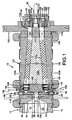
Fig. 1 is a sectional view of a food apparatus according to the preferred teachings of the present invention for forming multiple colored extrudates from a single extruder. -
Fig. 2 is a partial, exploded, perspective view of the apparatus ofFig. 1 . -
Fig. 3 is a cross sectional view of the apparatus ofFig. 2 according to section line 3-3 ofFig. 2 . -
Fig. 4 is a partial, top view of the apparatus ofFig. 2 . -
Fig. 5 is a bottom, perspective view the apparatus ofFig. 2 . - All figures are drawn for ease of explanation of the basic teachings of the present invention only; the extensions of the figures with respect to number, position, relationship, and dimensions of the parts to form the preferred embodiment will be explained or will be within the skill of the art after the following teachings of the present invention have been read and understood. Further, the exact dimensions and dimensional proportions to conform to specific force, weight, strength, and similar requirements will likewise be within the skill of the art after the following teachings of the present invention have been read and understood.
- Referring now to the drawing and briefly in particular to
Fig. 1 , there is shown anapparatus 10 for providing a multiplicity of mass substreams of a plastic food material from a single product mass main supply, with each of the streams having a mixed, non-homogenous color and/or flavor, according to the preferred teachings of the present invention. In the preferred form,apparatus 10 generally includes a means for providing at least one extrudable food product in a mass stream such as anextruder 12 and a head ormanifold 118. The present invention finds particular suitability for use in connection with the provision of cereal doughs and especially cooked cereal doughs for the production of RTE cereals or grain based snacks. While theextruder 12 preferably a cooker extruder, is the preferred equipment to provide the extrudable food, other conventional equipment and techniques can be employed. For example, a batch cooker or semi-continuous cooker for cooking the ingredients in bulk can be equipped with a dough forming and conveying extruder element. In other embodiments, e.g., a low moisture fruit paste or a pasta dough, a simple screw conveyor can be employed. - Moreover, while in the present description particular reference is made to the provision of multiple extrudates of farinaceous materials such as cooked cereal doughs for the preparation of RTE cereals, the skilled artisan will appreciate that the present apparatus and techniques can be employed with a wide variety of extrudable food products, especially such plastic foods as 1) low moisture fruit products, 2) uncooked cereal doughs such as for pasta, cookies, or breadstuffs, 3) potato doughs such as for fabricated potato snacks, 4) chewing gums, 5) cheeses and cheese products, or 6) yogurts.
- Extruder 12 can be any convenient type of food extruder for providing the extrudable food product. While single screw extruders are useful herein,
Fig. 1 shows the preferred embodiment wherein a twinscrew cooker extruder 12 is employed. In particular,extruder 12 can be seen to include anextruder barrel 13 having amain passageway 14. Disposed withinpassageway 14 is atwin screw auger 15 for advancing the extrudable food material through a discharge outlet, withtwin screw auger 15 in the preferred embodiment including a first and second or twin screw intermeshed flights. - According to the preferred teachings of the present invention,
apparatus 10 includes the head ormanifold 118 for dividing the dough stream ofextruder 12 into six substreams. In particular,manifold 118 includes anupstream face 80 and adownstream face 82. Manifold 118 is suitably secured to extruder 12 such as by the means shown withupstream face 80 abutting with the downstream face ofextruder 12. Manifold 118 includes a first frustoconical-shaped passage 84 which terminates in a cylindrical-shaped passage 86.Passage 84 extends fromface 80 towards but spaced fromface 82 and receives the extrudable food material being advanced bytwin screw auger 15.Passage 86 extends frompassage 84 towards but spaced fromface 82, withpassage 86 terminating approximately midway betweenfaces - Manifold 118 according to the preferred teachings of the present invention includes a plurality of radially extending, equally circumferentially spaced bores 88 extending from the outer periphery and intersecting with
passage 86. In the most preferred form, 6 bores 88 are provided. Manifold 118 further includes a plurality of axially extendingpassageways 90 extending fromface 82 and terminating in bores 88.Passageways 90 in the preferred form are arranged in a circular pattern onface 82, withpassageways 90 being equally circumferentially spaced. - Bores 88 are counterbored from the periphery of
manifold 118 to a point radially outward of the intersection withpassageways 90 for threadably receiving a cylindrical-shaped plug 92. Suitable means such as O-rings as shown can be provided for sealing betweenplugs 92 and bores 88 to prevent the escape of extrudable food material therebetween. The inner surfaces ofplugs 92 each threadably receive the stem 96 of arestrictor 98. The inner radial ends of stems 96 terminate in a pear-shapedhead 100. Suitable means such as O-rings as shown can be provided for sealing between stems 96 and the inner surfaces ofplugs 92 to prevent the escape of extrudable food material therebetween. - In the most preferred form, bores 88 each include a frustoconical-shaped
seat 104 adjacent to their interconnection topassage 86. It can then be appreciated that stems 96 can be rotated inplugs 92 to adjust the position ofhead 100 relative toseat 104 between an abutting position which prevents passage of extrudable food material frompassage 86 into bores 88 to a retracted position where extrudable food material is allowed to pass frompassage 86 into bores 88 and aroundhead 100. It should be appreciated that the further thathead 100 is withdrawn fromseat 104, the greater the rate of flow of the extrudable food material. Further, it should be appreciated that each of therestrictors 98 can be independently adjusted so that the flow of extrudable food material through each of the bores 88 can be adjusted. In the most preferred form, it is desired for the flow of extrudable food material to be generally equal through all of bores 88. - In the most preferred form, each
passageway 90 includes its own independentadditive supply 106.Supply 106 is in fluid communication with andmanifold 118 further includes means for adding the additive at multiple locations within the flow of extrudable food material such as adie insert 108 shown. In the preferred form, eachpassageway 90 includes anenlarged size counterbore 110 extending axially fromface 82 towards but spaced from bores 88 and at a distance generally equal to the axial length ofdie insert 108. In the most preferred form, dieinsert 108 is generally of the type shown and described inU.S. Patent No. 5,643,618 . In particular, dieinsert 108 includes means for imparting at least one and more desirably a plurality of dough interstitial gaps such as a plurality of dough dividing passageways formed by die dividing members. Dieinsert 108 can further include means for injecting the additive into the interstitial dough gaps such as a plurality of injection ports. Dieinsert 108 can further include asupply reservoir 119 supplied bysupply 106, withsupply reservoir 119 defined by the outer surface ofdie insert 108 andcounterbore 110, with suitable means such as O-rings preventing escape of the additive therebetween.Reservoir 119 is in fluid communication with the injection ports by suitable passageways extending through the die dividing members defining the dough dividing passageways. It should then be appreciated that the additive is not simply placed at the outer surface of the flow of extrudable food material but is placed through the entire area and more even mixing of the additive with the extrudable food material can occur. -
Apparatus 10 according to the teachings of the present invention further includes one or moremiddle segments 122 having a generally cylindrical outer surface in the most preferred form. Eachmiddle segment 122 includes a plurality of axially extendingsubpassageways 124 of a number, location, and arrangement corresponding topassageways 90.Subpassageways 124 have a size smaller than die inserts 108. The firstmiddle segment 122 is suitably secured tomanifold 118 such as by the means shown with the upstream face ofmiddle segment 122 abutting withdownstream face 82 ofmanifold 118. It can then be appreciated that dieinserts 108 are axially captured by being sandwiched between the upstream face ofmiddle segment 122 and the upstream axial end ofcounterbores 110. Eachsubpassageway 124 contains a number of stationary in-line static mixer or flight elements 59. - In the most preferred form, each
middle segment 122 is of a unique construction allowing access to static mixer elements 59. Specifically, in the most preferred form of the present invention,middle segment 122 is formed of a central plug 122a and anouter sleeve 122b. Central plug 122a has planar first and second ends, with the first end for abutment withdownstream face 82 ofmanifold 118. Central plug 122a further includes an outer frustoconical surface.Sleeve 122b has planar first and second ends, with the first end for abutment withdownstream face 82 ofmanifold 118.Sleeve 122b further includes an outer surface which is generally cylindrical in the preferred form and an inner frustoconical surface of a size and shape for slideably receiving and abutment with the outer frustoconical surface of central plug 122a. During the formation ofmiddle segment 122, central plug 122a is slideably received inouter sleeve 122b with the outer frustoconical surface of central plug 122a abutting with the inner frustoconical surface ofouter sleeve 122b.Subpassageways 124 which in the most preferred form are of a circular cross section are then bored or drilled with their axes generally located along the frustoconical surfaces of plug 122a andsleeve 122b so that generally half of each of thesubpassageways 124 is formed in plug 122a and the other half is formed insleeve 122b. It should then be appreciated that with the centers ofsubpassageways 124 located on the frustoconical surfaces of plugs 122a andsleeve 122b, the centers ofsubpassageways 124 have gradually decreasing spacing from the first ends to the second ends of plug 122a andsleeve 122b. - It should then be appreciated that in the event that one or more subpassageways 124 should become plugged, for example which could occur in the event of an extended power outage, it can be very difficult to nearly impossible to force the plugged dough with static mixer elements 59 axially through
subpassageways 124. According to the teachings of the present invention, withmiddle segment 122 removed fromapparatus 10, plug 122a can be forced out ofsleeve 122b such thatmiddle segment 122 is thus in two individual components. Typically, static mixer elements 59 and the plugged dough will remain in the halves ofsubpassageways 124 formed insleeve 122b. Access can then be obtained along the entire longitudinal lengths ofsubpassageways 124 by reaching in the open ends ofsleeve 122b or on the outer frustoconical surface of plug 122a. Thus, it can be appreciated that access is allowed to the interior ofsubpassageways 124, static mixer elements 59, and/or any dough located therein along the entire longitudinal lengths ofsubpassageways 124. Suitable handling bores can be provided in the ends of plug 122a to assist in the handling of plug 122a including when inserting or removing plug 122a fromsleeve 122b. It should further be appreciated that the frustoconical shape of the outer surface of plug 122a and the inner surface ofsleeve 122b is advantageous in creating increased spacing between such surfaces assleeve 122b is moved downstream relative to plug 122a during disassembly ofmiddle segment 122. Similarly, during operation ofapparatus 10, dough flowing throughsubpassageways 124 will tend to push plug 122a downstream relative tosleeve 122b to more firmly abut the frustoconical surfaces of plug 122a andsleeve 122b together. - Each
middle segment 122 includes first and second, axially spaced,annular shoulders 126 extending radially from the outer surface ofsleeve 122b.Shoulders 126 in the preferred form are located adjacent to but slightly axially inward of the axial ends ofmiddle segment 122 to allow securement ofmiddle segment 122 to upstream and downstream elements. Awater jacket 128 is partially formed by and held betweenshoulders 126 for circulation of a heat transfer medium such as water for adding heat tomiddle segment 122 and thus to the extrudable food material flowing throughsubpassageways 124 thereof. -
Apparatus 10 according to the preferred teachings of the present invention includes atransition plate 130 having a plurality of axially extendingbores 132 of a size, number, location, and arrangement corresponding to subpassageways 124 ofmiddle segments 122. Anadapter element 134 is suitably secured to transitionplate 130 such as by bolts extending throughelement 134 and threaded intoplate 130. The lastmiddle segment 122 is suitably secured toadaptor element 134 such as by the means shown with the downstream face ofmiddle section 122 abutting with the upstream face ofadapter element 134.Adapter element 134 includes a plurality of axially extendingbores 136 which can include wear sleeves of a size, number, location, arrangement, and extending betweenbores 132 andsubpassageways 124. - In
apparatus 10, diehead 30 is generally cup shaped and is suitably secured to the opposite side oftransition plate 130 thanadapter element 134 such as by the means shown. Dieports 40 are provided inouter die face 31. According to the teachings of the present invention, aregistration section 138 is provided having a shape and size corresponding to and for receipt withindie head 30.Section 138 includes connectingpassages 140 extending axially from and in communication withbores 132, with subpassages or connectingpassages 140 having an interior surface of corresponding shape and size asbores 132 and extend from the upstream face towards but spaced from the downstream face ofregistration section 138. Aninterconnecting passage 240 extends between the upstream and downstream faces and equally intersects adjacent pair of connectingpassages 140.Passages 240 are counterbored to define ashoulder 242 therein, generally intermediate the upstream and downstream faces ofregistration section 138. Eachpassage 240 is aligned with and in communication with anarcuate channel 243 at the downstream face ofregistration section 138. Eacharcuate channel 243 is arcuate in a plane parallel to but spaced from the upstream and downstream faces ofregistration section 138. A plurality ofdie ports 40 are in fluid communication with eacharcuate channel 243, with 18 dieports 40 provided in fluid communication with eachchannel 243 in the preferred form when threepassages 240 andchannels 243 are provided. -
Apparatus 10 according to the teachings of the present invention further includesstatic mixers 244 received inpassages 240 and in the preferred form are formed of two elements each of which is a KSM mixer marketed by Sulzer Chemtech. According to the teachings of the present invention,static mixers 244 have an operative length which is insufficient to provide homogenously colored dough streams such as performed by static mixer elements 59, but rather provides a random, non-homogenously colored dough stream and in the preferred form of a swirl.Static mixers 244 are received inpassages 240, abut withshoulders 242 and have an axial length spaced upstream from the downstream face ofregistration section 138. -
Apparatus 10 according to the teachings of the present invention further includes atransition element 246 corresponding to and slideably received in eachpassage 240. Eachtransition element 246 includes a plurality of sets of a plurality ofsubpassages 248 extending from the upstream face to the downstream face, with 4 sets each including 4subpassages 248 in series parallel to and in a symmetrical arrangement to a diameter oftransition element 246 extending through the axial centers ofadjacent bores 132 being shown in the preferred embodiment.Transition element 246 further includes a plurality ofchannels subpassages 248 extending from the upstream face towards but spaced from the downstream face, withchannels Channels transition element 246 and in communication with one of the pair of connectingpassages 140 but is not in communication with the other of the pair of connectingpassages 140. In the preferred form,channels transition element 246, andsubpassages 248 extend parallel to the peripheral edge oftransition element 246. In this regard,transition element 246 in the preferred form shown is symmetrical about a diameter interconnecting the axial centers of connectingpassages 140 in the preferred form shown. In the most preferred form, sets ofsubpassages 248 are arranged in a series parallel to the diameter interconnecting the axial center, with each series extending on both sides of an intersecting diameter extending perpendicular to the diameter interconnecting the axial centers of the pair of connectingpassages 140. - In the preferred form shown, the
center channels 250A adjacent the diameter interconnecting the axial centers of the pair ofpassages 140 generally extend parallel thereto. Eachcenter channel 250A includes afirst section 300 including first and second, spacedparallel walls 302 parallel to a diameter oftransition element 246 and extending from the peripheral edge oftransition element 246. Eachcenter channel 250A further includes asecond section 304 including asemi-cylindrical wall 306 extending between first andsecond walls 302 offirst section 300. Alast subpassage 248A of eachchannel 250A at a greatest spacing from the peripheral edge oftransition element 246 includes afirst portion 308 extending from the downstream face towards but spaced from the upstream face oftransition element 246.First portion 308 has oval cross sections parallel to the upstream and downstream faces. Eachsubpassage 248A further includes asecond portion 310 extending from upstream face to the downstream face and intersecting with the first portion.Section portion 310 has cross sections parallel to the upstream and downstream faces smaller than the oval cross sections offirst portion 308.Second portion 310 in the preferred form shown is eye-shaped and located in thesecond section 304. In the preferred form shown, first andsecond portions - The
outer channels 250B spaced outwardly of thecenter channels 250A are J-shaped and intersect with the peripheral edge oftransition element 246 such that theouter channels 250B are in part defined by connectingpassages 140.Transition elements 246 andstatic mixers 244 are sandwiched between the downstream face oftransition plate 130 and shoulders 242. - It should then be appreciated that
passages passageways 90, axially extendingbores ports 40 are generally contiguous and do not present shoulders or similar projections in the flow of extrudable food material to minimize buildup and hardening. Diehead 30 is suitably secured to transitionplate 130 such as by the means shown opposite toadapter element 134, withregistration section 138 sandwiched betweendie head 30 andtransition plate 130.Apparatus 10 further includes in the most preferred form shown a conventionalface rotary cutter 36 having at least onerotating cutter knife 38 for severing the extrudate ropes into individual pieces. - Operation of
apparatus 10 produces a number of dough substreams, with 6 being produced in the preferred form. It can then be appreciated that the admixed blend produced can be of two to six physical and/or compositional properties and/or at differing ratios. As an example,apparatus 10 could produce three dough substreams of red berry flavor, two dough substreams of purple grape flavor, and one dough substream of yellow lemon flavor. Specifically, product mass substreams are supplied frombores 132 into connectingpassages 140. Frompassages 140 in communication withadjacent bores 132, first and second product mass substreams are directed intochannels bores 132 and in the most preferred form generally perpendicular thereto. Fromchannels subpassages 248 oftransition element 246 located in interconnectingpassage 240. Fromsubpassages 248, the first and second product mass substreams are directed tostatic mixers 244. While passing throughstatic mixes 244, the first and second product mass substreams are mixed in a non-homogenous manner to create a swirl effect in the mixed mass stream. Afterstatic mixers 244, the mixed mass stream is directed from interconnectingpassage 240 intoarcuate channel 243 and then through dieports 40 in communication with interconnectingpassage 240 byarcuate channel 243, with the mixed mass stream being cut byknife 38 into individual pieces. - Thus since the invention disclosed herein may be embodied in other specific forms without departing from the general characteristics thereof, some of which forms have been indicated, the embodiments described herein are to be considered in all respects illustrative and not restrictive. The scope of the invention is to be indicated by the appended claims, rather than by the foregoing description.
Claims (15)
- An apparatus for producing a non-homogenously mixed extrudate, including means for supplying a first product mass substream disposed within a first subpassageway (124) having an interior surface and a second mass substream disposed within a second subpassageway (124) having an interior surface, an interconnecting passage (240) in communication with the first and second subpassageways (124), an exit port (40) in communication with the interconnecting passage (240), and a static mixer (244), characterized in that it comprises a transition element (246) including an upstream face, a downstream face, and a peripheral edge extending between the upstream and downstream faces, with the peripheral edge corresponding to and for slideable receipt in the interconnecting passage (240), first and second sets of subpassages (248) extending between the upstream and downstream faces of the transition element (246) a first and a second channels (250A) extending from the upstream face towards but spaced from the downstream face, with the first channel (250A) being in communication with the first subpassageway (124) and the first set of subpassages (248) but not with the second subpassageway (124) and the second set of subpassages (248), with the second channel (250A) being in communication with the second subpassageway (124) and the second set of subpassages (248) but not in communication with the first subpassageway (124) and the first set of subpassages (248), and with the static mixer (244) located in the interconnecting passage (240) intermediate the exit port (40) and the downstream face of the transition element (246).
- The apparatus of claim 1 wherein the interconnecting passage (240) includes a shoulder (242), with the first and second subpassageways (124) extending through a transition plate (130), with the transition element (246) and the static mixer (244) sandwiched between the shoulder (242) in the interconnecting passage (240) and the transition plate (130).
- The apparatus of claim 1 or 2 wherein each of the first and second sets of subpassages (248) include a plurality of subpassages (248).
- The apparatus of any preceding claim further including third and fourth channels (250B) extending from the upstream face towards but spaced from the downstream face and spaced from the first and second channels (250A), with the first and second channels (250A) located intermediate the third and fourth channels (250B), with the third and fourth channels (250B) being J-shaped parallel to the upstream and downstream faces and intersecting with the peripheral edge; and third and fourth sets of subpassages (248) extending between the upstream and downstream faces, with the third channel (250B) being in communication with the first subpassageway (124) and the third set of subpassages (248) but not with the second subpassageway (124) and the first, second, and fourth subpassages (248), with the fourth channel (250B) being in communication with the second subpassageway (124) and the fourth set of subpassages (248) but not in communication with the first subpassageway (124) and the first, second and third sets of subpassages (248).
- The apparatus of any preceding claim further including an arcuate channel (243) in communication with the interconnecting passage, with the arcuate channel (243) being arcuate in a plane parallel to but spaced from the upstream and downstream faces of the transition element (246), with the exit port (40) comprising a plurality of die ports (40) each in fluid communication with the arcuate channel (243).
- The apparatus of any preceding claim wherein the first and second channels (250A) extend parallel to the upstream and downstream faces of the transition element (246) and the first and second sets of subpassage (248) extend parallel to the peripheral edge of the transition element (246).
- The apparatus according to claim 3 wherein the plurality of subpassages (248) includes a last subpassage (248A) at a greatest spacing from the peripheral edge of the transition element (246), with the last subpassage (248A) including a first portion (308) extending from the downstream face towards but spaced from the upstream face, with the first portion (308) having oval cross sections parallel to the upstream and downstream faces, with the last subpassage (248A) including a second portion (310) extending from the upstream face to the downstream face, with the second portion (310) having cross sections parallel to the upstream and downstream faces smaller than the oval cross sections of the first portion (308), with the second portion (310) intersecting with the first portion (308).
- The apparatus of claim 7 wherein the first and second portions (308, 310) have a coextensive end surface.
- The apparatus of claim 7 or 8 wherein each of the first and second channels (250A) includes a first section (300) and a second section (304), with the first section (300) including first and second, spaced, parallel walls (302) parallel to the diameter and extending from the peripheral edge, with the second section (304) including a semi-cylindrical wall (306) extending between the first and second walls (302) of the first section (300), with the second portion (310) of the last subpassage (248A) located within the second section (304).
- The apparatus of any preceding claim wherein the first and second sets of subpassages (248) are symmetrical to a diameter of the transition element (246) extending between axial centers of the first and second subpassageways (124).
- Method for producing a non-homogenously mixed extradate comprising:supplying a first product mass substream;supplying a second product mass substream spaced and different from the first product mass substream;characterized bydirecting the first product mass substream into a first channel (250A) at a non- parallel angle to the first product mass substream;directing the first product mass substream from the first channel (250A) through a first set of spaced subpassages (248) in communication with a static mixer (244);directing the second product mass substream into a second channel (250A) at a non-parallel angle to the second product mass substeam; anddirecting the second product mass substream from the second channel (250A) through a second set of spaced subpassages (248) in communication with the static mixer (244), with the first channel (250A) not being in communication with the second channel (250A) and the second set of spaced subpassages (248), with the second channel (250A) not being in communication with the first channel (250A) and the first set of spaced subpassages (248).
- The method of claim 11 wherein supplying the first product mass substream comprises disposing the first product mass substream within a first subpassageway (124) having an interior surface; wherein supplying the second product mass substream comprises disposing the second product mass substream within a second subpassageway (124) having an interior surface; and wherein directing the first and second product mass substreams comprises providing an interconnection passage (240) in communication with the first and second subpassageways (124) and a transition element (246) including an upstream face, a downstream face, and a peripheral edge extending between the upstream and downstream faces, with the peripheral edge corresponding to and for slideable receipt in the interconnecting passage (240), with the first and second sets of subpassages (248) extending between the upstream and downstream faces of the transition element (246), with the first and second channels (250A) extending from the upstream face towards but spaced from the downstream face, with the first channel (250A) being in communication with the first subpassageway (124) and the first set of subpassages (248) but not with the second subpassageway (124) and the second set of subpassages (248), with the second channel (250A) being in communication with the second subpassageway (124) and the second set of subpassages (248) but not in
communication with the first subpassageway (124) and the first set of subpassages (248). - The method of any one of claims 11 or 12 wherein directing the first product mass substream comprises directing the first product mass substream into the first channel (250A) and a third channel (250B); wherein directing the second product mass substream comprises directing the second product mass substream into the second channel (250A) and a fourth channel (250B), with the third and fourth channels (250B) extending from the upstream face towards but spaced from the downstream face and spaced from the first and second channels (250A), with the first and second channels (250A) located intermediate the third and fourth channels (250B), with the third and fourth channels (250B) being J-shaped parallel to the upstream and downstream faces and intersecting with the peripheral edge; wherein the method further comprises directing the first product mass substream from the third channel (250B) through a third set of spaced subpassages (248); and directing the second product mass substream from the fourth channel (250B) through a fourth set of spaced subpassages (248), with the third and fourth sets of subpassages (248) extending between the upstream and downstream faces, with the third channel (250B) being in communication with the first subpassageway (124) and the third set of subpassages (248) but not with the second subpassageway (124) and the first, second, and fourth subpassages (248), with the fourth channel (250B) being in communication with the second subpassageway (124) and the fourth set of subpassages (248) but not in communication with the first subpassageway (124) and the first, second and third sets of subpassages (248).
- The method of any one of claims 11-13 wherein directing the first product mass substream comprises directing the first product mass substream into the first channel (250) including a first section (300) and a second section (304), with the first section (300) including first and second, spaced, parallel walls (302) parallel to the direction and extending from the peripheral edge, with the second section (314) including a semi-cylindrical wall (306) extending between the first and second walls (302) of the first section (300).
- The method of claim 14 wherein directing the first product mass substream comprises directing the first product mass substream through the first set of spaced subpassages (248) including a last subpassage (248A) at a greatest spacing from the peripheral edge of the transition element (246), with the last subpassage (248A) including a first portion (308) extending from the downstream face towards but spaced from the upstream face, with the first portion (308) having oval cross sections parallel to the upstream and downstream faces, with the last subpassage (248A) including a second portion (310) extending from the upstream face to the downstream face, with the second portion (310) having cross sections parallel to the upstream and downstream faces smaller than the oval cross sections of the first portion (308), with the second portion (310) intersecting with the first portion (308), with the second portion (310) of the last subpassage (248A) located within the second section (304).
Applications Claiming Priority (2)
| Application Number | Priority Date | Filing Date | Title |
|---|---|---|---|
| US12/758,441 US8287262B2 (en) | 2010-04-12 | 2010-04-12 | Methods and apparatus for producing multiple food extrudates |
| PCT/US2011/027103 WO2011129924A1 (en) | 2010-04-12 | 2011-03-04 | Methods and apparatus for producing multiple food extrudates |
Publications (3)
| Publication Number | Publication Date |
|---|---|
| EP2557945A1 EP2557945A1 (en) | 2013-02-20 |
| EP2557945A4 EP2557945A4 (en) | 2015-02-18 |
| EP2557945B1 true EP2557945B1 (en) | 2016-08-03 |
Family
ID=44761110
Family Applications (1)
| Application Number | Title | Priority Date | Filing Date |
|---|---|---|---|
| EP11769237.6A Active EP2557945B1 (en) | 2010-04-12 | 2011-03-04 | Methods and apparatus for producing multiple food extrudates |
Country Status (11)
| Country | Link |
|---|---|
| US (2) | US8287262B2 (en) |
| EP (1) | EP2557945B1 (en) |
| AU (1) | AU2011241035B2 (en) |
| CA (1) | CA2734906C (en) |
| CL (1) | CL2012002878A1 (en) |
| ES (1) | ES2599825T3 (en) |
| MX (1) | MX2012011967A (en) |
| MY (1) | MY183699A (en) |
| PH (1) | PH12012502055A1 (en) |
| PL (1) | PL2557945T3 (en) |
| WO (1) | WO2011129924A1 (en) |
Families Citing this family (3)
| Publication number | Priority date | Publication date | Assignee | Title |
|---|---|---|---|---|
| CN105410097B (en) * | 2015-12-29 | 2018-03-13 | 成都松川雷博机械设备有限公司 | The multiple fillings shaped device of annular station |
| CN107455787B (en) * | 2017-10-10 | 2023-11-10 | 广州市国研机械设备制造有限公司 | Extrusion mechanism for flour or bean products |
| WO2021154918A1 (en) | 2020-01-29 | 2021-08-05 | Over The Top Foods Inc. | Dispensation devices and methods of manufacture and use thereof |
Family Cites Families (20)
| Publication number | Priority date | Publication date | Assignee | Title |
|---|---|---|---|---|
| FR2110666A5 (en) | 1970-10-26 | 1972-06-02 | Clair Bernard Savonnerie | |
| CA1145192A (en) * | 1980-02-06 | 1983-04-26 | General Foods, Inc. | Soft-moist pet food and process |
| US4542686A (en) * | 1983-11-08 | 1985-09-24 | The Quaker Oats Company | Method and apparatus for making a marbled pet food |
| US5110276A (en) * | 1989-12-28 | 1992-05-05 | Farnsworth John T | Extrusion die assembly |
| US5643618A (en) | 1994-05-11 | 1997-07-01 | General Mills, Inc. | Apparatus for making multiple, complexly patterned extrudates |
| US5639485A (en) | 1994-05-11 | 1997-06-17 | General Mills, Inc. | Apparatus for making a complexly patterned extrudate |
| US5752364A (en) | 1996-03-11 | 1998-05-19 | General Mills, Inc. | Food item fabricating apparatus and methods |
| US5776534A (en) | 1996-04-03 | 1998-07-07 | General Mills, Inc. | Food apparatus for forming multiple colored extrudates and method of preparation |
| US5759603A (en) * | 1996-11-15 | 1998-06-02 | Kellogg Company | Process for producing a food product having a distinct phase |
| US5843503A (en) | 1997-02-24 | 1998-12-01 | General Mills, Inc. | Apparatus and method for making multiple patterned extrudates |
| US5919509A (en) | 1997-05-01 | 1999-07-06 | General Mills, Inc. | Method and apparatus for producing multiple food extrudates |
| US6251452B1 (en) | 1999-04-23 | 2001-06-26 | General Mills, Inc. | Apparatus and methods for making multiple, complexly patterned extrudates |
| US6167798B1 (en) * | 2000-04-19 | 2001-01-02 | General Mills, Inc. | Cooker die and rotary cutter removably securing mechanism |
| US6189439B1 (en) | 2000-05-25 | 2001-02-20 | General Mills, Inc. | Cooker die and rotary cutter removably securing mechanism |
| US6509049B1 (en) * | 2000-06-16 | 2003-01-21 | The Quaker Oats Company | Device system and method for fluid additive injection into a viscous fluid food stream |
| US7648352B2 (en) * | 2001-10-29 | 2010-01-19 | Frito-Lay North America, Inc. | Apparatus for imprinting lines on direct-expanded food products having complex shapes with improved dimensional quality |
| US20040156954A1 (en) | 2003-02-07 | 2004-08-12 | Peeyush Maheshwari | Crisp microwaveable filled dough product, and methods for making same |
| US7320583B2 (en) | 2003-04-16 | 2008-01-22 | Frito-Lay North America, Inc | Apparatus and method for producing colored extruded food products |
| CA2659409C (en) | 2006-09-29 | 2014-05-20 | General Mills, Inc. | Apparatus and methods for fabricating food items |
| US20080089989A1 (en) | 2006-10-11 | 2008-04-17 | The Quaker Oats Company, Inc. | Apparatus with flow divider and method for making multicolored cereal |
-
2010
- 2010-04-12 US US12/758,441 patent/US8287262B2/en active Active
-
2011
- 2011-03-04 PH PH1/2012/502055A patent/PH12012502055A1/en unknown
- 2011-03-04 EP EP11769237.6A patent/EP2557945B1/en active Active
- 2011-03-04 ES ES11769237.6T patent/ES2599825T3/en active Active
- 2011-03-04 PL PL11769237T patent/PL2557945T3/en unknown
- 2011-03-04 WO PCT/US2011/027103 patent/WO2011129924A1/en not_active Ceased
- 2011-03-04 MX MX2012011967A patent/MX2012011967A/en active IP Right Grant
- 2011-03-04 MY MYPI2012004584A patent/MY183699A/en unknown
- 2011-03-04 AU AU2011241035A patent/AU2011241035B2/en active Active
- 2011-03-23 CA CA2734906A patent/CA2734906C/en active Active
-
2012
- 2012-09-26 US US13/627,409 patent/US9028733B2/en active Active
- 2012-10-12 CL CL2012002878A patent/CL2012002878A1/en unknown
Non-Patent Citations (1)
| Title |
|---|
| None * |
Also Published As
| Publication number | Publication date |
|---|---|
| AU2011241035A1 (en) | 2012-11-08 |
| MX2012011967A (en) | 2013-03-05 |
| PH12012502055A1 (en) | 2016-01-22 |
| AU2011241035A9 (en) | 2013-01-24 |
| PL2557945T3 (en) | 2017-02-28 |
| BR112012026384A2 (en) | 2015-09-15 |
| US9028733B2 (en) | 2015-05-12 |
| EP2557945A1 (en) | 2013-02-20 |
| CA2734906C (en) | 2016-10-18 |
| EP2557945A4 (en) | 2015-02-18 |
| ES2599825T3 (en) | 2017-02-03 |
| WO2011129924A1 (en) | 2011-10-20 |
| MY183699A (en) | 2021-03-08 |
| CL2012002878A1 (en) | 2013-12-06 |
| US20130022726A1 (en) | 2013-01-24 |
| US20110250337A1 (en) | 2011-10-13 |
| AU2011241035B2 (en) | 2016-07-07 |
| CA2734906A1 (en) | 2011-10-12 |
| US8287262B2 (en) | 2012-10-16 |
Similar Documents
| Publication | Publication Date | Title |
|---|---|---|
| US5919509A (en) | Method and apparatus for producing multiple food extrudates | |
| US5776534A (en) | Food apparatus for forming multiple colored extrudates and method of preparation | |
| EP0434983B1 (en) | Extrusion die assembly | |
| US7820215B2 (en) | Apparatus and method for producing colored extruded food products | |
| US5120554A (en) | Method for producing extruded center filled products | |
| AU733521B2 (en) | Apparatus and methods for making multiple, patterned extrudates | |
| AU2005282831B2 (en) | Apparatus and method for improving the dimensional quality of extruded food products having complex shapes | |
| CA2302654C (en) | Extrusion die | |
| CZ200155A3 (en) | A method of coextruding with coextrusion channels | |
| US5165949A (en) | Process for producing extruded food products | |
| US9028733B2 (en) | Methods for producing multiple food extrudates | |
| MXPA06000592A (en) | Apparatus and method for imprinting lines on direct-expanded food products having complex shapes with improved dimensional quality. | |
| JPH1057037A (en) | Partial mixing of food material and apparatus therefor | |
| EP0726718B1 (en) | Process for preparing pretzel chips | |
| EP1262106B1 (en) | Extruded expanded cereal shaped as an array of touching balls | |
| BR112012026384B1 (en) | METHODS AND APPARATUS FOR PRODUCTION OF MULTIPLE FOOD EXTRUSIONS | |
| KR20000000711A (en) | Manufacturing method of super food | |
| MXPA99007753A (en) | Apparatus and methods for making multiple, patterned extrudates |
Legal Events
| Date | Code | Title | Description |
|---|---|---|---|
| PUAI | Public reference made under article 153(3) epc to a published international application that has entered the european phase |
Free format text: ORIGINAL CODE: 0009012 |
|
| 17P | Request for examination filed |
Effective date: 20121107 |
|
| AK | Designated contracting states |
Kind code of ref document: A1 Designated state(s): AL AT BE BG CH CY CZ DE DK EE ES FI FR GB GR HR HU IE IS IT LI LT LU LV MC MK MT NL NO PL PT RO RS SE SI SK SM TR |
|
| DAX | Request for extension of the european patent (deleted) | ||
| A4 | Supplementary search report drawn up and despatched |
Effective date: 20150120 |
|
| RIC1 | Information provided on ipc code assigned before grant |
Ipc: A23L 1/164 20060101ALI20150114BHEP Ipc: A23P 1/12 20060101AFI20150114BHEP Ipc: A21C 11/16 20060101ALI20150114BHEP Ipc: A23L 1/00 20060101ALI20150114BHEP |
|
| 17Q | First examination report despatched |
Effective date: 20150717 |
|
| REG | Reference to a national code |
Ref country code: DE Ref legal event code: R079 Ref document number: 602011028828 Country of ref document: DE Free format text: PREVIOUS MAIN CLASS: A23P0001120000 Ipc: A21C0011160000 |
|
| GRAP | Despatch of communication of intention to grant a patent |
Free format text: ORIGINAL CODE: EPIDOSNIGR1 |
|
| RIC1 | Information provided on ipc code assigned before grant |
Ipc: A23G 4/04 20060101ALI20160112BHEP Ipc: A21C 11/16 20060101AFI20160112BHEP |
|
| INTG | Intention to grant announced |
Effective date: 20160204 |
|
| GRAR | Information related to intention to grant a patent recorded |
Free format text: ORIGINAL CODE: EPIDOSNIGR71 |
|
| GRAS | Grant fee paid |
Free format text: ORIGINAL CODE: EPIDOSNIGR3 |
|
| GRAA | (expected) grant |
Free format text: ORIGINAL CODE: 0009210 |
|
| INTG | Intention to grant announced |
Effective date: 20160623 |
|
| AK | Designated contracting states |
Kind code of ref document: B1 Designated state(s): AL AT BE BG CH CY CZ DE DK EE ES FI FR GB GR HR HU IE IS IT LI LT LU LV MC MK MT NL NO PL PT RO RS SE SI SK SM TR |
|
| REG | Reference to a national code |
Ref country code: GB Ref legal event code: FG4D |
|
| REG | Reference to a national code |
Ref country code: CH Ref legal event code: EP Ref country code: AT Ref legal event code: REF Ref document number: 816735 Country of ref document: AT Kind code of ref document: T Effective date: 20160815 |
|
| REG | Reference to a national code |
Ref country code: IE Ref legal event code: FG4D |
|
| REG | Reference to a national code |
Ref country code: DE Ref legal event code: R096 Ref document number: 602011028828 Country of ref document: DE |
|
| REG | Reference to a national code |
Ref country code: NL Ref legal event code: MP Effective date: 20160803 |
|
| REG | Reference to a national code |
Ref country code: LT Ref legal event code: MG4D |
|
| REG | Reference to a national code |
Ref country code: AT Ref legal event code: MK05 Ref document number: 816735 Country of ref document: AT Kind code of ref document: T Effective date: 20160803 |
|
| PG25 | Lapsed in a contracting state [announced via postgrant information from national office to epo] |
Ref country code: HR Free format text: LAPSE BECAUSE OF FAILURE TO SUBMIT A TRANSLATION OF THE DESCRIPTION OR TO PAY THE FEE WITHIN THE PRESCRIBED TIME-LIMIT Effective date: 20160803 Ref country code: LT Free format text: LAPSE BECAUSE OF FAILURE TO SUBMIT A TRANSLATION OF THE DESCRIPTION OR TO PAY THE FEE WITHIN THE PRESCRIBED TIME-LIMIT Effective date: 20160803 Ref country code: NL Free format text: LAPSE BECAUSE OF FAILURE TO SUBMIT A TRANSLATION OF THE DESCRIPTION OR TO PAY THE FEE WITHIN THE PRESCRIBED TIME-LIMIT Effective date: 20160803 Ref country code: RS Free format text: LAPSE BECAUSE OF FAILURE TO SUBMIT A TRANSLATION OF THE DESCRIPTION OR TO PAY THE FEE WITHIN THE PRESCRIBED TIME-LIMIT Effective date: 20160803 Ref country code: NO Free format text: LAPSE BECAUSE OF FAILURE TO SUBMIT A TRANSLATION OF THE DESCRIPTION OR TO PAY THE FEE WITHIN THE PRESCRIBED TIME-LIMIT Effective date: 20161103 Ref country code: FI Free format text: LAPSE BECAUSE OF FAILURE TO SUBMIT A TRANSLATION OF THE DESCRIPTION OR TO PAY THE FEE WITHIN THE PRESCRIBED TIME-LIMIT Effective date: 20160803 Ref country code: IS Free format text: LAPSE BECAUSE OF FAILURE TO SUBMIT A TRANSLATION OF THE DESCRIPTION OR TO PAY THE FEE WITHIN THE PRESCRIBED TIME-LIMIT Effective date: 20161203 |
|
| REG | Reference to a national code |
Ref country code: ES Ref legal event code: FG2A Ref document number: 2599825 Country of ref document: ES Kind code of ref document: T3 Effective date: 20170203 |
|
| PG25 | Lapsed in a contracting state [announced via postgrant information from national office to epo] |
Ref country code: LV Free format text: LAPSE BECAUSE OF FAILURE TO SUBMIT A TRANSLATION OF THE DESCRIPTION OR TO PAY THE FEE WITHIN THE PRESCRIBED TIME-LIMIT Effective date: 20160803 Ref country code: PT Free format text: LAPSE BECAUSE OF FAILURE TO SUBMIT A TRANSLATION OF THE DESCRIPTION OR TO PAY THE FEE WITHIN THE PRESCRIBED TIME-LIMIT Effective date: 20161205 Ref country code: SE Free format text: LAPSE BECAUSE OF FAILURE TO SUBMIT A TRANSLATION OF THE DESCRIPTION OR TO PAY THE FEE WITHIN THE PRESCRIBED TIME-LIMIT Effective date: 20160803 Ref country code: GR Free format text: LAPSE BECAUSE OF FAILURE TO SUBMIT A TRANSLATION OF THE DESCRIPTION OR TO PAY THE FEE WITHIN THE PRESCRIBED TIME-LIMIT Effective date: 20161104 Ref country code: AT Free format text: LAPSE BECAUSE OF FAILURE TO SUBMIT A TRANSLATION OF THE DESCRIPTION OR TO PAY THE FEE WITHIN THE PRESCRIBED TIME-LIMIT Effective date: 20160803 |
|
| REG | Reference to a national code |
Ref country code: FR Ref legal event code: PLFP Year of fee payment: 7 |
|
| PG25 | Lapsed in a contracting state [announced via postgrant information from national office to epo] |
Ref country code: EE Free format text: LAPSE BECAUSE OF FAILURE TO SUBMIT A TRANSLATION OF THE DESCRIPTION OR TO PAY THE FEE WITHIN THE PRESCRIBED TIME-LIMIT Effective date: 20160803 Ref country code: RO Free format text: LAPSE BECAUSE OF FAILURE TO SUBMIT A TRANSLATION OF THE DESCRIPTION OR TO PAY THE FEE WITHIN THE PRESCRIBED TIME-LIMIT Effective date: 20160803 |
|
| REG | Reference to a national code |
Ref country code: DE Ref legal event code: R097 Ref document number: 602011028828 Country of ref document: DE |
|
| PG25 | Lapsed in a contracting state [announced via postgrant information from national office to epo] |
Ref country code: DK Free format text: LAPSE BECAUSE OF FAILURE TO SUBMIT A TRANSLATION OF THE DESCRIPTION OR TO PAY THE FEE WITHIN THE PRESCRIBED TIME-LIMIT Effective date: 20160803 Ref country code: CZ Free format text: LAPSE BECAUSE OF FAILURE TO SUBMIT A TRANSLATION OF THE DESCRIPTION OR TO PAY THE FEE WITHIN THE PRESCRIBED TIME-LIMIT Effective date: 20160803 Ref country code: BE Free format text: LAPSE BECAUSE OF FAILURE TO SUBMIT A TRANSLATION OF THE DESCRIPTION OR TO PAY THE FEE WITHIN THE PRESCRIBED TIME-LIMIT Effective date: 20160803 Ref country code: BG Free format text: LAPSE BECAUSE OF FAILURE TO SUBMIT A TRANSLATION OF THE DESCRIPTION OR TO PAY THE FEE WITHIN THE PRESCRIBED TIME-LIMIT Effective date: 20161103 Ref country code: SK Free format text: LAPSE BECAUSE OF FAILURE TO SUBMIT A TRANSLATION OF THE DESCRIPTION OR TO PAY THE FEE WITHIN THE PRESCRIBED TIME-LIMIT Effective date: 20160803 Ref country code: SM Free format text: LAPSE BECAUSE OF FAILURE TO SUBMIT A TRANSLATION OF THE DESCRIPTION OR TO PAY THE FEE WITHIN THE PRESCRIBED TIME-LIMIT Effective date: 20160803 |
|
| PLBE | No opposition filed within time limit |
Free format text: ORIGINAL CODE: 0009261 |
|
| STAA | Information on the status of an ep patent application or granted ep patent |
Free format text: STATUS: NO OPPOSITION FILED WITHIN TIME LIMIT |
|
| 26N | No opposition filed |
Effective date: 20170504 |
|
| PG25 | Lapsed in a contracting state [announced via postgrant information from national office to epo] |
Ref country code: SI Free format text: LAPSE BECAUSE OF FAILURE TO SUBMIT A TRANSLATION OF THE DESCRIPTION OR TO PAY THE FEE WITHIN THE PRESCRIBED TIME-LIMIT Effective date: 20160803 |
|
| REG | Reference to a national code |
Ref country code: CH Ref legal event code: PL |
|
| PG25 | Lapsed in a contracting state [announced via postgrant information from national office to epo] |
Ref country code: MC Free format text: LAPSE BECAUSE OF FAILURE TO SUBMIT A TRANSLATION OF THE DESCRIPTION OR TO PAY THE FEE WITHIN THE PRESCRIBED TIME-LIMIT Effective date: 20160803 |
|
| REG | Reference to a national code |
Ref country code: IE Ref legal event code: MM4A |
|
| PG25 | Lapsed in a contracting state [announced via postgrant information from national office to epo] |
Ref country code: LU Free format text: LAPSE BECAUSE OF NON-PAYMENT OF DUE FEES Effective date: 20170304 |
|
| PG25 | Lapsed in a contracting state [announced via postgrant information from national office to epo] |
Ref country code: IE Free format text: LAPSE BECAUSE OF NON-PAYMENT OF DUE FEES Effective date: 20170304 Ref country code: LI Free format text: LAPSE BECAUSE OF NON-PAYMENT OF DUE FEES Effective date: 20170331 Ref country code: CH Free format text: LAPSE BECAUSE OF NON-PAYMENT OF DUE FEES Effective date: 20170331 |
|
| REG | Reference to a national code |
Ref country code: FR Ref legal event code: PLFP Year of fee payment: 8 |
|
| PG25 | Lapsed in a contracting state [announced via postgrant information from national office to epo] |
Ref country code: MT Free format text: LAPSE BECAUSE OF NON-PAYMENT OF DUE FEES Effective date: 20170304 |
|
| PG25 | Lapsed in a contracting state [announced via postgrant information from national office to epo] |
Ref country code: AL Free format text: LAPSE BECAUSE OF FAILURE TO SUBMIT A TRANSLATION OF THE DESCRIPTION OR TO PAY THE FEE WITHIN THE PRESCRIBED TIME-LIMIT Effective date: 20160803 |
|
| PG25 | Lapsed in a contracting state [announced via postgrant information from national office to epo] |
Ref country code: HU Free format text: LAPSE BECAUSE OF FAILURE TO SUBMIT A TRANSLATION OF THE DESCRIPTION OR TO PAY THE FEE WITHIN THE PRESCRIBED TIME-LIMIT; INVALID AB INITIO Effective date: 20110304 |
|
| PG25 | Lapsed in a contracting state [announced via postgrant information from national office to epo] |
Ref country code: CY Free format text: LAPSE BECAUSE OF NON-PAYMENT OF DUE FEES Effective date: 20160803 |
|
| PG25 | Lapsed in a contracting state [announced via postgrant information from national office to epo] |
Ref country code: MK Free format text: LAPSE BECAUSE OF FAILURE TO SUBMIT A TRANSLATION OF THE DESCRIPTION OR TO PAY THE FEE WITHIN THE PRESCRIBED TIME-LIMIT Effective date: 20160803 |
|
| P01 | Opt-out of the competence of the unified patent court (upc) registered |
Effective date: 20230530 |
|
| PGFP | Annual fee paid to national office [announced via postgrant information from national office to epo] |
Ref country code: ES Payment date: 20250416 Year of fee payment: 15 |
|
| PGFP | Annual fee paid to national office [announced via postgrant information from national office to epo] |
Ref country code: GB Payment date: 20260219 Year of fee payment: 16 |
|
| PGFP | Annual fee paid to national office [announced via postgrant information from national office to epo] |
Ref country code: DE Payment date: 20260219 Year of fee payment: 16 |
|
| PGFP | Annual fee paid to national office [announced via postgrant information from national office to epo] |
Ref country code: IT Payment date: 20260219 Year of fee payment: 16 |
|
| PGFP | Annual fee paid to national office [announced via postgrant information from national office to epo] |
Ref country code: FR Payment date: 20260219 Year of fee payment: 16 |
|
| PGFP | Annual fee paid to national office [announced via postgrant information from national office to epo] |
Ref country code: TR Payment date: 20260223 Year of fee payment: 16 |
|
| PGFP | Annual fee paid to national office [announced via postgrant information from national office to epo] |
Ref country code: PL Payment date: 20260304 Year of fee payment: 16 |