EP2557638A1 - Level-type connector and method of assembling it - Google Patents
Level-type connector and method of assembling it Download PDFInfo
- Publication number
- EP2557638A1 EP2557638A1 EP12005124A EP12005124A EP2557638A1 EP 2557638 A1 EP2557638 A1 EP 2557638A1 EP 12005124 A EP12005124 A EP 12005124A EP 12005124 A EP12005124 A EP 12005124A EP 2557638 A1 EP2557638 A1 EP 2557638A1
- Authority
- EP
- European Patent Office
- Prior art keywords
- cam
- lever
- cam groove
- pin
- groove
- Prior art date
- Legal status (The legal status is an assumption and is not a legal conclusion. Google has not performed a legal analysis and makes no representation as to the accuracy of the status listed.)
- Granted
Links
Images




Classifications
-
- H—ELECTRICITY
- H01—ELECTRIC ELEMENTS
- H01R—ELECTRICALLY-CONDUCTIVE CONNECTIONS; STRUCTURAL ASSOCIATIONS OF A PLURALITY OF MUTUALLY-INSULATED ELECTRICAL CONNECTING ELEMENTS; COUPLING DEVICES; CURRENT COLLECTORS
- H01R13/00—Details of coupling devices of the kinds covered by groups H01R12/70 or H01R24/00 - H01R33/00
- H01R13/62—Means for facilitating engagement or disengagement of coupling parts or for holding them in engagement
- H01R13/629—Additional means for facilitating engagement or disengagement of coupling parts, e.g. aligning or guiding means, levers, gas pressure electrical locking indicators, manufacturing tolerances
- H01R13/62933—Comprising exclusively pivoting lever
- H01R13/62938—Pivoting lever comprising own camming means
Definitions
- the present invention relates to a lever-type connector and to a method of assembling it.
- a conventional lever-type connector is disclosed in Japanese Unexamined Patent Publication No. 2008-130244 .
- This includes a pair of male and female connector housings connectable to each other and a lever rotatably supported on the female connector housing.
- a moving plate to be pushed by the female connector housing in the process of connecting the two connector housings is assembled into the male connector housing.
- a divided cam pin is formed to project from the moving plate and another divided pin is formed to project from the female connector housing. Further, a cam groove is formed to extend in the lever.
- the both divided cam pins are united with each other, thereby forming a cylindrical cam pin, and this cam pin slides along a groove surface of the cam groove to effect cam action as the lever is rotated, whereby a connecting operation of the two connector housings proceeds.
- the present invention was completed in view of the above situation and an object thereof is to increase the strength of a cam pin without enlarging a connector.
- a lever-type connector comprising a lever which is formed with an extending cam groove; a first connector housing on which the lever is displaceably or movably (particularly rotatably or pivotably) supported; and a second connector housing which is connectable to the first connector housing and from which a cam pin projects; the cam pin being inserted into the cam groove and, in that state, the lever being displaced or moved (particularly rotated or pivoted), whereby the cam pin substantially slides along a groove surface of the cam groove to effect cam action and an operation of connecting the first and second connector housings proceeds, wherein a part of the cam pin to be inserted into the cam groove is long in an extending direction of the cam groove and short in a groove width direction perpendicular to the extending direction of the cam groove.
- the strength of the cam pin is ensured to be high by thickening parts long in the extending direction of the cam groove and an increase in the width of the cam groove is prevented by inserting the parts short in the groove width direction of the cam groove into the cam groove.
- the strength of the cam pin can be increased without enlarging the connector.
- the part of the cam pin to be inserted into the cam groove is in the form of a solid cylinder.
- the part of the cam pin to be inserted into the cam groove is formed with at least one hollowed portion.
- the part of the cam pin to be inserted into the cam groove is formed with the hollowed portion, formation of sinks can be prevented and shape accuracy of the cam pin can be improved.
- the part of the cam pin to be inserted into the cam groove has an oval outer shape long in the extending direction of the cam groove.
- the part of the cam pin to be inserted into the cam groove has the oval outer shape long in the extending direction of the cam groove, curved surfaces of the cam pin and the cam groove slide along each other, wherefore sliding stability is excellent.
- the part of the cam pin to be inserted into the cam groove has a polygonal outer shape long in the extending direction of the cam groove.
- the strength of the cam pin is further increased by thickened angular parts.
- the cam pin comprises at least one projecting piece projecting radially outwardly from a projecting end of the part of the cam pin to be inserted into the cam groove.
- a dimension of the part of the cam pin to be inserted into the cam groove in a shorter side direction corresponds to the width of the cam groove.
- the part of the cam pin to be inserted into the cam groove is formed to have substantially the same configuration over the entire height.
- a method of assembling a lever-type connector comprising the following steps: displaceably or movably mounting a lever formed with at least one extending cam groove on a first connector housing; and connecting a second connector housing from which at least one cam pin projects to the first connector housing such that the cam pin is at least partly inserted into the cam groove and, in that state, displacing the lever, whereby the cam pin slides along a groove surface of the cam groove to effect cam action and an operation of connecting the first and second connector housings proceeds, wherein a part of the cam pin inserted into the cam groove is configured such as to be long in an extending direction of the cam groove and short in a groove width direction perpendicular to the extending direction of the cam groove.
- a lever-type connector 10 includes first and second connector housings 20, 40 connectable to each other along a connecting direction CD and a lever 60 to be displaceably (particularly rotatably or pivotably) mounted on the first connector housing 20.
- the first connector housing 20 is made e.g. of synthetic resin and, as shown in FIG. 1 , includes a housing main body 21 (particularly substantially in the form of a rectangular block long in a width direction) and a (particularly substantially cap-shaped) wire cover 22 to be mounted on (particularly a rear end part of) the housing main body 21.
- a housing main body 21 particularly substantially in the form of a rectangular block long in a width direction
- a (particularly substantially cap-shaped) wire cover 22 to be mounted on (particularly a rear end part of) the housing main body 21.
- One or more, particularly a plurality of unillustrated female terminal fittings are to be at least partly accommodated in the housing main body 21 and connected to one or more respective end portions of unillustrated wires.
- Each wire is to be pulled out from the rear surface of the housing main body 21, at least partly accommodated in a bent state in the wire cover 22 and drawn out to the outside through an opening at one widthwise side of the wire cover 22.
- One or more, particularly a pair of supporting shafts 23 are formed to project from one or more widthwise intermediate parts of one or more side surfaces of the housing main body 21, particularly from substantially widthwise central parts of both side surfaces of the housing main body 21.
- the (both) supporting shaft(s) 23 particularly has/have a substantially cylindrical shape and form rotary shafts for the lever 60.
- the lever 60 (as a particular movable member) is made e.g. of synthetic resin and/or particularly substantially gate-shaped and includes an operating portion 61 and one or more, particularly a pair of arm portions 62 particularly projecting substantially in parallel from both ends of the operating portion 61.
- the lever 60 particularly is to be mounted from behind to straddle the first connector housing 20 and the both arm portions 62 are arranged at the outer sides of the both side surfaces of the housing main body 21 when the lever 60 is mounted.
- One or more, particularly a pair of cam grooves 63 extending in a curved manner in a specified (predetermined or predeterminable) direction ED and one or more (particularly substantially circular) bearing holes 64 are formed to penetrate through the (both) arm portion(s) 62.
- the supporting shaft(s) 23 is/are to be at least partly fitted and inserted into the bearing hole(s) 64 of the (particularly both) arm portion(s) 62.
- a lever 60 is displaceable (particularly rotatable or pivotable) about the supporting shaft(s) 23 between an initial position IP where the operating portion 61 particularly is located on the other widthwise side of the first connector housing 20 and a connection position CP where the operating portion 61 particularly is located at one widthwise side of the first connector housing 20.
- the (both) arm portion(s) 62 is/are (each) formed with an introducing groove 65 communicating with the entrance of the cam groove 63, and the introducing groove(s) 65 is/are arranged to substantially face forward at the initial position IP.
- the second connector housing 40 is made e.g. of synthetic resin and, as shown in FIG. 1 , includes a receptacle 41 particularly substantially in the form of a rectangular tube long in the width direction.
- a receptacle 41 particularly substantially in the form of a rectangular tube long in the width direction.
- One or more, particularly a plurality of unillustrated male terminal fittings are arranged to project into the receptacle 41.
- the (particularly each) male terminal fitting is to be electrically conductively connected to the corresponding female terminal fitting as the first and second connector housings 20, 40 are connected.
- the cam pin 43 is composed of or comprises a solid and substantially cylindrical pin main body 45 and one or more, particularly a pair of projecting pieces 46 projecting radially outwardly from (particularly substantially opposite radial ends of) the projecting end of the pin main body 45.
- the pin main body 45 substantially has an oval cross-section, specifically an elliptical cross-section and/or is formed to have substantially the same diameter over the entire height.
- the pin main body 45 has an elliptical outer shape long in the width direction (direction perpendicular to the connecting direction CD) and short in forward and backward directions (directions along the connecting direction CD).
- a dimension of the pin main body 45 in a shorter side direction corresponds to the width of the cam groove 63.
- the (particularly both) projecting piece(s) 46 particularly is/are in the form of rectangular plate(s) and/or project(s) from the (particularly both) end(s) of the pin main body 45 in the shorter-side direction.
- the (both) projecting pieces 46 can slide along front and rear groove edge part(s) of the cam groove 63 on the outer side surface of (each of) the both arm portion(s) 63 in the process of displacing (rotating) the lever 60.
- the lever-type connector 10 according to this embodiment is structured as described above. Next, an operation of connecting the first and second connector housings 20, 40 is described.
- the lever 60 is held or positioned at the initial position IP and, in that state, the housing main body 21 of the first connector housing 20 is at least partly inserted into the receptacle 41 of the second connector housing 40 as shown in FIG. 2 . Then, the pin main body/bodies 45 of the cam pin(s) 43 is/are introduced into the introducing groove(s) 65 and further inserted into the entrance(s) of the cam groove(s) 63.
- the pin main body/bodies 45 particularly is/are arranged such that a longer-side direction thereof substantially is aligned with an extending direction ED of the cam grooves 63 and/or the shorter-side direction thereof particularly substantially is aligned with a direction perpendicular to the extending direction ED of the cam grooves 63, i.e. a groove width direction.
- the lever 60 is displaced (particularly rotated or pivoted) toward the connection position CP particularly by holding the operating portion 61.
- the outer peripheral surface(s) of the pin main body/bodies 45 specifically, the outer surface(s) at the (both) end(s) of the outer peripheral surface(s) of the pin main body/bodies 45 in the shorter-side direction slide along the groove surface(s) of the cam groove(s) 63 and cam action works between the lever 60 and the second connector housing 40.
- the housing main body 21 is fitted into the receptacle 41 with a small connecting force or its insertion is assisted.
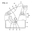
- the lever 60 is displaced (rotated or pivoted) to the connection position CP as shown in FIG. 4
- the operating portion 61 particularly comes into contact with the rear end part of the wire cover 22 to be locked and the pin main body/bodies 45 reach(es) the back end(s) of the cam groove(s) 63 and stop(s).
- the longer-side direction of the pin main body/bodies 45 particularly substantially is aligned in the extending direction ED of the cam grooves 63
- the shorter-side direction thereof particularly substantially is aligned with the groove width direction of the cam grooves 63 and/or the outer surface(s) of the pin main body/bodies 45 at the (both) end(s) in the shorter-side direction slide in contact or held in contact with the groove surface(s) of the cam groove(s) 63 as when the lever 60 is located at the initial position IP.
- the pin main body/bodies 45 that is/are part(s) of the cam pin(s) 43 to be inserted into the cam groove(s) 63 is/are formed to substantially be long in the extending direction ED of the cam groove(s) 63 and short in the groove width direction (direction perpendicular to the extending direction ED of the cam groove(s) 63).
- the strength of the cam pin(s) 43 is ensured to be high by thickening the part(s) long in the extending direction ED of the cam groove(s) 63 and an increase in the width of the cam groove(s) 63 is prevented by inserting the part(s) short in the groove width direction of the cam groove(s) 63 into the cam groove(s) 63.
- the strength of the cam pin(s) 43 can be increased without enlarging the connector.
- the pin main body/bodies 45 particularly substantially is/are in the form of solid cylinder(s), the strength of the cam pin(s) 43 is further increased.
- the pin main body/bodies 45 particularly has/have the oval outer shape long in the extending direction ED of the cam grooves 63, the curved surfaces of the cam pins 43 and the cam grooves 63 slide along each other, wherefore sliding stability is excellent.
- one or more cam pins of a second connector housing 40 are at least partly inserted into one or more respective cam grooves 63 of a lever 60 and, in that state, the lever 60 is displaced (particularly rotated or pivoted), whereby the cam pin(s) slide(s) along groove surface(s) of the cam groove(s) 63 to effect cam action and an operation of first and second connector housings 20, 40 proceeds.
- Part(s) of the cam pin(s) to be inserted into the cam groove(s) 63 is/are long in an extending direction ED of the cam groove(s) 63 and short in a groove width direction perpendicular to the extending direction ED of the cam groove(s) 63.
- FIG. 5 shows a second particular embodiment of the present invention.
- a projecting piece 46A of a cam pin 43A differs from the first embodiment.
- the other configuration is similar or substantially the same as in the first embodiment and not repeatedly described.
- the projecting piece 46A projects from the projecting end of a pin main body 45 over at least part of the circumference, particularly over the entire circumference.
- the projecting piece 46A particularly has an elliptical outer shape concentric with the pin main body 45.
- FIG. 6 shows a third particular embodiment of the present invention.
- a pin main body 45B of a cam pin 43B differs from the first embodiment.
- the other configuration is similar or substantially the same as in the first embodiment and not repeatedly described.
- the pin main body 45B has an angular circular outer shape which particularly substantially has an oval cross-section, although not an elliptical cross-section, and is long in a width direction and short in forward and backward directions.
- the outer peripheral surface of the pin main body 45B particularly includes a pair of facing sides 47 substantially parallel to each other along the width direction.
- FIG. 7 shows a fourth particular embodiment of the present invention.
- a pin main body 45C of a cam pin 43C differs from the first embodiment.
- the other configuration is similar or substantially the same as in the first embodiment and not repeatedly described.
- the pin main body 45C is formed with a hollowed portion 44 hollowed particularly over the substantially entire height.
- the hollowed portion 44 substantially extends in forward and backward directions in a widthwise central part of the pin main body 45C and has open front and rear ends.
- FIG. 8 shows a fifth particular embodiment of the present invention.
- a pin main body 45D of a cam pin 43D differs from the first embodiment.
- the other configuration is similar or substantially the same as in the first embodiment and not repeatedly described.
- the pin main body 45D is formed with hollowed portions 44D hollowed over the entire height. These hollowed portions 44D are paired at opposite sides of a widthwise central part of the pin main body 45D and each in the form of an opening having a semi-circular cross-section.
- FIG. 9 shows a sixth particular embodiment of the present invention.
- a pin main body 45E of a cam pin 43E differs from the first embodiment.
- the other configuration is similar or substantially the same as in the first embodiment and not repeatedly described.
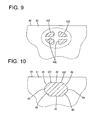
- the pin main body 45E is formed with one or more hollowed portions 44E particularly hollowed over the substantially entire height.
- the hollowed portions 44E particularly are paired at substantially opposite sides of a widthwise central part of the pin main body 45E and/or at substantially opposite sides of a central part thereof in forward and backward directions and/or particularly each in the form of an opening having a quarter-circular cross-section.
- FIG. 10 shows a seventh particular embodiment of the present invention.
- a pin main body 45F of a cam pin 43F differs from the first embodiment.
- the other configuration is similar or substantially the same as in the first embodiment and not repeatedly described.
- the pin main body 45F particularly has a polygonal cross-section, specifically an octagonal cross-section and/or has substantially the same diameter over the entire height.
- the pin main body 45F is defined by first facing sides 42 substantially parallel to each other along the width direction, second facing sides 48 substantially parallel to each other along forward and backward directions and four oblique sides 49 connecting both front and rear ends of the second facing sides 48 and both widthwise ends of the first facing sides 42 and extending obliquely straight.
- the first facing sides 42 are longer than the second facing sides 48 and the pin main body 45F is long in the width direction as a whole. Since the pin main body 45F has the polygonal outer shape according to the seventh embodiment, the strength of the cam pin 43F is further increased by thickened angular parts.
Landscapes
- Details Of Connecting Devices For Male And Female Coupling (AREA)
Abstract
Description
- The present invention relates to a lever-type connector and to a method of assembling it.
- A conventional lever-type connector is disclosed in
Japanese Unexamined Patent Publication No. 2008-130244 - In the process of connecting the two connector housings, the both divided cam pins are united with each other, thereby forming a cylindrical cam pin, and this cam pin slides along a groove surface of the cam groove to effect cam action as the lever is rotated, whereby a connecting operation of the two connector housings proceeds.
- In a multi-pole connector as described above, a large load is applied to a cam pin from a lever in a connection process since a multitude of terminal fittings have to be connected at a time. Thus, it is required to increase the strength of the cam pin. However, if the diameter of the cam pin is simply increased on the whole, the width of a cam groove for receiving this cam pin is also increased. This leads to the enlargement of the lever and consequently the enlargement of the connector.
- The present invention was completed in view of the above situation and an object thereof is to increase the strength of a cam pin without enlarging a connector.
- This object is solved according to the invention by the features of the independent claims. Particular embodiments of the invention are subject of the dependent claims.
- According to the invention, there is provided a lever-type connector, comprising a lever which is formed with an extending cam groove; a first connector housing on which the lever is displaceably or movably (particularly rotatably or pivotably) supported; and a second connector housing which is connectable to the first connector housing and from which a cam pin projects; the cam pin being inserted into the cam groove and, in that state, the lever being displaced or moved (particularly rotated or pivoted), whereby the cam pin substantially slides along a groove surface of the cam groove to effect cam action and an operation of connecting the first and second connector housings proceeds, wherein a part of the cam pin to be inserted into the cam groove is long in an extending direction of the cam groove and short in a groove width direction perpendicular to the extending direction of the cam groove.
- Since the part of the cam pin to be inserted into the cam groove is long in the extending direction of the cam groove and short in the groove width direction perpendicular to the extending direction of the cam groove, the strength of the cam pin is ensured to be high by thickening parts long in the extending direction of the cam groove and an increase in the width of the cam groove is prevented by inserting the parts short in the groove width direction of the cam groove into the cam groove. Thus, the strength of the cam pin can be increased without enlarging the connector.
- According to a particular embodiment, the part of the cam pin to be inserted into the cam groove is in the form of a solid cylinder.
- Since the part of the cam pin to be inserted into the cam groove is in the form of a solid cylinder, the strength of the cam pin is further increased.
- Particularly, the part of the cam pin to be inserted into the cam groove is formed with at least one hollowed portion.
- Since the part of the cam pin to be inserted into the cam groove is formed with the hollowed portion, formation of sinks can be prevented and shape accuracy of the cam pin can be improved.
- Further particularly, the part of the cam pin to be inserted into the cam groove has an oval outer shape long in the extending direction of the cam groove.
- Since the part of the cam pin to be inserted into the cam groove has the oval outer shape long in the extending direction of the cam groove, curved surfaces of the cam pin and the cam groove slide along each other, wherefore sliding stability is excellent.
- Further particularly, the part of the cam pin to be inserted into the cam groove has a polygonal outer shape long in the extending direction of the cam groove.
- Since the part of the cam pin to be inserted into the cam groove has the polygonal outer shape long in the extending direction of the cam groove, the strength of the cam pin is further increased by thickened angular parts.
- Further particularly, the cam pin comprises at least one projecting piece projecting radially outwardly from a projecting end of the part of the cam pin to be inserted into the cam groove.
- Further particularly, a dimension of the part of the cam pin to be inserted into the cam groove in a shorter side direction corresponds to the width of the cam groove.
- Further particularly, the part of the cam pin to be inserted into the cam groove is formed to have substantially the same configuration over the entire height.
- According to another aspect of the invention, there is further provided a method of assembling a lever-type connector, in particular according the above aspect of the invention or a particular embodiment thereof, comprising the following steps: displaceably or movably mounting a lever formed with at least one extending cam groove on a first connector housing; and connecting a second connector housing from which at least one cam pin projects to the first connector housing such that the cam pin is at least partly inserted into the cam groove and, in that state, displacing the lever, whereby the cam pin slides along a groove surface of the cam groove to effect cam action and an operation of connecting the first and second connector housings proceeds, wherein a part of the cam pin inserted into the cam groove is configured such as to be long in an extending direction of the cam groove and short in a groove width direction perpendicular to the extending direction of the cam groove.
- These and other objects, features and advantages of the present invention will become more apparent upon reading of the following detailed description of preferred embodiments and accompanying drawings. It should be understood that even though embodiments are separately described, single features thereof may be combined to additional embodiments.
-
FIG. 1 is a plan view of a lever-type connector according to a first embodiment of the present invention before connection, -
FIG. 2 is a plan view of the lever-type connector when the connection is started, -
FIG. 3 is a plan view of the lever-type connector during the connection, -
FIG. 4 is a plan view of the lever-type connector when the connection is completed, -
FIG. 5 is an enlarged plan view showing a cam pin in a lever-type connector according to a second embodiment, -
FIG. 6 is an enlarged section of a pin main body of a cam pin in a lever-type connector according to a third embodiment, -
FIG. 7 is an enlarged section of a pin main body of a cam pin in a lever-type connector according to a fourth embodiment, -
FIG. 8 is an enlarged section of a pin main body of a cam pin in a lever-type connector according to a fifth embodiment, -
FIG. 9 is an enlarged section of a pin main body of a cam pin in a lever-type connector according to a sixth embodiment, and -
FIG. 10 is an enlarged section of a pin main body of a cam pin in a lever-type connector according to a seventh embodiment. - A first particular embodiment of the present invention is described with reference to
FIGS. 1 to 4 . A lever-type connector 10 according to this embodiment includes first andsecond connector housings lever 60 to be displaceably (particularly rotatably or pivotably) mounted on thefirst connector housing 20. - The
first connector housing 20 is made e.g. of synthetic resin and, as shown inFIG. 1 , includes a housing main body 21 (particularly substantially in the form of a rectangular block long in a width direction) and a (particularly substantially cap-shaped)wire cover 22 to be mounted on (particularly a rear end part of) the housingmain body 21. One or more, particularly a plurality of unillustrated female terminal fittings are to be at least partly accommodated in the housingmain body 21 and connected to one or more respective end portions of unillustrated wires. Each wire is to be pulled out from the rear surface of the housingmain body 21, at least partly accommodated in a bent state in thewire cover 22 and drawn out to the outside through an opening at one widthwise side of thewire cover 22. One or more, particularly a pair of supportingshafts 23 are formed to project from one or more widthwise intermediate parts of one or more side surfaces of the housingmain body 21, particularly from substantially widthwise central parts of both side surfaces of the housingmain body 21. The (both) supporting shaft(s) 23 particularly has/have a substantially cylindrical shape and form rotary shafts for thelever 60. - The lever 60 (as a particular movable member) is made e.g. of synthetic resin and/or particularly substantially gate-shaped and includes an
operating portion 61 and one or more, particularly a pair ofarm portions 62 particularly projecting substantially in parallel from both ends of theoperating portion 61. Thelever 60 particularly is to be mounted from behind to straddle thefirst connector housing 20 and the botharm portions 62 are arranged at the outer sides of the both side surfaces of the housingmain body 21 when thelever 60 is mounted. One or more, particularly a pair ofcam grooves 63 extending in a curved manner in a specified (predetermined or predeterminable) direction ED and one or more (particularly substantially circular) bearingholes 64 are formed to penetrate through the (both) arm portion(s) 62. The supporting shaft(s) 23 is/are to be at least partly fitted and inserted into the bearing hole(s) 64 of the (particularly both) arm portion(s) 62. Such alever 60 is displaceable (particularly rotatable or pivotable) about the supporting shaft(s) 23 between an initial position IP where theoperating portion 61 particularly is located on the other widthwise side of thefirst connector housing 20 and a connection position CP where theoperating portion 61 particularly is located at one widthwise side of thefirst connector housing 20. Note that the (both) arm portion(s) 62 is/are (each) formed with an introducinggroove 65 communicating with the entrance of thecam groove 63, and the introducing groove(s) 65 is/are arranged to substantially face forward at the initial position IP. - The
second connector housing 40 is made e.g. of synthetic resin and, as shown inFIG. 1 , includes areceptacle 41 particularly substantially in the form of a rectangular tube long in the width direction. One or more, particularly a plurality of unillustrated male terminal fittings are arranged to project into thereceptacle 41. The (particularly each) male terminal fitting is to be electrically conductively connected to the corresponding female terminal fitting as the first andsecond connector housings - One or more, particularly a pair of
cam pins 43 engageable with the one or morerespective cam grooves 63 by being inserted thereinto are formed to project in a widthwise intermediate part (particularly substantially in a widthwise central part) of thereceptacle 41. As shown inFIG. 1 , thecam pin 43 is composed of or comprises a solid and substantially cylindrical pinmain body 45 and one or more, particularly a pair of projectingpieces 46 projecting radially outwardly from (particularly substantially opposite radial ends of) the projecting end of the pinmain body 45. Specifically, the pinmain body 45 substantially has an oval cross-section, specifically an elliptical cross-section and/or is formed to have substantially the same diameter over the entire height. Specifically, the pinmain body 45 has an elliptical outer shape long in the width direction (direction perpendicular to the connecting direction CD) and short in forward and backward directions (directions along the connecting direction CD). A dimension of the pinmain body 45 in a shorter side direction corresponds to the width of thecam groove 63. Further, the (particularly both) projecting piece(s) 46 particularly is/are in the form of rectangular plate(s) and/or project(s) from the (particularly both) end(s) of the pinmain body 45 in the shorter-side direction. The (both) projectingpieces 46 can slide along front and rear groove edge part(s) of thecam groove 63 on the outer side surface of (each of) the both arm portion(s) 63 in the process of displacing (rotating) thelever 60. - The lever-
type connector 10 according to this embodiment is structured as described above. Next, an operation of connecting the first andsecond connector housings - First, the
lever 60 is held or positioned at the initial position IP and, in that state, the housingmain body 21 of thefirst connector housing 20 is at least partly inserted into thereceptacle 41 of thesecond connector housing 40 as shown inFIG. 2 . Then, the pin main body/bodies 45 of the cam pin(s) 43 is/are introduced into the introducing groove(s) 65 and further inserted into the entrance(s) of the cam groove(s) 63. At this time, the pin main body/bodies 45 particularly is/are arranged such that a longer-side direction thereof substantially is aligned with an extending direction ED of thecam grooves 63 and/or the shorter-side direction thereof particularly substantially is aligned with a direction perpendicular to the extending direction ED of thecam grooves 63, i.e. a groove width direction. - Subsequently, as shown in
FIGS. 2 and3 , thelever 60 is displaced (particularly rotated or pivoted) toward the connection position CP particularly by holding the operatingportion 61. Then, the outer peripheral surface(s) of the pin main body/bodies 45, specifically, the outer surface(s) at the (both) end(s) of the outer peripheral surface(s) of the pin main body/bodies 45 in the shorter-side direction slide along the groove surface(s) of the cam groove(s) 63 and cam action works between thelever 60 and thesecond connector housing 40. By this, the housingmain body 21 is fitted into thereceptacle 41 with a small connecting force or its insertion is assisted. As the connecting operation further proceeds and thelever 60 is displaced (rotated or pivoted) to the connection position CP as shown inFIG. 4 , the operatingportion 61 particularly comes into contact with the rear end part of thewire cover 22 to be locked and the pin main body/bodies 45 reach(es) the back end(s) of the cam groove(s) 63 and stop(s). Note that, while thelever 60 is moving from the initial position IP to the connection position CP during the connecting operation and when thelever 60 reaches the connection position CP, the longer-side direction of the pin main body/bodies 45 particularly substantially is aligned in the extending direction ED of thecam grooves 63, the shorter-side direction thereof particularly substantially is aligned with the groove width direction of thecam grooves 63 and/or the outer surface(s) of the pin main body/bodies 45 at the (both) end(s) in the shorter-side direction slide in contact or held in contact with the groove surface(s) of the cam groove(s) 63 as when thelever 60 is located at the initial position IP. - As described above, according to this embodiment, the pin main body/
bodies 45 that is/are part(s) of the cam pin(s) 43 to be inserted into the cam groove(s) 63 is/are formed to substantially be long in the extending direction ED of the cam groove(s) 63 and short in the groove width direction (direction perpendicular to the extending direction ED of the cam groove(s) 63). Thus, the strength of the cam pin(s) 43 is ensured to be high by thickening the part(s) long in the extending direction ED of the cam groove(s) 63 and an increase in the width of the cam groove(s) 63 is prevented by inserting the part(s) short in the groove width direction of the cam groove(s) 63 into the cam groove(s) 63. Thus, according to this embodiment, the strength of the cam pin(s) 43 can be increased without enlarging the connector. Further, since the pin main body/bodies 45 particularly substantially is/are in the form of solid cylinder(s), the strength of the cam pin(s) 43 is further increased. - Further, since the pin main body/
bodies 45 particularly has/have the oval outer shape long in the extending direction ED of thecam grooves 63, the curved surfaces of the cam pins 43 and thecam grooves 63 slide along each other, wherefore sliding stability is excellent. - Accordingly, to increase the strength of a cam pin without enlarging a connector, one or more cam pins of a
second connector housing 40 are at least partly inserted into one or morerespective cam grooves 63 of alever 60 and, in that state, thelever 60 is displaced (particularly rotated or pivoted), whereby the cam pin(s) slide(s) along groove surface(s) of the cam groove(s) 63 to effect cam action and an operation of first andsecond connector housings -
FIG. 5 shows a second particular embodiment of the present invention. In the second embodiment, a projectingpiece 46A of acam pin 43A differs from the first embodiment. The other configuration is similar or substantially the same as in the first embodiment and not repeatedly described. The projectingpiece 46A projects from the projecting end of a pinmain body 45 over at least part of the circumference, particularly over the entire circumference. The projectingpiece 46A particularly has an elliptical outer shape concentric with the pinmain body 45. -
FIG. 6 shows a third particular embodiment of the present invention. In the third embodiment, a pinmain body 45B of acam pin 43B differs from the first embodiment. The other configuration is similar or substantially the same as in the first embodiment and not repeatedly described. The pinmain body 45B has an angular circular outer shape which particularly substantially has an oval cross-section, although not an elliptical cross-section, and is long in a width direction and short in forward and backward directions. The outer peripheral surface of the pinmain body 45B particularly includes a pair of facingsides 47 substantially parallel to each other along the width direction. -
FIG. 7 shows a fourth particular embodiment of the present invention. In the fourth embodiment, a pinmain body 45C of acam pin 43C differs from the first embodiment. The other configuration is similar or substantially the same as in the first embodiment and not repeatedly described. The pinmain body 45C is formed with a hollowedportion 44 hollowed particularly over the substantially entire height. The hollowedportion 44 substantially extends in forward and backward directions in a widthwise central part of the pinmain body 45C and has open front and rear ends. By forming the hollowedportion 44, formation of sinks can be prevented and shape accuracy of thecam pin 43C can be improved. -
FIG. 8 shows a fifth particular embodiment of the present invention. In the fifth embodiment, a pinmain body 45D of acam pin 43D differs from the first embodiment. The other configuration is similar or substantially the same as in the first embodiment and not repeatedly described. Similarly to the fourth embodiment, the pinmain body 45D is formed with hollowedportions 44D hollowed over the entire height. Thesehollowed portions 44D are paired at opposite sides of a widthwise central part of the pinmain body 45D and each in the form of an opening having a semi-circular cross-section. -
FIG. 9 shows a sixth particular embodiment of the present invention. In the sixth embodiment, a pinmain body 45E of acam pin 43E differs from the first embodiment. The other configuration is similar or substantially the same as in the first embodiment and not repeatedly described. Similarly to the fourth and fifth embodiments, the pinmain body 45E is formed with one or morehollowed portions 44E particularly hollowed over the substantially entire height. Thehollowed portions 44E particularly are paired at substantially opposite sides of a widthwise central part of the pinmain body 45E and/or at substantially opposite sides of a central part thereof in forward and backward directions and/or particularly each in the form of an opening having a quarter-circular cross-section. -
FIG. 10 shows a seventh particular embodiment of the present invention. In the seventh embodiment, a pinmain body 45F of acam pin 43F differs from the first embodiment. The other configuration is similar or substantially the same as in the first embodiment and not repeatedly described. The pinmain body 45F particularly has a polygonal cross-section, specifically an octagonal cross-section and/or has substantially the same diameter over the entire height. Specifically, the pinmain body 45F is defined by first facingsides 42 substantially parallel to each other along the width direction, second facing sides 48 substantially parallel to each other along forward and backward directions and fouroblique sides 49 connecting both front and rear ends of the second facing sides 48 and both widthwise ends of the first facingsides 42 and extending obliquely straight. The first facing sides 42 are longer than the second facing sides 48 and the pinmain body 45F is long in the width direction as a whole. Since the pinmain body 45F has the polygonal outer shape according to the seventh embodiment, the strength of thecam pin 43F is further increased by thickened angular parts. - The present invention is not limited to the above described and illustrated embodiments. For example, the following embodiments are also included in the technical scope of the present invention.
- (1) The projecting piece(s) may be omitted.
- (2) The pin main body of the seventh embodiment may have a polygonal cross-section other than the octagonal cross-section.
- (3) A pin main body having a polygonal cross-section as in the seventh embodiment may be formed with hollowed portion(s).
- (4) The lever may be formed of a single plate which is flat as a whole.
-
- 10 ... lever-type connector
- 20 ... first connector housing
- 21 ... housing main body
- 40 ... second connector housing
- 41 ... receptacle
- 43, 43A, 43B, 43C, 43D, 43E, 43F ... cam pin
- 44, 44D, 44E ... hollowed portion
- 45, 45B, 45C, 45D, 45E, 45F ... pin main body (part of cam pin to be inserted into cam groove)
- 46 ... projecting piece
- 60 ... lever
- 62 ... arm portion
- 63 ... cam groove
Claims (9)
- A lever-type connector (10), comprising:a lever (60) which is formed with at least one extending cam groove (63);a first connector housing (20) on or in which the lever (60) is displaceably supported; anda second connector housing (40) which is connectable to the first connector housing (20) and from which at least one cam pin (43; 43A; 43B; 43C; 43D; 43E; 43F) projects;the cam pin (43; 43A; 43B; 43C; 43D; 43E; 43F) being at least partly inserted into the cam groove (63) and, in that state, the lever (60) being displaced, whereby the cam pin (43; 43A; 43B; 43C; 43D; 43E; 43F) slides along a groove surface of the cam groove (63) to effect cam action and an operation of connecting the first and second connector housings (20, 40) proceeds,wherein a part (45; 45B; 45C; 45D; 45E; 45F) of the cam pin (43; 43A; 43B; 43C; 43D; 43E; 43F) to be inserted into the cam groove (63) is long in an extending direction (ED) of the cam groove (63) and short in a groove width direction perpendicular to the extending direction (ED) of the cam groove (63).
- A lever-type connector according to claim 1, wherein the part (45) of the cam pin (43) to be inserted into the cam groove (63) is in the form of a solid cylinder.
- A lever-type connector according to claim 1, wherein the part (45C; 45D; 45E) of the cam pin (43C; 43D; 43E) to be inserted into the cam groove (63) is formed with at least one hollowed portion.
- A lever-type connector according to any one of the preceding claims, wherein the part (45; 45B; 45C; 45D; 45E) of the cam pin (43; 43A; 43B; 43C; 43D; 43E) to be inserted into the cam groove (63) has an oval outer shape long in the extending direction (ED) of the cam groove (63).
- A lever-type connector according to any one of claims 1 to 3, wherein the part (45F) of the cam pin (43F) to be inserted into the cam groove (63) has a polygonal outer shape long in the extending direction (ED) of the cam groove (63).
- A lever-type connector according to any one of the preceding claims, wherein the cam pin (43) comprises at least one projecting piece (46) projecting radially outwardly from a projecting end of the part (45; 45B; 45C; 45D; 45E; 45F) of the cam pin (43; 43A; 43B; 43C; 43D; 43E; 43F) to be inserted into the cam groove (63).
- A lever-type connector according to any one of the preceding claims, wherein a dimension of the part (45; 45B; 45C; 45D; 45E; 45F) of the cam pin (43; 43A; 43B; 43C; 43D; 43E; 43F) to be inserted into the cam groove (63) in a shorter side direction corresponds to the width of the cam groove (63).
- A lever-type connector according to any one of the preceding claims, wherein the part (45; 45B; 45C; 45D; 45E; 45F) of the cam pin (43; 43A; 43B; 43C; 43D; 43E; 43F) to be inserted into the cam groove (63) is formed to have substantially the same configuration over the entire height.
- A method of assembling a lever-type connector (10), comprising the following steps:displaceably mounting a lever (60) formed with at least one extending cam groove (63) on a first connector housing (20); andconnecting a second connector housing (40) from which at least one cam pin (43; 43A; 43B; 43C; 43D; 43E; 43F) projects to the first connector housing (20) such that the cam pin (43; 43A; 43B; 43C; 43D; 43E; 43F) is at least partly inserted into the cam groove (63) and, in that state, displacing the lever (60), whereby the cam pin (43; 43A; 43B; 43C; 43D; 43E; 43F) slides along a groove surface of the cam groove (63) to effect cam action and an operation of connecting the first and second connector housings (20, 40) proceeds,wherein a part (45; 45B; 45C; 45D; 45E; 45F) of the cam pin (43; 43A; 43B; 43C; 43D; 43E; 43F) inserted into the cam groove (63) is configured such as to be long in an extending direction (ED) of the cam groove (63) and short in a groove width direction perpendicular to the extending direction (ED) of the cam groove (63).
Applications Claiming Priority (1)
| Application Number | Priority Date | Filing Date | Title |
|---|---|---|---|
| JP2011174384A JP5686069B2 (en) | 2011-08-09 | 2011-08-09 | Lever type connector |
Publications (2)
| Publication Number | Publication Date |
|---|---|
| EP2557638A1 true EP2557638A1 (en) | 2013-02-13 |
| EP2557638B1 EP2557638B1 (en) | 2018-04-18 |
Family
ID=46578800
Family Applications (1)
| Application Number | Title | Priority Date | Filing Date |
|---|---|---|---|
| EP12005124.8A Not-in-force EP2557638B1 (en) | 2011-08-09 | 2012-07-11 | Lever-type connector and method of assembling it |
Country Status (2)
| Country | Link |
|---|---|
| EP (1) | EP2557638B1 (en) |
| JP (1) | JP5686069B2 (en) |
Cited By (1)
| Publication number | Priority date | Publication date | Assignee | Title |
|---|---|---|---|---|
| DE202014105827U1 (en) | 2013-12-06 | 2015-01-22 | Tyco Electronics (Shanghai) Co., Ltd. | Connector housing, connector and connector assembly |
Citations (5)
| Publication number | Priority date | Publication date | Assignee | Title |
|---|---|---|---|---|
| JPH1167338A (en) * | 1997-08-27 | 1999-03-09 | Sumitomo Wiring Syst Ltd | Lever-type connector |
| JP2003178837A (en) * | 2001-12-07 | 2003-06-27 | Sumitomo Wiring Syst Ltd | Lever type connector |
| JP2008130244A (en) | 2006-11-16 | 2008-06-05 | Sumitomo Wiring Syst Ltd | Connector |
| EP2075880A1 (en) * | 2007-12-28 | 2009-07-01 | Sumitomo Wiring Systems, Ltd. | Lever-type connector, connector assembly and connecting method |
| EP2075879A1 (en) * | 2007-12-25 | 2009-07-01 | Sumitomo Wiring Systems, Ltd. | A connector and a connecting method |
Family Cites Families (5)
| Publication number | Priority date | Publication date | Assignee | Title |
|---|---|---|---|---|
| JP3573280B2 (en) * | 2001-06-26 | 2004-10-06 | 住友電装株式会社 | Lever type connector |
| JP2003100385A (en) * | 2001-09-25 | 2003-04-04 | Yazaki Corp | Lever fitting type power supply circuit breaker |
| JP2006196225A (en) * | 2005-01-11 | 2006-07-27 | Sumitomo Wiring Syst Ltd | Connector |
| JP2009093930A (en) * | 2007-10-10 | 2009-04-30 | Sumitomo Wiring Syst Ltd | Lever type connector |
| JP5217994B2 (en) * | 2008-12-10 | 2013-06-19 | 住友電装株式会社 | Lever type connector |
-
2011
- 2011-08-09 JP JP2011174384A patent/JP5686069B2/en not_active Expired - Fee Related
-
2012
- 2012-07-11 EP EP12005124.8A patent/EP2557638B1/en not_active Not-in-force
Patent Citations (5)
| Publication number | Priority date | Publication date | Assignee | Title |
|---|---|---|---|---|
| JPH1167338A (en) * | 1997-08-27 | 1999-03-09 | Sumitomo Wiring Syst Ltd | Lever-type connector |
| JP2003178837A (en) * | 2001-12-07 | 2003-06-27 | Sumitomo Wiring Syst Ltd | Lever type connector |
| JP2008130244A (en) | 2006-11-16 | 2008-06-05 | Sumitomo Wiring Syst Ltd | Connector |
| EP2075879A1 (en) * | 2007-12-25 | 2009-07-01 | Sumitomo Wiring Systems, Ltd. | A connector and a connecting method |
| EP2075880A1 (en) * | 2007-12-28 | 2009-07-01 | Sumitomo Wiring Systems, Ltd. | Lever-type connector, connector assembly and connecting method |
Cited By (1)
| Publication number | Priority date | Publication date | Assignee | Title |
|---|---|---|---|---|
| DE202014105827U1 (en) | 2013-12-06 | 2015-01-22 | Tyco Electronics (Shanghai) Co., Ltd. | Connector housing, connector and connector assembly |
Also Published As
| Publication number | Publication date |
|---|---|
| JP2013037957A (en) | 2013-02-21 |
| JP5686069B2 (en) | 2015-03-18 |
| EP2557638B1 (en) | 2018-04-18 |
Similar Documents
| Publication | Publication Date | Title |
|---|---|---|
| EP2276121B1 (en) | Lever type connector | |
| US9231348B2 (en) | Waterproof connector | |
| US7329133B2 (en) | Connector | |
| EP2706621A1 (en) | Connector, connector assembly and assembly method | |
| US7497721B2 (en) | Tool extractable contacts for electrical connectors | |
| EP2456020A1 (en) | Lever-type connector | |
| EP2523262B1 (en) | Seal cover for in-vehicle electric device and production method therefor | |
| CN101257167B (en) | Connector and a connector assembly | |
| EP2346120A1 (en) | Shield connector and production method thereof | |
| JP5945964B2 (en) | connector | |
| US20150318639A1 (en) | Lever-type connector | |
| US20110151694A1 (en) | Lever-type connector | |
| EP2894722B1 (en) | Terminal | |
| US20090149046A1 (en) | Connector | |
| US10483692B2 (en) | Levery-type connector | |
| JP2014165027A (en) | Connector with booster mechanism | |
| US9923305B2 (en) | Connector | |
| JP2019153401A (en) | Connection terminal | |
| US10044138B2 (en) | Connector with linearly movable operating member that is movable optionally in opposite first and second moving directions for connecting the connector to a mating connector | |
| US9122299B2 (en) | Disconnect lever and method of manufacture | |
| EP2557638A1 (en) | Level-type connector and method of assembling it | |
| WO2014126123A1 (en) | Female terminal and terminal manufacturing device | |
| JP6587595B2 (en) | Lever type connector | |
| US7661970B2 (en) | Connector | |
| US9899768B2 (en) | Connector with operating member to assist connection to mating connector and resilient piece to restrict inadvertent displacement of operating member |
Legal Events
| Date | Code | Title | Description |
|---|---|---|---|
| PUAI | Public reference made under article 153(3) epc to a published international application that has entered the european phase |
Free format text: ORIGINAL CODE: 0009012 |
|
| AK | Designated contracting states |
Kind code of ref document: A1 Designated state(s): AL AT BE BG CH CY CZ DE DK EE ES FI FR GB GR HR HU IE IS IT LI LT LU LV MC MK MT NL NO PL PT RO RS SE SI SK SM TR |
|
| AX | Request for extension of the european patent |
Extension state: BA ME |
|
| 17P | Request for examination filed |
Effective date: 20130801 |
|
| RBV | Designated contracting states (corrected) |
Designated state(s): AL AT BE BG CH CY CZ DE DK EE ES FI FR GB GR HR HU IE IS IT LI LT LU LV MC MK MT NL NO PL PT RO RS SE SI SK SM TR |
|
| 17Q | First examination report despatched |
Effective date: 20141217 |
|
| GRAP | Despatch of communication of intention to grant a patent |
Free format text: ORIGINAL CODE: EPIDOSNIGR1 |
|
| INTG | Intention to grant announced |
Effective date: 20170613 |
|
| GRAJ | Information related to disapproval of communication of intention to grant by the applicant or resumption of examination proceedings by the epo deleted |
Free format text: ORIGINAL CODE: EPIDOSDIGR1 |
|
| INTC | Intention to grant announced (deleted) | ||
| GRAP | Despatch of communication of intention to grant a patent |
Free format text: ORIGINAL CODE: EPIDOSNIGR1 |
|
| INTG | Intention to grant announced |
Effective date: 20171206 |
|
| GRAS | Grant fee paid |
Free format text: ORIGINAL CODE: EPIDOSNIGR3 |
|
| GRAA | (expected) grant |
Free format text: ORIGINAL CODE: 0009210 |
|
| AK | Designated contracting states |
Kind code of ref document: B1 Designated state(s): AL AT BE BG CH CY CZ DE DK EE ES FI FR GB GR HR HU IE IS IT LI LT LU LV MC MK MT NL NO PL PT RO RS SE SI SK SM TR |
|
| REG | Reference to a national code |
Ref country code: GB Ref legal event code: FG4D |
|
| REG | Reference to a national code |
Ref country code: CH Ref legal event code: EP |
|
| REG | Reference to a national code |
Ref country code: AT Ref legal event code: REF Ref document number: 991422 Country of ref document: AT Kind code of ref document: T Effective date: 20180515 |
|
| REG | Reference to a national code |
Ref country code: IE Ref legal event code: FG4D |
|
| REG | Reference to a national code |
Ref country code: DE Ref legal event code: R096 Ref document number: 602012045233 Country of ref document: DE |
|
| REG | Reference to a national code |
Ref country code: NL Ref legal event code: MP Effective date: 20180418 |
|
| REG | Reference to a national code |
Ref country code: LT Ref legal event code: MG4D |
|
| PG25 | Lapsed in a contracting state [announced via postgrant information from national office to epo] |
Ref country code: NL Free format text: LAPSE BECAUSE OF FAILURE TO SUBMIT A TRANSLATION OF THE DESCRIPTION OR TO PAY THE FEE WITHIN THE PRESCRIBED TIME-LIMIT Effective date: 20180418 |
|
| PG25 | Lapsed in a contracting state [announced via postgrant information from national office to epo] |
Ref country code: AL Free format text: LAPSE BECAUSE OF FAILURE TO SUBMIT A TRANSLATION OF THE DESCRIPTION OR TO PAY THE FEE WITHIN THE PRESCRIBED TIME-LIMIT Effective date: 20180418 Ref country code: SE Free format text: LAPSE BECAUSE OF FAILURE TO SUBMIT A TRANSLATION OF THE DESCRIPTION OR TO PAY THE FEE WITHIN THE PRESCRIBED TIME-LIMIT Effective date: 20180418 Ref country code: PL Free format text: LAPSE BECAUSE OF FAILURE TO SUBMIT A TRANSLATION OF THE DESCRIPTION OR TO PAY THE FEE WITHIN THE PRESCRIBED TIME-LIMIT Effective date: 20180418 Ref country code: LT Free format text: LAPSE BECAUSE OF FAILURE TO SUBMIT A TRANSLATION OF THE DESCRIPTION OR TO PAY THE FEE WITHIN THE PRESCRIBED TIME-LIMIT Effective date: 20180418 Ref country code: ES Free format text: LAPSE BECAUSE OF FAILURE TO SUBMIT A TRANSLATION OF THE DESCRIPTION OR TO PAY THE FEE WITHIN THE PRESCRIBED TIME-LIMIT Effective date: 20180418 Ref country code: BG Free format text: LAPSE BECAUSE OF FAILURE TO SUBMIT A TRANSLATION OF THE DESCRIPTION OR TO PAY THE FEE WITHIN THE PRESCRIBED TIME-LIMIT Effective date: 20180718 Ref country code: FI Free format text: LAPSE BECAUSE OF FAILURE TO SUBMIT A TRANSLATION OF THE DESCRIPTION OR TO PAY THE FEE WITHIN THE PRESCRIBED TIME-LIMIT Effective date: 20180418 Ref country code: NO Free format text: LAPSE BECAUSE OF FAILURE TO SUBMIT A TRANSLATION OF THE DESCRIPTION OR TO PAY THE FEE WITHIN THE PRESCRIBED TIME-LIMIT Effective date: 20180718 |
|
| PG25 | Lapsed in a contracting state [announced via postgrant information from national office to epo] |
Ref country code: GR Free format text: LAPSE BECAUSE OF FAILURE TO SUBMIT A TRANSLATION OF THE DESCRIPTION OR TO PAY THE FEE WITHIN THE PRESCRIBED TIME-LIMIT Effective date: 20180719 Ref country code: RS Free format text: LAPSE BECAUSE OF FAILURE TO SUBMIT A TRANSLATION OF THE DESCRIPTION OR TO PAY THE FEE WITHIN THE PRESCRIBED TIME-LIMIT Effective date: 20180418 Ref country code: LV Free format text: LAPSE BECAUSE OF FAILURE TO SUBMIT A TRANSLATION OF THE DESCRIPTION OR TO PAY THE FEE WITHIN THE PRESCRIBED TIME-LIMIT Effective date: 20180418 Ref country code: HR Free format text: LAPSE BECAUSE OF FAILURE TO SUBMIT A TRANSLATION OF THE DESCRIPTION OR TO PAY THE FEE WITHIN THE PRESCRIBED TIME-LIMIT Effective date: 20180418 |
|
| REG | Reference to a national code |
Ref country code: AT Ref legal event code: MK05 Ref document number: 991422 Country of ref document: AT Kind code of ref document: T Effective date: 20180418 |
|
| PG25 | Lapsed in a contracting state [announced via postgrant information from national office to epo] |
Ref country code: PT Free format text: LAPSE BECAUSE OF FAILURE TO SUBMIT A TRANSLATION OF THE DESCRIPTION OR TO PAY THE FEE WITHIN THE PRESCRIBED TIME-LIMIT Effective date: 20180820 |
|
| REG | Reference to a national code |
Ref country code: DE Ref legal event code: R097 Ref document number: 602012045233 Country of ref document: DE |
|
| PG25 | Lapsed in a contracting state [announced via postgrant information from national office to epo] |
Ref country code: SK Free format text: LAPSE BECAUSE OF FAILURE TO SUBMIT A TRANSLATION OF THE DESCRIPTION OR TO PAY THE FEE WITHIN THE PRESCRIBED TIME-LIMIT Effective date: 20180418 Ref country code: EE Free format text: LAPSE BECAUSE OF FAILURE TO SUBMIT A TRANSLATION OF THE DESCRIPTION OR TO PAY THE FEE WITHIN THE PRESCRIBED TIME-LIMIT Effective date: 20180418 Ref country code: DK Free format text: LAPSE BECAUSE OF FAILURE TO SUBMIT A TRANSLATION OF THE DESCRIPTION OR TO PAY THE FEE WITHIN THE PRESCRIBED TIME-LIMIT Effective date: 20180418 Ref country code: AT Free format text: LAPSE BECAUSE OF FAILURE TO SUBMIT A TRANSLATION OF THE DESCRIPTION OR TO PAY THE FEE WITHIN THE PRESCRIBED TIME-LIMIT Effective date: 20180418 Ref country code: CZ Free format text: LAPSE BECAUSE OF FAILURE TO SUBMIT A TRANSLATION OF THE DESCRIPTION OR TO PAY THE FEE WITHIN THE PRESCRIBED TIME-LIMIT Effective date: 20180418 Ref country code: RO Free format text: LAPSE BECAUSE OF FAILURE TO SUBMIT A TRANSLATION OF THE DESCRIPTION OR TO PAY THE FEE WITHIN THE PRESCRIBED TIME-LIMIT Effective date: 20180418 |
|
| PLBE | No opposition filed within time limit |
Free format text: ORIGINAL CODE: 0009261 |
|
| STAA | Information on the status of an ep patent application or granted ep patent |
Free format text: STATUS: NO OPPOSITION FILED WITHIN TIME LIMIT |
|
| PG25 | Lapsed in a contracting state [announced via postgrant information from national office to epo] |
Ref country code: IT Free format text: LAPSE BECAUSE OF FAILURE TO SUBMIT A TRANSLATION OF THE DESCRIPTION OR TO PAY THE FEE WITHIN THE PRESCRIBED TIME-LIMIT Effective date: 20180418 Ref country code: SM Free format text: LAPSE BECAUSE OF FAILURE TO SUBMIT A TRANSLATION OF THE DESCRIPTION OR TO PAY THE FEE WITHIN THE PRESCRIBED TIME-LIMIT Effective date: 20180418 |
|
| REG | Reference to a national code |
Ref country code: CH Ref legal event code: PL |
|
| 26N | No opposition filed |
Effective date: 20190121 |
|
| GBPC | Gb: european patent ceased through non-payment of renewal fee |
Effective date: 20180718 |
|
| PG25 | Lapsed in a contracting state [announced via postgrant information from national office to epo] |
Ref country code: MC Free format text: LAPSE BECAUSE OF FAILURE TO SUBMIT A TRANSLATION OF THE DESCRIPTION OR TO PAY THE FEE WITHIN THE PRESCRIBED TIME-LIMIT Effective date: 20180418 Ref country code: LU Free format text: LAPSE BECAUSE OF NON-PAYMENT OF DUE FEES Effective date: 20180711 |
|
| REG | Reference to a national code |
Ref country code: BE Ref legal event code: MM Effective date: 20180731 |
|
| REG | Reference to a national code |
Ref country code: IE Ref legal event code: MM4A |
|
| PG25 | Lapsed in a contracting state [announced via postgrant information from national office to epo] |
Ref country code: GB Free format text: LAPSE BECAUSE OF NON-PAYMENT OF DUE FEES Effective date: 20180718 Ref country code: LI Free format text: LAPSE BECAUSE OF NON-PAYMENT OF DUE FEES Effective date: 20180731 Ref country code: CH Free format text: LAPSE BECAUSE OF NON-PAYMENT OF DUE FEES Effective date: 20180731 Ref country code: IE Free format text: LAPSE BECAUSE OF NON-PAYMENT OF DUE FEES Effective date: 20180711 Ref country code: FR Free format text: LAPSE BECAUSE OF NON-PAYMENT OF DUE FEES Effective date: 20180731 |
|
| PG25 | Lapsed in a contracting state [announced via postgrant information from national office to epo] |
Ref country code: BE Free format text: LAPSE BECAUSE OF NON-PAYMENT OF DUE FEES Effective date: 20180731 Ref country code: SI Free format text: LAPSE BECAUSE OF FAILURE TO SUBMIT A TRANSLATION OF THE DESCRIPTION OR TO PAY THE FEE WITHIN THE PRESCRIBED TIME-LIMIT Effective date: 20180418 |
|
| PG25 | Lapsed in a contracting state [announced via postgrant information from national office to epo] |
Ref country code: MT Free format text: LAPSE BECAUSE OF NON-PAYMENT OF DUE FEES Effective date: 20180711 |
|
| PG25 | Lapsed in a contracting state [announced via postgrant information from national office to epo] |
Ref country code: TR Free format text: LAPSE BECAUSE OF FAILURE TO SUBMIT A TRANSLATION OF THE DESCRIPTION OR TO PAY THE FEE WITHIN THE PRESCRIBED TIME-LIMIT Effective date: 20180418 |
|
| PG25 | Lapsed in a contracting state [announced via postgrant information from national office to epo] |
Ref country code: HU Free format text: LAPSE BECAUSE OF FAILURE TO SUBMIT A TRANSLATION OF THE DESCRIPTION OR TO PAY THE FEE WITHIN THE PRESCRIBED TIME-LIMIT; INVALID AB INITIO Effective date: 20120711 |
|
| PG25 | Lapsed in a contracting state [announced via postgrant information from national office to epo] |
Ref country code: CY Free format text: LAPSE BECAUSE OF FAILURE TO SUBMIT A TRANSLATION OF THE DESCRIPTION OR TO PAY THE FEE WITHIN THE PRESCRIBED TIME-LIMIT Effective date: 20180418 Ref country code: MK Free format text: LAPSE BECAUSE OF NON-PAYMENT OF DUE FEES Effective date: 20180418 |
|
| PG25 | Lapsed in a contracting state [announced via postgrant information from national office to epo] |
Ref country code: IS Free format text: LAPSE BECAUSE OF FAILURE TO SUBMIT A TRANSLATION OF THE DESCRIPTION OR TO PAY THE FEE WITHIN THE PRESCRIBED TIME-LIMIT Effective date: 20180818 |
|
| PGFP | Annual fee paid to national office [announced via postgrant information from national office to epo] |
Ref country code: DE Payment date: 20200630 Year of fee payment: 9 |
|
| REG | Reference to a national code |
Ref country code: DE Ref legal event code: R119 Ref document number: 602012045233 Country of ref document: DE |
|
| PG25 | Lapsed in a contracting state [announced via postgrant information from national office to epo] |
Ref country code: DE Free format text: LAPSE BECAUSE OF NON-PAYMENT OF DUE FEES Effective date: 20220201 |