EP2276121B1 - Lever type connector - Google Patents
Lever type connector Download PDFInfo
- Publication number
- EP2276121B1 EP2276121B1 EP09724788.6A EP09724788A EP2276121B1 EP 2276121 B1 EP2276121 B1 EP 2276121B1 EP 09724788 A EP09724788 A EP 09724788A EP 2276121 B1 EP2276121 B1 EP 2276121B1
- Authority
- EP
- European Patent Office
- Prior art keywords
- lever
- housing
- wire cover
- side plates
- type connector
- Prior art date
- Legal status (The legal status is an assumption and is not a legal conclusion. Google has not performed a legal analysis and makes no representation as to the accuracy of the status listed.)
- Active
Links
Images


Classifications
-
- H—ELECTRICITY
- H01—ELECTRIC ELEMENTS
- H01R—ELECTRICALLY-CONDUCTIVE CONNECTIONS; STRUCTURAL ASSOCIATIONS OF A PLURALITY OF MUTUALLY-INSULATED ELECTRICAL CONNECTING ELEMENTS; COUPLING DEVICES; CURRENT COLLECTORS
- H01R13/00—Details of coupling devices of the kinds covered by groups H01R12/70 or H01R24/00 - H01R33/00
- H01R13/62—Means for facilitating engagement or disengagement of coupling parts or for holding them in engagement
- H01R13/629—Additional means for facilitating engagement or disengagement of coupling parts, e.g. aligning or guiding means, levers, gas pressure electrical locking indicators, manufacturing tolerances
- H01R13/62933—Comprising exclusively pivoting lever
- H01R13/62944—Pivoting lever comprising gear teeth
-
- H—ELECTRICITY
- H01—ELECTRIC ELEMENTS
- H01R—ELECTRICALLY-CONDUCTIVE CONNECTIONS; STRUCTURAL ASSOCIATIONS OF A PLURALITY OF MUTUALLY-INSULATED ELECTRICAL CONNECTING ELEMENTS; COUPLING DEVICES; CURRENT COLLECTORS
- H01R13/00—Details of coupling devices of the kinds covered by groups H01R12/70 or H01R24/00 - H01R33/00
- H01R13/62—Means for facilitating engagement or disengagement of coupling parts or for holding them in engagement
- H01R13/629—Additional means for facilitating engagement or disengagement of coupling parts, e.g. aligning or guiding means, levers, gas pressure electrical locking indicators, manufacturing tolerances
- H01R13/62933—Comprising exclusively pivoting lever
- H01R13/62955—Pivoting lever comprising supplementary/additional locking means
Definitions
- the present invention relates to a lever-type connector to mate with and release from a mating connector by rotating a lever.
- a lever of a lever-type connector is formed in a U shape and has a pair of side plates and a connecting part for connecting the pair of side plates to each other.
- a rotating pivot for attaching a lever to a housing is provided on each of inner surfaces of ends of both side plates.
- lever-type connector formed multipolar there are cases where reactive force developed when mating with a mating connector increases and bending of the lever occurs. If bending of the lever occurs when mating a lever-type connector with a mating connector, the mating with the mating connector is incomplete.
- the lever is made of a hard material in order to prevent bending of the lever from occurring when mating a lever-type connector formed multipolar with a mating connector. However, if the lever is made of a hard material, cracking of the lever easily occurs when the worker is spreading the end of the lever.
- FIG. 21 is a plan view of a conventional lever-type connector.
- a lever-type connector 100 shown in FIG. 21 includes a connector housing 110, and a lever 120 attached rotatable in the connector housing 110.
- the connector housing 110 includes a terminal accommodating portion 111 for accommodating a terminal, and an outer tube 112 encompassing the terminal accommodating portion 111.
- a lever installing part 113 for installing the lever 120 is provided on either side of the outer tube 112. Both of the lever installing parts 113 are formed in a pouch form opening toward the front.
- a lead-in groove 114 extending in the front-and-rear direction (up-and-down direction shown in FIG. 21 ) is formed on either side of both of the lever installing parts 113.
- a pivot receiving portion 115 for holding a rotating pivot 123 of the lever 120 is provided on each back end of the respective lead-in grooves 114.
- the lever 120 is overall formed in a U shape and includes a pair of side plates 121 (only one is shown in the drawing) and a connecting part 122 for connecting ends of the side plates 121 to each other.
- the rotating pivot123 is provided protruding inward on respective inner surfaces of the ends of the side plates 121.
- a gear piece 124 for joining to a gear part 210 of a mating connector 200 is provided at the outer circumference of the respective rotating pivots 123.
- the worker does not need to perform the operation of spreading the end of the lever 120 and operation of moving the lever 120 to a predetermined position simultaneously.
- the worker may be dedicated to the operation of moving the lever to a predetermined position.
- Patent Document 1 Unexamined Patent Application Publication No. 2006-147492
- lever-type connector 100 shown in FIG. 21 , means for aggressively spreading the end of the lever 120 is not provided, and is only a connector for maintaining a state in which the end of the lever 120 is spread.
- a further prior art a lever-type connector, [on which the preamble of claim 1 is based] is disclosed in patent WO 2007/044393 A2 .
- the connector includes a housing containing contacts and a wire cover connected to a rear of the housing.
- a mate-assist lever is pivotably mounted on the housing and has a pair of side plates, ends of which pivotably engage the housing, and a connecting part which interconnects the side plates.
- Document DE 10 2004 061 531 A1 discloses a plug-in connector comprising a housing provided with axially aligned axial bolts arranged on opposite sides, and a U-shaped lever that can be connected to the axial bolts in an articulated manner.
- Cams are respectively arranged on the opposing sides of the housing, the limbs of the lever sliding over said cams during the assembly of the lever, and widening in such a way that the free ends thereof are lifted far enough above the lateral surfaces that they can be pushed over the axial bolts.
- the inner sides of the limbs are provided with recesses which are used to receive the cams when axle bearing recesses on the free ends of the limbs are located over the axial bolts such that the axial bolts can engage in each other.
- the present invention has been made to solve the above problems in the conventional technique, and it is an objective of the present invention to provide a lever-type connector capable of preventing a worker from damaging a lever when removing the lever from a housing.
- a lever-type connector comprising: a housing that accommodates a contact; a wire cover that is attached to a rear surface side of the housing and that covers an electrical wire connected to the contact accommodated in the housing; and a lever formed in a U shape and having a pair of side plates and a connecting part that connects the pair of side plates to each other, wherein the lever is attached rotatably relative to the housing in a state where the lever bridges over the rear surface side of the wire cover and where both of the side plates sandwich the wire cover in the thickness direction, characterised in that the wire cover comprises a main body, which is formed to have a smaller thickness than distance between both of the side plates, a deterring section, which deters rotation of the lever and is formed to have a greater thickness than the distance between both of the side plates, and a first tapered portion, which is formed between the main body and the deterring section, the first tapered portion arranged to spread apart both of the side plates if both of the side plates are moved along the first
- lever-type connector According to the lever-type connector according to the present invention, prevention of a worker from damaging the lever is possible since it is unnecessary for the worker to spread the end of the lever manually when removing the lever from the housing.
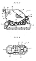
- FIG. 1 is a perspective view illustrative of the top surface side and one side in the left-and-right direction of a lever-type connector according to the embodiment of the present invention.
- FIG. 2 is a perspective view illustrative of the bottom surface side and the other side in the left-and-right direction of the lever-type connector of FIG. 1 .
- FIG. 3 is a plan view of the lever-type connector of FIG. 1 .
- FIG. 4 is a side view of one side in the left-and-right direction of the lever-type connector of FIG. 1 .
- FIG. 5 is a side view of the other side in the left-and-right direction of the lever-type connector of FIG. 1 .
- FIG. 6 is a back view of the lever-type connector of FIG. 1 .
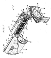
- FIG. 7 is a perspective view of the lever-type connector of FIG. 1 in a disassembled state.
- FIG. 8 is an enlarged rear view illustrative of an end of a lever provided to the
- FIG. 9 is a perspective view illustrative of the top and one side in the left-and-right direction in a state midway through attaching a wire cover to a housing.
- FIG. 10 is a perspective view illustrative of the bottom and the other side in the left-and-right direction in a state midway through attaching the wire cover to the housing.
- FIG. 11 is a perspective view illustrative of a state where attachment of the wire cover to the housing is completed, and a lever is not attached.
- FIG. 12 is a perspective view illustrative of a state midway through sandwiching the rear surface side of the wire cover by both side plates of the lever.
- FIG. 13 is a perspective view illustrative of a state where the rear surface side of the wire cover is sandwiched by both side plates of the lever.
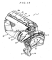
- FIG. 14 is a perspective view illustrative of a state where assembly of the lever-type connector is completed.
- FIG. 15 is a perspective view illustrative of a state midway through removing the lever from the wire cover.
- FIG. 16 is a perspective view illustrative of a state where removal of the lever from the wire cover is completed.
- FIG. 17 is a perspective view illustrative of a state midway through reattaching the lever to the wire cover.
- FIG. 18 is a plan view illustrative of a lever-type connector in a state where a lever is turned to a final position on the rear side.
- FIG. 19 is a plan view illustrative of a lever-type connector in a state where a lever is turned to a final position on the front side.
- FIG. 20 is a cross-sectional view of the lever-type connector of FIG. 19 .
- the lever-type connector 1 shown in FIGS. 1 to 7 includes a housing 10, which accommodates multiple contacts (not illustrated in the drawings), a wire cover 20, which is attached to the rear surface side (upper side in FIG. 3 ) of the housing 10, and a lever 30, which is attached to the housing 10.
- the housing 10 is formed extending in the left-and-right direction (left-and-right direction in FIG. 3 ), and has multiple contact receiving holes 11, which pass through in the front-and-rear direction (up-and-down direction in FIG. 3 ), as shown in FIG. 7 .
- a slider accommodating slot 12 extending in the left-and-right direction on either inner surface of the housing 10 in the up-and-down direction (up-and-down direction in FIG. 4 and FIG. 5 ) is provided.
- a slider 13 is accommodated in each of the sliding accommodating slots 12 so as to move freely in the left-and-right direction. As shown in FIG.
- a pair of pivot receiving portions 16 respectively join to a pivot 34 described later of the lever 30 is provided on an end in the left-and-right direction of the housing 10.
- a latch arm 16a for locking the pivot 34 of the lever joined to each of the pivot receiving portions 16 is provided at the rear of each of the bearings of the housing 10.
- Fixed pieces 17 for fixing the wire cover 20 are provided on either end in the left-and-right direction of the rear surface of the housing, as shown in FIG. 7 . Both of the fixed pieces 17 are provided protruding toward the rear, extending in the left-and-right direction.
- Multiple (four in this embodiment) fixing projection portions 17a, which protrude toward the outside, are provided in the left-and-right direction on the outer side surface in the left-and-right direction of each of the fixed pieces 17.
- Each of the sliders 13 is formed in a plate shape, extending in the left-and-right direction.
- Multiple cam grooves (not illustrated in the drawings), which lead in and push out cam pins (not illustrated in the drawings) provided on a mating connector, are provided in the left-and-right direction of the inner surface of each of the sliders 13.
- projection receiving portions 15 respectively joined to a slider moving projection 35 described later of the lever 30 are each provided on an end in the left-and-right direction of each of the sliders 13.
- the lever 30 is formed in a U shape and includes a connecting part 33 for connecting a pair of side plates 32 extending in the left-and-right direction and connecting the other ends of both of the side plates 32 to each other.
- the slider moving projection 35 which joins to the projection receiving portion 15 of each of the sliders 13, is formed protruding outward on the outer surface of an end of both of the side plates 32, as shown in FIG. 7 and FIG. 8 .
- the pivot 34 which joins to each of the pivot receiving portions 16 of the housing 10, is provided protruding inward on the inner surface of the end of both of the side plates 32.
- connecting plates 37 each extending inward are provided on the inner surface of the end of both of the side plates 32, as shown in FIG. 8 .
- Respective ends of both of the side plates 32 are joined to each other by a depression 37a provided at the end of the connecting plate 37 of one of the side plates 32 and a projection 37b provided on end of connecting plate 37 of the other side plate 32.
- a flat part 38 which makes contact with a slant face 50a described later of the wire cover 20 when removing the lever 30 from the housing 10, is formed on the inner surface on an end side of each of the side plates 32.
- notches 39 each extending in the left-and-right direction are provided on the inner surface of both of the side plates 32.
- a depression 33a to which a lock piece 27b of a lock member 27 described later of the wire cover 20 is latched is provided to the connecting part 33.
- the wire cover 20 includes a main body 21, which covers electrical wires (not illustrated in the drawings) connected to the contacts accommodated in the housing 10, a deterring section 22, which is provided on a side in the left-to-right direction of the main body 21, and a first tapered portion 50, which is formed between the main body 21 and the deterring section 22. Thickness in the up-and-down direction of the main body 21 is less than distance between both of the side plates 32 of the lever 30. Meanwhile, thickness in the up-and-down direction of the deterring section 22 is greater than the distance between both of the side plates 32 of the lever 30. As a result, the deterring section 22 deters the lever 30 that has been rotated until the final position (see FIG. 18 ) at the rear from rotating further toward the rear.
- the first tapered portion 50 is formed so as to connect to the main body 21 and the deterring section 22.
- the first tapered portion 50 includes a slanted face 50a, which continues to the top surface of the main body 21 and the top surface of the deterring section 22, and a slanted face 50b, which continues to the bottom surface of the main body 21 and the bottom surface of the deterring section 22.
- the lock member 27 which prevents the lever 30 that has been rotated until the final position (see FIG. 19 and FIG. 20 ) on the front side from rotating toward the rear side, is provided on the rear surface of the main body 21.
- the lock member 27 is formed in a cantilever plate-spring form and extends from the rear side toward the front side of the connecting part 33 of the lever 30 positioned at the final position on the front side.
- the lock member 27 has a plate spring 27a, and a lock piece 27b and a release projection portion 27c provided on the outer surface of the plate spring 27a.
- the plate spring 27a is provided extending from the rear toward the front of the connecting part 33 of the lever 30 positioned at the final position on the front side.
- the lock piece 27b is provided for latching onto the depression 33a of the connecting part 33 of the lever 30 positioned at the final position on the front side.
- the release projection portion 27c is provided so as to be positioned on the front side of the connecting part 33 of the lever 30 positioned at the final position on the front side.
- Lock projection portions 28, which prevent the lever 30 that has been rotated until the final position on the front side from rotating toward the rear, are provided on the top surface and the bottom surface of the main body 21.
- Each of the lock projection portions 28 is provided for latching onto the sides of the notches 39 of each of the side plates 32 of the lever 30 positioned at the final position on the rear side.
- Fixed parts 29 for fixing the wire cover 20 to the housing 10 are provided on the front end of the top surface and the front end of the bottom surface of the main body 21, as shown in FIG. 7 . Both of the fixed parts 29 are provided extending in the left-and-right direction. Both of the fixed parts 29 are provided so as to protrude outward in the up-and-down direction.
- a fixing groove 29a into which the fixing projection portions 17a of the housing 10 are inserted is provided to the respective inner surfaces of the fixed parts 29 in the left-and-right direction.
- a latch arm 29b is provided on the other end in the left-and-right direction of each of the fixed parts 29. Projections (not illustrated in the drawings) for latching onto the side of the fixing projection portions 17a of the housing 10 are provided on each of the latch arms 29.
- a second tapered portion 51 which has a thickness in the up-and-down direction that gradually decreases toward the outer side, is formed on the rear surface of the main body 21.
- the wire cover 20 is attached to the housing 10 which accommodates the multiple contacts.
- the wire cover 20 arranged on the rear side of the housing 10 is slid from one side to the other side in the left-and-right direction of the housing 10, as shown in FIG. 9 and FIG. 10 .
- the multiple fixing projection portions 17a of both of the fixed pieces 17 of the housing 10 are inserted into the fixing grooves 29a of each of the fixed parts 29 of the wire cover 20.
- the multiple fixing projection portions 17a are inserted into the fixing grooves 29a from one side in the left-and-right direction of the fixing grooves 29a in order from those on the other side in the left-and-right direction.
- the projections which are provided on the latch arms 29b of the fixed parts 29, latching onto the sides on the other side in the left-and-right direction of the fixing projection portions 17a provided furthest on the other side in the left-and-right direction locks the wire cover 20.
- the bound, electrical wires connected to the multiple contacts accommodated in the housing 10 are lead out from the electrical wire outlet 24 of the wire cover 20.
- the lever 30 is then attached to the housing 10 to which the wire cover 20 is attached.
- the lever 30 When attaching the lever 30 to the housing 10 to which the wire cover 20 is attached, the lever 30 must be arranged in the wire cover 20 so as for both of the side plates 32 to bridge over the rear surface side of the wire cover 20 and sandwich the wire cover 20 in the up-and-down direction (thickness direction).
- the ends of both of the side plates 32 of the lever 30 are first spread manually, and the distance between the ends of the connecting plates 37 of both of the side plates 32 is one allowing insertion of the edge of the second tapered portion 51 of the wire cover 20.
- the edge of the second tapered portion 51 of the wire cover 20 is inserted into between the ends of both of the connecting plates 37.
- the second tapered portion 51 which has a thickness in the up-and-down direction that gradually decreases toward the outer rear surface side of the main body 21 of the wire cover 20, is formed in this manner. Accordingly, when a worker attaches the lever 30 to the housing 10, the ends of both of the side plates 32 should be spread such that the distance between the ends of the connecting plates 37 of both of the side plates 32 is one allowing insertion of the edge of the second tapered portion 51 of the wire cover 20.
- the second tapered portion 51 of the wire cover 20 pushes apart the ends of both of the side plates 32 of the lever 30 such that the distance between the ends of the connecting plates 37 of both of the side plates 32 is equivalent to thickness in the up-and-down direction of the main body 21 of the wire cover 20.
- the thickness of the end of the second tapered portion 51 of the wire cover 20 in the up-and-down direction is formed sufficiently less than that of the main body 21 in the up-and-down direction.
- both of the side plates 32 do not need to be spread until the distance between the ends of the connecting plates 37 of both of the side plates 32 is greater than thickness of the main body 21 of the wire cover 20 in the up-and-down direction.
- the lever 30 is formed such that the distance between the connecting plates 37 of both of the side plates 32 is equivalent to thickness of the wire cover 20 of the main body 21 in the up-and-down direction so as to be strong enough that it does not break the connecting part 33 even if it deforms it.
- lever-type connector 1 when attaching the lever 30 to the housing 10, excess spreading of the end of the lever 30 by the worker may be prevented, and thereby preventing damage to the lever 30.
- lever-type connector 1 With the lever-type connector 1, it is necessary to remove the wire cover 20 from the housing 10 so as to expose the contact accommodated in the housing 10 in order to replace the contact. Moreover, with the lever-type connector 1, in order to remove the wire cover 20 from the housing 10, it is necessary to remove the lever 30, which is arranged bridging the rear surface side of the wire cover 20, from the wire cover 20.
- the lever 30 When replacing a contact of the lever-type connector 1, the lever 30 is first removed from the wire cover 20 of the lever-type connector 1 in the assembled state shown in FIG. 14 .
- the lever 30 is pushed in to move the ends of both of the side plates 32 toward the rear side of the wire cover 20.
- the first tapered portion 50 continuing to the main body 21 is formed on the deterring section 22 in this manner. Therefore, the worker does not need to spread the ends of both of the side plates 32 when removing the lever 30 from the housing 10. Namely, the worker pushes the lever 30 in toward the rear of the wire cover 20, making the first tapered portion 50 of the wire cover 20 push apart the ends of both of the side plates 32 such that the distance between both of the side plates 32 is equivalent to thickness of the stopper 22 of the wire cover 20 in the up-and-down direction.
- the contact accommodated in the housing 10 is exposed by removing the wire cover 20 from the housing 10.
- the lock by the latch arm 29b of the wire cover 20 is released, and the wire cover 20 is slid from one side toward the other side in the left-and-right direction of the housing 10. This makes the wire cover 20 removed from the housing 10, allowing replacement of the contact accommodated in the housing 10, as shown in FIG. 7 .
- the wire cover 20 is reattached to the housing 10 in the aforementioned sequence.
- the lever 30 is then reattached to the housing 10 to which the wire cover 20 is mounted.
- the notches 39 of both of the side plates 32 of the lever 30 are brought into contact with the outer surface of the hood portion 25 of the deterring section 22 on the wire cover 20.
- the lever 30 is pushed inward so as to move the notches 39 of both of the side plates 32 of the lever 30 toward the front of the wire cover.
- the hood portion 50 is provided on the deterring section 22 in this manner. Therefore, the worker does not need to spread the ends of both of the side plates 32 when reattaching the lever 30 to the housing 10. Namely, the worker pushes the lever 30 in toward the front of the wire cover 20, making the hood 25 of the deterring section 22 of the wire cover 20 push apart the ends of both of the side plates 32 such that the distance between both of the side plates 32 is equivalent to thickness of the deterring section 22 of the wire cover 20 in the up-and-down direction.
- lever-type connector 1 when reattaching the lever 30 to the housing 10, excess spreading of the end of the lever 30 by the worker may be prevented, and thereby preventing damage to the lever 30.
- the lever 30 When mating the lever-type connector 1 to a mating connector, the lever 30 is first brought into a state of being rotated until the final position on the rear side, as shown in FIG. 18 .
- the lever 30 that is rotated until the final position on the rear side is in a state unable to be rotated any further toward the rear by the deterring section 22.
- the lever 30 that has been rotated until the final position on the rear side is in a state where rotation toward the front is intercepted by the lock projection portion 28 of the main body 21 of the wire cover 20 latching onto the sides of the notches 39 of both of the side plates of the lever 30.
- the sliders 13 are moved in the direction of coming out from the slider accommodating slot 12 of the housing 10 so as to allow insertion of cam pins provided on the mating connector into cam grooves of the sliders 13.
- the sliders 13 are moved in the direction of coming out from the slider accommodating slot 12 of the housing 10 so that the multiple cam grooves of the sliders 13 push out the cam pins that are provided to the mating connector toward the front.
- the mating of the contacts accommodated in the housing 10 of the lever-type connector 1 and the contacts accommodated in the mating connector is released.
- a lever-type connector according to the present invention prevents a worker from damaging a lever when removing the lever from a housing. Moreover, a lever-type connector prevents a worker from damaging a lever when attaching the lever to a housing.
Description
- The present invention relates to a lever-type connector to mate with and release from a mating connector by rotating a lever.
- In recent years, multipolarity in electric connectors used in the field of automobiles and the like has been advancing. With a multipolar electric connector, a large force is necessary to mate together connectors and release the connection. Therefore, in the field of automobiles and the like, a lever-type connector to mate with and release from a mating connector utilizing effect of boosting by a lever is used.
- Typically, a lever of a lever-type connector is formed in a U shape and has a pair of side plates and a connecting part for connecting the pair of side plates to each other. Moreover, a rotating pivot for attaching a lever to a housing is provided on each of inner surfaces of ends of both side plates. When attaching the lever to the housing, a worker must spread the ends of the lever manually to join both of the rotating pivots to the bearings of the housing, respectively. As a result, with a lever-type connector, when attaching the lever to the housing, there is a problem that the worker damages the lever by spreading the ends of the lever too much.
- Particularly, with a lever-type connector formed multipolar, there are cases where reactive force developed when mating with a mating connector increases and bending of the lever occurs. If bending of the lever occurs when mating a lever-type connector with a mating connector, the mating with the mating connector is incomplete. The lever is made of a hard material in order to prevent bending of the lever from occurring when mating a lever-type connector formed multipolar with a mating connector. However, if the lever is made of a hard material, cracking of the lever easily occurs when the worker is spreading the end of the lever.
- As a result, a lever-type connector capable of preventing the worker from damaging the lever when attaching the lever to the housing has been developed.
- As a conventional lever-type connector capable of reducing damages to the lever by the worker when attaching the lever to the housing, for example, the connector shown in
FIG. 21 is well-known (see Patent Document 1). -
FIG. 21 is a plan view of a conventional lever-type connector. - A lever-
type connector 100 shown inFIG. 21 includes aconnector housing 110, and alever 120 attached rotatable in theconnector housing 110. - The
connector housing 110 includes a terminal accommodatingportion 111 for accommodating a terminal, and anouter tube 112 encompassing theterminal accommodating portion 111. Alever installing part 113 for installing thelever 120 is provided on either side of theouter tube 112. Both of thelever installing parts 113 are formed in a pouch form opening toward the front. A lead-ingroove 114 extending in the front-and-rear direction (up-and-down direction shown inFIG. 21 ) is formed on either side of both of thelever installing parts 113. Apivot receiving portion 115 for holding a rotatingpivot 123 of thelever 120 is provided on each back end of the respective lead-ingrooves 114. - The
lever 120 is overall formed in a U shape and includes a pair of side plates 121 (only one is shown in the drawing) and a connectingpart 122 for connecting ends of theside plates 121 to each other. The rotating pivot123 is provided protruding inward on respective inner surfaces of the ends of theside plates 121. In addition, agear piece 124 for joining to agear part 210 of amating connector 200 is provided at the outer circumference of the respective rotatingpivots 123. - When attaching the
lever 120 to theconnector housing 110, first, spread the end of thelever 120, and insert both of the rotatingpivots 123 of thelever 120 in the lead-ingrooves 114 of thelever installing part 113 in theconnector housing 110, respectively. Next, the end of thelever 120 is moved while aligning the inner surface of both of theside plates 121 with the outer surface of thelever installing parts 113 of theconnector housing 10, and the rotatingpivots 123 of both of theside plates 121 are joined to thepivot receiving portions 115 of thelever installing parts 113, respectively. - In this manner, with the lever-
type connector 100, the worker does not need to perform the operation of spreading the end of thelever 120 and operation of moving thelever 120 to a predetermined position simultaneously. As a result, the worker may be dedicated to the operation of moving the lever to a predetermined position. - Accordingly, with the lever-
type connector 100, provision of thelever installing parts 113 formed in a pouch shape allows easy application of the U-shapedlever 120 to theconnector housing 110.
Patent Document 1: Unexamined Patent Application Publication No.2006-147492 - However, with the lever-
type connector 100 shown inFIG. 21 , means for aggressively spreading the end of thelever 120 is not provided, and is only a connector for maintaining a state in which the end of thelever 120 is spread. - Accordingly, with the lever-
type connector 100, damage of thelever 120 cannot be prevented when the worker spreads the end of thelever 120. - Moreover, there are cases where a contact may be replaced during maintenance of a lever-type connector onboard an automobile or the like.
- In particular, with a lever-type connector having a wire cover, which covers electrical wires connected to contacts accommodated in a housing, the worker must remove the levers and the wire cover from the housing manually when replacing a contact.
- A further prior art a lever-type connector, [on which the preamble of claim 1 is based] is disclosed in patent
WO 2007/044393 A2 . The connector includes a housing containing contacts and a wire cover connected to a rear of the housing. A mate-assist lever is pivotably mounted on the housing and has a pair of side plates, ends of which pivotably engage the housing, and a connecting part which interconnects the side plates. - As a result, with a lever-type connector with a wire cover, when removing the lever from the housing, there is a problem that the worker damages the lever by spreading the end of the lever too much.
-
Document DE 10 2004 061 531 A1 discloses a plug-in connector comprising a housing provided with axially aligned axial bolts arranged on opposite sides, and a U-shaped lever that can be connected to the axial bolts in an articulated manner. Cams are respectively arranged on the opposing sides of the housing, the limbs of the lever sliding over said cams during the assembly of the lever, and widening in such a way that the free ends thereof are lifted far enough above the lateral surfaces that they can be pushed over the axial bolts. The inner sides of the limbs are provided with recesses which are used to receive the cams when axle bearing recesses on the free ends of the limbs are located over the axial bolts such that the axial bolts can engage in each other. - The present invention has been made to solve the above problems in the conventional technique, and it is an objective of the present invention to provide a lever-type connector capable of preventing a worker from damaging a lever when removing the lever from a housing.
- According to the present invention there is provided a lever-type connector comprising: a housing that accommodates a contact; a wire cover that is attached to a rear surface side of the housing and that covers an electrical wire connected to the contact accommodated in the housing; and a lever formed in a U shape and having a pair of side plates and a connecting part that connects the pair of side plates to each other, wherein the lever is attached rotatably relative to the housing in a state where the lever bridges over the rear surface side of the wire cover and where both of the side plates sandwich the wire cover in the thickness direction, characterised in that the wire cover comprises a main body, which is formed to have a smaller thickness than distance between both of the side plates, a deterring section, which deters rotation of the lever and is formed to have a greater thickness than the distance between both of the side plates, and a first tapered portion, which is formed between the main body and the deterring section, the first tapered portion arranged to spread apart both of the side plates if both of the side plates are moved along the first tapered portion when removing the lever from the housing..
- Therefore, according to the lever-type connector according to the present invention, prevention of a worker from damaging the lever is possible since it is unnecessary for the worker to spread the end of the lever manually when removing the lever from the housing.
-
-
FIG. 1 is a perspective view illustrative of the top surface side and one side in the left-and-right direction of a lever-type connector according to an embodiment of the present invention; -
FIG. 2 is a perspective view illustrative of the bottom surface side and the other side in the left-and-right direction of the lever-type connector ofFIG. 1 ; -
FIG. 3 is a plan view of the lever-type connector ofFIG. 1 ; -
FIG. 4 is a side view of one side in the left-and-right direction of the lever-type connector ofFIG. 1 ; -
FIG. 5 is a side view of the other side in the left-and-right direction of the lever-type connector ofFIG. 1 ; -
FIG. 6 is a rear view of the lever-type connector ofFIG. 1 ; -
FIG. 7 is a perspective view of the lever-type connector ofFIG. 1 in a disassembled state; -
FIG. 8 is an enlarged rear view illustrative of an end of a lever provided to the lever-type connector ofFIG. 1 ; -
FIG. 9 is a perspective view illustrative of the top surface side and one side in the left-and-right direction in a state midway through attaching a wire cover to a housing; -
FIG. 10 is a perspective view illustrative of the bottom surface side and the other side in the left-and-right direction in a state midway through attaching the wire cover to the housing; -
FIG. 11 is a perspective view illustrative of a state where attachment of the wire cover to the housing is completed, and a lever is not attached; -
FIG. 12 is a perspective view illustrative of a state midway through sandwiching the rear surface side of the wire cover by both side plates of the lever; -
FIG. 13 is a perspective view illustrative of a state where the rear surface side of the wire cover is sandwiched by both side plates of the lever; -
FIG. 14 is a perspective view illustrative of a state where assembly of the lever-type connecter is completed; -
FIG. 15 is a perspective view illustrative of a state midway through removing the lever from the wire cover; -
FIG. 16 is a perspective view illustrative of a state where removal of the lever from the wire cover is completed; -
FIG. 17 is a perspective view illustrative of a state midway through reattaching the lever to the wire cover; -
FIG. 18 is a plan view illustrative of a lever-type connector in a state where a lever is turned to a final position on the rear side; -
FIG. 19 is a plan view illustrative of a lever-type connector in a state where a lever is turned to a final position on the front side; -
FIG. 20 is a cross-sectional view of the lever-type connector ofFIG. 19 ; and -
FIG. 21 is a plan view of a conventional lever-type connector. -
- 1:
- lever-type connector
- 10:
- housing
- 11:
- contact receiving hole
- 12:
- slider accommodating slot
- 13:
- slider
- 15:
- projection receiving portion
- 16:
- pivot receiving portion
- 16a:
- latch arm
- 17:
- fixed piece
- 17a:
- fixing projection portion
- 20:
- wire cover
- 21:
- main body
- 22:
- deterring section
- 24:
- electrical wire outlet
- 25:
- hood portion
- 27:
- lock member
- 27a:
- plate spring
- 27b:
- lock piece
- 27c:
- release projection portion
- 28:
- lock projection portion
- 29:
- fixed part
- 29a:
- fixing groove
- 29b:
- latch arm
- 30:
- lever
- 32:
- side plate
- 33:
- connecting part
- 33a:
- depression
- 34:
- pivot
- 35:
- slider moving projection
- 37:
- connecting plate
- 37a:
- depression
- 37b:
- projection
- 38:
- flat part
- 39:
- notch
- 50:
- first tapered portion
- 50a:
- slant face
- 50b:
- slant face
- 51:
- second tapered portion
- Hereinafter, a lever-type connector or an embodiment of the present invention will be described with reference to the drawings.
-
FIG. 1 is a perspective view illustrative of the top surface side and one side in the left-and-right direction of a lever-type connector according to the embodiment of the present invention.FIG. 2 is a perspective view illustrative of the bottom surface side and the other side in the left-and-right direction of the lever-type connector ofFIG. 1 .FIG. 3 is a plan view of the lever-type connector ofFIG. 1 .FIG. 4 is a side view of one side in the left-and-right direction of the lever-type connector ofFIG. 1 .FIG. 5 is a side view of the other side in the left-and-right direction of the lever-type connector ofFIG. 1 .FIG. 6 is a back view of the lever-type connector ofFIG. 1 .FIG. 7 is a perspective view of the lever-type connector ofFIG. 1 in a disassembled state.FIG. 8 is an enlarged rear view illustrative of an end of a lever provided to the lever-type connector ofFIG. 1 . -
FIG. 9 is a perspective view illustrative of the top and one side in the left-and-right direction in a state midway through attaching a wire cover to a housing.FIG. 10 is a perspective view illustrative of the bottom and the other side in the left-and-right direction in a state midway through attaching the wire cover to the housing.FIG. 11 is a perspective view illustrative of a state where attachment of the wire cover to the housing is completed, and a lever is not attached.FIG. 12 is a perspective view illustrative of a state midway through sandwiching the rear surface side of the wire cover by both side plates of the lever.FIG. 13 is a perspective view illustrative of a state where the rear surface side of the wire cover is sandwiched by both side plates of the lever.FIG. 14 is a perspective view illustrative of a state where assembly of the lever-type connector is completed.FIG. 15 is a perspective view illustrative of a state midway through removing the lever from the wire cover.FIG. 16 is a perspective view illustrative of a state where removal of the lever from the wire cover is completed.FIG. 17 is a perspective view illustrative of a state midway through reattaching the lever to the wire cover.FIG. 18 is a plan view illustrative of a lever-type connector in a state where a lever is turned to a final position on the rear side.FIG. 19 is a plan view illustrative of a lever-type connector in a state where a lever is turned to a final position on the front side.FIG. 20 is a cross-sectional view of the lever-type connector ofFIG. 19 . - The lever-type connector 1 shown in
FIGS. 1 to 7 includes ahousing 10, which accommodates multiple contacts (not illustrated in the drawings), awire cover 20, which is attached to the rear surface side (upper side inFIG. 3 ) of thehousing 10, and alever 30, which is attached to thehousing 10. - The
housing 10 is formed extending in the left-and-right direction (left-and-right direction inFIG. 3 ), and has multiplecontact receiving holes 11, which pass through in the front-and-rear direction (up-and-down direction inFIG. 3 ), as shown inFIG. 7 . As shown inFIG. 2 andFIG. 5 , aslider accommodating slot 12 extending in the left-and-right direction on either inner surface of thehousing 10 in the up-and-down direction (up-and-down direction inFIG. 4 andFIG. 5 ) is provided. Aslider 13 is accommodated in each of the slidingaccommodating slots 12 so as to move freely in the left-and-right direction. As shown inFIG. 7 , a pair ofpivot receiving portions 16 respectively join to apivot 34 described later of thelever 30 is provided on an end in the left-and-right direction of thehousing 10. A latch arm 16a for locking thepivot 34 of the lever joined to each of thepivot receiving portions 16 is provided at the rear of each of the bearings of thehousing 10.Fixed pieces 17 for fixing thewire cover 20 are provided on either end in the left-and-right direction of the rear surface of the housing, as shown inFIG. 7 . Both of the fixedpieces 17 are provided protruding toward the rear, extending in the left-and-right direction. Multiple (four in this embodiment) fixingprojection portions 17a, which protrude toward the outside, are provided in the left-and-right direction on the outer side surface in the left-and-right direction of each of the fixedpieces 17. - Each of the
sliders 13 is formed in a plate shape, extending in the left-and-right direction. Multiple cam grooves (not illustrated in the drawings), which lead in and push out cam pins (not illustrated in the drawings) provided on a mating connector, are provided in the left-and-right direction of the inner surface of each of thesliders 13. Moreover, as shown inFIG. 7 ,projection receiving portions 15 respectively joined to aslider moving projection 35 described later of thelever 30 are each provided on an end in the left-and-right direction of each of thesliders 13. - The
lever 30 is formed in a U shape and includes a connectingpart 33 for connecting a pair ofside plates 32 extending in the left-and-right direction and connecting the other ends of both of theside plates 32 to each other. - The
slider moving projection 35, which joins to theprojection receiving portion 15 of each of thesliders 13, is formed protruding outward on the outer surface of an end of both of theside plates 32, as shown inFIG. 7 andFIG. 8 . Thepivot 34, which joins to each of thepivot receiving portions 16 of thehousing 10, is provided protruding inward on the inner surface of the end of both of theside plates 32. Moreover, connectingplates 37 each extending inward are provided on the inner surface of the end of both of theside plates 32, as shown inFIG. 8 . Respective ends of both of theside plates 32 are joined to each other by adepression 37a provided at the end of the connectingplate 37 of one of theside plates 32 and aprojection 37b provided on end of connectingplate 37 of theother side plate 32. Furthermore, aflat part 38, which makes contact with aslant face 50a described later of thewire cover 20 when removing thelever 30 from thehousing 10, is formed on the inner surface on an end side of each of theside plates 32. In addition,notches 39 each extending in the left-and-right direction are provided on the inner surface of both of theside plates 32. - As shown in
FIG. 1 , adepression 33a to which alock piece 27b of alock member 27 described later of thewire cover 20 is latched is provided to the connectingpart 33. - The
wire cover 20 includes amain body 21, which covers electrical wires (not illustrated in the drawings) connected to the contacts accommodated in thehousing 10, a deterringsection 22, which is provided on a side in the left-to-right direction of themain body 21, and a first taperedportion 50, which is formed between themain body 21 and the deterringsection 22. Thickness in the up-and-down direction of themain body 21 is less than distance between both of theside plates 32 of thelever 30. Meanwhile, thickness in the up-and-down direction of the deterringsection 22 is greater than the distance between both of theside plates 32 of thelever 30. As a result, the deterringsection 22 deters thelever 30 that has been rotated until the final position (seeFIG. 18 ) at the rear from rotating further toward the rear. - An
electrical wire outlet 24, which leads out the electrical wires connected to the contacts that are accommodated in thehousing 10, is provided on an end of the deterringsection 22 in the left-and-right direction. Moreover, ahood portion 25 protruding toward one side in the left-and-right direction is provided circumferentially to theelectrical wire outlet 24 of the deterringsection 22. The outer surface of thehood portion 25 is formed in an arc shape. - The first tapered
portion 50 is formed so as to connect to themain body 21 and the deterringsection 22. The first taperedportion 50 includes a slantedface 50a, which continues to the top surface of themain body 21 and the top surface of the deterringsection 22, and aslanted face 50b, which continues to the bottom surface of themain body 21 and the bottom surface of the deterringsection 22. - As shown in
FIG. 2 , thelock member 27, which prevents thelever 30 that has been rotated until the final position (seeFIG. 19 and FIG. 20 ) on the front side from rotating toward the rear side, is provided on the rear surface of themain body 21. Thelock member 27 is formed in a cantilever plate-spring form and extends from the rear side toward the front side of the connectingpart 33 of thelever 30 positioned at the final position on the front side. Thelock member 27 has aplate spring 27a, and alock piece 27b and arelease projection portion 27c provided on the outer surface of theplate spring 27a. Theplate spring 27a is provided extending from the rear toward the front of the connectingpart 33 of thelever 30 positioned at the final position on the front side. Thelock piece 27b is provided for latching onto thedepression 33a of the connectingpart 33 of thelever 30 positioned at the final position on the front side. Therelease projection portion 27c is provided so as to be positioned on the front side of the connectingpart 33 of thelever 30 positioned at the final position on the front side. -
Lock projection portions 28, which prevent thelever 30 that has been rotated until the final position on the front side from rotating toward the rear, are provided on the top surface and the bottom surface of themain body 21. Each of thelock projection portions 28 is provided for latching onto the sides of thenotches 39 of each of theside plates 32 of thelever 30 positioned at the final position on the rear side. -
Fixed parts 29 for fixing thewire cover 20 to thehousing 10 are provided on the front end of the top surface and the front end of the bottom surface of themain body 21, as shown inFIG. 7 . Both of the fixedparts 29 are provided extending in the left-and-right direction. Both of the fixedparts 29 are provided so as to protrude outward in the up-and-down direction. A fixinggroove 29a into which the fixingprojection portions 17a of thehousing 10 are inserted is provided to the respective inner surfaces of the fixedparts 29 in the left-and-right direction. Alatch arm 29b is provided on the other end in the left-and-right direction of each of the fixedparts 29. Projections (not illustrated in the drawings) for latching onto the side of the fixingprojection portions 17a of thehousing 10 are provided on each of thelatch arms 29. - A second tapered
portion 51, which has a thickness in the up-and-down direction that gradually decreases toward the outer side, is formed on the rear surface of themain body 21. - An assembling method of the lever-type connector 1 will now be described.
- When assembling the lever-type connector 1, contacts respectively connected to electrical wires (not illustrated in the drawings) are accommodated in the multiple
contact receiving holes 11 of thehousing 10 of the lever-type connector 1 in the disassembled state shown inFIG. 7 . Moreover, therespective sliders 13 are inserted into both of theslider accommodating slots 12 of thehousing 10. - Next, the
wire cover 20 is attached to thehousing 10 which accommodates the multiple contacts. When attaching thewire cover 20 to thehousing 10, thewire cover 20 arranged on the rear side of thehousing 10 is slid from one side to the other side in the left-and-right direction of thehousing 10, as shown inFIG. 9 andFIG. 10 . As a result, the multiplefixing projection portions 17a of both of the fixedpieces 17 of thehousing 10 are inserted into the fixinggrooves 29a of each of the fixedparts 29 of thewire cover 20. At this time, the multiplefixing projection portions 17a are inserted into the fixinggrooves 29a from one side in the left-and-right direction of the fixinggrooves 29a in order from those on the other side in the left-and-right direction. Once thewire cover 20 slides and the sides of the fixingprojection portions 17a provided furthest on the other side in the left-and-right direction bump into wall surfaces on the other side in the left-and-right direction of the fixinggrooves 29a, attachment of thewire cover 20 to thehousing 10 is complete, as shown inFIG. 11 . - In the state where attachment of the
wire cover 20 to thehousing 10 is complete, the projections, which are provided on thelatch arms 29b of the fixedparts 29, latching onto the sides on the other side in the left-and-right direction of the fixingprojection portions 17a provided furthest on the other side in the left-and-right direction locks thewire cover 20. Moreover, in the state where attachment of thewire cover 20 to thehousing 10 is complete, the bound, electrical wires connected to the multiple contacts accommodated in thehousing 10 are lead out from theelectrical wire outlet 24 of thewire cover 20. - The
lever 30 is then attached to thehousing 10 to which thewire cover 20 is attached. When attaching thelever 30 to thehousing 10 to which thewire cover 20 is attached, thelever 30 must be arranged in thewire cover 20 so as for both of theside plates 32 to bridge over the rear surface side of thewire cover 20 and sandwich thewire cover 20 in the up-and-down direction (thickness direction). - Accordingly, when attaching the
lever 30 to thehousing 10, as shown inFIG. 11 , the ends of both of theside plates 32 of thelever 30 are first spread manually, and the distance between the ends of the connectingplates 37 of both of theside plates 32 is one allowing insertion of the edge of the second taperedportion 51 of thewire cover 20. In the state where the ends of both of theside plates 32 of thelever 30 are spread manually, the edge of the second taperedportion 51 of thewire cover 20 is inserted into between the ends of both of the connectingplates 37. - Once the edge of the second tapered
portion 51 of thewire cover 20 is inserted into between the ends of the connectingplates 37 of both of theside plates 32 of thelever 30, spreading of both of theside plates 32 is stopped manually, and both of theconnection plates 37 are then brought into contact with the surface of the second taperedportion 51. Thelever 30 is pushed in to move the ends of the connectingplates 37 of both of theside plates 32 toward the front side of thewire cover 20. - Once the
lever 30 is pushed in, the ends of the connectingplates 37 of both of theside plates 32 move along the surface of the second taperedportion 51. The second taperedportion 51 of thewire cover 20 then pushes apart the ends of both of theside plates 32 of thelever 30. - Once the
lever 30 is pushed further inward, the ends of the connectingplates 37 of both of theside plates 32 move from the surface of the second taperedportion 51 of thewire cover 20 to the surface of themain body 21. Afterward, the ends of the connectingplates 37 of both of theside plates 32 on thelever 30 are moved along the surface of themain body 21 of thewire cover 20, as shown inFIG. 12 . - Once the
lever 30 is pushed further inward, the ends of the connectingplates 37 of both of theside plates 32 go over themain body 21 of thewire cover 20, as shown inFIG. 13 . Deformation of the connectingparts 33 of thelever 30 returns to the normal formation again, and thedepression 37a provided on the end of the connectingplate 37 of one of theside plates 32 and theprojection 37b provided on end of connectingplate 37 of theother side plate 32 are connected. As a result, thelever 30 is arranged in thewire cover 20 in a state where both of theside plates 32 bridge over the rear surface side of thewire cover 20, and both of theside plates 32 sandwich thewire cover 20 in the up-and-down direction. - Then, the
pivots 34 of both of theside plate 32 on thelever 30 are mated to respectivepivot receiving portion 16 of thehousing 10, and theslider moving projection 35 of therespective side plates 32 of thelever 30 is connected to respectiveprojection receiving portions 15 of thesliders 13. This attaches thelever 30 to thewire cover 20, as shown inFIG. 14 , thereby completing assembly of the lever-type connector 1. - With the lever-type connector 1, the second tapered
portion 51, which has a thickness in the up-and-down direction that gradually decreases toward the outer rear surface side of themain body 21 of thewire cover 20, is formed in this manner. Accordingly, when a worker attaches thelever 30 to thehousing 10, the ends of both of theside plates 32 should be spread such that the distance between the ends of the connectingplates 37 of both of theside plates 32 is one allowing insertion of the edge of the second taperedportion 51 of thewire cover 20. By pushing thelever 30 inward thereafter, the second taperedportion 51 of thewire cover 20 pushes apart the ends of both of theside plates 32 of thelever 30 such that the distance between the ends of the connectingplates 37 of both of theside plates 32 is equivalent to thickness in the up-and-down direction of themain body 21 of thewire cover 20. - Here, the thickness of the end of the second tapered
portion 51 of thewire cover 20 in the up-and-down direction is formed sufficiently less than that of themain body 21 in the up-and-down direction. - Accordingly, when a worker attaches the
lever 30, both of theside plates 32 do not need to be spread until the distance between the ends of the connectingplates 37 of both of theside plates 32 is greater than thickness of themain body 21 of thewire cover 20 in the up-and-down direction. Moreover, thelever 30 is formed such that the distance between the connectingplates 37 of both of theside plates 32 is equivalent to thickness of thewire cover 20 of themain body 21 in the up-and-down direction so as to be strong enough that it does not break the connectingpart 33 even if it deforms it. - As a result, according to the lever-type connector 1, when attaching the
lever 30 to thehousing 10, excess spreading of the end of thelever 30 by the worker may be prevented, and thereby preventing damage to thelever 30. - Operation when replacing a contact of the lever-type connector 1 will be described next.
- With the lever-type connector 1, it is necessary to remove the wire cover 20 from the
housing 10 so as to expose the contact accommodated in thehousing 10 in order to replace the contact. Moreover, with the lever-type connector 1, in order to remove the wire cover 20 from thehousing 10, it is necessary to remove thelever 30, which is arranged bridging the rear surface side of thewire cover 20, from thewire cover 20. - When replacing a contact of the lever-type connector 1, the
lever 30 is first removed from thewire cover 20 of the lever-type connector 1 in the assembled state shown inFIG. 14 . - When removing the
lever 30 from thewire cover 20, thepivots 34 of both of theside plates 32 of thelever 30 are first removed from each of thebearings 16 of thehousing 10, as shown inFIG. 13 . Theslider moving projections 35 of both of theside plates 32 of thelever 30 are then removed from theprojection receiving portions 15 of each of thesliders 13. - Next, the
lever 30 is pushed in to move the ends of both of theside plates 32 toward the rear side of thewire cover 20. - Once the
lever 30 is pushed in, theflat portions 38 of both of theside plates 32 make contact with the second taperedportion 50 of thewire cover 20. Once thelever 30 is pushed further inward, theflat portions 38 of both of theside plates 32 move along the slanted faces 50a and 50b of the first taperedportion 50 of thewire cover 20, as shown inFIG. 15 . The first taperedportion 50 of thewire cover 20 then pushes apart the ends of both of theside plates 32 of thelever 30. - Once the
lever 30 is slid even further inward, the ends of both of theside plates 32 bridge over the deterringsection 22 of thewire cover 20, as shown inFIG. 16 . Deformation of the connectingparts 33 of thelever 30 returns to the normal formation again, and thedepression 37a provided at the end of the connectingplate 37 of one of theside plates 32 andprojection 37b provided on end of connectingplate 37 of theother side plate 32 are joined. This removes thelever 30 from thewire cover 20. In this case, although not illustrated in the drawings, thelever 30 is in a state where both of theside plates 32 bridge over the electrical wires that are lead out from theelectrical wire outlet 24 of thewire cover 20. - With the lever-type connector 1, the first tapered
portion 50 continuing to themain body 21 is formed on the deterringsection 22 in this manner. Therefore, the worker does not need to spread the ends of both of theside plates 32 when removing thelever 30 from thehousing 10. Namely, the worker pushes thelever 30 in toward the rear of thewire cover 20, making the first taperedportion 50 of thewire cover 20 push apart the ends of both of theside plates 32 such that the distance between both of theside plates 32 is equivalent to thickness of thestopper 22 of thewire cover 20 in the up-and-down direction. - As a result, according to the lever-type connector 1, when removing the
lever 30, excess spreading of the end of thelever 30 by the worker may be prevented, and thereby preventing damage to thelever 30. - Next, the contact accommodated in the
housing 10 is exposed by removing the wire cover 20 from thehousing 10. When removing the wire cover 20 from thehousing 10, the lock by thelatch arm 29b of thewire cover 20 is released, and thewire cover 20 is slid from one side toward the other side in the left-and-right direction of thehousing 10. This makes thewire cover 20 removed from thehousing 10, allowing replacement of the contact accommodated in thehousing 10, as shown inFIG. 7 . - After replacement of the contact accommodated in the
housing 10 is completed, thewire cover 20 is reattached to thehousing 10 in the aforementioned sequence. - The
lever 30 is then reattached to thehousing 10 to which thewire cover 20 is mounted. When reattaching thelever 30 to thehousing 10 to which thewire cover 20 is attached, thenotches 39 of both of theside plates 32 of thelever 30 are brought into contact with the outer surface of thehood portion 25 of the deterringsection 22 on thewire cover 20. Thelever 30 is pushed inward so as to move thenotches 39 of both of theside plates 32 of thelever 30 toward the front of the wire cover. - Once the
lever 30 is pushed in, thenotches 39 of both of theside plates 32 are moved along the arc-shaped outer surface of thehood portion 25 of the deterringsection 22 of thewire cover 20, as shown inFIG. 17 . Thehood portion 25 of thestopper 22 on thewire cover 20 then pushes apart the ends of both of theside plates 32 of thelever 30. - Once the
lever 30 is pushed even further inward, the ends of both of theside plates 32 go over the deterringsection 22 of thewire cover 20, as shown inFIG. 13 . Deformation of the connectingparts 33 of thelever 30 returns to the normal formation again, and thedepression 37a provided at the end of the connectingplate 37 of one of theside plates 32 andprojection 37b provided on end of connectingplate 37 of theother side plate 32 are joined. As a result, thelever 30 is arranged in thewire cover 20 in a state where both of theside plates 32 bridge over the rear surface side of thewire cover 20, and both of theside plates 32 sandwich thewire cover 20 in the up-and-down direction. - Then, the
pivots 34 of both of theside plate 32 on thelever 30 are joined to respectivepivot receiving portions 16 of thehousing 10, and the slider moving projections35 of both of theside plates 32 of thelever 30 are joined to respectiveprojection receiving portions 15 of thesliders 13. This attaches thelever 30 to thewire cover 20, as shown inFIG. 14 , thereby completing assembly of the lever-type connector 1. - With the lever-type connector 1, the
hood portion 50 is provided on the deterringsection 22 in this manner. Therefore, the worker does not need to spread the ends of both of theside plates 32 when reattaching thelever 30 to thehousing 10. Namely, the worker pushes thelever 30 in toward the front of thewire cover 20, making thehood 25 of the deterringsection 22 of thewire cover 20 push apart the ends of both of theside plates 32 such that the distance between both of theside plates 32 is equivalent to thickness of the deterringsection 22 of thewire cover 20 in the up-and-down direction. - As a result, according to the lever-type connector 1, when reattaching the
lever 30 to thehousing 10, excess spreading of the end of thelever 30 by the worker may be prevented, and thereby preventing damage to thelever 30. - Mechanism of the lever-type connector 1 will now be described.
- With the lever-type connector 1 in the assembled state shown in
FIG. 14 , if thelever 30 is rotated toward the front, thesliders 13 are moved in the direction of going into theslider accommodating slot 12 of thehousing 10. Moreover, if thelever 30 is rotated toward the rear, thesliders 13 are moved in the direction of coming out from theslider accommodating slot 12 of thehousing 10. - When mating the lever-type connector 1 to a mating connector, the
lever 30 is first brought into a state of being rotated until the final position on the rear side, as shown inFIG. 18 . Thelever 30 that is rotated until the final position on the rear side is in a state unable to be rotated any further toward the rear by the deterringsection 22. Moreover, thelever 30 that has been rotated until the final position on the rear side is in a state where rotation toward the front is intercepted by thelock projection portion 28 of themain body 21 of thewire cover 20 latching onto the sides of thenotches 39 of both of the side plates of thelever 30. Furthermore, in the state where thelever 30 has been rotated until the final position on the rear side, thesliders 13 are moved in the direction of coming out from theslider accommodating slot 12 of thehousing 10 so as to allow insertion of cam pins provided on the mating connector into cam grooves of thesliders 13. - Then, in the state where the
lever 30 has been rotated until the final position on the rear side, the cam pins provided on the mating connector are inserted into the multiple cam grooves of thesliders 13, temporarily mating the lever-type connector 1 and the mating connector. - Next, the lock of the
lever 30 by thelock projection portion 28 of themain body 21 of thewire cover 20 is released, and thelever 30 that has been rotated until the final position on the rear side is rotated toward the front. Once thelever 30 is rotated toward the front, thesliders 13 are moved in the direction of going into theslider accommodating slot 12 of thehousing 10 so that the cam grooves of thesliders 13 lead the cam pins that are provided to the mating connector toward the rear. As a result, the multiple contacts accommodated in thehousing 10 of the lever-type connector 1 are mated with contacts accommodated in the mating connector. - Once the
lever 30 is rotated until the final position on the front side, as shown inFIG. 19 and FIG. 20 , mating of the lever-type connector 1 and the mating connector is then complete. Thelever 30 that has been rotated until the final position on the front side is in a state unable to be rotated any further toward the front by bringing the sides of thenotches 39 of both of theside plates 32 in contact with the rear surface of the fixingparts 29 of thewire cover 20. Moreover, thelever 30 that has been rotated until the final position is in a state where rotation toward the rear is intercepted by thelock piece 27b of thelock member 27 latching onto thedepression 33a of the connectingpart 33, as shown inFIG. 20 . - Meanwhile, when releasing the mating of the lever-type connector 1 and the mating connector, the lock of the
lever 30 by thelock member 27 of thewire cover 20 is released, and thelever 30 that has been rotated until the final position on the front side is rotated toward the rear. When releasing the lock of thelever 30 by thelock member 27 of thewire cover 20, the releasingprojection portion 27c of thelock member 27 is pushed in, and theplate spring 27a is bent inward, thereby releasing the latch on thedepression 33a of the connectingpart 33 to thelever 30 of thelock piece 27b. - Once the
lever 30 is rotated toward the rear, thesliders 13 are moved in the direction of coming out from theslider accommodating slot 12 of thehousing 10 so that the multiple cam grooves of thesliders 13 push out the cam pins that are provided to the mating connector toward the front. As a result, the mating of the contacts accommodated in thehousing 10 of the lever-type connector 1 and the contacts accommodated in the mating connector is released. - Once the
lever 30 is rotated until the final position on the rear side, as shown inFIG. 18 , release of the mating of the lever-type connector 1 and the mating connector is then complete. - A lever-type connector according to the present invention prevents a worker from damaging a lever when removing the lever from a housing. Moreover, a lever-type connector prevents a worker from damaging a lever when attaching the lever to a housing.
Claims (1)
- A lever-type connector (1) comprising:a housing (10) that accommodates a contact;a wire cover (20) that is attached to a rear surface side of the housing (10) and that covers an electrical wire connected to the contact accommodated in the housing (10); anda lever (30) formed in a U shape and having a pair of side plates (32) and a connecting part (33) that connects the pair of side plates (32) to each other,wherein the lever (30) is attached rotatably relative to the housing (10) in a state where the lever (30) bridges over the rear surface side of the wire cover (20) and where both of the side plates (32) sandwich the wire cover (20) in the thickness direction,characterised in that the wire cover (20) comprises a main body (21), which is formed to have a smaller thickness than distance between both of the side plates (32), a deterring section (22), which deters rotation of the lever (30) and is formed to have a greater thickness than the distance between both of the side plates (32), and a first tapered portion (50), which is formed between the main body (21) and the deterring section (22), the first tapered portion (50) arranged to spread apart both of the side plates (32) if both of the side plates (32) are moved along the first tapered portion (50) when removing the lever (30) from the housing (10).
Applications Claiming Priority (2)
| Application Number | Priority Date | Filing Date | Title |
|---|---|---|---|
| JP2008087616A JP4468465B2 (en) | 2008-03-28 | 2008-03-28 | Lever type connector |
| PCT/JP2009/055274 WO2009119403A1 (en) | 2008-03-28 | 2009-03-18 | Lever type connector |
Publications (3)
| Publication Number | Publication Date |
|---|---|
| EP2276121A1 EP2276121A1 (en) | 2011-01-19 |
| EP2276121A4 EP2276121A4 (en) | 2013-05-15 |
| EP2276121B1 true EP2276121B1 (en) | 2015-09-09 |
Family
ID=41113600
Family Applications (1)
| Application Number | Title | Priority Date | Filing Date |
|---|---|---|---|
| EP09724788.6A Active EP2276121B1 (en) | 2008-03-28 | 2009-03-18 | Lever type connector |
Country Status (5)
| Country | Link |
|---|---|
| US (1) | US8057245B2 (en) |
| EP (1) | EP2276121B1 (en) |
| JP (1) | JP4468465B2 (en) |
| CN (2) | CN103178397B (en) |
| WO (1) | WO2009119403A1 (en) |
Families Citing this family (22)
| Publication number | Priority date | Publication date | Assignee | Title |
|---|---|---|---|---|
| US8414315B2 (en) * | 2008-05-06 | 2013-04-09 | Molex Incorporated | Lever type electrical connector |
| JP4523987B1 (en) * | 2009-02-27 | 2010-08-11 | タイコエレクトロニクスジャパン合同会社 | Connector with slide cam |
| JP5407959B2 (en) * | 2010-03-17 | 2014-02-05 | 住友電装株式会社 | connector |
| JP5407960B2 (en) * | 2010-03-17 | 2014-02-05 | 住友電装株式会社 | Lever type connector |
| JP5343902B2 (en) * | 2010-03-17 | 2013-11-13 | 住友電装株式会社 | connector |
| JP5588773B2 (en) * | 2010-07-28 | 2014-09-10 | タイコエレクトロニクスジャパン合同会社 | Wire cover, electrical connector |
| JP5624874B2 (en) | 2010-12-24 | 2014-11-12 | タイコエレクトロニクスジャパン合同会社 | Lever type connector, wire cover |
| JP5968605B2 (en) * | 2011-08-29 | 2016-08-10 | タイコエレクトロニクスジャパン合同会社 | Connector and electric wire cover with lever |
| US9142916B2 (en) * | 2013-03-15 | 2015-09-22 | Tyco Electronics Corporation | Connector assembly with receptacle carriers |
| KR101503507B1 (en) * | 2014-04-09 | 2015-03-18 | 주식회사 경신 | Connector for vehicle |
| JP6339873B2 (en) * | 2014-06-27 | 2018-06-06 | モレックス エルエルシー | connector |
| JP2016207414A (en) * | 2015-04-21 | 2016-12-08 | 住友電装株式会社 | connector |
| FR3044173B1 (en) * | 2015-11-20 | 2019-05-17 | Aptiv Technologies Limited | CONNECTOR WITH CONNECTION ASSEMBLY SLIDE AND GUIDE-CABLE HOOD |
| JP6275104B2 (en) * | 2015-12-11 | 2018-02-07 | 矢崎総業株式会社 | Connector structure |
| JP6222588B1 (en) * | 2016-10-14 | 2017-11-01 | 住友電装株式会社 | Lever type connector |
| JP2018181575A (en) * | 2017-04-12 | 2018-11-15 | タイコエレクトロニクスジャパン合同会社 | Electric connector |
| EP3392979B1 (en) * | 2017-04-19 | 2020-01-29 | Aptiv Technologies Limited | Electrical connector with lever and methods of assembling thereof |
| JP6564815B2 (en) * | 2017-06-26 | 2019-08-21 | 矢崎総業株式会社 | connector |
| JP6912443B2 (en) * | 2018-11-29 | 2021-08-04 | 矢崎総業株式会社 | Wire fixing structure, electrical junction box, and wire harness |
| JP7183871B2 (en) * | 2019-03-05 | 2022-12-06 | 住友電装株式会社 | lever type connector |
| JP7021150B2 (en) * | 2019-05-27 | 2022-02-16 | 矢崎総業株式会社 | How to assemble the lever type connector and the lever type connector |
| JP7249506B2 (en) * | 2019-10-18 | 2023-03-31 | 株式会社オートネットワーク技術研究所 | lever type connector |
Citations (1)
| Publication number | Priority date | Publication date | Assignee | Title |
|---|---|---|---|---|
| DE102004061531A1 (en) * | 2004-12-21 | 2006-06-29 | Fci | Connector with locking bracket with easier assembly |
Family Cites Families (30)
| Publication number | Priority date | Publication date | Assignee | Title |
|---|---|---|---|---|
| JP2762896B2 (en) * | 1993-06-14 | 1998-06-04 | 住友電装株式会社 | Lever connector |
| FR2717627B1 (en) * | 1994-03-21 | 1996-04-26 | Cinch Connecteurs Sa | Device for coupling two housing elements of an electrical connector. |
| EP0820647B1 (en) * | 1995-04-12 | 1999-07-28 | The Whitaker Corporation | Modular electrical connecting unit |
| US6039586A (en) * | 1996-09-06 | 2000-03-21 | The Whitaker Corporation | Lever type connector |
| US6270376B1 (en) * | 1998-02-19 | 2001-08-07 | Delphi Technologies, Inc. | Pre-staged dual lock multi-row electrical connection system |
| JP3252955B2 (en) * | 1998-05-21 | 2002-02-04 | 住友電装株式会社 | Lever connector |
| US5938458A (en) * | 1998-06-17 | 1999-08-17 | Molex Incorporated | Lever type electrical connector |
| IT1303186B1 (en) * | 1998-11-27 | 2000-10-30 | Framatome Connectors Italia | ELECTRIC CONNECTOR. |
| US6305957B1 (en) * | 2000-02-24 | 2001-10-23 | Delphi Technologies, Inc. | Electrical connector assembly |
| US6217354B1 (en) * | 2000-03-20 | 2001-04-17 | Molek Incorporated | Lever type electrical connector |
| US6666698B2 (en) * | 2000-08-17 | 2003-12-23 | Tyco Electronics Corporation | Arc limiting electrical connector assembly |
| JP3492309B2 (en) * | 2000-11-02 | 2004-02-03 | エフシーアイジャパン株式会社 | connector |
| DE10057428B4 (en) * | 2000-11-20 | 2006-05-18 | Ria-Btr Produktions-Gmbh | terminal |
| US6896531B2 (en) * | 2001-02-27 | 2005-05-24 | Delphi Technologies, Inc. | Electrical connector assembly |
| ITTO20010290A1 (en) * | 2001-03-27 | 2002-09-27 | Framatome Connectors Italia | ELECTRIC CONNECTOR. |
| FR2830133A1 (en) * | 2001-09-24 | 2003-03-28 | Framatome Connectors Int | CONNECTOR TO COUPLING ASSISTANCE DEVICE |
| US6682359B1 (en) * | 2002-12-06 | 2004-01-27 | Tyco Electronics Corporation | Electrical connector assembly with connection assurance features |
| US20040192090A1 (en) * | 2003-03-28 | 2004-09-30 | Flowers Robert J. | Lever type electrical connector with CPA member |
| US7070438B2 (en) * | 2004-03-31 | 2006-07-04 | Jst Corporation | Connector lever lock |
| US6899554B1 (en) * | 2004-04-19 | 2005-05-31 | Jst Corporation | Dual action mechanical assisted connector |
| JP2006147492A (en) | 2004-11-24 | 2006-06-08 | Sumitomo Wiring Syst Ltd | Connector |
| JP4306608B2 (en) * | 2004-12-28 | 2009-08-05 | 住友電装株式会社 | Split connector |
| ITTO20050089A1 (en) * | 2005-02-16 | 2006-08-17 | Fci Italia S P A | ELECTRIC CONNECTOR |
| JP4478060B2 (en) * | 2005-04-08 | 2010-06-09 | 矢崎総業株式会社 | Connector with cover |
| JP2006324227A (en) * | 2005-04-18 | 2006-11-30 | Yazaki Corp | Connector |
| US7361036B2 (en) * | 2005-10-06 | 2008-04-22 | Fci Americas Technology, Inc. | Electrical connector with lever and latch |
| SG135994A1 (en) * | 2006-03-17 | 2007-10-29 | J S T Mfg Co Ltd | Electric connector |
| DE102006058680A1 (en) * | 2006-12-13 | 2008-06-19 | Kostal Kontakt Systeme Gmbh | Electrical connector |
| JP4944052B2 (en) * | 2008-02-08 | 2012-05-30 | 矢崎総業株式会社 | Lever fitting type connector |
| JP4387438B2 (en) * | 2008-03-28 | 2009-12-16 | タイコエレクトロニクスアンプ株式会社 | Lever type connector |
-
2008
- 2008-03-28 JP JP2008087616A patent/JP4468465B2/en active Active
-
2009
- 2009-03-18 EP EP09724788.6A patent/EP2276121B1/en active Active
- 2009-03-18 CN CN201310077704.4A patent/CN103178397B/en active Active
- 2009-03-18 WO PCT/JP2009/055274 patent/WO2009119403A1/en active Application Filing
- 2009-03-18 CN CN2009801124831A patent/CN101981761B/en active Active
-
2010
- 2010-09-28 US US12/892,284 patent/US8057245B2/en active Active
Patent Citations (1)
| Publication number | Priority date | Publication date | Assignee | Title |
|---|---|---|---|---|
| DE102004061531A1 (en) * | 2004-12-21 | 2006-06-29 | Fci | Connector with locking bracket with easier assembly |
Also Published As
| Publication number | Publication date |
|---|---|
| JP2009245608A (en) | 2009-10-22 |
| US8057245B2 (en) | 2011-11-15 |
| CN101981761A (en) | 2011-02-23 |
| CN103178397B (en) | 2015-05-13 |
| CN101981761B (en) | 2013-09-11 |
| JP4468465B2 (en) | 2010-05-26 |
| WO2009119403A1 (en) | 2009-10-01 |
| CN103178397A (en) | 2013-06-26 |
| US20110014804A1 (en) | 2011-01-20 |
| EP2276121A1 (en) | 2011-01-19 |
| EP2276121A4 (en) | 2013-05-15 |
Similar Documents
| Publication | Publication Date | Title |
|---|---|---|
| EP2276121B1 (en) | Lever type connector | |
| EP2276123B1 (en) | Lever type connector | |
| EP2276122B1 (en) | Lever-type connector | |
| EP2224549B1 (en) | Lever-type connector, connector assembly and connecting method | |
| EP2658041B1 (en) | Lever-type connector | |
| EP1742302B1 (en) | A connector, connector assembly and assembling method therefor | |
| EP1800372B1 (en) | Locking device for connector elements and a connector provided with said device | |
| EP2131452B1 (en) | Lever type connector | |
| EP2278667A1 (en) | Lever type connector | |
| JP2882260B2 (en) | Lever connector | |
| US8419462B2 (en) | Lever type connector | |
| JP3275290B2 (en) | Lever connector | |
| EP3386040B1 (en) | Plug connector and method of producing a plug connection | |
| JP5172871B2 (en) | Lever type connector | |
| US20020064987A1 (en) | Low insertion force type connector | |
| JP2006338949A (en) | Connector fitting structure | |
| JP5052322B2 (en) | Lever type connector | |
| JP3494285B2 (en) | connector | |
| KR100920098B1 (en) | Lever Type Connector | |
| JP2004103557A (en) | Lever type insertion-coupling connector | |
| CN111052515B (en) | Plug connection for the automatic connection of at least two electrical conductors | |
| EP2557638B1 (en) | Lever-type connector and method of assembling it | |
| CN110120604B (en) | Connector component and connector | |
| JP3770454B2 (en) | Connector assembly | |
| JP2001338719A (en) | Connector device |
Legal Events
| Date | Code | Title | Description |
|---|---|---|---|
| PUAI | Public reference made under article 153(3) epc to a published international application that has entered the european phase |
Free format text: ORIGINAL CODE: 0009012 |
|
| 17P | Request for examination filed |
Effective date: 20101021 |
|
| AK | Designated contracting states |
Kind code of ref document: A1 Designated state(s): AT BE BG CH CY CZ DE DK EE ES FI FR GB GR HR HU IE IS IT LI LT LU LV MC MK MT NL NO PL PT RO SE SI SK TR |
|
| AX | Request for extension of the european patent |
Extension state: AL BA RS |
|
| DAX | Request for extension of the european patent (deleted) | ||
| A4 | Supplementary search report drawn up and despatched |
Effective date: 20130416 |
|
| RIC1 | Information provided on ipc code assigned before grant |
Ipc: H01R 13/629 20060101AFI20130410BHEP Ipc: H01R 13/516 20060101ALI20130410BHEP |
|
| 17Q | First examination report despatched |
Effective date: 20140310 |
|
| GRAP | Despatch of communication of intention to grant a patent |
Free format text: ORIGINAL CODE: EPIDOSNIGR1 |
|
| INTG | Intention to grant announced |
Effective date: 20150409 |
|
| GRAS | Grant fee paid |
Free format text: ORIGINAL CODE: EPIDOSNIGR3 |
|
| GRAA | (expected) grant |
Free format text: ORIGINAL CODE: 0009210 |
|
| AK | Designated contracting states |
Kind code of ref document: B1 Designated state(s): AT BE BG CH CY CZ DE DK EE ES FI FR GB GR HR HU IE IS IT LI LT LU LV MC MK MT NL NO PL PT RO SE SI SK TR |
|
| REG | Reference to a national code |
Ref country code: GB Ref legal event code: FG4D |
|
| REG | Reference to a national code |
Ref country code: AT Ref legal event code: REF Ref document number: 748814 Country of ref document: AT Kind code of ref document: T Effective date: 20150915 Ref country code: CH Ref legal event code: EP |
|
| REG | Reference to a national code |
Ref country code: IE Ref legal event code: FG4D |
|
| REG | Reference to a national code |
Ref country code: DE Ref legal event code: R096 Ref document number: 602009033516 Country of ref document: DE |
|
| REG | Reference to a national code |
Ref country code: NL Ref legal event code: MP Effective date: 20150909 |
|
| PG25 | Lapsed in a contracting state [announced via postgrant information from national office to epo] |
Ref country code: LT Free format text: LAPSE BECAUSE OF FAILURE TO SUBMIT A TRANSLATION OF THE DESCRIPTION OR TO PAY THE FEE WITHIN THE PRESCRIBED TIME-LIMIT Effective date: 20150909 Ref country code: FI Free format text: LAPSE BECAUSE OF FAILURE TO SUBMIT A TRANSLATION OF THE DESCRIPTION OR TO PAY THE FEE WITHIN THE PRESCRIBED TIME-LIMIT Effective date: 20150909 Ref country code: NO Free format text: LAPSE BECAUSE OF FAILURE TO SUBMIT A TRANSLATION OF THE DESCRIPTION OR TO PAY THE FEE WITHIN THE PRESCRIBED TIME-LIMIT Effective date: 20151209 Ref country code: LV Free format text: LAPSE BECAUSE OF FAILURE TO SUBMIT A TRANSLATION OF THE DESCRIPTION OR TO PAY THE FEE WITHIN THE PRESCRIBED TIME-LIMIT Effective date: 20150909 Ref country code: GR Free format text: LAPSE BECAUSE OF FAILURE TO SUBMIT A TRANSLATION OF THE DESCRIPTION OR TO PAY THE FEE WITHIN THE PRESCRIBED TIME-LIMIT Effective date: 20151210 |
|
| REG | Reference to a national code |
Ref country code: LT Ref legal event code: MG4D |
|
| REG | Reference to a national code |
Ref country code: AT Ref legal event code: MK05 Ref document number: 748814 Country of ref document: AT Kind code of ref document: T Effective date: 20150909 |
|
| PG25 | Lapsed in a contracting state [announced via postgrant information from national office to epo] |
Ref country code: ES Free format text: LAPSE BECAUSE OF FAILURE TO SUBMIT A TRANSLATION OF THE DESCRIPTION OR TO PAY THE FEE WITHIN THE PRESCRIBED TIME-LIMIT Effective date: 20150909 Ref country code: HR Free format text: LAPSE BECAUSE OF FAILURE TO SUBMIT A TRANSLATION OF THE DESCRIPTION OR TO PAY THE FEE WITHIN THE PRESCRIBED TIME-LIMIT Effective date: 20150909 Ref country code: SE Free format text: LAPSE BECAUSE OF FAILURE TO SUBMIT A TRANSLATION OF THE DESCRIPTION OR TO PAY THE FEE WITHIN THE PRESCRIBED TIME-LIMIT Effective date: 20150909 |
|
| REG | Reference to a national code |
Ref country code: FR Ref legal event code: PLFP Year of fee payment: 8 |
|
| PG25 | Lapsed in a contracting state [announced via postgrant information from national office to epo] |
Ref country code: NL Free format text: LAPSE BECAUSE OF FAILURE TO SUBMIT A TRANSLATION OF THE DESCRIPTION OR TO PAY THE FEE WITHIN THE PRESCRIBED TIME-LIMIT Effective date: 20150909 |
|
| PG25 | Lapsed in a contracting state [announced via postgrant information from national office to epo] |
Ref country code: CZ Free format text: LAPSE BECAUSE OF FAILURE TO SUBMIT A TRANSLATION OF THE DESCRIPTION OR TO PAY THE FEE WITHIN THE PRESCRIBED TIME-LIMIT Effective date: 20150909 Ref country code: IT Free format text: LAPSE BECAUSE OF FAILURE TO SUBMIT A TRANSLATION OF THE DESCRIPTION OR TO PAY THE FEE WITHIN THE PRESCRIBED TIME-LIMIT Effective date: 20150909 Ref country code: EE Free format text: LAPSE BECAUSE OF FAILURE TO SUBMIT A TRANSLATION OF THE DESCRIPTION OR TO PAY THE FEE WITHIN THE PRESCRIBED TIME-LIMIT Effective date: 20150909 Ref country code: IS Free format text: LAPSE BECAUSE OF FAILURE TO SUBMIT A TRANSLATION OF THE DESCRIPTION OR TO PAY THE FEE WITHIN THE PRESCRIBED TIME-LIMIT Effective date: 20160109 Ref country code: SK Free format text: LAPSE BECAUSE OF FAILURE TO SUBMIT A TRANSLATION OF THE DESCRIPTION OR TO PAY THE FEE WITHIN THE PRESCRIBED TIME-LIMIT Effective date: 20150909 |
|
| PG25 | Lapsed in a contracting state [announced via postgrant information from national office to epo] |
Ref country code: RO Free format text: LAPSE BECAUSE OF FAILURE TO SUBMIT A TRANSLATION OF THE DESCRIPTION OR TO PAY THE FEE WITHIN THE PRESCRIBED TIME-LIMIT Effective date: 20150909 Ref country code: PT Free format text: LAPSE BECAUSE OF FAILURE TO SUBMIT A TRANSLATION OF THE DESCRIPTION OR TO PAY THE FEE WITHIN THE PRESCRIBED TIME-LIMIT Effective date: 20160111 Ref country code: PL Free format text: LAPSE BECAUSE OF FAILURE TO SUBMIT A TRANSLATION OF THE DESCRIPTION OR TO PAY THE FEE WITHIN THE PRESCRIBED TIME-LIMIT Effective date: 20150909 Ref country code: AT Free format text: LAPSE BECAUSE OF FAILURE TO SUBMIT A TRANSLATION OF THE DESCRIPTION OR TO PAY THE FEE WITHIN THE PRESCRIBED TIME-LIMIT Effective date: 20150909 |
|
| REG | Reference to a national code |
Ref country code: DE Ref legal event code: R097 Ref document number: 602009033516 Country of ref document: DE |
|
| PLBE | No opposition filed within time limit |
Free format text: ORIGINAL CODE: 0009261 |
|
| STAA | Information on the status of an ep patent application or granted ep patent |
Free format text: STATUS: NO OPPOSITION FILED WITHIN TIME LIMIT |
|
| 26N | No opposition filed |
Effective date: 20160610 |
|
| PG25 | Lapsed in a contracting state [announced via postgrant information from national office to epo] |
Ref country code: DK Free format text: LAPSE BECAUSE OF FAILURE TO SUBMIT A TRANSLATION OF THE DESCRIPTION OR TO PAY THE FEE WITHIN THE PRESCRIBED TIME-LIMIT Effective date: 20150909 Ref country code: BE Free format text: LAPSE BECAUSE OF NON-PAYMENT OF DUE FEES Effective date: 20160331 Ref country code: SI Free format text: LAPSE BECAUSE OF FAILURE TO SUBMIT A TRANSLATION OF THE DESCRIPTION OR TO PAY THE FEE WITHIN THE PRESCRIBED TIME-LIMIT Effective date: 20150909 |
|
| PG25 | Lapsed in a contracting state [announced via postgrant information from national office to epo] |
Ref country code: MC Free format text: LAPSE BECAUSE OF FAILURE TO SUBMIT A TRANSLATION OF THE DESCRIPTION OR TO PAY THE FEE WITHIN THE PRESCRIBED TIME-LIMIT Effective date: 20150909 Ref country code: LU Free format text: LAPSE BECAUSE OF FAILURE TO SUBMIT A TRANSLATION OF THE DESCRIPTION OR TO PAY THE FEE WITHIN THE PRESCRIBED TIME-LIMIT Effective date: 20160318 |
|
| REG | Reference to a national code |
Ref country code: CH Ref legal event code: PL |
|
| REG | Reference to a national code |
Ref country code: IE Ref legal event code: MM4A |
|
| PG25 | Lapsed in a contracting state [announced via postgrant information from national office to epo] |
Ref country code: BE Free format text: LAPSE BECAUSE OF FAILURE TO SUBMIT A TRANSLATION OF THE DESCRIPTION OR TO PAY THE FEE WITHIN THE PRESCRIBED TIME-LIMIT Effective date: 20150909 |
|
| PG25 | Lapsed in a contracting state [announced via postgrant information from national office to epo] |
Ref country code: CH Free format text: LAPSE BECAUSE OF NON-PAYMENT OF DUE FEES Effective date: 20160331 Ref country code: IE Free format text: LAPSE BECAUSE OF NON-PAYMENT OF DUE FEES Effective date: 20160318 Ref country code: LI Free format text: LAPSE BECAUSE OF NON-PAYMENT OF DUE FEES Effective date: 20160331 |
|
| REG | Reference to a national code |
Ref country code: FR Ref legal event code: PLFP Year of fee payment: 9 |
|
| PG25 | Lapsed in a contracting state [announced via postgrant information from national office to epo] |
Ref country code: MT Free format text: LAPSE BECAUSE OF FAILURE TO SUBMIT A TRANSLATION OF THE DESCRIPTION OR TO PAY THE FEE WITHIN THE PRESCRIBED TIME-LIMIT Effective date: 20150909 |
|
| REG | Reference to a national code |
Ref country code: FR Ref legal event code: PLFP Year of fee payment: 10 |
|
| PG25 | Lapsed in a contracting state [announced via postgrant information from national office to epo] |
Ref country code: CY Free format text: LAPSE BECAUSE OF FAILURE TO SUBMIT A TRANSLATION OF THE DESCRIPTION OR TO PAY THE FEE WITHIN THE PRESCRIBED TIME-LIMIT Effective date: 20150909 Ref country code: HU Free format text: LAPSE BECAUSE OF FAILURE TO SUBMIT A TRANSLATION OF THE DESCRIPTION OR TO PAY THE FEE WITHIN THE PRESCRIBED TIME-LIMIT; INVALID AB INITIO Effective date: 20090318 |
|
| PG25 | Lapsed in a contracting state [announced via postgrant information from national office to epo] |
Ref country code: MT Free format text: LAPSE BECAUSE OF FAILURE TO SUBMIT A TRANSLATION OF THE DESCRIPTION OR TO PAY THE FEE WITHIN THE PRESCRIBED TIME-LIMIT Effective date: 20160331 Ref country code: TR Free format text: LAPSE BECAUSE OF FAILURE TO SUBMIT A TRANSLATION OF THE DESCRIPTION OR TO PAY THE FEE WITHIN THE PRESCRIBED TIME-LIMIT Effective date: 20150909 Ref country code: MK Free format text: LAPSE BECAUSE OF FAILURE TO SUBMIT A TRANSLATION OF THE DESCRIPTION OR TO PAY THE FEE WITHIN THE PRESCRIBED TIME-LIMIT Effective date: 20150909 |
|
| PG25 | Lapsed in a contracting state [announced via postgrant information from national office to epo] |
Ref country code: BG Free format text: LAPSE BECAUSE OF FAILURE TO SUBMIT A TRANSLATION OF THE DESCRIPTION OR TO PAY THE FEE WITHIN THE PRESCRIBED TIME-LIMIT Effective date: 20150909 |
|
| PGFP | Annual fee paid to national office [announced via postgrant information from national office to epo] |
Ref country code: GB Payment date: 20190313 Year of fee payment: 11 |
|
| PGFP | Annual fee paid to national office [announced via postgrant information from national office to epo] |
Ref country code: FR Payment date: 20190213 Year of fee payment: 11 |
|
| PG25 | Lapsed in a contracting state [announced via postgrant information from national office to epo] |
Ref country code: FR Free format text: LAPSE BECAUSE OF NON-PAYMENT OF DUE FEES Effective date: 20200331 |
|
| GBPC | Gb: european patent ceased through non-payment of renewal fee |
Effective date: 20200318 |
|
| PG25 | Lapsed in a contracting state [announced via postgrant information from national office to epo] |
Ref country code: GB Free format text: LAPSE BECAUSE OF NON-PAYMENT OF DUE FEES Effective date: 20200318 |
|
| PGFP | Annual fee paid to national office [announced via postgrant information from national office to epo] |
Ref country code: DE Payment date: 20230125 Year of fee payment: 15 |