EP2557549A1 - Biological body state assessment device - Google Patents
Biological body state assessment device Download PDFInfo
- Publication number
- EP2557549A1 EP2557549A1 EP10849410A EP10849410A EP2557549A1 EP 2557549 A1 EP2557549 A1 EP 2557549A1 EP 10849410 A EP10849410 A EP 10849410A EP 10849410 A EP10849410 A EP 10849410A EP 2557549 A1 EP2557549 A1 EP 2557549A1
- Authority
- EP
- European Patent Office
- Prior art keywords
- driver
- variation
- time
- eye open
- drowsiness
- Prior art date
- Legal status (The legal status is an assumption and is not a legal conclusion. Google has not performed a legal analysis and makes no representation as to the accuracy of the status listed.)
- Granted
Links
Images


Classifications
-
- A—HUMAN NECESSITIES
- A61—MEDICAL OR VETERINARY SCIENCE; HYGIENE
- A61B—DIAGNOSIS; SURGERY; IDENTIFICATION
- A61B5/00—Measuring for diagnostic purposes; Identification of persons
- A61B5/16—Devices for psychotechnics; Testing reaction times ; Devices for evaluating the psychological state
- A61B5/18—Devices for psychotechnics; Testing reaction times ; Devices for evaluating the psychological state for vehicle drivers or machine operators
-
- A—HUMAN NECESSITIES
- A61—MEDICAL OR VETERINARY SCIENCE; HYGIENE
- A61B—DIAGNOSIS; SURGERY; IDENTIFICATION
- A61B5/00—Measuring for diagnostic purposes; Identification of persons
- A61B5/103—Measuring devices for testing the shape, pattern, colour, size or movement of the body or parts thereof, for diagnostic purposes
- A61B5/11—Measuring movement of the entire body or parts thereof, e.g. head or hand tremor or mobility of a limb
- A61B5/1103—Detecting muscular movement of the eye, e.g. eyelid movement
-
- A—HUMAN NECESSITIES
- A61—MEDICAL OR VETERINARY SCIENCE; HYGIENE
- A61B—DIAGNOSIS; SURGERY; IDENTIFICATION
- A61B5/00—Measuring for diagnostic purposes; Identification of persons
- A61B5/72—Signal processing specially adapted for physiological signals or for diagnostic purposes
- A61B5/7271—Specific aspects of physiological measurement analysis
- A61B5/7275—Determining trends in physiological measurement data; Predicting development of a medical condition based on physiological measurements, e.g. determining a risk factor
-
- A—HUMAN NECESSITIES
- A61—MEDICAL OR VETERINARY SCIENCE; HYGIENE
- A61B—DIAGNOSIS; SURGERY; IDENTIFICATION
- A61B5/00—Measuring for diagnostic purposes; Identification of persons
- A61B5/74—Details of notification to user or communication with user or patient; User input means
- A61B5/746—Alarms related to a physiological condition, e.g. details of setting alarm thresholds or avoiding false alarms
-
- G—PHYSICS
- G02—OPTICS
- G02B—OPTICAL ELEMENTS, SYSTEMS OR APPARATUS
- G02B27/00—Optical systems or apparatus not provided for by any of the groups G02B1/00 - G02B26/00, G02B30/00
- G02B27/01—Head-up displays
- G02B27/017—Head mounted
-
- G—PHYSICS
- G06—COMPUTING OR CALCULATING; COUNTING
- G06V—IMAGE OR VIDEO RECOGNITION OR UNDERSTANDING
- G06V20/00—Scenes; Scene-specific elements
- G06V20/50—Context or environment of the image
- G06V20/59—Context or environment of the image inside of a vehicle, e.g. relating to seat occupancy, driver state or inner lighting conditions
- G06V20/597—Recognising the driver's state or behaviour, e.g. attention or drowsiness
-
- G—PHYSICS
- G08—SIGNALLING
- G08B—SIGNALLING SYSTEMS, e.g. PERSONAL CALLING SYSTEMS; ORDER TELEGRAPHS; ALARM SYSTEMS
- G08B21/00—Alarms responsive to a single specified undesired or abnormal condition and not otherwise provided for
- G08B21/02—Alarms for ensuring the safety of persons
- G08B21/06—Alarms for ensuring the safety of persons indicating a condition of sleep, e.g. anti-dozing alarms
-
- A—HUMAN NECESSITIES
- A61—MEDICAL OR VETERINARY SCIENCE; HYGIENE
- A61B—DIAGNOSIS; SURGERY; IDENTIFICATION
- A61B5/00—Measuring for diagnostic purposes; Identification of persons
- A61B5/103—Measuring devices for testing the shape, pattern, colour, size or movement of the body or parts thereof, for diagnostic purposes
- A61B5/11—Measuring movement of the entire body or parts thereof, e.g. head or hand tremor or mobility of a limb
- A61B5/1126—Measuring movement of the entire body or parts thereof, e.g. head or hand tremor or mobility of a limb using a particular sensing technique
- A61B5/1128—Measuring movement of the entire body or parts thereof, e.g. head or hand tremor or mobility of a limb using a particular sensing technique using image analysis
-
- B—PERFORMING OPERATIONS; TRANSPORTING
- B60—VEHICLES IN GENERAL
- B60K—ARRANGEMENT OR MOUNTING OF PROPULSION UNITS OR OF TRANSMISSIONS IN VEHICLES; ARRANGEMENT OR MOUNTING OF PLURAL DIVERSE PRIME-MOVERS IN VEHICLES; AUXILIARY DRIVES FOR VEHICLES; INSTRUMENTATION OR DASHBOARDS FOR VEHICLES; ARRANGEMENTS IN CONNECTION WITH COOLING, AIR INTAKE, GAS EXHAUST OR FUEL SUPPLY OF PROPULSION UNITS IN VEHICLES
- B60K28/00—Safety devices for propulsion-unit control, specially adapted for, or arranged in, vehicles, e.g. preventing fuel supply or ignition in the event of potentially dangerous conditions
- B60K28/02—Safety devices for propulsion-unit control, specially adapted for, or arranged in, vehicles, e.g. preventing fuel supply or ignition in the event of potentially dangerous conditions responsive to conditions relating to the driver
- B60K28/06—Safety devices for propulsion-unit control, specially adapted for, or arranged in, vehicles, e.g. preventing fuel supply or ignition in the event of potentially dangerous conditions responsive to conditions relating to the driver responsive to incapacity of driver
- B60K28/066—Safety devices for propulsion-unit control, specially adapted for, or arranged in, vehicles, e.g. preventing fuel supply or ignition in the event of potentially dangerous conditions responsive to conditions relating to the driver responsive to incapacity of driver actuating a signalling device
-
- G—PHYSICS
- G02—OPTICS
- G02B—OPTICAL ELEMENTS, SYSTEMS OR APPARATUS
- G02B27/00—Optical systems or apparatus not provided for by any of the groups G02B1/00 - G02B26/00, G02B30/00
- G02B27/01—Head-up displays
- G02B27/0101—Head-up displays characterised by optical features
- G02B2027/0138—Head-up displays characterised by optical features comprising image capture systems, e.g. camera
-
- G—PHYSICS
- G02—OPTICS
- G02B—OPTICAL ELEMENTS, SYSTEMS OR APPARATUS
- G02B27/00—Optical systems or apparatus not provided for by any of the groups G02B1/00 - G02B26/00, G02B30/00
- G02B27/01—Head-up displays
- G02B27/0179—Display position adjusting means not related to the information to be displayed
- G02B2027/0187—Display position adjusting means not related to the information to be displayed slaved to motion of at least a part of the body of the user, e.g. head, eye
-
- G—PHYSICS
- G16—INFORMATION AND COMMUNICATION TECHNOLOGY [ICT] SPECIALLY ADAPTED FOR SPECIFIC APPLICATION FIELDS
- G16H—HEALTHCARE INFORMATICS, i.e. INFORMATION AND COMMUNICATION TECHNOLOGY [ICT] SPECIALLY ADAPTED FOR THE HANDLING OR PROCESSING OF MEDICAL OR HEALTHCARE DATA
- G16H30/00—ICT specially adapted for the handling or processing of medical images
- G16H30/40—ICT specially adapted for the handling or processing of medical images for processing medical images, e.g. editing
-
- G—PHYSICS
- G16—INFORMATION AND COMMUNICATION TECHNOLOGY [ICT] SPECIALLY ADAPTED FOR SPECIFIC APPLICATION FIELDS
- G16H—HEALTHCARE INFORMATICS, i.e. INFORMATION AND COMMUNICATION TECHNOLOGY [ICT] SPECIALLY ADAPTED FOR THE HANDLING OR PROCESSING OF MEDICAL OR HEALTHCARE DATA
- G16H50/00—ICT specially adapted for medical diagnosis, medical simulation or medical data mining; ICT specially adapted for detecting, monitoring or modelling epidemics or pandemics
- G16H50/20—ICT specially adapted for medical diagnosis, medical simulation or medical data mining; ICT specially adapted for detecting, monitoring or modelling epidemics or pandemics for computer-aided diagnosis, e.g. based on medical expert systems
-
- G—PHYSICS
- G16—INFORMATION AND COMMUNICATION TECHNOLOGY [ICT] SPECIALLY ADAPTED FOR SPECIFIC APPLICATION FIELDS
- G16H—HEALTHCARE INFORMATICS, i.e. INFORMATION AND COMMUNICATION TECHNOLOGY [ICT] SPECIALLY ADAPTED FOR THE HANDLING OR PROCESSING OF MEDICAL OR HEALTHCARE DATA
- G16H50/00—ICT specially adapted for medical diagnosis, medical simulation or medical data mining; ICT specially adapted for detecting, monitoring or modelling epidemics or pandemics
- G16H50/30—ICT specially adapted for medical diagnosis, medical simulation or medical data mining; ICT specially adapted for detecting, monitoring or modelling epidemics or pandemics for calculating health indices; for individual health risk assessment
Definitions
- the present invention relates to a biological body state assessment device which assesses a biological body state of a driver.
- a biological body state assessment device described in Patent Literature 1 As a biological body state assessment device of the related art, a biological body state assessment device described in Patent Literature 1 is known.
- the biological body state assessment device described in Patent Literature 1 detects driver information, such as an eye closure time ratio reflecting vigilance, and driver information, such as a head vibration transmission rate reflecting the degree of attention concentration, calculates the average value and standard deviation of an individual driver of each piece of driver information, and assesses the drowsy state, the drowsiness-conflicting state, the concentration state, and the carelessness state of the driver on the basis of the average value, the standard deviation, and vehicle/driving environment information.
- driver information such as an eye closure time ratio reflecting vigilance
- driver information such as a head vibration transmission rate reflecting the degree of attention concentration
- Patent Literature 1 Japanese Unexamined Patent Application Publication No. 2007-265377
- An object of the invention is to provide a biological body state assessment device capable of accurately assessing an absentminded state of a driver.
- a biological body state assessment device of the invention includes face information acquisition means for acquiring face information of a driver, eye open time variation calculation means for calculating variation in the eye open time of the driver on the basis of the face information of the driver, face direction variation calculation means for calculating variation in the face direction of the driver on the basis of the face information of the driver, and vigilance assessment means for assessing the vigilance of the driver on the basis of the variation in the eye open time of the driver and the variation in the face direction of the driver.
- the variation in the eye open time of the driver and the variation in the face direction of the driver are calculated on the basis of the face information of the driver. If the variation in the eye open time of the driver increases and the variation in the face direction of the driver decreases, the vigilance of the driver is lowered, and the driver tends to transit to an absentminded state. Therefore, it is possible to assess the vigilance of the driver on the basis of the variation in the eye open time of the driver and the variation in the face direction of the driver, thereby increasing the assessment accuracy of the absentminded state.
- the vigilance assessment means assesses that, as the variation in the face direction of the driver becomes small, the vigilance of the driver is lowered. Therefore, if the variation in the face direction of the driver becomes small, it is possible to assess that the driver tends to be in the absentminded state.
- the biological body state assessment device further includes drowsiness occurrence assessment means for assessing whether or not there is the possibility of the occurrence of drowsiness in the driver on the basis of the increase/decrease tendency of the variation in the eye open time of the driver after the absentminded state of the driver has been detected from the vigilance of the driver assessed by the vigilance assessment means.
- drowsiness occurrence assessment means for assessing whether or not there is the possibility of the occurrence of drowsiness in the driver on the basis of the increase/decrease tendency of the variation in the eye open time of the driver after the absentminded state of the driver has been detected from the vigilance of the driver assessed by the vigilance assessment means.
- the biological body state assessment device further includes drowsiness occurrence time prediction means for predicting the time at which drowsiness occurs in the driver on the basis of a slope of an approximate expression obtained by approximating the variation in the eye open time of the driver and a threshold value set in advance when the drowsiness occurrence assessment means assesses that there is the possibility of the occurrence of drowsiness in the driver.
- the time at which drowsiness occurs or the time until drowsiness occurs is notified to the driver, thereby recommending the driver to get rest.
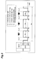
- FIG. 1 is a block diagram showing the schematic configuration of an embodiment of a biological body state assessment device according to the invention.
- a biological body state assessment device 1 of this embodiment is a device which is mounted in a vehicle to assess the biological body state of the driver of the vehicle.
- the biological body state assessment device 1 includes a face image capturing camera 2, an ECU (Electronic Control Unit) 3, and an output device 4.
- the face image capturing camera 2 images the face of the driver to generate a face image.
- the output unit 4 a device which generates a sound output, or a device which performs screen display is used.
- the ECU 3 has a CPU, a memory, such as a ROM or a RAM, an input/output circuit, and the like.
- the ECU 3 inputs the image captured by the face image capturing camera 2, performs predetermined processing, assesses the vigilance of the driver, discriminates the biological body state (vigilance state, absentminded state, drowsy state, or the like) of the driver from the vigilance, and sends the discrimination result to the output device 4.
- Fig. 2 is a flowchart showing a processing procedure which is executed by an ECU 3.
- face image data of the face image capturing camera 2 is acquired (Step S51).
- the opening/closing of the eyelids is assessed from the face image data, and the time (eye open time) for which the eyes are open is detected (Step S52).
- n denotes an n-th eye open time
- ts n denotes an n-th eye open start time
- ten denotes an n-th eye open end time.
- eye open time data (start time ts n , end time ten, eye open time to n ) is held in an eye open time storage buffer (Step S53).
- the size of the eye open time storage buffer is set so as to satisfy te n -ts 1 >tw.
- tw (see Fig. 3 ) is a unit duration during quantification of variation (described below) in the eye open time.
- the face direction left/right angle ⁇ of the driver is detected from face image data acquired in Step S51 (Step S54).
- the face direction left/right angle ⁇ is the face direction angle with respect to the vehicle front-back direction (Z-axis direction), and in this case, the right direction is positive.
- face direction left/right angle data (traveling time t n , face direction left/right angle ⁇ n ) is held in a face direction angle storage buffer (Step S55).
- the size of the face direction angle storage buffer is set so as to satisfy t n -t 1 >tw. Note that tw is a unit duration during quantification of variation (described below) in the face direction left/right angle.
- a plurality of variations in the eye open time are calculated as a statistical amount (Step S56).
- the statistical amount is a standard deviation, a dispersion, and the like, and in this case, a standard deviation is calculated.
- An arbitrary number of pieces of eye open time data previously detected may be acquired to calculate the eye open time variation Tsd.
- an arbitrary number of pieces of eye open time data stored in the eye open time storage buffer shown in Fig. 4 are extracted backward from the latest one. For example, if the latest eye open time is to n , and the number of pieces of eye open time data is 3, the eye open times to be extracted are three of to n-2 , to n-1 , and to n .
- the eye open time variation Tsd is calculated using these pieces of eye open time data by the above-described expression.
- variation in a plurality of face direction left/right angles is calculated as a statistical amount (Step S57).
- the statistical amount is a standard deviation, a dispersion, or the like, and in this case, a standard deviation is calculated.
- threshold processing is performed on the eye open time variation Tsd and the face direction left/right angle variation ⁇ sd, thereby detecting the absentminded state of the driver (Step S58). Specifically, the eye open time variation Tsd is compared with a threshold value TH1, and the face direction left/right angle variation ⁇ sd is compared with a threshold value TH2. At this time, when the eye open time variation Tsd(t) and the face direction left/right angle variation ⁇ sd(t) at the time t satisfy the following conditions, the absentminded detection flag is ON. When the following conditions are not satisfied, the absentminded detection flag is OFF. Tsd t > TH ⁇ 1 ⁇ sd t ⁇ TH ⁇ 2
- a section D TH1 is a data acquisition section for setting the threshold value TH1
- a section D TH2 is a data acquisition section for setting the threshold value TH2.
- the threshold value TH1 is set from the statistical amount of the eye open time variation from the start of driving to an arbitrary time t n .
- TH ⁇ 1 T_MEAN_SD + N ⁇ T_STDEV_SD
- the name of the driver may be stored in association with the threshold value TH1 as a database, personal authentication may be performed at the time of the start of driving, and the threshold value TH1 may be set with reference to a database corresponding to the driver. In this case, for example, it is necessary that data when the driver uses the device for the first time is held as the threshold value TH1.
- the threshold value TH2 is set from the statistical amount of the face direction left/right angle variation from the start of driving to an arbitrary time t n .
- TH ⁇ 2 ⁇ _MEAN_SD + N ⁇ ⁇ _STDEV_SD
- the name of the driver may be stored in association with the threshold value TH2 as a database, personal authentication may be performed at the time of the start of driving, and the threshold value TH2 may be set with reference to a database corresponding to the driver. In this case, for example, it is necessary that data when the driver uses the device for the first time is held as the threshold value TH2.
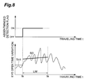
- Step S59 the possibility of the occurrence of drowsiness of the driver in the future is assessed on the basis of the absentminded detection flag and the eye open time variation using a line fitting method.
- the time at which the absentminded detection flag is changed from OFF to ON is set as the leading time t s of a line fitting section.
- the time when a line fitting section width LW has elapsed from the time t s is set as the trailing time t e of the line fitting section.
- a line approximate expression is acquired for eye open time variation data of the section of the time t s to the time t e .
- the line fitting section width LW is set to, for example, three minutes.
- the reason is that even a short sleep latency (the time until the person falls asleep) of a person (a patient who has a sleep disorder) is at the shortest about three minutes. Accordingly, it is possible to quickly assess the possibility of the occurrence of drowsiness for any driver including a healthy person.
- the time t e is the time at which eye open time variation data has been acquired, and is thus the time at which the possibility of the occurrence of drowsiness is assessed.
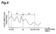
- the data processing section P is the duration section from the time (t s -LW) to the time t s
- the data processing section Q is the duration section from the time t s to the time t e .
- face direction left/right angle variation data of the data processing section P is cut, frequency analysis processing (for example, FFT processing) is performed on face direction left/right angle variation data, and as shown in Fig. 10(A) , an amplitude spectrum (frequency distribution) for a frequency component is obtained.
- a center frequency fg 1 in the frequency distribution of face direction left/right angle variation data of the data processing section P is extracted.
- face direction left/right angle variation data of the data processing section Q is cut, frequency analysis processing is performed on face direction left/right angle variation data, and a frequency distribution shown in Fig. 10(B ) is obtained.
- a center frequency fg 2 in the frequency distribution of face direction left/right angle variation data of the data processing section Q is extracted.
- Step S59 when it is assessed in Step S59 that there is the possibility of the occurrence of drowsiness in the driver, as shown in Fig. 11 , an expected drowsiness occurrence time of the driver in the future is estimated using the drowsiness occurrence possibility assessment result and the line approximate expression SD (Step S60). Specifically, first, the time t d corresponding to an intersection point of a line (expected drowsiness occurrence line) extended from the line approximate expression SD and a threshold value TH3 for drowsiness occurrence state detection is calculated. The time t d is estimated as an expected drowsiness occurrence time.
- the time difference (the required time up to the expected drowsiness occurrence time) between the time t d and the time t e is calculated.
- Step S61 As the processing results of Steps S58 to S60, whether or not the driver is in the absentminded state, whether or not there is the possibility of the occurrence of drowsiness in the driver, the required time until drowsiness occurs in the driver, and the like are sent to the output device 4 and then to the driver (Step S61).
- Fig. 12 shows an example in which the biological body state assessment device 1 is applied to actual traveling.
- the absentminded state of the driver is detected at the time Ta at which the eye open time variation is greater than the threshold value TH1, and the face direction left/right angle variation is smaller than the threshold value TH2.
- the time Tc corresponding to an intersection point of the expected drowsiness occurrence line extended from the line approximate expression SD and the threshold value TH3 is the time at which the driver becomes drowsy.
- an actual drowsiness occurrence time declared by the driver is substantially consistent with the time Tc.
- Fig. 13 shows another example in which the biological body state assessment device 1 is applied to actual traveling.
- the absentminded state of the driver is detected at the time Ta at which the eye open time variation is greater than the threshold value TH1, and the face direction left/right angle variation is smaller than the threshold value TH2.
- the time Tc corresponding to an intersection point of the expected drowsiness occurrence line extended from the line approximate expression SD and the threshold value TH3 is the time at which the driver becomes drowsy.
- an actual drowsiness occurrence time declared by the driver is substantially consistent with the time Tc.
- the face image capturing camera 2 and Step S51 (see Fig. 2 ) of the ECU 3 constitute face information acquisition means for acquiring face information of a driver.
- Steps S52, S53, and S56 (see Fig. 2 ) of the ECU 3 constitute eye open time variation calculation means for calculating variation in the eye open time of the driver on the basis of the face information of the driver.
- Steps S54, S55, and S57 constitute face direction variation calculation means for calculating variation in the face direction of the driver on the basis of the face information of the driver.
- Step S58 constitutes vigilance assessment means for assessing the vigilance of the driver on the basis of the variation in the eye open time of the driver and the variation in the face direction of the driver.
- Step S59 constitutes drowsiness occurrence assessment means for assessing whether or not there is the possibility of the occurrence of drowsiness in the driver on the basis of the increase/decrease tendency of the variation in the eye open time of the driver after the absentminded state of the driver has been detected from the vigilance of the driver assessed by the vigilance assessment means.
- Step S60 constitutes drowsiness occurrence time prediction means for predicting the time at which drowsiness occurs in the driver on the basis of a slope of an approximate expression obtained by approximating the variation in the eye open time of the driver and a threshold value set in advance when the drowsiness occurrence assessment means assesses that there is the possibility of the occurrence of drowsiness in the driver.
- the eye open time and the face direction left/right angle of the driver are detected on the basis of face image data of the face image capturing camera 2, the eye open time variation and the face direction left/right angle variation of the driver are calculated, and threshold processing is performed on the eye open time variation and the face direction left/right angle variation to detect the absentminded state of the driver, thereby accurately assessing the absentminded state which is not easily assessed. Therefore, the driver is reminded of the absentminded state before drowsiness occurs, thereby drawing the driver's attention.
- the driver Since the presence/absence of the transition from the absentminded state to the drowsiness occurrence state is assessed on the basis of the eye open time variation and the face direction left/right angle variation of the driver, when it is assessed that there is the possibility of the occurrence of drowsiness in the driver in the future, it is possible to give the driver a countermeasure (for example, chewing or the like) for suppressing drowsiness in the driver.
- a countermeasure for example, chewing or the like
- the invention provides a biological body state assessment device capable of accurately assessing the absentminded state of the driver.
- 1 biological body state assessment device
- 2 face image capturing camera (face information acquisition means)
- 3 ECU (face information acquisition means, eye open time variation calculation means, face direction variation calculation means, vigilance assessment means, drowsiness occurrence assessment means, drowsiness occurrence time prediction means).
Landscapes
- Health & Medical Sciences (AREA)
- Life Sciences & Earth Sciences (AREA)
- Physics & Mathematics (AREA)
- Engineering & Computer Science (AREA)
- Veterinary Medicine (AREA)
- Heart & Thoracic Surgery (AREA)
- Public Health (AREA)
- Biophysics (AREA)
- Pathology (AREA)
- General Health & Medical Sciences (AREA)
- Biomedical Technology (AREA)
- Animal Behavior & Ethology (AREA)
- Medical Informatics (AREA)
- Molecular Biology (AREA)
- Surgery (AREA)
- Physiology (AREA)
- General Physics & Mathematics (AREA)
- Oral & Maxillofacial Surgery (AREA)
- Dentistry (AREA)
- Psychiatry (AREA)
- Artificial Intelligence (AREA)
- Educational Technology (AREA)
- Computer Vision & Pattern Recognition (AREA)
- Ophthalmology & Optometry (AREA)
- Signal Processing (AREA)
- Business, Economics & Management (AREA)
- Emergency Management (AREA)
- Child & Adolescent Psychology (AREA)
- Developmental Disabilities (AREA)
- Optics & Photonics (AREA)
- Hospice & Palliative Care (AREA)
- Psychology (AREA)
- Social Psychology (AREA)
- Multimedia (AREA)
- Theoretical Computer Science (AREA)
- Traffic Control Systems (AREA)
- Measurement Of The Respiration, Hearing Ability, Form, And Blood Characteristics Of Living Organisms (AREA)
Abstract
Description
- The present invention relates to a biological body state assessment device which assesses a biological body state of a driver.
- As a biological body state assessment device of the related art, a biological body state assessment device described in
Patent Literature 1 is known. The biological body state assessment device described inPatent Literature 1 detects driver information, such as an eye closure time ratio reflecting vigilance, and driver information, such as a head vibration transmission rate reflecting the degree of attention concentration, calculates the average value and standard deviation of an individual driver of each piece of driver information, and assesses the drowsy state, the drowsiness-conflicting state, the concentration state, and the carelessness state of the driver on the basis of the average value, the standard deviation, and vehicle/driving environment information. - [Patent Literature 1] Japanese Unexamined Patent Application Publication No.
2007-265377 - However, in the technique of the related art, since there is no index (feature quantity) having different values between an absentminded state before drowsiness occurs and other states, it is difficult to defmitively assess an unclear biological body state, such as an absentminded state.
- An object of the invention is to provide a biological body state assessment device capable of accurately assessing an absentminded state of a driver.
- A biological body state assessment device of the invention includes face information acquisition means for acquiring face information of a driver, eye open time variation calculation means for calculating variation in the eye open time of the driver on the basis of the face information of the driver, face direction variation calculation means for calculating variation in the face direction of the driver on the basis of the face information of the driver, and vigilance assessment means for assessing the vigilance of the driver on the basis of the variation in the eye open time of the driver and the variation in the face direction of the driver.
- In the biological body state assessment device of the invention, the variation in the eye open time of the driver and the variation in the face direction of the driver are calculated on the basis of the face information of the driver. If the variation in the eye open time of the driver increases and the variation in the face direction of the driver decreases, the vigilance of the driver is lowered, and the driver tends to transit to an absentminded state. Therefore, it is possible to assess the vigilance of the driver on the basis of the variation in the eye open time of the driver and the variation in the face direction of the driver, thereby increasing the assessment accuracy of the absentminded state.
- It is preferable that the vigilance assessment means assesses that, as the variation in the face direction of the driver becomes small, the vigilance of the driver is lowered. Therefore, if the variation in the face direction of the driver becomes small, it is possible to assess that the driver tends to be in the absentminded state.
- It is preferable that the biological body state assessment device further includes drowsiness occurrence assessment means for assessing whether or not there is the possibility of the occurrence of drowsiness in the driver on the basis of the increase/decrease tendency of the variation in the eye open time of the driver after the absentminded state of the driver has been detected from the vigilance of the driver assessed by the vigilance assessment means. When the variation in the eye open time of the driver tends to decrease, the driver transits from the absentminded state to the drowsy state. In this way, it is assessed whether or not there is the possibility of the occurrence of drowsiness in the driver, thereby giving the driver a countermeasure for suppressing drowsiness.
- At this time, it is preferable that the biological body state assessment device further includes drowsiness occurrence time prediction means for predicting the time at which drowsiness occurs in the driver on the basis of a slope of an approximate expression obtained by approximating the variation in the eye open time of the driver and a threshold value set in advance when the drowsiness occurrence assessment means assesses that there is the possibility of the occurrence of drowsiness in the driver. In this case, for example, the time at which drowsiness occurs or the time until drowsiness occurs is notified to the driver, thereby recommending the driver to get rest.
- According to the invention, it is possible to accurately assess the absentminded state of the driver. Therefore, it becomes possible to discriminate the biological body state of the driver in more detail.
-
-
Fig. 1 is a block diagram showing the schematic configuration of an embodiment of a biological body state assessment device according to the invention. -
Fig. 2 is a flowchart showing a processing procedure which is executed by an ECU shown inFig. 1 . -
Fig. 3 is a diagram showing an example of variation in an eye open time within a unit duration. -
Fig. 4 is a table showing an example of an eye open time storage buffer. -
Fig. 5 is a conceptual diagram showing a face direction left/right angle of a driver. -
Fig. 6 is a table showing an example of a face direction angle storage buffer. -
Fig. 7 is a graph showing the relationship between an eye open time variation and a face direction left/right angle variation, and an absentminded detection flag. -
Fig. 8 is a graph showing an example of the relationship between an absentminded detection flag and an eye open time variation. -
Fig. 9 is a graph showing an example of a face direction left/right angle variation in which two data processing sections are set. -
Fig. 10 is a graph showing the frequency distribution of a face direction left/right angle variation in each data processing section shown inFig. 9 . -
Fig. 11 is a graph showing an example of the relationship between a drowsiness occurrence possibility assessment result and an eye open time variation. -
Fig. 12 is a graph showing the relationship between an eye open time variation and a face direction left/right angle variation in an example in which an embodiment of a biological body state assessment device according to the invention is applied to actual traveling. -
Fig. 13 is a graph showing the relationship between an eye open time variation and a face direction left/right angle variation in another example in which an embodiment of a biological body state assessment device according to the invention is applied to actual traveling. - Hereinafter, a preferred embodiment of a biological body state assessment device according to the invention will be described in detail with reference to the drawings.
-
Fig. 1 is a block diagram showing the schematic configuration of an embodiment of a biological body state assessment device according to the invention. A biological bodystate assessment device 1 of this embodiment is a device which is mounted in a vehicle to assess the biological body state of the driver of the vehicle. - The biological body
state assessment device 1 includes a faceimage capturing camera 2, an ECU (Electronic Control Unit) 3, and anoutput device 4. The faceimage capturing camera 2 images the face of the driver to generate a face image. As theoutput unit 4, a device which generates a sound output, or a device which performs screen display is used. - The
ECU 3 has a CPU, a memory, such as a ROM or a RAM, an input/output circuit, and the like. TheECU 3 inputs the image captured by the faceimage capturing camera 2, performs predetermined processing, assesses the vigilance of the driver, discriminates the biological body state (vigilance state, absentminded state, drowsy state, or the like) of the driver from the vigilance, and sends the discrimination result to theoutput device 4. -
Fig. 2 is a flowchart showing a processing procedure which is executed by anECU 3. InFig. 2 , first, face image data of the faceimage capturing camera 2 is acquired (Step S51). As shown inFig. 3 , the opening/closing of the eyelids is assessed from the face image data, and the time (eye open time) for which the eyes are open is detected (Step S52). InFig. 3 , ton denotes an n-th eye open time, tsn denotes an n-th eye open start time, and ten denotes an n-th eye open end time. - Next, as shown in
Fig. 4 , eye open time data (start time tsn, end time ten, eye open time ton) is held in an eye open time storage buffer (Step S53). The size of the eye open time storage buffer is set so as to satisfy ten-ts1>tw. Note that tw (seeFig. 3 ) is a unit duration during quantification of variation (described below) in the eye open time. - Next, as shown in
Fig. 5 , the face direction left/right angle β of the driver is detected from face image data acquired in Step S51 (Step S54). The face direction left/right angle β is the face direction angle with respect to the vehicle front-back direction (Z-axis direction), and in this case, the right direction is positive. - Next, as shown in
Fig. 6 , face direction left/right angle data (traveling time tn, face direction left/right angle βn) is held in a face direction angle storage buffer (Step S55). The size of the face direction angle storage buffer is set so as to satisfy tn-t1>tw. Note that tw is a unit duration during quantification of variation (described below) in the face direction left/right angle. - Next, a plurality of variations in the eye open time are calculated as a statistical amount (Step S56). The statistical amount is a standard deviation, a dispersion, and the like, and in this case, a standard deviation is calculated. At this time, eye open time data within the unit duration tw is acquired, and the eye open time variation (standard deviation) Tsd is calculated as follows.
eye open time within unit duration tw={to1,to2,to3,...ton}
- n : total number of extracted eye open times
- i : eye open time number
- toi : i - th eye open time data
-
to : average value of n pieces of eye open time data - An arbitrary number of pieces of eye open time data previously detected may be acquired to calculate the eye open time variation Tsd. Specifically, an arbitrary number of pieces of eye open time data stored in the eye open time storage buffer shown in
Fig. 4 are extracted backward from the latest one. For example, if the latest eye open time is ton, and the number of pieces of eye open time data is 3, the eye open times to be extracted are three of ton-2, ton-1, and ton. The eye open time variation Tsd is calculated using these pieces of eye open time data by the above-described expression. - Next, variation in a plurality of face direction left/right angles (absolute value) is calculated as a statistical amount (Step S57). The statistical amount is a standard deviation, a dispersion, or the like, and in this case, a standard deviation is calculated. At this time, face direction left/right angle (absolute value) data within the unit duration tw is acquired, and the face direction left/right angle variation (standard deviation) βsd is calculated as follows.
face direction left/right angle (absolute value) within unit duration tw={β1,β2,β3,...βn}
- n : total number of extracted face direction left/right angles (absolute value)
- i : face direction left/right angle (absolute value) data number
- βi : i - th face direction left/right angle (absolute value)
-
β : average value of n pieces of face direction left/right angle (absolute value) data - Next, as shown in
Fig. 7 , threshold processing is performed on the eye open time variation Tsd and the face direction left/right angle variation βsd, thereby detecting the absentminded state of the driver (Step S58). Specifically, the eye open time variation Tsd is compared with a threshold value TH1, and the face direction left/right angle variation βsd is compared with a threshold value TH2. At this time, when the eye open time variation Tsd(t) and the face direction left/right angle variation βsd(t) at the time t satisfy the following conditions, the absentminded detection flag is ON. When the following conditions are not satisfied, the absentminded detection flag is OFF.

- In
Fig. 7 , a section DTH1 is a data acquisition section for setting the threshold value TH1, and a section DTH2 is a data acquisition section for setting the threshold value TH2. - As a method of setting the threshold value TH1, the following method is used. That is, as the following expression, the threshold value TH1 is set from the statistical amount of the eye open time variation from the start of driving to an arbitrary time tn.

- T_MEAN_SD: average value of eye open time variation from start of driving to arbitrary time tn
- N: coefficient (for example, 3)
- T_STDEV_SD: standard deviation of eye open time variation from start of driving to arbitrary time tn
- The name of the driver may be stored in association with the threshold value TH1 as a database, personal authentication may be performed at the time of the start of driving, and the threshold value TH1 may be set with reference to a database corresponding to the driver. In this case, for example, it is necessary that data when the driver uses the device for the first time is held as the threshold value TH1.
- The value of the coefficient N in Expression (A) may change depending on an article which is put on by the driver. For example, when the driver puts glasses on, even if not absentminded, the eyes tend to get tired easily compared to the naked eyes, and the eye open time variation increases. For this reason, if the coefficient N increases (for example, N=5), erroneous detection is unlikely to occur. In this case, for example, it is assessed whether or not the driver puts the glasses on by the face
image capturing camera 2, and when the driver puts the glasses on, the threshold value TH1 is set with reference to a database for the glasses. When the driver does not put the glasses on, the threshold value TH1 is set with reference to a database for no glasses. - As a method of setting the threshold value TH2, the following method is used. That is, from the following expression, the threshold value TH2 is set from the statistical amount of the face direction left/right angle variation from the start of driving to an arbitrary time tn.

- β_MEAN_SD: average value of face direction left/right angle variation from start of driving to arbitrary time tn
- N: coefficient (for example, 2)
- β_STDEV_SD: standard deviation of face direction left/right angle variation from start of driving to arbitrary time tn
- The name of the driver may be stored in association with the threshold value TH2 as a database, personal authentication may be performed at the time of the start of driving, and the threshold value TH2 may be set with reference to a database corresponding to the driver. In this case, for example, it is necessary that data when the driver uses the device for the first time is held as the threshold value TH2.
- Next, as shown in
Fig. 8 , the possibility of the occurrence of drowsiness of the driver in the future is assessed on the basis of the absentminded detection flag and the eye open time variation using a line fitting method (Step S59). - Specifically, the time at which the absentminded detection flag is changed from OFF to ON is set as the leading time ts of a line fitting section. Next, the time when a line fitting section width LW has elapsed from the time ts is set as the trailing time te of the line fitting section. Next, a line approximate expression is acquired for eye open time variation data of the section of the time ts to the time te. As an example of an approximation method, a least-squares method is used. A line approximate expression SD is as follows.

- The following assessment is performed for the slope A of Expression (C).


When A<0 (condition 1) is satisfied, it is estimated that the driver transits from the absentminded state to the drowsy state. When A>0 is satisfied, it is estimated that the driver transits from the absentminded state to the vigilance state. - The line fitting section width LW is set to, for example, three minutes. The reason is that even a short sleep latency (the time until the person falls asleep) of a person (a patient who has a sleep disorder) is at the shortest about three minutes. Accordingly, it is possible to quickly assess the possibility of the occurrence of drowsiness for any driver including a healthy person. The time te is the time at which eye open time variation data has been acquired, and is thus the time at which the possibility of the occurrence of drowsiness is assessed.
- In Expression (C), when it is assessed that A<0 (condition 1) is satisfied, as shown in
Fig. 9 , two data processing sections P and Q are set for face direction left/right angle variation data. The data processing section P is the duration section from the time (ts-LW) to the time ts, and the data processing section Q is the duration section from the time ts to the time te. - Next, face direction left/right angle variation data of the data processing section P is cut, frequency analysis processing (for example, FFT processing) is performed on face direction left/right angle variation data, and as shown in
Fig. 10(A) , an amplitude spectrum (frequency distribution) for a frequency component is obtained. A center frequency fg1 in the frequency distribution of face direction left/right angle variation data of the data processing section P is extracted. - In the same manner as described above, face direction left/right angle variation data of the data processing section Q is cut, frequency analysis processing is performed on face direction left/right angle variation data, and a frequency distribution shown in
Fig. 10(B ) is obtained. A center frequency fg2 in the frequency distribution of face direction left/right angle variation data of the data processing section Q is extracted. - When the relationship between the center frequencies fg1 and fg2 satisfy the following expression, it is assessed that there is the possibility of the occurrence of drowsiness in the driver.

- Next, when it is assessed in Step S59 that there is the possibility of the occurrence of drowsiness in the driver, as shown in
Fig. 11 , an expected drowsiness occurrence time of the driver in the future is estimated using the drowsiness occurrence possibility assessment result and the line approximate expression SD (Step S60). Specifically, first, the time td corresponding to an intersection point of a line (expected drowsiness occurrence line) extended from the line approximate expression SD and a threshold value TH3 for drowsiness occurrence state detection is calculated. The time td is estimated as an expected drowsiness occurrence time. Since the time te becomes the time at which processing for estimating the expected drowsiness occurrence time is performed, the time difference (the required time up to the expected drowsiness occurrence time) between the time td and the time te is calculated. - Next, as the processing results of Steps S58 to S60, whether or not the driver is in the absentminded state, whether or not there is the possibility of the occurrence of drowsiness in the driver, the required time until drowsiness occurs in the driver, and the like are sent to the
output device 4 and then to the driver (Step S61). -
Fig. 12 shows an example in which the biological bodystate assessment device 1 is applied to actual traveling. InFig. 12 , the absentminded state of the driver is detected at the time Ta at which the eye open time variation is greater than the threshold value TH1, and the face direction left/right angle variation is smaller than the threshold value TH2. It is expected that the time Tc corresponding to an intersection point of the expected drowsiness occurrence line extended from the line approximate expression SD and the threshold value TH3 is the time at which the driver becomes drowsy. At this time, an actual drowsiness occurrence time declared by the driver is substantially consistent with the time Tc. -
Fig. 13 shows another example in which the biological bodystate assessment device 1 is applied to actual traveling. InFig. 13 , the absentminded state of the driver is detected at the time Ta at which the eye open time variation is greater than the threshold value TH1, and the face direction left/right angle variation is smaller than the threshold value TH2. It is expected that the time Tc corresponding to an intersection point of the expected drowsiness occurrence line extended from the line approximate expression SD and the threshold value TH3 is the time at which the driver becomes drowsy. At this time, an actual drowsiness occurrence time declared by the driver is substantially consistent with the time Tc. - In the above description, the face
image capturing camera 2 and Step S51 (seeFig. 2 ) of theECU 3 constitute face information acquisition means for acquiring face information of a driver. Steps S52, S53, and S56 (seeFig. 2 ) of theECU 3 constitute eye open time variation calculation means for calculating variation in the eye open time of the driver on the basis of the face information of the driver. Steps S54, S55, and S57 constitute face direction variation calculation means for calculating variation in the face direction of the driver on the basis of the face information of the driver. Step S58 constitutes vigilance assessment means for assessing the vigilance of the driver on the basis of the variation in the eye open time of the driver and the variation in the face direction of the driver. - Step S59 constitutes drowsiness occurrence assessment means for assessing whether or not there is the possibility of the occurrence of drowsiness in the driver on the basis of the increase/decrease tendency of the variation in the eye open time of the driver after the absentminded state of the driver has been detected from the vigilance of the driver assessed by the vigilance assessment means. Step S60 constitutes drowsiness occurrence time prediction means for predicting the time at which drowsiness occurs in the driver on the basis of a slope of an approximate expression obtained by approximating the variation in the eye open time of the driver and a threshold value set in advance when the drowsiness occurrence assessment means assesses that there is the possibility of the occurrence of drowsiness in the driver.
- As described above, in this embodiment, the eye open time and the face direction left/right angle of the driver are detected on the basis of face image data of the face
image capturing camera 2, the eye open time variation and the face direction left/right angle variation of the driver are calculated, and threshold processing is performed on the eye open time variation and the face direction left/right angle variation to detect the absentminded state of the driver, thereby accurately assessing the absentminded state which is not easily assessed. Therefore, the driver is reminded of the absentminded state before drowsiness occurs, thereby drawing the driver's attention. - Since the presence/absence of the transition from the absentminded state to the drowsiness occurrence state is assessed on the basis of the eye open time variation and the face direction left/right angle variation of the driver, when it is assessed that there is the possibility of the occurrence of drowsiness in the driver in the future, it is possible to give the driver a countermeasure (for example, chewing or the like) for suppressing drowsiness in the driver.
- When it is assessed that there is the possibility of the occurrence of drowsiness in the driver in the future, since the expected drowsiness occurrence time of the driver is estimated, the time until drowsiness occurs is informed to the driver, thereby providing reference information (for example, the selection of parking to take shelter) as a countermeasure to get rest.
- The invention provides a biological body state assessment device capable of accurately assessing the absentminded state of the driver.
- 1: biological body state assessment device, 2: face image capturing camera (face information acquisition means), 3: ECU (face information acquisition means, eye open time variation calculation means, face direction variation calculation means, vigilance assessment means, drowsiness occurrence assessment means, drowsiness occurrence time prediction means).
Claims (4)
- A biological body state assessment device comprising:face information acquisition means for acquiring face information of a driver;eye open time variation calculation means for calculating variation in the eye open time of the driver on the basis of the face information of the driver;face direction variation calculation means for calculating variation in the face direction of the driver on the basis of the face information of the driver; andvigilance assessment means for assessing the vigilance of the driver on the basis of the variation in the eye open time of the driver and the variation in the face direction of the driver.
- The biological body state assessment device according to claim 1,
wherein the vigilance assessment means assesses that, as the variation in the face direction of the driver becomes small, the vigilance of the driver is lowered. - The biological body state assessment device according to claim 1 or 2, further comprising:drowsiness occurrence assessment means for assessing whether or not there is the possibility of the occurrence of drowsiness in the driver on the basis of the increase/decrease tendency of the variation in the eye open time of the driver after the absentminded state of the driver has been detected from the vigilance of the driver assessed by the vigilance assessment means.
- The biological body state assessment device according to claim 3, further comprising:drowsiness occurrence time prediction means for predicting the time at which drowsiness occurs in the driver on the basis of a slope of an approximate expression obtained by approximating the variation in the eye open time of the driver and a threshold value set in advance when the drowsiness occurrence assessment means assesses that there is the possibility of the occurrence of drowsiness in the driver.
Applications Claiming Priority (1)
| Application Number | Priority Date | Filing Date | Title |
|---|---|---|---|
| PCT/JP2010/056177 WO2011125166A1 (en) | 2010-04-05 | 2010-04-05 | Biological body state assessment device |
Publications (3)
| Publication Number | Publication Date |
|---|---|
| EP2557549A1 true EP2557549A1 (en) | 2013-02-13 |
| EP2557549A4 EP2557549A4 (en) | 2013-11-27 |
| EP2557549B1 EP2557549B1 (en) | 2022-10-12 |
Family
ID=44762153
Family Applications (1)
| Application Number | Title | Priority Date | Filing Date |
|---|---|---|---|
| EP10849410.5A Active EP2557549B1 (en) | 2010-04-05 | 2010-04-05 | Biological body state assessment device |
Country Status (4)
| Country | Link |
|---|---|
| US (1) | US8866896B2 (en) |
| EP (1) | EP2557549B1 (en) |
| JP (1) | JP5447657B2 (en) |
| WO (1) | WO2011125166A1 (en) |
Cited By (2)
| Publication number | Priority date | Publication date | Assignee | Title |
|---|---|---|---|---|
| WO2020051781A1 (en) * | 2018-09-12 | 2020-03-19 | Beijing Didi Infinity Technology And Development Co., Ltd. | Systems and methods for drowsiness detection |
| US11861916B2 (en) | 2021-10-05 | 2024-01-02 | Yazaki Corporation | Driver alertness monitoring system |
Families Citing this family (24)
| Publication number | Priority date | Publication date | Assignee | Title |
|---|---|---|---|---|
| US9460601B2 (en) | 2009-09-20 | 2016-10-04 | Tibet MIMAR | Driver distraction and drowsiness warning and sleepiness reduction for accident avoidance |
| US9491420B2 (en) | 2009-09-20 | 2016-11-08 | Tibet MIMAR | Vehicle security with accident notification and embedded driver analytics |
| SE535765C2 (en) * | 2011-04-20 | 2012-12-11 | Scania Cv Ab | Vehicles with a safety system with prediction of driver fatigue |
| DE102013222645A1 (en) * | 2013-11-07 | 2015-05-07 | Robert Bosch Gmbh | A detection system in a vehicle for detecting the voice activity of a vehicle occupant |
| US9953230B2 (en) * | 2014-04-03 | 2018-04-24 | David Stuart Nicol | Device, system and method for vehicle safety sensing and alerting by using camera and temperature sensor |
| KR101612824B1 (en) * | 2014-11-20 | 2016-04-15 | 현대자동차주식회사 | Method and apparatus for Monitoring Driver Status using Head Mounted Display |
| KR101663387B1 (en) * | 2014-12-29 | 2016-10-07 | 뉴모텍(주) | Stator of Motor having Coil Protection Cover for Washing Machine |
| JP6638213B2 (en) * | 2015-04-28 | 2020-01-29 | いすゞ自動車株式会社 | Vehicle safe driving promotion method and vehicle safe driving promotion device |
| US10716502B2 (en) * | 2015-07-22 | 2020-07-21 | Panasonic Intellectual Property Corporation Of America | Method for predicting arousal level and arousal level prediction apparatus |
| EP3384475B1 (en) * | 2015-12-06 | 2021-12-22 | Cerence Operating Company | System and method of conversational adjustment based on user's cognitive state |
| JP6617602B2 (en) * | 2016-02-24 | 2019-12-11 | 株式会社デンソー | Maneuvering detection system and maneuvering detection method |
| JP6460349B2 (en) * | 2016-04-13 | 2019-01-30 | トヨタ自動車株式会社 | Vehicle travel control device |
| US10065651B2 (en) | 2016-05-10 | 2018-09-04 | Samsung Electronics Co., Ltd | Electronic device and method for determining a state of a driver |
| JP6701951B2 (en) * | 2016-05-20 | 2020-05-27 | アイシン精機株式会社 | Driving support device |
| JP2018025869A (en) * | 2016-08-08 | 2018-02-15 | 株式会社デンソー | Driving support system |
| JP6668999B2 (en) * | 2016-08-08 | 2020-03-18 | 株式会社デンソー | Driving support device |
| KR20180124381A (en) | 2017-05-11 | 2018-11-21 | 현대자동차주식회사 | System for detecting impaired driving and method thereof |
| CN107205036A (en) * | 2017-06-19 | 2017-09-26 | 深圳市盛路物联通讯技术有限公司 | The Internet of Things information interacting method and system of a kind of driver's eyes fatigue triggering |
| JP6915502B2 (en) * | 2017-11-09 | 2021-08-04 | トヨタ自動車株式会社 | Driver status detector |
| JP6683185B2 (en) * | 2017-11-15 | 2020-04-15 | オムロン株式会社 | Information processing device, driver monitoring system, information processing method, and information processing program |
| JP6888542B2 (en) | 2017-12-22 | 2021-06-16 | トヨタ自動車株式会社 | Drowsiness estimation device and drowsiness estimation method |
| JP7102850B2 (en) * | 2018-03-28 | 2022-07-20 | マツダ株式会社 | Driver status judgment device |
| JP2021089479A (en) * | 2019-12-02 | 2021-06-10 | 株式会社デンソー | Consciousness determination device and consciousness determination method |
| CN112561787B (en) * | 2020-12-22 | 2024-03-22 | 维沃移动通信有限公司 | Image processing method, device, electronic equipment and storage medium |
Family Cites Families (20)
| Publication number | Priority date | Publication date | Assignee | Title |
|---|---|---|---|---|
| JP2694158B2 (en) * | 1988-06-21 | 1997-12-24 | 日本ケーブル株式会社 | Cableway bending equipment |
| JPH07241283A (en) | 1994-03-04 | 1995-09-19 | Omron Corp | Awakening level determination method and awakening level determination device |
| JPH08290726A (en) | 1995-04-21 | 1996-11-05 | Mitsubishi Electric Corp | Dozing alarm device |
| US5689241A (en) * | 1995-04-24 | 1997-11-18 | Clarke, Sr.; James Russell | Sleep detection and driver alert apparatus |
| JP3455627B2 (en) | 1996-03-22 | 2003-10-14 | 日産ディーゼル工業株式会社 | Awakening degree decrease detection device for vehicles |
| JP3509839B2 (en) | 1997-03-31 | 2004-03-22 | 三菱自動車工業株式会社 | Arousal level estimation device |
| JP2002352229A (en) * | 2001-05-30 | 2002-12-06 | Mitsubishi Electric Corp | Face part detection device |
| JP3681657B2 (en) * | 2001-06-18 | 2005-08-10 | 三菱電機株式会社 | Arousal level estimation device and arousal level estimation method |
| US6927694B1 (en) * | 2001-08-20 | 2005-08-09 | Research Foundation Of The University Of Central Florida | Algorithm for monitoring head/eye motion for driver alertness with one camera |
| JP3898586B2 (en) | 2002-07-12 | 2007-03-28 | 株式会社東海理化電機製作所 | Open / close eye monitor device |
| JP4123050B2 (en) * | 2003-05-16 | 2008-07-23 | 日産自動車株式会社 | Arousal level judgment device |
| JP4622439B2 (en) * | 2004-10-13 | 2011-02-02 | 日産自動車株式会社 | Arousal level judgment device |
| JP2006151287A (en) * | 2004-11-30 | 2006-06-15 | Nissan Motor Co Ltd | Vehicle lighting device |
| JP2007265377A (en) | 2006-03-01 | 2007-10-11 | Toyota Central Res & Dev Lab Inc | Driver state determination device and driving support device |
| WO2008044119A2 (en) * | 2006-10-13 | 2008-04-17 | Toyota Jidosha Kabushiki Kaisha | On-board warning apparatus and warning method |
| JP2008204185A (en) | 2007-02-20 | 2008-09-04 | Toyota Motor Corp | Driving psychological state determination device |
| JP4727688B2 (en) * | 2008-04-23 | 2011-07-20 | トヨタ自動車株式会社 | Awakening level estimation device |
| JP5210773B2 (en) * | 2008-09-16 | 2013-06-12 | トヨタ自動車株式会社 | Sleepiness determination apparatus and program |
| WO2010092860A1 (en) | 2009-02-13 | 2010-08-19 | トヨタ自動車株式会社 | Physiological condition estimation device and vehicle control device |
| US8063786B2 (en) * | 2009-02-24 | 2011-11-22 | Panasonic Automotive Systems Company Of America Division Of Panasonic Corporation Of North America | Method of detecting drowsiness of a vehicle operator |
-
2010
- 2010-04-05 JP JP2012509215A patent/JP5447657B2/en active Active
- 2010-04-05 EP EP10849410.5A patent/EP2557549B1/en active Active
- 2010-04-05 US US13/639,208 patent/US8866896B2/en active Active
- 2010-04-05 WO PCT/JP2010/056177 patent/WO2011125166A1/en not_active Ceased
Cited By (3)
| Publication number | Priority date | Publication date | Assignee | Title |
|---|---|---|---|---|
| WO2020051781A1 (en) * | 2018-09-12 | 2020-03-19 | Beijing Didi Infinity Technology And Development Co., Ltd. | Systems and methods for drowsiness detection |
| CN111052127A (en) * | 2018-09-12 | 2020-04-21 | 北京嘀嘀无限科技发展有限公司 | System and method for fatigue detection |
| US11861916B2 (en) | 2021-10-05 | 2024-01-02 | Yazaki Corporation | Driver alertness monitoring system |
Also Published As
| Publication number | Publication date |
|---|---|
| EP2557549A4 (en) | 2013-11-27 |
| US20130021463A1 (en) | 2013-01-24 |
| JPWO2011125166A1 (en) | 2013-07-08 |
| US8866896B2 (en) | 2014-10-21 |
| JP5447657B2 (en) | 2014-03-19 |
| WO2011125166A1 (en) | 2011-10-13 |
| EP2557549B1 (en) | 2022-10-12 |
Similar Documents
| Publication | Publication Date | Title |
|---|---|---|
| US8866896B2 (en) | Biological body state assessment device including drowsiness occurrence assessment | |
| US20110313259A1 (en) | Physiological condition estimation device and vehicle control device | |
| US9286515B2 (en) | Doze detection method and apparatus thereof | |
| CN102149326B (en) | Drowsiness determining device and program | |
| EP2330582A1 (en) | Open/closed-eye judgment device, device for estimating degree of eye openness, and program | |
| CN101588757B (en) | Anti-drowsing device and anti-drowsing method | |
| US10583840B2 (en) | Methods and apparatus to monitor an activity level of a driver | |
| CN102098955B (en) | Method and device for the detection of microsleep events | |
| US10023199B2 (en) | Method and device for ascertaining a state of drowsiness of a driver | |
| CN110271561B (en) | Automatic driving warning method and device and vehicle | |
| EP2410501A1 (en) | Drowsiness assessment device and program | |
| EP3081156A1 (en) | Sleepiness detecting device | |
| KR20140147233A (en) | Apparatus and method for judging drowsiness drive using driving pattern of vehicle | |
| CN110103979B (en) | Fatigue driving alarm processing method and device and electronic equipment | |
| JP2009266100A (en) | Driver state estimation apparatus and program | |
| JP4910547B2 (en) | Sleepiness determination apparatus and sleepiness determination program | |
| CN104616436B (en) | Fatigue driving judgment system and method thereof | |
| US11260874B2 (en) | Driver assistance device that can be mounted on a vehicle | |
| JP2008301957A (en) | Psychological state estimation device | |
| JP2008099884A (en) | State estimation device | |
| JP2010184067A (en) | Biological state prediction device | |
| JP2018130342A (en) | Arousal level estimation device, arousal level estimation method, and arousal level estimation system | |
| US9820687B2 (en) | Method for determining drowsiness | |
| JP6199647B2 (en) | Driver state determination device, vehicle control device, and driver state determination method | |
| JP2008073335A (en) | Arousal reduction detection device and arousal reduction detection program |
Legal Events
| Date | Code | Title | Description |
|---|---|---|---|
| PUAI | Public reference made under article 153(3) epc to a published international application that has entered the european phase |
Free format text: ORIGINAL CODE: 0009012 |
|
| 17P | Request for examination filed |
Effective date: 20121016 |
|
| AK | Designated contracting states |
Kind code of ref document: A1 Designated state(s): AT BE BG CH CY CZ DE DK EE ES FI FR GB GR HR HU IE IS IT LI LT LU LV MC MK MT NL NO PL PT RO SE SI SK SM TR |
|
| RAP1 | Party data changed (applicant data changed or rights of an application transferred) |
Owner name: TOYOTA JIDOSHA KABUSHIKI KAISHA |
|
| DAX | Request for extension of the european patent (deleted) | ||
| A4 | Supplementary search report drawn up and despatched |
Effective date: 20131029 |
|
| RIC1 | Information provided on ipc code assigned before grant |
Ipc: B60K 28/06 20060101ALN20131022BHEP Ipc: B60R 11/04 20060101ALI20131022BHEP Ipc: B60R 21/00 20060101ALI20131022BHEP Ipc: G02B 27/00 20060101ALN20131022BHEP Ipc: A61B 5/00 20060101ALI20131022BHEP Ipc: A61B 5/11 20060101ALI20131022BHEP Ipc: A61B 5/18 20060101ALI20131022BHEP Ipc: G08G 1/16 20060101AFI20131022BHEP |
|
| STAA | Information on the status of an ep patent application or granted ep patent |
Free format text: STATUS: EXAMINATION IS IN PROGRESS |
|
| 17Q | First examination report despatched |
Effective date: 20191120 |
|
| RIC1 | Information provided on ipc code assigned before grant |
Ipc: G02B 27/00 20060101ALN20220203BHEP Ipc: B60K 28/06 20060101ALN20220203BHEP Ipc: G06V 20/59 20220101ALI20220203BHEP Ipc: G02B 27/01 20060101ALI20220203BHEP Ipc: G08B 21/06 20060101ALI20220203BHEP Ipc: A61B 5/11 20060101ALI20220203BHEP Ipc: A61B 5/00 20060101ALI20220203BHEP Ipc: B60R 21/00 20060101ALI20220203BHEP Ipc: B60R 11/04 20060101ALI20220203BHEP Ipc: A61B 5/18 20060101ALI20220203BHEP Ipc: G08G 1/16 20060101AFI20220203BHEP |
|
| GRAP | Despatch of communication of intention to grant a patent |
Free format text: ORIGINAL CODE: EPIDOSNIGR1 |
|
| STAA | Information on the status of an ep patent application or granted ep patent |
Free format text: STATUS: GRANT OF PATENT IS INTENDED |
|
| INTG | Intention to grant announced |
Effective date: 20220330 |
|
| GRAJ | Information related to disapproval of communication of intention to grant by the applicant or resumption of examination proceedings by the epo deleted |
Free format text: ORIGINAL CODE: EPIDOSDIGR1 |
|
| STAA | Information on the status of an ep patent application or granted ep patent |
Free format text: STATUS: EXAMINATION IS IN PROGRESS |
|
| INTC | Intention to grant announced (deleted) | ||
| RIC1 | Information provided on ipc code assigned before grant |
Ipc: G02B 27/00 20060101ALN20220621BHEP Ipc: B60K 28/06 20060101ALN20220621BHEP Ipc: G06V 20/59 20220101ALI20220621BHEP Ipc: G02B 27/01 20060101ALI20220621BHEP Ipc: G08B 21/06 20060101ALI20220621BHEP Ipc: A61B 5/11 20060101ALI20220621BHEP Ipc: A61B 5/00 20060101ALI20220621BHEP Ipc: B60R 21/00 20060101ALI20220621BHEP Ipc: B60R 11/04 20060101ALI20220621BHEP Ipc: A61B 5/18 20060101ALI20220621BHEP Ipc: G08G 1/16 20060101AFI20220621BHEP |
|
| GRAP | Despatch of communication of intention to grant a patent |
Free format text: ORIGINAL CODE: EPIDOSNIGR1 |
|
| STAA | Information on the status of an ep patent application or granted ep patent |
Free format text: STATUS: GRANT OF PATENT IS INTENDED |
|
| RIC1 | Information provided on ipc code assigned before grant |
Ipc: G02B 27/00 20060101ALN20220708BHEP Ipc: B60K 28/06 20060101ALN20220708BHEP Ipc: G06V 20/59 20220101ALI20220708BHEP Ipc: G02B 27/01 20060101ALI20220708BHEP Ipc: G08B 21/06 20060101ALI20220708BHEP Ipc: A61B 5/11 20060101ALI20220708BHEP Ipc: A61B 5/00 20060101ALI20220708BHEP Ipc: B60R 21/00 20060101ALI20220708BHEP Ipc: B60R 11/04 20060101ALI20220708BHEP Ipc: A61B 5/18 20060101ALI20220708BHEP Ipc: G08G 1/16 20060101AFI20220708BHEP |
|
| INTG | Intention to grant announced |
Effective date: 20220804 |
|
| GRAS | Grant fee paid |
Free format text: ORIGINAL CODE: EPIDOSNIGR3 |
|
| GRAA | (expected) grant |
Free format text: ORIGINAL CODE: 0009210 |
|
| STAA | Information on the status of an ep patent application or granted ep patent |
Free format text: STATUS: THE PATENT HAS BEEN GRANTED |
|
| AK | Designated contracting states |
Kind code of ref document: B1 Designated state(s): AT BE BG CH CY CZ DE DK EE ES FI FR GB GR HR HU IE IS IT LI LT LU LV MC MK MT NL NO PL PT RO SE SI SK SM TR |
|
| REG | Reference to a national code |
Ref country code: GB Ref legal event code: FG4D |
|
| REG | Reference to a national code |
Ref country code: CH Ref legal event code: EP |
|
| REG | Reference to a national code |
Ref country code: DE Ref legal event code: R096 Ref document number: 602010068519 Country of ref document: DE |
|
| REG | Reference to a national code |
Ref country code: IE Ref legal event code: FG4D |
|
| REG | Reference to a national code |
Ref country code: AT Ref legal event code: REF Ref document number: 1524648 Country of ref document: AT Kind code of ref document: T Effective date: 20221115 |
|
| REG | Reference to a national code |
Ref country code: DE Ref legal event code: R081 Ref document number: 602010068519 Country of ref document: DE Owner name: TOYOTA JIDOSHA KABUSHIKI KAISHA, TOYOTA-SHI, JP Free format text: FORMER OWNER: TOYOTA JIDOSHA KABUSHIKI KAISHA, TOYOTA-SHI, AICHI-KEN, JP |
|
| REG | Reference to a national code |
Ref country code: LT Ref legal event code: MG9D |
|
| REG | Reference to a national code |
Ref country code: AT Ref legal event code: MK05 Ref document number: 1524648 Country of ref document: AT Kind code of ref document: T Effective date: 20221012 |
|
| PG25 | Lapsed in a contracting state [announced via postgrant information from national office to epo] |
Ref country code: NL Free format text: LAPSE BECAUSE OF FAILURE TO SUBMIT A TRANSLATION OF THE DESCRIPTION OR TO PAY THE FEE WITHIN THE PRESCRIBED TIME-LIMIT Effective date: 20221012 |
|
| PG25 | Lapsed in a contracting state [announced via postgrant information from national office to epo] |
Ref country code: SE Free format text: LAPSE BECAUSE OF FAILURE TO SUBMIT A TRANSLATION OF THE DESCRIPTION OR TO PAY THE FEE WITHIN THE PRESCRIBED TIME-LIMIT Effective date: 20221012 Ref country code: PT Free format text: LAPSE BECAUSE OF FAILURE TO SUBMIT A TRANSLATION OF THE DESCRIPTION OR TO PAY THE FEE WITHIN THE PRESCRIBED TIME-LIMIT Effective date: 20230213 Ref country code: NO Free format text: LAPSE BECAUSE OF FAILURE TO SUBMIT A TRANSLATION OF THE DESCRIPTION OR TO PAY THE FEE WITHIN THE PRESCRIBED TIME-LIMIT Effective date: 20230112 Ref country code: LT Free format text: LAPSE BECAUSE OF FAILURE TO SUBMIT A TRANSLATION OF THE DESCRIPTION OR TO PAY THE FEE WITHIN THE PRESCRIBED TIME-LIMIT Effective date: 20221012 Ref country code: FI Free format text: LAPSE BECAUSE OF FAILURE TO SUBMIT A TRANSLATION OF THE DESCRIPTION OR TO PAY THE FEE WITHIN THE PRESCRIBED TIME-LIMIT Effective date: 20221012 Ref country code: ES Free format text: LAPSE BECAUSE OF FAILURE TO SUBMIT A TRANSLATION OF THE DESCRIPTION OR TO PAY THE FEE WITHIN THE PRESCRIBED TIME-LIMIT Effective date: 20221012 Ref country code: AT Free format text: LAPSE BECAUSE OF FAILURE TO SUBMIT A TRANSLATION OF THE DESCRIPTION OR TO PAY THE FEE WITHIN THE PRESCRIBED TIME-LIMIT Effective date: 20221012 |
|
| PG25 | Lapsed in a contracting state [announced via postgrant information from national office to epo] |
Ref country code: PL Free format text: LAPSE BECAUSE OF FAILURE TO SUBMIT A TRANSLATION OF THE DESCRIPTION OR TO PAY THE FEE WITHIN THE PRESCRIBED TIME-LIMIT Effective date: 20221012 Ref country code: LV Free format text: LAPSE BECAUSE OF FAILURE TO SUBMIT A TRANSLATION OF THE DESCRIPTION OR TO PAY THE FEE WITHIN THE PRESCRIBED TIME-LIMIT Effective date: 20221012 Ref country code: IS Free format text: LAPSE BECAUSE OF FAILURE TO SUBMIT A TRANSLATION OF THE DESCRIPTION OR TO PAY THE FEE WITHIN THE PRESCRIBED TIME-LIMIT Effective date: 20230212 Ref country code: HR Free format text: LAPSE BECAUSE OF FAILURE TO SUBMIT A TRANSLATION OF THE DESCRIPTION OR TO PAY THE FEE WITHIN THE PRESCRIBED TIME-LIMIT Effective date: 20221012 Ref country code: GR Free format text: LAPSE BECAUSE OF FAILURE TO SUBMIT A TRANSLATION OF THE DESCRIPTION OR TO PAY THE FEE WITHIN THE PRESCRIBED TIME-LIMIT Effective date: 20230113 |
|
| P01 | Opt-out of the competence of the unified patent court (upc) registered |
Effective date: 20230427 |
|
| REG | Reference to a national code |
Ref country code: DE Ref legal event code: R084 Ref document number: 602010068519 Country of ref document: DE |
|
| REG | Reference to a national code |
Ref country code: DE Ref legal event code: R097 Ref document number: 602010068519 Country of ref document: DE |
|
| PG25 | Lapsed in a contracting state [announced via postgrant information from national office to epo] |
Ref country code: SM Free format text: LAPSE BECAUSE OF FAILURE TO SUBMIT A TRANSLATION OF THE DESCRIPTION OR TO PAY THE FEE WITHIN THE PRESCRIBED TIME-LIMIT Effective date: 20221012 Ref country code: RO Free format text: LAPSE BECAUSE OF FAILURE TO SUBMIT A TRANSLATION OF THE DESCRIPTION OR TO PAY THE FEE WITHIN THE PRESCRIBED TIME-LIMIT Effective date: 20221012 Ref country code: EE Free format text: LAPSE BECAUSE OF FAILURE TO SUBMIT A TRANSLATION OF THE DESCRIPTION OR TO PAY THE FEE WITHIN THE PRESCRIBED TIME-LIMIT Effective date: 20221012 Ref country code: DK Free format text: LAPSE BECAUSE OF FAILURE TO SUBMIT A TRANSLATION OF THE DESCRIPTION OR TO PAY THE FEE WITHIN THE PRESCRIBED TIME-LIMIT Effective date: 20221012 Ref country code: CZ Free format text: LAPSE BECAUSE OF FAILURE TO SUBMIT A TRANSLATION OF THE DESCRIPTION OR TO PAY THE FEE WITHIN THE PRESCRIBED TIME-LIMIT Effective date: 20221012 |
|
| PLBE | No opposition filed within time limit |
Free format text: ORIGINAL CODE: 0009261 |
|
| STAA | Information on the status of an ep patent application or granted ep patent |
Free format text: STATUS: NO OPPOSITION FILED WITHIN TIME LIMIT |
|
| PG25 | Lapsed in a contracting state [announced via postgrant information from national office to epo] |
Ref country code: SK Free format text: LAPSE BECAUSE OF FAILURE TO SUBMIT A TRANSLATION OF THE DESCRIPTION OR TO PAY THE FEE WITHIN THE PRESCRIBED TIME-LIMIT Effective date: 20221012 |
|
| 26N | No opposition filed |
Effective date: 20230713 |
|
| PG25 | Lapsed in a contracting state [announced via postgrant information from national office to epo] |
Ref country code: SI Free format text: LAPSE BECAUSE OF FAILURE TO SUBMIT A TRANSLATION OF THE DESCRIPTION OR TO PAY THE FEE WITHIN THE PRESCRIBED TIME-LIMIT Effective date: 20221012 |
|
| REG | Reference to a national code |
Ref country code: CH Ref legal event code: PL |
|
| GBPC | Gb: european patent ceased through non-payment of renewal fee |
Effective date: 20230405 |
|
| PG25 | Lapsed in a contracting state [announced via postgrant information from national office to epo] |
Ref country code: LU Free format text: LAPSE BECAUSE OF NON-PAYMENT OF DUE FEES Effective date: 20230405 |
|
| REG | Reference to a national code |
Ref country code: BE Ref legal event code: MM Effective date: 20230430 |
|
| PG25 | Lapsed in a contracting state [announced via postgrant information from national office to epo] |
Ref country code: MC Free format text: LAPSE BECAUSE OF FAILURE TO SUBMIT A TRANSLATION OF THE DESCRIPTION OR TO PAY THE FEE WITHIN THE PRESCRIBED TIME-LIMIT Effective date: 20221012 |
|
| PG25 | Lapsed in a contracting state [announced via postgrant information from national office to epo] |
Ref country code: GB Free format text: LAPSE BECAUSE OF NON-PAYMENT OF DUE FEES Effective date: 20230405 |
|
| PG25 | Lapsed in a contracting state [announced via postgrant information from national office to epo] |
Ref country code: MC Free format text: LAPSE BECAUSE OF FAILURE TO SUBMIT A TRANSLATION OF THE DESCRIPTION OR TO PAY THE FEE WITHIN THE PRESCRIBED TIME-LIMIT Effective date: 20221012 Ref country code: LI Free format text: LAPSE BECAUSE OF NON-PAYMENT OF DUE FEES Effective date: 20230430 Ref country code: GB Free format text: LAPSE BECAUSE OF NON-PAYMENT OF DUE FEES Effective date: 20230405 Ref country code: FR Free format text: LAPSE BECAUSE OF NON-PAYMENT OF DUE FEES Effective date: 20230430 Ref country code: CH Free format text: LAPSE BECAUSE OF NON-PAYMENT OF DUE FEES Effective date: 20230430 |
|
| REG | Reference to a national code |
Ref country code: IE Ref legal event code: MM4A |
|
| PG25 | Lapsed in a contracting state [announced via postgrant information from national office to epo] |
Ref country code: BE Free format text: LAPSE BECAUSE OF NON-PAYMENT OF DUE FEES Effective date: 20230430 |
|
| PG25 | Lapsed in a contracting state [announced via postgrant information from national office to epo] |
Ref country code: IE Free format text: LAPSE BECAUSE OF NON-PAYMENT OF DUE FEES Effective date: 20230405 |
|
| PG25 | Lapsed in a contracting state [announced via postgrant information from national office to epo] |
Ref country code: IE Free format text: LAPSE BECAUSE OF NON-PAYMENT OF DUE FEES Effective date: 20230405 |
|
| PG25 | Lapsed in a contracting state [announced via postgrant information from national office to epo] |
Ref country code: IT Free format text: LAPSE BECAUSE OF FAILURE TO SUBMIT A TRANSLATION OF THE DESCRIPTION OR TO PAY THE FEE WITHIN THE PRESCRIBED TIME-LIMIT Effective date: 20221012 |
|
| PG25 | Lapsed in a contracting state [announced via postgrant information from national office to epo] |
Ref country code: BG Free format text: LAPSE BECAUSE OF FAILURE TO SUBMIT A TRANSLATION OF THE DESCRIPTION OR TO PAY THE FEE WITHIN THE PRESCRIBED TIME-LIMIT Effective date: 20221012 |
|
| PG25 | Lapsed in a contracting state [announced via postgrant information from national office to epo] |
Ref country code: BG Free format text: LAPSE BECAUSE OF FAILURE TO SUBMIT A TRANSLATION OF THE DESCRIPTION OR TO PAY THE FEE WITHIN THE PRESCRIBED TIME-LIMIT Effective date: 20221012 |
|
| PGFP | Annual fee paid to national office [announced via postgrant information from national office to epo] |
Ref country code: DE Payment date: 20250305 Year of fee payment: 16 |
|
| PG25 | Lapsed in a contracting state [announced via postgrant information from national office to epo] |
Ref country code: CY Free format text: LAPSE BECAUSE OF FAILURE TO SUBMIT A TRANSLATION OF THE DESCRIPTION OR TO PAY THE FEE WITHIN THE PRESCRIBED TIME-LIMIT; INVALID AB INITIO Effective date: 20100405 |
|
| PG25 | Lapsed in a contracting state [announced via postgrant information from national office to epo] |
Ref country code: HU Free format text: LAPSE BECAUSE OF FAILURE TO SUBMIT A TRANSLATION OF THE DESCRIPTION OR TO PAY THE FEE WITHIN THE PRESCRIBED TIME-LIMIT; INVALID AB INITIO Effective date: 20100405 |
|
| PG25 | Lapsed in a contracting state [announced via postgrant information from national office to epo] |
Ref country code: TR Free format text: LAPSE BECAUSE OF FAILURE TO SUBMIT A TRANSLATION OF THE DESCRIPTION OR TO PAY THE FEE WITHIN THE PRESCRIBED TIME-LIMIT Effective date: 20221012 |