EP2557371A1 - Wall hanging air conditioner - Google Patents
Wall hanging air conditioner Download PDFInfo
- Publication number
- EP2557371A1 EP2557371A1 EP11765051A EP11765051A EP2557371A1 EP 2557371 A1 EP2557371 A1 EP 2557371A1 EP 11765051 A EP11765051 A EP 11765051A EP 11765051 A EP11765051 A EP 11765051A EP 2557371 A1 EP2557371 A1 EP 2557371A1
- Authority
- EP
- European Patent Office
- Prior art keywords
- blade
- swing
- air conditioner
- wall mounted
- base
- Prior art date
- Legal status (The legal status is an assumption and is not a legal conclusion. Google has not performed a legal analysis and makes no representation as to the accuracy of the status listed.)
- Granted
Links
Images
Classifications
-
- F—MECHANICAL ENGINEERING; LIGHTING; HEATING; WEAPONS; BLASTING
- F24—HEATING; RANGES; VENTILATING
- F24F—AIR-CONDITIONING; AIR-HUMIDIFICATION; VENTILATION; USE OF AIR CURRENTS FOR SCREENING
- F24F1/00—Room units for air-conditioning, e.g. separate or self-contained units or units receiving primary air from a central station
- F24F1/0007—Indoor units, e.g. fan coil units
- F24F1/0011—Indoor units, e.g. fan coil units characterised by air outlets
-
- F—MECHANICAL ENGINEERING; LIGHTING; HEATING; WEAPONS; BLASTING
- F24—HEATING; RANGES; VENTILATING
- F24F—AIR-CONDITIONING; AIR-HUMIDIFICATION; VENTILATION; USE OF AIR CURRENTS FOR SCREENING
- F24F1/00—Room units for air-conditioning, e.g. separate or self-contained units or units receiving primary air from a central station
- F24F1/0007—Indoor units, e.g. fan coil units
- F24F1/0043—Indoor units, e.g. fan coil units characterised by mounting arrangements
- F24F1/0057—Indoor units, e.g. fan coil units characterised by mounting arrangements mounted in or on a wall
-
- F—MECHANICAL ENGINEERING; LIGHTING; HEATING; WEAPONS; BLASTING
- F24—HEATING; RANGES; VENTILATING
- F24F—AIR-CONDITIONING; AIR-HUMIDIFICATION; VENTILATION; USE OF AIR CURRENTS FOR SCREENING
- F24F13/00—Details common to, or for air-conditioning, air-humidification, ventilation or use of air currents for screening
- F24F13/08—Air-flow control members, e.g. louvres, grilles, flaps or guide plates
- F24F13/10—Air-flow control members, e.g. louvres, grilles, flaps or guide plates movable, e.g. dampers
- F24F13/14—Air-flow control members, e.g. louvres, grilles, flaps or guide plates movable, e.g. dampers built up of tilting members, e.g. louvre
- F24F13/1426—Air-flow control members, e.g. louvres, grilles, flaps or guide plates movable, e.g. dampers built up of tilting members, e.g. louvre characterised by actuating means
-
- F—MECHANICAL ENGINEERING; LIGHTING; HEATING; WEAPONS; BLASTING
- F24—HEATING; RANGES; VENTILATING
- F24F—AIR-CONDITIONING; AIR-HUMIDIFICATION; VENTILATION; USE OF AIR CURRENTS FOR SCREENING
- F24F13/00—Details common to, or for air-conditioning, air-humidification, ventilation or use of air currents for screening
- F24F13/08—Air-flow control members, e.g. louvres, grilles, flaps or guide plates
- F24F13/10—Air-flow control members, e.g. louvres, grilles, flaps or guide plates movable, e.g. dampers
- F24F13/14—Air-flow control members, e.g. louvres, grilles, flaps or guide plates movable, e.g. dampers built up of tilting members, e.g. louvre
- F24F13/15—Air-flow control members, e.g. louvres, grilles, flaps or guide plates movable, e.g. dampers built up of tilting members, e.g. louvre with parallel simultaneously tiltable lamellae
Definitions
- the present application relates to the field of indoor air conditioners, in particular, to a wall mounted air conditioner.
- Swing blades of the wall mounted air conditioner in the prior art are generally mounted at an upper portion of the air outlet. Since the air outlet of the air conditioner has a larger air output at the lower portion than at the upper portion, the adjustment of the air discharging angle of the air conditioner and the comfort level would be limited to some extent in the case of mounting the swing blades at the upper portion of the air outlet. Thus, the air blowing out of the air conditioner can not flow properly indoors, and the comfortable feeling of the people in rooms can be reduced.
- An object of the present application is to provide a wall mounted air conditioner which can solve some technical problems such as the limited air discharging angle of the air conditioner and the low comfort level.
- a wall mounted air conditioner which includes: a panel provided with an air outlet, and a swing blade mechanism mounted at a lower portion of the air outlet.
- the swing blade mechanism may includes: a base mounted on an air outlet seat of the lower portion of the air outlet; a plurality of swing blades provided on the base in sequence; and a transmission mechanism connected transmittedly to a drive output end of a swing motor of the wall mounted air conditioner and connected to each of the plurality of swing blades.
- each of the plurality of the swing blades may includes: a blade body connected to the transmission mechanism; a blade seat provided at a bottom portion of the blade body and fixedly connected to the base; and an elastic connecting part connecting between the blade body and the blade seat.
- the elastic connecting part may be of an elongated shape, and an upper end of the elastic connecting part may be connected to an inner edge of the blade body.
- the transmission mechanism may be a connecting rod.
- the connecting rod may be provided with a plurality of grooves, and a blade notch may be provided at an outer side of each of the blade bodies.
- the blade notch of each of the blade bodies may be fitted with the corresponding groove of the connecting rod.
- the connecting rod may be provided with a plurality of ring-shaped friction portions, and a blade notch may be provided at one side of each of the blade bodies.
- the blade notch of each of the blade bodies is closely fitted with the corresponding friction portion of the connecting rod.
- the blade notch may be provided at a middle portion of an outer edge of the corresponding blade body.
- the swing blade mechanism may include a manual adjusting device.
- the manual adjusting device may include: a rotary shaft rotatably provided on the base and including a manual force exerting portion and a pinion portion; and a rack portion provided on the connecting rod and engaged with the pinion portion.
- the manual force exerting portion is a polyhedral prism portion provided at a middle portion of the rotary shaft, and the pinion portion is provided at an upper end of the rotary shaft.
- the base of the swing blade mechanism may includes: a sinking step portion at least provided at a longitudinal edge portion of the base; a recess portion which may be provided therein with a counter bore extending through the base; and protrusions fitted with an edge portion of the sinking step portion and the counter bore of the recess portion may be provided on the air outlet seat of the air conditioner.
- the present application can obtain the following advantageous technical effects.
- the swing blade mechanism is provided at the lower portion of the air outlet, which may efficiently guide the direction of the air, improve the swing angle, and increase the comfortable feeling of the people.
- the base, the transmission mechanism and the plurality of swing blades are combined to form the swing blade mechanism, which not only can ensure the flexible swing of the blade bodies, but also can facilitate detaching and mounting of the mechanism.
- the components of the swing blade mechanism are failure or need to be cleaned, these components can be detached quickly and easily, thereby increasing the operating efficiency.
- the swing angle of the swing blades can be adjusted manually, thereby further improving the flexibility of the swing blade mechanism.
- the locating counter bores or locating holes provided in the rectangular recesses are fitted with the locating protrusions or locating pins, so that the swing blade mechanism is mounted on the seat of the lower portion of the air outlet, thereby increasing the detaching and mounting efficiency of the swing blade mechanism.
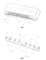
- Figure 1 is a structural schematic view of the assembly of a preferred embodiment of the present application.
- Figure 2 is a structural schematic view of a swing blade mechanism of a preferred embodiment of the present application
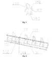
- Figure 3 is a structural schematic view of one swing blade of a preferred embodiment of the present application.
- Figure 4 is an enlarged structural schematic view of part I in figure 1 indicating a manual rotary device.
- the wall mounted air conditioner of the present application includes a panel 1.
- An air outlet 10 is provided in the panel 1, and a swing blade mechanism 3 is provided at a lower portion 102 of the air outlet.
- the swing device for is generally mounted at the upper portion 101 of the air outlet 10.
- the air outlet has a larger air output at the lower portion 102 than at the upper portion, it is difficult for the swing device located at the upper portion of the air outlet 10 to perform an effective sweep for the air outgoing from the lower portion 102 of the air outlet, and the air discharging angle of the air conditioner is also limited.
- the swing blade mechanism 3 is provided at the lower portion 102 of the air outlet, which can efficiently change the air discharging direction, and can improve the air discharging angle under a relatively large air force, thereby increasing the flowing range of the air discharged from the air conditioner indoors and increase the comfortable feeling of the people.
- the swing blade mechanism 3 may include a base 31, a transmission mechanism 33, and a plurality of swing blades 35 connected in a transmission manner to the transmission mechanism 33.
- An end of the transmission mechanism 33 is connected in a transmission manner to a drive output end of a swing motor of the wall mounted air conditioner.
- the swing blades 35 can be driven to swing left or right under the drive of the swing motor.
- the plurality of swing blades 35 may be provided on the base 31 in sequence and at an equal interval.
- each swing blade 35 may include a blade body 351, a blade seat 353, and an elastic connecting part 355 connecting the blade body 351 and the blade seat 353.
- the blade seat 353 is fixedly connected to an air outlet seat of the lower portion 102 of the air outlet 10.
- the elastic connecting part 355 may be of an elongated shape, and an upper end of the elastic connecting part 355 may be connected to an inner edge of the blade body 351.
- the upper end of the elastic connecting part 355 may be connected to an upper end of the inner edge of the blade body 351, to efficiently reduce the connection portion between the elastic connecting part 355 and the blade body 351 and increase the swing flexibility of the blade body 351.
- the blade body 351 may be fixedly connected to the base 31 via the elastic connecting part 355 and the blade seat 353.
- the elastic connecting part 355 and the blade body 351 may be made into one piece, or be formed separately.
- the elastic connecting part 355 and the blade seat 353 may be made into one piece, or be formed separately.
- the blade seat 353 may be fixedly connected to the base 31 in an inserted coupling manner, and accordingly, the base 31 may be provided with the corresponding number of grooves.
- the blade body 351 may be made of an elastic material that can be bent, such that the blade body 351 can be driven by the transmission mechanism 33 to swing left of right under the elastic force.
- each blade body 351 may be connected to the transmission mechanism 33 in a snap-fit coupling manner.
- the transmission mechanism 33 may be a connecting rod, and each swing blade 35 may be connected to the connecting rod in a snap-fit coupling manner.
- the connecting rod may be provided with a plurality of grooves, and each blade body 351 may be correspondingly provided at a side thereof with a blade notch 352, such that the blade notch 352 of each blade body 351 is fitted with corresponding groove of the connecting rod.
- the connecting rod may also be provided with a plurality of ring-shaped friction portions, and the blade notch 352 of each blade body 351 may be closely engaged with the corresponding friction portion of the connecting rod, such that the blade body 351 may be driven by the connecting rod to swing left or right under the friction force.
- the blade notch 352 may be provided at a middle portion of an outer edge of each blade body 351 and is located at the opposite side of the elastic connecting part 355.
- the connecting rod When the swing blade mechanism 3 is operated, the connecting rod is rotated under the drive of the drive output end of the swing motor, and thus drives the blade body 351 of each swing blade 35 to swing left or right so as to perform the air sweep, thereby achieving the adjustment of a relatively large air discharging angle.
- the swing blade mechanism 3 may further includes a manual adjusting device.
- the manual adjusting device includes a rotary shaft 32 and a rack portion.
- the rotary shaft 32 is rotatably provided on the base 31, and includes a manual force exerting portion 321 and a pinion portion 322.
- the rack portion is provided on the connecting rod and engages with the pinion portion 322.
- the manual force exerting portion 321 may be a polyhedral prism portion provided at a middle portion of the rotary shaft 32, and the pinion portion 322 may be provided at an upper end of the rotary shaft 32.
- the polyhedral prism portion may be rotated manually such that the pinion portion 322 is rotated accordingly, so as to drive the connecting rod to move left or right through the engagement between the pinion of an upper end of the pinion portion and the rack of the connecting rod, thereby achieving the leftward or rightward swing of the swing blade 35.
- the manual force exerting portion 321 may also be configured as a handle mounted on the rotary shaft 32.
- the rotary shaft 32 may be rotated at an angle by operating the handle, such that the connecting rod moves by a distance in a longitudinal direction, thereby achieving the adjustment of the air direction via the swing blades 35 connected to the connecting rod.
- the swing blade mechanism 3 may further include a sinking step portion 37 which is at least provided at a longitudinal edge portion of the base 31.
- a lower side of the sinking step portion 37 may be detachably fixed on the air outlet seat of the lower portion of the air outlet 10.
- the sinking step portion 37 may be of a semicircular shape or a rectangular shape, or any other shape adapted to snap fit with the air outlet seat.
- the sinking step portion is of a rectangular shape.
- a top surface of the base 31 may be provided with several rectangular recesses 38.
- a rectangular recess 38 may be provided at each end portion as well as a middle position of the base 31.
- An edge counter bore 382 extending through the base 31 may be provided in each of the rectangular recesses 38 at the two end portions of the base 31, and protrusions fitted with the edge counter bores 382 may be provided at corresponding positions of the air outlet seat of the lower portion 102 of the air outlet 10.
- Two middle counter bores 381 may be provided in the rectangular recess 38 at the middle position of the base 31. Accordingly, two protrusions corresponding to the two middle counter bores 381 may be provided at corresponding positions of the air outlet seat of the lower portion 102 of the air outlet 10.
- the rectangular recesses 38 may also be of a circular shape or any other suitable shape.
- the protrusions on the air outlet seat of the lower portion 102 of the air outlet 10 may be inserted into the edge counter bores 382, thereby achieving the reliable mounting of the swing blade mechanism 3.
- the swing blade mechanism 3 may be easily detached from the wall mounted air conditioner, which is convenient and flexible.
Landscapes
- Engineering & Computer Science (AREA)
- Chemical & Material Sciences (AREA)
- Combustion & Propulsion (AREA)
- Mechanical Engineering (AREA)
- General Engineering & Computer Science (AREA)
- Air-Flow Control Members (AREA)
Abstract
Description
- The present application claims the benefit of priority to the Chinese patent application No.
201020158149.X - The present application relates to the field of indoor air conditioners, in particular, to a wall mounted air conditioner.
- Swing blades of the wall mounted air conditioner in the prior art are generally mounted at an upper portion of the air outlet. Since the air outlet of the air conditioner has a larger air output at the lower portion than at the upper portion, the adjustment of the air discharging angle of the air conditioner and the comfort level would be limited to some extent in the case of mounting the swing blades at the upper portion of the air outlet. Thus, the air blowing out of the air conditioner can not flow properly indoors, and the comfortable feeling of the people in rooms can be reduced.
- An object of the present application is to provide a wall mounted air conditioner which can solve some technical problems such as the limited air discharging angle of the air conditioner and the low comfort level.
- In view of this, the present application provides a wall mounted air conditioner which includes: a panel provided with an air outlet, and a swing blade mechanism mounted at a lower portion of the air outlet.
- Further, the swing blade mechanism may includes: a base mounted on an air outlet seat of the lower portion of the air outlet; a plurality of swing blades provided on the base in sequence; and a transmission mechanism connected transmittedly to a drive output end of a swing motor of the wall mounted air conditioner and connected to each of the plurality of swing blades.
- Further, each of the plurality of the swing blades may includes: a blade body connected to the transmission mechanism; a blade seat provided at a bottom portion of the blade body and fixedly connected to the base; and an elastic connecting part connecting between the blade body and the blade seat.
- Further, the elastic connecting part may be of an elongated shape, and an upper end of the elastic connecting part may be connected to an inner edge of the blade body.
- Further, the transmission mechanism may be a connecting rod. The connecting rod may be provided with a plurality of grooves, and a blade notch may be provided at an outer side of each of the blade bodies. The blade notch of each of the blade bodies may be fitted with the corresponding groove of the connecting rod.
- Further, in the case that the transmission mechanism is a connecting rod, the connecting rod may be provided with a plurality of ring-shaped friction portions, and a blade notch may be provided at one side of each of the blade bodies. The blade notch of each of the blade bodies is closely fitted with the corresponding friction portion of the connecting rod.
- Further, the blade notch may be provided at a middle portion of an outer edge of the corresponding blade body.
- Further, the swing blade mechanism may include a manual adjusting device. The manual adjusting device may include: a rotary shaft rotatably provided on the base and including a manual force exerting portion and a pinion portion; and a rack portion provided on the connecting rod and engaged with the pinion portion.
- Further, the manual force exerting portion is a polyhedral prism portion provided at a middle portion of the rotary shaft, and the pinion portion is provided at an upper end of the rotary shaft.
- Further, the base of the swing blade mechanism may includes: a sinking step portion at least provided at a longitudinal edge portion of the base; a recess portion which may be provided therein with a counter bore extending through the base; and protrusions fitted with an edge portion of the sinking step portion and the counter bore of the recess portion may be provided on the air outlet seat of the air conditioner.
- The present application can obtain the following advantageous technical effects.
- Since the air outlet has a larger air output at the lower portion than at the upper portion, the swing blade mechanism is provided at the lower portion of the air outlet, which may efficiently guide the direction of the air, improve the swing angle, and increase the comfortable feeling of the people.
- The base, the transmission mechanism and the plurality of swing blades are combined to form the swing blade mechanism, which not only can ensure the flexible swing of the blade bodies, but also can facilitate detaching and mounting of the mechanism. When the components of the swing blade mechanism are failure or need to be cleaned, these components can be detached quickly and easily, thereby increasing the operating efficiency.
- With the manual adjusting device connected transmittedly to the transmission mechanism, the swing angle of the swing blades can be adjusted manually, thereby further improving the flexibility of the swing blade mechanism.
- The locating counter bores or locating holes provided in the rectangular recesses are fitted with the locating protrusions or locating pins, so that the swing blade mechanism is mounted on the seat of the lower portion of the air outlet, thereby increasing the detaching and mounting efficiency of the swing blade mechanism.
- In addition to the above object, characters and advantages, the present application also has other objects, characters and advantages. The present application will be explained in detail with reference to the drawings hereinafter.
- The drawings, which constitute a part of the present application, are provided to help further understand the present application. In the present application, exemplary embodiments and illustrations thereof are used to explain the present application and are not interpreted as an improper limitation to the present application. In the drawings:
-
Figure 1 is a structural schematic view of the assembly of a preferred embodiment of the present application; -
Figure 2 is a structural schematic view of a swing blade mechanism of a preferred embodiment of the present application; -
Figure 3 is a structural schematic view of one swing blade of a preferred embodiment of the present application; and -
Figure 4 is an enlarged structural schematic view of part I infigure 1 indicating a manual rotary device. - Hereinafter, embodiments of the present application will be explained in detail in conjunction with the accompany drawings. However, the present application may be implemented in different manners as defined and covered by claims.
- As shown in
figure 1 , the wall mounted air conditioner of the present application includes a panel 1. Anair outlet 10 is provided in the panel 1, and aswing blade mechanism 3 is provided at alower portion 102 of the air outlet. - In the prior art, the swing device for is generally mounted at the
upper portion 101 of theair outlet 10. However, since the air outlet has a larger air output at thelower portion 102 than at the upper portion, it is difficult for the swing device located at the upper portion of theair outlet 10 to perform an effective sweep for the air outgoing from thelower portion 102 of the air outlet, and the air discharging angle of the air conditioner is also limited. In the present application, theswing blade mechanism 3 is provided at thelower portion 102 of the air outlet, which can efficiently change the air discharging direction, and can improve the air discharging angle under a relatively large air force, thereby increasing the flowing range of the air discharged from the air conditioner indoors and increase the comfortable feeling of the people. - As shown in
figures 2 and3 , in order that theswing blade mechanism 3 can achieve a better swing angle and can be detached or mounted flexibly, preferably, theswing blade mechanism 3 may include abase 31, atransmission mechanism 33, and a plurality ofswing blades 35 connected in a transmission manner to thetransmission mechanism 33. An end of thetransmission mechanism 33 is connected in a transmission manner to a drive output end of a swing motor of the wall mounted air conditioner. Theswing blades 35 can be driven to swing left or right under the drive of the swing motor. The plurality ofswing blades 35 may be provided on thebase 31 in sequence and at an equal interval. - In order that the
swing blades 35 can be detached or mounted more flexibly, eachswing blade 35 may include ablade body 351, ablade seat 353, and an elastic connectingpart 355 connecting theblade body 351 and theblade seat 353. Theblade seat 353 is fixedly connected to an air outlet seat of thelower portion 102 of theair outlet 10. - In order that the
swing blade 35 can be easily deformed to better change the air guide angle, such that theblade body 351 may swing at a larger angle and the swing resistance may be reduced, the elastic connectingpart 355 may be of an elongated shape, and an upper end of the elastic connectingpart 355 may be connected to an inner edge of theblade body 351. - Preferably, in the present embodiment, the upper end of the elastic connecting
part 355 may be connected to an upper end of the inner edge of theblade body 351, to efficiently reduce the connection portion between the elastic connectingpart 355 and theblade body 351 and increase the swing flexibility of theblade body 351. - The
blade body 351 may be fixedly connected to thebase 31 via the elastic connectingpart 355 and theblade seat 353. The elastic connectingpart 355 and theblade body 351 may be made into one piece, or be formed separately. The elastic connectingpart 355 and theblade seat 353 may be made into one piece, or be formed separately. Theblade seat 353 may be fixedly connected to thebase 31 in an inserted coupling manner, and accordingly, thebase 31 may be provided with the corresponding number of grooves. Generally, theblade body 351 may be made of an elastic material that can be bent, such that theblade body 351 can be driven by thetransmission mechanism 33 to swing left of right under the elastic force. - In order that the
swing blade mechanism 3 can be detached for cleaning or maintaining, eachblade body 351 may be connected to thetransmission mechanism 33 in a snap-fit coupling manner. Thetransmission mechanism 33 may be a connecting rod, and eachswing blade 35 may be connected to the connecting rod in a snap-fit coupling manner. The connecting rod may be provided with a plurality of grooves, and eachblade body 351 may be correspondingly provided at a side thereof with ablade notch 352, such that theblade notch 352 of eachblade body 351 is fitted with corresponding groove of the connecting rod. - The connecting rod may also be provided with a plurality of ring-shaped friction portions, and the
blade notch 352 of eachblade body 351 may be closely engaged with the corresponding friction portion of the connecting rod, such that theblade body 351 may be driven by the connecting rod to swing left or right under the friction force. - The
blade notch 352 may be provided at a middle portion of an outer edge of eachblade body 351 and is located at the opposite side of the elastic connectingpart 355. - When the
swing blade mechanism 3 is operated, the connecting rod is rotated under the drive of the drive output end of the swing motor, and thus drives theblade body 351 of eachswing blade 35 to swing left or right so as to perform the air sweep, thereby achieving the adjustment of a relatively large air discharging angle. - As shown in
figure 4 , in order to further facilitate the adjustment of the swing angle of theswing blades 35, and also to avoid the circumstance in which the direction of the air can not be adjusted due to the breakdown of the swing motor, theswing blade mechanism 3 may further includes a manual adjusting device. The manual adjusting device includes arotary shaft 32 and a rack portion. Therotary shaft 32 is rotatably provided on thebase 31, and includes a manualforce exerting portion 321 and apinion portion 322. The rack portion is provided on the connecting rod and engages with thepinion portion 322. - In order to facilitate applying a force to the manual adjusting device, the manual
force exerting portion 321 may be a polyhedral prism portion provided at a middle portion of therotary shaft 32, and thepinion portion 322 may be provided at an upper end of therotary shaft 32. - When it needs to adjust the swing angle of the
swing blade 35 manually, the polyhedral prism portion may be rotated manually such that thepinion portion 322 is rotated accordingly, so as to drive the connecting rod to move left or right through the engagement between the pinion of an upper end of the pinion portion and the rack of the connecting rod, thereby achieving the leftward or rightward swing of theswing blade 35. - The manual
force exerting portion 321 may also be configured as a handle mounted on therotary shaft 32. Therotary shaft 32 may be rotated at an angle by operating the handle, such that the connecting rod moves by a distance in a longitudinal direction, thereby achieving the adjustment of the air direction via theswing blades 35 connected to the connecting rod. - In order that the
swing blade mechanism 3 can be stably mounted on the air outlet seat of thelower portion 102 of theair outlet 10 and can be easily detached, preferably, theswing blade mechanism 3 may further include a sinkingstep portion 37 which is at least provided at a longitudinal edge portion of thebase 31. A lower side of the sinkingstep portion 37 may be detachably fixed on the air outlet seat of the lower portion of theair outlet 10. - The sinking
step portion 37 may be of a semicircular shape or a rectangular shape, or any other shape adapted to snap fit with the air outlet seat. Preferably, in the present embodiment, the sinking step portion is of a rectangular shape. - In order that the
swing blade mechanism 3 may be detached, a top surface of the base 31 may be provided with severalrectangular recesses 38. In the present embodiment, arectangular recess 38 may be provided at each end portion as well as a middle position of thebase 31. An edge counter bore 382 extending through the base 31 may be provided in each of therectangular recesses 38 at the two end portions of thebase 31, and protrusions fitted with the edge counter bores 382 may be provided at corresponding positions of the air outlet seat of thelower portion 102 of theair outlet 10. Two middle counter bores 381 may be provided in therectangular recess 38 at the middle position of thebase 31. Accordingly, two protrusions corresponding to the two middle counter bores 381 may be provided at corresponding positions of the air outlet seat of thelower portion 102 of theair outlet 10. - The rectangular recesses 38 may also be of a circular shape or any other suitable shape.
- When the
swing blade mechanism 3 is to be mounted in whole to thelower portion 102 of theair outlet 10 of the wall mounted air conditioner according to the present application, the protrusions on the air outlet seat of thelower portion 102 of theair outlet 10 may be inserted into the edge counter bores 382, thereby achieving the reliable mounting of theswing blade mechanism 3. With this kind of mounting structure, when theswing blade mechanism 3 is failure or needs to be cleaned, theswing blade mechanism 3 may be easily detached from the wall mounted air conditioner, which is convenient and flexible. - The above embodiments are merely preferred embodiments of the present application, and are not intended to limit the invention. Those skilled in the art may also make many alterations and modifications to the present application. Any modifications, equivalents or improvements without departing from the spirit and principle of the present application should be deemed to fall into the protection scope of the present application.
Claims (10)
- A wall mounted air conditioner comprising a panel (1), an air outlet (10) provided in the panel (1) and a swing blade mechanism (3), characterized in that, the swing blade mechanism (3) is mounted at a lower portion (102) of the air outlet (10).
- The wall mounted air conditioner according to claim 1, wherein the swing blade mechanism (3) comprises:a base (31) mounted on an air outlet seat of the lower portion (102) of the air outlet (10);a plurality of swing blades (35) provided on the base (31) in sequence; anda transmission mechanism (33) transmittedly connected to a drive output end of a swing motor of the wall mounted air conditioner and connected to the plurality of swing blades (35).
- The wall mounted air conditioner according to claim 2, wherein each of the plurality of the swing blades (35) comprises:a blade body (351) connected to the transmission mechanism (33);a blade seat (353) provided at a bottom portion of the blade body (351) and fixedly connected to the base (31); andan elastic connecting part (355) connecting between the blade body (351) and the blade seat (353).
- The wall mounted air conditioner according to claim 3, wherein the elastic connecting part (355) is of an elongated shape, an upper end of the elastic connecting part being connected to an inner edge of the blade body (351).
- The wall mounted air conditioner according to claim 4, wherein,
the transmission mechanism (33) is a connecting rod provided with a plurality of grooves; and
a blade notch (352) is provided at an outer side of each of the blade bodies (351), the blade notch (352) of each of the blade bodies (351) being fitted with the corresponding groove of the connecting rod. - The wall mounted air conditioner according to claim 4, wherein,
the transmission mechanism (33) is a connecting rod provided with a plurality of ring-shaped friction portions; and
a blade notch (352) is provided at one side of each of the blade bodies (351), the blade notch (352) of each of the blade bodies (351) being closely fitted with the corresponding friction portion of the connecting rod. - The wall mounted air conditioner according to claim 5 or 6, wherein the blade notch (352) is provided at a middle portion of an outer edge of the corresponding blade body (351).
- The wall mounted air conditioner according to any one of claims 1 to 6, wherein the swing blade mechanism (3) further comprises a manual adjusting device, and the manual adjusting device comprises:a rotary shaft (32) rotatably provided on the base (31) and comprising a manual force exerting portion (321) and a pinion portion (322); anda rack portion provided on the connecting rod and engaged with the pinion portion.
- The wall mounted air conditioner according to claim 8, wherein the manual force exerting portion is a polyhedral prism portion provided at a middle portion of the rotary shaft (32), and the pinion portion is provided at an upper end of the rotary shaft (32).
- The wall mounted air conditioner according to claim 9, wherein the base (31) of the swing blade mechanism (3) further comprises:a sinking step portion (37) at least provided at a longitudinal edge portion of the base (31);a recess portion (38) provided therein with a counter bore (381) extending through the base (31); andprotrusions provided on the air outlet seat of the air conditioner and fitted with an edge portion of the sinking step portion (37) and the counter bore (381) of the recess portion (38).
Applications Claiming Priority (2)
| Application Number | Priority Date | Filing Date | Title |
|---|---|---|---|
| CN201020158149XU CN201680560U (en) | 2010-04-09 | 2010-04-09 | Wall-mounted air conditioner |
| PCT/CN2011/072492 WO2011124133A1 (en) | 2010-04-09 | 2011-04-07 | Wall hanging air conditioner |
Publications (3)
| Publication Number | Publication Date |
|---|---|
| EP2557371A1 true EP2557371A1 (en) | 2013-02-13 |
| EP2557371A4 EP2557371A4 (en) | 2018-03-21 |
| EP2557371B1 EP2557371B1 (en) | 2020-03-18 |
Family
ID=43345602
Family Applications (1)
| Application Number | Title | Priority Date | Filing Date |
|---|---|---|---|
| EP11765051.5A Active EP2557371B1 (en) | 2010-04-09 | 2011-04-07 | Wall hanging air conditioner |
Country Status (8)
| Country | Link |
|---|---|
| US (1) | US20130029583A1 (en) |
| EP (1) | EP2557371B1 (en) |
| JP (1) | JP2013524155A (en) |
| KR (1) | KR101679780B1 (en) |
| CN (1) | CN201680560U (en) |
| ES (1) | ES2791054T3 (en) |
| RU (1) | RU2541271C2 (en) |
| WO (1) | WO2011124133A1 (en) |
Cited By (2)
| Publication number | Priority date | Publication date | Assignee | Title |
|---|---|---|---|---|
| EP3187792A4 (en) * | 2014-08-27 | 2017-08-16 | Gree Electric Appliances, Inc. of Zhuhai | Air sweeping blade, air sweeping mechanism and air conditioner |
| WO2021073724A1 (en) * | 2019-10-15 | 2021-04-22 | Electrolux Appliances Aktiebolag | Detachable louver for an air-conditioner |
Families Citing this family (25)
| Publication number | Priority date | Publication date | Assignee | Title |
|---|---|---|---|---|
| CN102213482B (en) * | 2010-04-02 | 2012-12-05 | 珠海格力电器股份有限公司 | Air conditioner indoor unit |
| CN201680560U (en) * | 2010-04-09 | 2010-12-22 | 珠海格力电器股份有限公司 | Wall-mounted air conditioner |
| CN102313346B (en) * | 2010-06-29 | 2015-04-08 | 珠海格力电器股份有限公司 | Air conditioner indoor unit |
| US10529215B2 (en) * | 2012-11-16 | 2020-01-07 | Vapor Products Group, Llc | Remote environmental condition monitoring and reporting |
| CN203404933U (en) * | 2013-08-13 | 2014-01-22 | 珠海格力电器股份有限公司 | Assembly structure of bottom plate of wind sweeping blade |
| CN104422095A (en) * | 2013-08-19 | 2015-03-18 | 珠海格力电器股份有限公司 | Manual air sweeping adjusting device and air conditioner with same |
| CN104833488A (en) * | 2014-02-12 | 2015-08-12 | 珠海格力电器股份有限公司 | Tool for detecting fatigue strength of air conditioner sweeping blade and control method thereof |
| CN104456893B (en) * | 2014-11-27 | 2017-05-10 | 天津博信汽车零部件有限公司 | Air conditioner air outlet structure |
| CN104613543B (en) * | 2015-01-13 | 2017-08-25 | 美的集团武汉制冷设备有限公司 | Air conditioner room unit |
| CN104930649B (en) * | 2015-06-02 | 2017-08-01 | 广东美的制冷设备有限公司 | The monitoring method and system of a kind of air conditioner wind-guiding |
| CA2987273A1 (en) | 2015-06-12 | 2016-12-15 | University Of Maryland, College Park | Comfort units and systems, methods, and devices for use thereof |
| CN106288285A (en) * | 2016-09-26 | 2017-01-04 | 珠海格力电器股份有限公司 | Air conditioner, sweep wind subassembly and sweep wind blade thereof |
| CN107178886B (en) * | 2017-07-05 | 2023-07-14 | 珠海格力电器股份有限公司 | Outlet frame assembly and air conditioner with same |
| CN107270510B (en) * | 2017-07-17 | 2020-10-13 | 范军诺 | Convenient switching structure of automatic manual drive mode of wall-hanging air conditioner pendulum wind |
| CN107883558A (en) * | 2017-10-02 | 2018-04-06 | 广东美的制冷设备有限公司 | Deep bead, air conditioner room unit and air conditioner |
| CN107631458B (en) * | 2017-10-02 | 2025-01-24 | 广东美的制冷设备有限公司 | Wind shield, air conditioner indoor unit and air conditioner |
| CN108131813B (en) | 2018-01-08 | 2023-11-14 | 珠海格力电器股份有限公司 | Air sweeping mechanism and air conditioner with same |
| CN109059235B (en) * | 2018-06-13 | 2020-11-03 | Tcl空调器(中山)有限公司 | Swing structure and air conditioner |
| CN108679727B (en) * | 2018-08-24 | 2023-10-13 | 珠海格力电器股份有限公司 | Air sweeping mechanism and air conditioner with same |
| CN112781100B (en) * | 2019-11-06 | 2025-01-21 | 宁波奥克斯电气有限公司 | A screw-driven swing blade device, air guide device and air conditioner |
| CN113932434B (en) * | 2021-09-29 | 2023-01-13 | 青岛海尔空调器有限总公司 | Horizontal swing blade, air conditioner indoor unit and air conditioner |
| CN116105227B (en) * | 2021-11-10 | 2025-09-02 | 宁波奥克斯电气有限公司 | Air sweep blade adjustment device and air conditioner |
| CN114183912B (en) * | 2021-12-17 | 2023-03-24 | 珠海格力电器股份有限公司 | Wind sweeping blade assembly, control method and air conditioner |
| CN115507538B (en) * | 2022-09-01 | 2025-09-09 | 安徽恩博力电器有限公司 | Anti-condensation method for air conditioner air outlet, left and right wind sweeping blades and air conditioner |
| WO2025095416A1 (en) * | 2023-11-01 | 2025-05-08 | 삼성전자주식회사 | Air conditioner |
Family Cites Families (40)
| Publication number | Priority date | Publication date | Assignee | Title |
|---|---|---|---|---|
| US2735351A (en) * | 1956-02-21 | abrahamsen | ||
| US2063549A (en) * | 1935-01-17 | 1936-12-08 | Elbert D Hale | Wind wheel |
| US2293065A (en) * | 1939-06-26 | 1942-08-18 | Maurice D Kiczales | Air flow control damper |
| US2806636A (en) * | 1953-12-14 | 1957-09-17 | Superior Separator Company | Bladed airlock structure |
| US3273653A (en) * | 1957-10-04 | 1966-09-20 | Frank W Mclarty | Rotary wing aircraft |
| US3093060A (en) * | 1960-04-04 | 1963-06-11 | Eaton Mfg Co | Flexible vane and grille assemblies |
| US3182579A (en) * | 1962-02-12 | 1965-05-11 | Westinghouse Electric Corp | Molded flexible louver |
| US3301164A (en) * | 1964-11-18 | 1967-01-31 | Westinghouse Electric Corp | Hinged polypropylene louver set |
| US3509613A (en) * | 1968-02-14 | 1970-05-05 | Whirlpool Co | Method of forming an air conditioner louver structure |
| US4009648A (en) * | 1975-10-03 | 1977-03-01 | General Motors Corporation | Air conditioner air flow control mechanism |
| JPS5484346A (en) * | 1977-12-18 | 1979-07-05 | Toyoda Gosei Co Ltd | Supply grill |
| GB2143028B (en) * | 1983-07-01 | 1986-11-19 | Matsushita Electric Industrial Co Ltd | Discharge direction control device for air conditioner |
| JPS6064153A (en) * | 1983-09-16 | 1985-04-12 | Matsushita Electric Ind Co Ltd | Airflow direction changing device for air-conditioning machine |
| JPS6333064Y2 (en) * | 1984-12-29 | 1988-09-05 | ||
| JPS61175840U (en) * | 1985-04-19 | 1986-11-01 | ||
| US4738116A (en) * | 1985-07-08 | 1988-04-19 | Matsushita Electric Industrial Co., Ltd. | Apparatus for deflecting the direction of the wind in an air conditioner |
| US4818180A (en) * | 1988-02-29 | 1989-04-04 | Liu Hsun Fa | Vertical-axle wind turbine |
| JPH0420950U (en) * | 1990-06-11 | 1992-02-21 | ||
| JP2836924B2 (en) * | 1990-06-22 | 1998-12-14 | 豊田合成株式会社 | Air conditioning grill |
| JPH0552405A (en) * | 1991-08-26 | 1993-03-02 | Sanyo Electric Co Ltd | Wind direction changing device |
| JP3064148B2 (en) * | 1993-03-11 | 2000-07-12 | 三菱重工業株式会社 | Control method of blowing wind in air conditioner |
| US5443420A (en) * | 1993-06-18 | 1995-08-22 | Samsung Electronics Co., Ltd. | Air flow direction control apparatus and the method thereof |
| JPH08285360A (en) * | 1995-04-10 | 1996-11-01 | Fujitsu General Ltd | Air conditioner |
| JPH11270897A (en) * | 1998-03-25 | 1999-10-05 | Nec Shizuoka Ltd | Cooling assistance system for fan |
| JP4196445B2 (en) * | 1998-09-03 | 2008-12-17 | ダイキン工業株式会社 | Vertical blades for wind direction adjustment of air conditioners |
| SE513633C2 (en) * | 1999-02-02 | 2000-10-09 | Sandvik Ab | Cut-off tools and similar operations |
| JP2001241747A (en) * | 2000-02-24 | 2001-09-07 | National House Industrial Co Ltd | Indoor grill |
| JP2002031404A (en) * | 2000-07-19 | 2002-01-31 | Sanyo Electric Co Ltd | Air conditioner |
| US7066301B2 (en) * | 2002-03-20 | 2006-06-27 | Invensys Building Systems, Inc. | Linear actuator having manual override and locking mechanism |
| KR100484915B1 (en) * | 2002-06-07 | 2005-04-22 | 위니아만도 주식회사 | Structure for manually regulating the vertical blade of room air conditioner |
| JP2004332953A (en) * | 2003-04-30 | 2004-11-25 | Sanyo Electric Co Ltd | Air conditioner |
| JP2005164075A (en) * | 2003-11-28 | 2005-06-23 | Advanced Kucho Kaihatsu Center Kk | Air conditioner |
| CN2718442Y (en) * | 2004-05-27 | 2005-08-17 | 海尔集团公司 | Plugging transverse blowing swinging vane group for air conditioner |
| KR100922017B1 (en) * | 2005-07-29 | 2009-10-16 | 캐리어 코포레이션 | Horizontal louver support bracket for an evaporator unit |
| JP4810341B2 (en) * | 2006-07-19 | 2011-11-09 | 三菱電機株式会社 | Air conditioner |
| JP4925901B2 (en) * | 2007-04-11 | 2012-05-09 | 三菱電機株式会社 | Air conditioner |
| JP5069988B2 (en) * | 2007-09-19 | 2012-11-07 | シャープ株式会社 | Wind direction changing device and air conditioner having the same |
| JP4913696B2 (en) * | 2007-09-21 | 2012-04-11 | シャープ株式会社 | Wind direction changing device and air conditioner having the same |
| US20090149123A1 (en) * | 2007-12-11 | 2009-06-11 | Randy Blagg | Register for air conditioning |
| CN201680560U (en) * | 2010-04-09 | 2010-12-22 | 珠海格力电器股份有限公司 | Wall-mounted air conditioner |
-
2010
- 2010-04-09 CN CN201020158149XU patent/CN201680560U/en not_active Expired - Lifetime
-
2011
- 2011-04-07 JP JP2013502993A patent/JP2013524155A/en active Pending
- 2011-04-07 WO PCT/CN2011/072492 patent/WO2011124133A1/en not_active Ceased
- 2011-04-07 RU RU2012146426/12A patent/RU2541271C2/en active
- 2011-04-07 ES ES11765051T patent/ES2791054T3/en active Active
- 2011-04-07 KR KR1020127028994A patent/KR101679780B1/en active Active
- 2011-04-07 US US13/638,610 patent/US20130029583A1/en not_active Abandoned
- 2011-04-07 EP EP11765051.5A patent/EP2557371B1/en active Active
Non-Patent Citations (1)
| Title |
|---|
| See references of WO2011124133A1 * |
Cited By (5)
| Publication number | Priority date | Publication date | Assignee | Title |
|---|---|---|---|---|
| EP3187792A4 (en) * | 2014-08-27 | 2017-08-16 | Gree Electric Appliances, Inc. of Zhuhai | Air sweeping blade, air sweeping mechanism and air conditioner |
| US10520215B2 (en) | 2014-08-27 | 2019-12-31 | Gree Electric Appliances, Inc. Of Zhuhai | Air sweeping blade, air sweeping mechanism and air conditioner |
| US11125463B2 (en) | 2014-08-27 | 2021-09-21 | Gree Electric Appliances, Inc. Of Zhuhai | Air sweeping blade, air sweeping mechanism and air conditioner |
| EP4471347A3 (en) * | 2014-08-27 | 2024-12-25 | Gree Electric Appliances, Inc. of Zhuhai | Air sweeping blade, air sweeping mechanism and air conditioner |
| WO2021073724A1 (en) * | 2019-10-15 | 2021-04-22 | Electrolux Appliances Aktiebolag | Detachable louver for an air-conditioner |
Also Published As
| Publication number | Publication date |
|---|---|
| KR101679780B1 (en) | 2016-11-25 |
| ES2791054T3 (en) | 2020-10-30 |
| CN201680560U (en) | 2010-12-22 |
| WO2011124133A1 (en) | 2011-10-13 |
| EP2557371A4 (en) | 2018-03-21 |
| RU2541271C2 (en) | 2015-02-10 |
| US20130029583A1 (en) | 2013-01-31 |
| JP2013524155A (en) | 2013-06-17 |
| EP2557371B1 (en) | 2020-03-18 |
| RU2012146426A (en) | 2014-05-20 |
| KR20130096632A (en) | 2013-08-30 |
Similar Documents
| Publication | Publication Date | Title |
|---|---|---|
| EP2557371B1 (en) | Wall hanging air conditioner | |
| CN204943824U (en) | Air ducting and window air conditioner | |
| EP2206976A3 (en) | Outdoor unit of air conditioner | |
| EP3957917B1 (en) | Air guide mechanism for indoor unit of air conditioner and air conditioner | |
| CN204176863U (en) | Wind guiding component, ducting assembly and there is its air processor | |
| CN108105982B (en) | Air guide plate assembly and wall-mounted indoor unit | |
| EP3933292A1 (en) | Swing assembly and air conditioning device | |
| EP2607806A3 (en) | Indoor unit of air-conditioning apparatus | |
| CN103292445A (en) | Air-conditioner wind deflecting mechanism and air conditioner | |
| KR102584783B1 (en) | Air cleaner | |
| CN203240722U (en) | Structure for adjusting blade at ventilation opening of air conditioner | |
| CN112032835B (en) | Air conditioner air outlet driving device and air conditioner | |
| CN110319561B (en) | Air outlet frame structure and air conditioner indoor unit with same | |
| BRPI0520447A2 (en) | evaporator unit for an air conditioner | |
| CN207317124U (en) | Liftable air purifier and apply its cleaning system | |
| EP3450869B1 (en) | Air deflector assembly, air guide mechanism, air outlet device and air conditioner | |
| CN116817367B (en) | A type of hanging structure | |
| CN204141808U (en) | Air port assembly and air conditioner | |
| CN208567038U (en) | A kind of air deflection assemblies and air-conditioning | |
| CN210171722U (en) | Shower head with changeable water outlet diameter | |
| CN219366344U (en) | Air supply mechanism and air supply device | |
| CN214891524U (en) | Air outlet structure for air conditioner and air conditioner | |
| CN216432067U (en) | Portable air conditioner air-out subassembly | |
| CN206803448U (en) | A kind of blade assembling structure of air conditioner | |
| CN207922386U (en) | Outlet air module and air conditioner |
Legal Events
| Date | Code | Title | Description |
|---|---|---|---|
| PUAI | Public reference made under article 153(3) epc to a published international application that has entered the european phase |
Free format text: ORIGINAL CODE: 0009012 |
|
| 17P | Request for examination filed |
Effective date: 20121102 |
|
| AK | Designated contracting states |
Kind code of ref document: A1 Designated state(s): AL AT BE BG CH CY CZ DE DK EE ES FI FR GB GR HR HU IE IS IT LI LT LU LV MC MK MT NL NO PL PT RO RS SE SI SK SM TR |
|
| DAX | Request for extension of the european patent (deleted) | ||
| RA4 | Supplementary search report drawn up and despatched (corrected) |
Effective date: 20180216 |
|
| RIC1 | Information provided on ipc code assigned before grant |
Ipc: F24F 13/14 20060101ALI20180212BHEP Ipc: F24F 1/00 20110101ALI20180212BHEP Ipc: F24F 13/15 20060101AFI20180212BHEP |
|
| GRAP | Despatch of communication of intention to grant a patent |
Free format text: ORIGINAL CODE: EPIDOSNIGR1 |
|
| STAA | Information on the status of an ep patent application or granted ep patent |
Free format text: STATUS: GRANT OF PATENT IS INTENDED |
|
| RIC1 | Information provided on ipc code assigned before grant |
Ipc: F24F 1/00 20190101ALI20191002BHEP Ipc: F24F 13/14 20060101ALI20191002BHEP Ipc: F24F 1/0011 20190101ALI20191002BHEP Ipc: F24F 1/0057 20190101ALI20191002BHEP Ipc: F24F 13/15 20060101AFI20191002BHEP |
|
| INTG | Intention to grant announced |
Effective date: 20191104 |
|
| GRAS | Grant fee paid |
Free format text: ORIGINAL CODE: EPIDOSNIGR3 |
|
| GRAA | (expected) grant |
Free format text: ORIGINAL CODE: 0009210 |
|
| STAA | Information on the status of an ep patent application or granted ep patent |
Free format text: STATUS: THE PATENT HAS BEEN GRANTED |
|
| AK | Designated contracting states |
Kind code of ref document: B1 Designated state(s): AL AT BE BG CH CY CZ DE DK EE ES FI FR GB GR HR HU IE IS IT LI LT LU LV MC MK MT NL NO PL PT RO RS SE SI SK SM TR |
|
| REG | Reference to a national code |
Ref country code: GB Ref legal event code: FG4D |
|
| REG | Reference to a national code |
Ref country code: DE Ref legal event code: R096 Ref document number: 602011065689 Country of ref document: DE |
|
| REG | Reference to a national code |
Ref country code: AT Ref legal event code: REF Ref document number: 1246347 Country of ref document: AT Kind code of ref document: T Effective date: 20200415 Ref country code: IE Ref legal event code: FG4D |
|
| PG25 | Lapsed in a contracting state [announced via postgrant information from national office to epo] |
Ref country code: NO Free format text: LAPSE BECAUSE OF FAILURE TO SUBMIT A TRANSLATION OF THE DESCRIPTION OR TO PAY THE FEE WITHIN THE PRESCRIBED TIME-LIMIT Effective date: 20200618 Ref country code: FI Free format text: LAPSE BECAUSE OF FAILURE TO SUBMIT A TRANSLATION OF THE DESCRIPTION OR TO PAY THE FEE WITHIN THE PRESCRIBED TIME-LIMIT Effective date: 20200318 Ref country code: RS Free format text: LAPSE BECAUSE OF FAILURE TO SUBMIT A TRANSLATION OF THE DESCRIPTION OR TO PAY THE FEE WITHIN THE PRESCRIBED TIME-LIMIT Effective date: 20200318 |
|
| REG | Reference to a national code |
Ref country code: NL Ref legal event code: MP Effective date: 20200318 |
|
| PG25 | Lapsed in a contracting state [announced via postgrant information from national office to epo] |
Ref country code: GR Free format text: LAPSE BECAUSE OF FAILURE TO SUBMIT A TRANSLATION OF THE DESCRIPTION OR TO PAY THE FEE WITHIN THE PRESCRIBED TIME-LIMIT Effective date: 20200619 Ref country code: HR Free format text: LAPSE BECAUSE OF FAILURE TO SUBMIT A TRANSLATION OF THE DESCRIPTION OR TO PAY THE FEE WITHIN THE PRESCRIBED TIME-LIMIT Effective date: 20200318 Ref country code: LV Free format text: LAPSE BECAUSE OF FAILURE TO SUBMIT A TRANSLATION OF THE DESCRIPTION OR TO PAY THE FEE WITHIN THE PRESCRIBED TIME-LIMIT Effective date: 20200318 Ref country code: BG Free format text: LAPSE BECAUSE OF FAILURE TO SUBMIT A TRANSLATION OF THE DESCRIPTION OR TO PAY THE FEE WITHIN THE PRESCRIBED TIME-LIMIT Effective date: 20200618 Ref country code: SE Free format text: LAPSE BECAUSE OF FAILURE TO SUBMIT A TRANSLATION OF THE DESCRIPTION OR TO PAY THE FEE WITHIN THE PRESCRIBED TIME-LIMIT Effective date: 20200318 |
|
| REG | Reference to a national code |
Ref country code: LT Ref legal event code: MG4D |
|
| PG25 | Lapsed in a contracting state [announced via postgrant information from national office to epo] |
Ref country code: NL Free format text: LAPSE BECAUSE OF FAILURE TO SUBMIT A TRANSLATION OF THE DESCRIPTION OR TO PAY THE FEE WITHIN THE PRESCRIBED TIME-LIMIT Effective date: 20200318 |
|
| PG25 | Lapsed in a contracting state [announced via postgrant information from national office to epo] |
Ref country code: RO Free format text: LAPSE BECAUSE OF FAILURE TO SUBMIT A TRANSLATION OF THE DESCRIPTION OR TO PAY THE FEE WITHIN THE PRESCRIBED TIME-LIMIT Effective date: 20200318 Ref country code: IS Free format text: LAPSE BECAUSE OF FAILURE TO SUBMIT A TRANSLATION OF THE DESCRIPTION OR TO PAY THE FEE WITHIN THE PRESCRIBED TIME-LIMIT Effective date: 20200718 Ref country code: CZ Free format text: LAPSE BECAUSE OF FAILURE TO SUBMIT A TRANSLATION OF THE DESCRIPTION OR TO PAY THE FEE WITHIN THE PRESCRIBED TIME-LIMIT Effective date: 20200318 Ref country code: SK Free format text: LAPSE BECAUSE OF FAILURE TO SUBMIT A TRANSLATION OF THE DESCRIPTION OR TO PAY THE FEE WITHIN THE PRESCRIBED TIME-LIMIT Effective date: 20200318 Ref country code: LT Free format text: LAPSE BECAUSE OF FAILURE TO SUBMIT A TRANSLATION OF THE DESCRIPTION OR TO PAY THE FEE WITHIN THE PRESCRIBED TIME-LIMIT Effective date: 20200318 Ref country code: PT Free format text: LAPSE BECAUSE OF FAILURE TO SUBMIT A TRANSLATION OF THE DESCRIPTION OR TO PAY THE FEE WITHIN THE PRESCRIBED TIME-LIMIT Effective date: 20200812 Ref country code: EE Free format text: LAPSE BECAUSE OF FAILURE TO SUBMIT A TRANSLATION OF THE DESCRIPTION OR TO PAY THE FEE WITHIN THE PRESCRIBED TIME-LIMIT Effective date: 20200318 Ref country code: SM Free format text: LAPSE BECAUSE OF FAILURE TO SUBMIT A TRANSLATION OF THE DESCRIPTION OR TO PAY THE FEE WITHIN THE PRESCRIBED TIME-LIMIT Effective date: 20200318 |
|
| REG | Reference to a national code |
Ref country code: ES Ref legal event code: FG2A Ref document number: 2791054 Country of ref document: ES Kind code of ref document: T3 Effective date: 20201030 |
|
| REG | Reference to a national code |
Ref country code: DE Ref legal event code: R119 Ref document number: 602011065689 Country of ref document: DE |
|
| REG | Reference to a national code |
Ref country code: AT Ref legal event code: MK05 Ref document number: 1246347 Country of ref document: AT Kind code of ref document: T Effective date: 20200318 |
|
| REG | Reference to a national code |
Ref country code: CH Ref legal event code: PL |
|
| PG25 | Lapsed in a contracting state [announced via postgrant information from national office to epo] |
Ref country code: MC Free format text: LAPSE BECAUSE OF FAILURE TO SUBMIT A TRANSLATION OF THE DESCRIPTION OR TO PAY THE FEE WITHIN THE PRESCRIBED TIME-LIMIT Effective date: 20200318 |
|
| PLBE | No opposition filed within time limit |
Free format text: ORIGINAL CODE: 0009261 |
|
| STAA | Information on the status of an ep patent application or granted ep patent |
Free format text: STATUS: NO OPPOSITION FILED WITHIN TIME LIMIT |
|
| PG25 | Lapsed in a contracting state [announced via postgrant information from national office to epo] |
Ref country code: DK Free format text: LAPSE BECAUSE OF FAILURE TO SUBMIT A TRANSLATION OF THE DESCRIPTION OR TO PAY THE FEE WITHIN THE PRESCRIBED TIME-LIMIT Effective date: 20200318 Ref country code: CH Free format text: LAPSE BECAUSE OF NON-PAYMENT OF DUE FEES Effective date: 20200430 Ref country code: LU Free format text: LAPSE BECAUSE OF NON-PAYMENT OF DUE FEES Effective date: 20200407 Ref country code: LI Free format text: LAPSE BECAUSE OF NON-PAYMENT OF DUE FEES Effective date: 20200430 Ref country code: DE Free format text: LAPSE BECAUSE OF NON-PAYMENT OF DUE FEES Effective date: 20201103 Ref country code: AT Free format text: LAPSE BECAUSE OF FAILURE TO SUBMIT A TRANSLATION OF THE DESCRIPTION OR TO PAY THE FEE WITHIN THE PRESCRIBED TIME-LIMIT Effective date: 20200318 |
|
| REG | Reference to a national code |
Ref country code: BE Ref legal event code: MM Effective date: 20200430 |
|
| 26N | No opposition filed |
Effective date: 20201221 |
|
| PG25 | Lapsed in a contracting state [announced via postgrant information from national office to epo] |
Ref country code: PL Free format text: LAPSE BECAUSE OF FAILURE TO SUBMIT A TRANSLATION OF THE DESCRIPTION OR TO PAY THE FEE WITHIN THE PRESCRIBED TIME-LIMIT Effective date: 20200318 Ref country code: BE Free format text: LAPSE BECAUSE OF NON-PAYMENT OF DUE FEES Effective date: 20200430 |
|
| PG25 | Lapsed in a contracting state [announced via postgrant information from national office to epo] |
Ref country code: IE Free format text: LAPSE BECAUSE OF NON-PAYMENT OF DUE FEES Effective date: 20200407 Ref country code: FR Free format text: LAPSE BECAUSE OF NON-PAYMENT OF DUE FEES Effective date: 20200518 |
|
| PG25 | Lapsed in a contracting state [announced via postgrant information from national office to epo] |
Ref country code: SI Free format text: LAPSE BECAUSE OF FAILURE TO SUBMIT A TRANSLATION OF THE DESCRIPTION OR TO PAY THE FEE WITHIN THE PRESCRIBED TIME-LIMIT Effective date: 20200318 |
|
| PG25 | Lapsed in a contracting state [announced via postgrant information from national office to epo] |
Ref country code: TR Free format text: LAPSE BECAUSE OF FAILURE TO SUBMIT A TRANSLATION OF THE DESCRIPTION OR TO PAY THE FEE WITHIN THE PRESCRIBED TIME-LIMIT Effective date: 20200318 Ref country code: MT Free format text: LAPSE BECAUSE OF FAILURE TO SUBMIT A TRANSLATION OF THE DESCRIPTION OR TO PAY THE FEE WITHIN THE PRESCRIBED TIME-LIMIT Effective date: 20200318 Ref country code: CY Free format text: LAPSE BECAUSE OF FAILURE TO SUBMIT A TRANSLATION OF THE DESCRIPTION OR TO PAY THE FEE WITHIN THE PRESCRIBED TIME-LIMIT Effective date: 20200318 |
|
| PG25 | Lapsed in a contracting state [announced via postgrant information from national office to epo] |
Ref country code: MK Free format text: LAPSE BECAUSE OF FAILURE TO SUBMIT A TRANSLATION OF THE DESCRIPTION OR TO PAY THE FEE WITHIN THE PRESCRIBED TIME-LIMIT Effective date: 20200318 Ref country code: AL Free format text: LAPSE BECAUSE OF FAILURE TO SUBMIT A TRANSLATION OF THE DESCRIPTION OR TO PAY THE FEE WITHIN THE PRESCRIBED TIME-LIMIT Effective date: 20200318 |
|
| PG25 | Lapsed in a contracting state [announced via postgrant information from national office to epo] |
Ref country code: IT Free format text: LAPSE BECAUSE OF NON-PAYMENT OF DUE FEES Effective date: 20220407 |
|
| P01 | Opt-out of the competence of the unified patent court (upc) registered |
Effective date: 20230530 |
|
| PGFP | Annual fee paid to national office [announced via postgrant information from national office to epo] |
Ref country code: ES Payment date: 20250519 Year of fee payment: 15 |
|
| PGFP | Annual fee paid to national office [announced via postgrant information from national office to epo] |
Ref country code: IT Payment date: 20250430 Year of fee payment: 15 |
|
| PG25 | Lapsed in a contracting state [announced via postgrant information from national office to epo] |
Ref country code: IT Free format text: LAPSE BECAUSE OF NON-PAYMENT OF DUE FEES Effective date: 20220407 |
|
| PGRI | Patent reinstated in contracting state [announced from national office to epo] |
Ref country code: IT Effective date: 20230707 |
|
| PGFP | Annual fee paid to national office [announced via postgrant information from national office to epo] |
Ref country code: GB Payment date: 20260323 Year of fee payment: 16 |