EP2556990A2 - A wheel drive architecture for electric vehicles - Google Patents
A wheel drive architecture for electric vehicles Download PDFInfo
- Publication number
- EP2556990A2 EP2556990A2 EP12177951.6A EP12177951A EP2556990A2 EP 2556990 A2 EP2556990 A2 EP 2556990A2 EP 12177951 A EP12177951 A EP 12177951A EP 2556990 A2 EP2556990 A2 EP 2556990A2
- Authority
- EP
- European Patent Office
- Prior art keywords
- wheel
- vehicle
- drive
- wheels
- train assembly
- Prior art date
- Legal status (The legal status is an assumption and is not a legal conclusion. Google has not performed a legal analysis and makes no representation as to the accuracy of the status listed.)
- Granted
Links
- 238000000034 method Methods 0.000 claims description 11
- 230000001133 acceleration Effects 0.000 claims description 7
- 230000007935 neutral effect Effects 0.000 claims description 6
- 101000619552 Homo sapiens Prion-like protein doppel Proteins 0.000 claims description 4
- 102100022209 Prion-like protein doppel Human genes 0.000 claims description 4
- 230000000977 initiatory effect Effects 0.000 claims description 4
- 230000004044 response Effects 0.000 claims description 4
- 230000005611 electricity Effects 0.000 claims description 3
- 238000006073 displacement reaction Methods 0.000 claims 1
- 238000004891 communication Methods 0.000 description 5
- 238000000429 assembly Methods 0.000 description 4
- 230000000712 assembly Effects 0.000 description 4
- 230000006870 function Effects 0.000 description 4
- 230000007246 mechanism Effects 0.000 description 4
- 230000005540 biological transmission Effects 0.000 description 3
- 230000000694 effects Effects 0.000 description 3
- 230000006399 behavior Effects 0.000 description 2
- MJBPUQUGJNAPAZ-AWEZNQCLSA-N butin Chemical compound C1([C@@H]2CC(=O)C3=CC=C(C=C3O2)O)=CC=C(O)C(O)=C1 MJBPUQUGJNAPAZ-AWEZNQCLSA-N 0.000 description 2
- MJBPUQUGJNAPAZ-UHFFFAOYSA-N Butine Natural products O1C2=CC(O)=CC=C2C(=O)CC1C1=CC=C(O)C(O)=C1 MJBPUQUGJNAPAZ-UHFFFAOYSA-N 0.000 description 1
- 238000013459 approach Methods 0.000 description 1
- 238000002485 combustion reaction Methods 0.000 description 1
- 238000010276 construction Methods 0.000 description 1
- 238000011217 control strategy Methods 0.000 description 1
- 238000001816 cooling Methods 0.000 description 1
- 230000008878 coupling Effects 0.000 description 1
- 238000010168 coupling process Methods 0.000 description 1
- 238000005859 coupling reaction Methods 0.000 description 1
- 230000001419 dependent effect Effects 0.000 description 1
- 238000010438 heat treatment Methods 0.000 description 1
- 238000012544 monitoring process Methods 0.000 description 1
- 230000008929 regeneration Effects 0.000 description 1
- 238000011069 regeneration method Methods 0.000 description 1
- 238000012360 testing method Methods 0.000 description 1
Images


Classifications
-
- B—PERFORMING OPERATIONS; TRANSPORTING
- B60—VEHICLES IN GENERAL
- B60L—PROPULSION OF ELECTRICALLY-PROPELLED VEHICLES; SUPPLYING ELECTRIC POWER FOR AUXILIARY EQUIPMENT OF ELECTRICALLY-PROPELLED VEHICLES; ELECTRODYNAMIC BRAKE SYSTEMS FOR VEHICLES IN GENERAL; MAGNETIC SUSPENSION OR LEVITATION FOR VEHICLES; MONITORING OPERATING VARIABLES OF ELECTRICALLY-PROPELLED VEHICLES; ELECTRIC SAFETY DEVICES FOR ELECTRICALLY-PROPELLED VEHICLES
- B60L15/00—Methods, circuits, or devices for controlling the traction-motor speed of electrically-propelled vehicles
- B60L15/20—Methods, circuits, or devices for controlling the traction-motor speed of electrically-propelled vehicles for control of the vehicle or its driving motor to achieve a desired performance, e.g. speed, torque, programmed variation of speed
- B60L15/2036—Electric differentials, e.g. for supporting steering vehicles
-
- B—PERFORMING OPERATIONS; TRANSPORTING
- B60—VEHICLES IN GENERAL
- B60L—PROPULSION OF ELECTRICALLY-PROPELLED VEHICLES; SUPPLYING ELECTRIC POWER FOR AUXILIARY EQUIPMENT OF ELECTRICALLY-PROPELLED VEHICLES; ELECTRODYNAMIC BRAKE SYSTEMS FOR VEHICLES IN GENERAL; MAGNETIC SUSPENSION OR LEVITATION FOR VEHICLES; MONITORING OPERATING VARIABLES OF ELECTRICALLY-PROPELLED VEHICLES; ELECTRIC SAFETY DEVICES FOR ELECTRICALLY-PROPELLED VEHICLES
- B60L15/00—Methods, circuits, or devices for controlling the traction-motor speed of electrically-propelled vehicles
- B60L15/20—Methods, circuits, or devices for controlling the traction-motor speed of electrically-propelled vehicles for control of the vehicle or its driving motor to achieve a desired performance, e.g. speed, torque, programmed variation of speed
- B60L15/2045—Methods, circuits, or devices for controlling the traction-motor speed of electrically-propelled vehicles for control of the vehicle or its driving motor to achieve a desired performance, e.g. speed, torque, programmed variation of speed for optimising the use of energy
-
- B—PERFORMING OPERATIONS; TRANSPORTING
- B60—VEHICLES IN GENERAL
- B60L—PROPULSION OF ELECTRICALLY-PROPELLED VEHICLES; SUPPLYING ELECTRIC POWER FOR AUXILIARY EQUIPMENT OF ELECTRICALLY-PROPELLED VEHICLES; ELECTRODYNAMIC BRAKE SYSTEMS FOR VEHICLES IN GENERAL; MAGNETIC SUSPENSION OR LEVITATION FOR VEHICLES; MONITORING OPERATING VARIABLES OF ELECTRICALLY-PROPELLED VEHICLES; ELECTRIC SAFETY DEVICES FOR ELECTRICALLY-PROPELLED VEHICLES
- B60L2220/00—Electrical machine types; Structures or applications thereof
- B60L2220/40—Electrical machine applications
- B60L2220/46—Wheel motors, i.e. motor connected to only one wheel
-
- B—PERFORMING OPERATIONS; TRANSPORTING
- B60—VEHICLES IN GENERAL
- B60L—PROPULSION OF ELECTRICALLY-PROPELLED VEHICLES; SUPPLYING ELECTRIC POWER FOR AUXILIARY EQUIPMENT OF ELECTRICALLY-PROPELLED VEHICLES; ELECTRODYNAMIC BRAKE SYSTEMS FOR VEHICLES IN GENERAL; MAGNETIC SUSPENSION OR LEVITATION FOR VEHICLES; MONITORING OPERATING VARIABLES OF ELECTRICALLY-PROPELLED VEHICLES; ELECTRIC SAFETY DEVICES FOR ELECTRICALLY-PROPELLED VEHICLES
- B60L2240/00—Control parameters of input or output; Target parameters
- B60L2240/10—Vehicle control parameters
- B60L2240/24—Steering angle
-
- B—PERFORMING OPERATIONS; TRANSPORTING
- B60—VEHICLES IN GENERAL
- B60L—PROPULSION OF ELECTRICALLY-PROPELLED VEHICLES; SUPPLYING ELECTRIC POWER FOR AUXILIARY EQUIPMENT OF ELECTRICALLY-PROPELLED VEHICLES; ELECTRODYNAMIC BRAKE SYSTEMS FOR VEHICLES IN GENERAL; MAGNETIC SUSPENSION OR LEVITATION FOR VEHICLES; MONITORING OPERATING VARIABLES OF ELECTRICALLY-PROPELLED VEHICLES; ELECTRIC SAFETY DEVICES FOR ELECTRICALLY-PROPELLED VEHICLES
- B60L2240/00—Control parameters of input or output; Target parameters
- B60L2240/40—Drive Train control parameters
- B60L2240/42—Drive Train control parameters related to electric machines
- B60L2240/421—Speed
-
- B—PERFORMING OPERATIONS; TRANSPORTING
- B60—VEHICLES IN GENERAL
- B60L—PROPULSION OF ELECTRICALLY-PROPELLED VEHICLES; SUPPLYING ELECTRIC POWER FOR AUXILIARY EQUIPMENT OF ELECTRICALLY-PROPELLED VEHICLES; ELECTRODYNAMIC BRAKE SYSTEMS FOR VEHICLES IN GENERAL; MAGNETIC SUSPENSION OR LEVITATION FOR VEHICLES; MONITORING OPERATING VARIABLES OF ELECTRICALLY-PROPELLED VEHICLES; ELECTRIC SAFETY DEVICES FOR ELECTRICALLY-PROPELLED VEHICLES
- B60L2260/00—Operating Modes
- B60L2260/20—Drive modes; Transition between modes
- B60L2260/28—Four wheel or all wheel drive
-
- Y—GENERAL TAGGING OF NEW TECHNOLOGICAL DEVELOPMENTS; GENERAL TAGGING OF CROSS-SECTIONAL TECHNOLOGIES SPANNING OVER SEVERAL SECTIONS OF THE IPC; TECHNICAL SUBJECTS COVERED BY FORMER USPC CROSS-REFERENCE ART COLLECTIONS [XRACs] AND DIGESTS
- Y02—TECHNOLOGIES OR APPLICATIONS FOR MITIGATION OR ADAPTATION AGAINST CLIMATE CHANGE
- Y02T—CLIMATE CHANGE MITIGATION TECHNOLOGIES RELATED TO TRANSPORTATION
- Y02T10/00—Road transport of goods or passengers
- Y02T10/60—Other road transportation technologies with climate change mitigation effect
- Y02T10/72—Electric energy management in electromobility
Definitions
- Thewheel drive system should also have a wider range of control which will enable superior tractions in all weather conditions and increased safety at the limits of handling.
- a further object of the invention is to provide indication to the driver of signalintent regarding speed, brakes, and indication of direction via a sensor means built into the electric vehicle.
- Still another object of the invention is to provide a feedback and enhance control capabilities to driver for a devising a wide variety of multi wheel drive systems and responses.
- a drive train assembly to control and optimize running state performance of at least two wheels of an electric vehicle, comprisingat least two front steerable wheels and at least two rear non-steered wheel, each wheel individually coupled with a motor; a drive means electrically coupled with each motor for driving the coupled wheel independent of other wheel of said electric vehicle; and
- a method is provided to control and optimize running state performance of at least two wheels of an electric vehicle via an embedded controller device adapted to control state values including rotational speed value, steering angle, and brake force of the vehicle, the method comprising; sensing a first state value of the vehicle; receiving a request for second state values of the vehicle from vehicle driver; altering the first state values of the vehicle to the second state values by controlling the driver input to the corresponding wheel; calculating running state coordination ratio of at least two wheels; and controlling the operation of drive means, and motors in accordance with running state coordination ratio of at least two wheels of the electric vehicle.
- a drive train assembly for enabling driver two modes of driving i.e. economy and normal drive.
- a drive train assembly adapted to control and optimize running state performance of at least two wheels of an electric vehicle, comprising:at least two front steerable wheels and at least two rear non-steered wheel, each wheel individually coupled with a motor; a drive means electrically coupled with each motor for driving the coupled wheel independent of other wheel of said electric vehicle; and an embedded controller device and a memory having executable instructions to control and coordinate varying frequency of inverters attached to vehicle wheel motors based on driver inputs including steering angle, acceleration, brake force, and feedback value as input parameters from each wheel thereby selectively controlling speed of wheels resulting in coordinated driving performance of the vehicle.
- Figure 1 illustrates a modeling architecture for a two wheel drive multi motor solution for an electric vehicle.
- a drive train assembly 100 comprises of a drive means electrically connected with at least one motor for driving at least one wheel independently.
- a drive train assembly 100 comprises a two motor 101a and 101b coupled with the two wheels.
- the inverters 102a and 102b coupled to the motor 101a and 102b via a three phase alternating current (AC) bus.
- the inverter 102 a and 102b convert DC power from the battery into three phase electricity of varying frequency allowing for speed control of the motor 101a and 101b.
- a drive train assembly 100 further comprises of a driver input 120.
- the driver inputs comprises of a means for calculating a rotational speed value for inter-wheel coordination associated with driver inputs and current instantaneous wheel rotational speeds; a means for calculating a wheel acceleration of each of the wheel; a means for determining a steer angle associated with a steering input from the driver; a means for determining the brake force required by the driver; a means for determining and controlling an input frequency to each drive of the motor; and a means for initiating a limp mode for enabling to reduce the power consumption.
- a drive train assembly 100 further comprising Park, Neutral, Reverse, Drive (PNRD) means adapted to provide indication to park, engage forward direction or reverse direction
- the PRND means comprises of sensor.
- Park, Neutral, Reverse, Drive refers to the control lever commonly used with automatic transmissions.
- a drive train assembly 100 further comprises an embedded controller device.
- the embedded controller device is a Vehicle Control Unit (VCU) 110.
- the Vehicle Control Unit (VCU) 110 is embedded with software code that allows control of the motors 101a and 101b.
- the Vehicle Control Unit (VCU) 110 receives inputs from driver and feedback from the wheel indicating the speed of individual wheels via accelerator sensors 120c disclosed above. This feedback and control capability can be used to provide a wide variety of multi wheel drive features (as shown in figure 2 ).
- the response time for the embedded controller device is less than 10 milliseconds upon receiving the inputs from a driver.
- a drive train assembly 100 further comprises plug-in 104, battery charger 106, and combination of battery, BMS and battery switchgear to operate the inverters 102a and 102b for providing power to motor 101a and 101b coupled with the wheels.
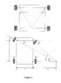
- Figure 3 illustrates example with regards to a steering angle algorithm during turn problem according to one exemplary embodiment of the invention.
- the speed of the inner wheel be Si as indicated in the figure 3 . It is this speed at which the vehicle is turning.
- the outer wheels have to cover more distance as compared to the inner wheels and hence the outer wheels need to rotate faster.
- the required steering angle can be read from driver input.
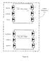
- FIG. 4 illustrates the architecture for a four wheel drive multi motor solution for an electric vehicle according to various exemplary embodiments of the invention.
- a four wheel drive assembly200 comprises of a drive means electrically connected with all motors for driving all wheels independently.
- the assembly200 comprises of four motors 201a, 201b, 201c, and 201d coupled to all four wheels respectively.
- the drive train assembly 200 further comprises four inverters 202a, 202b, 202c and 202d connected to the motor via a three phase alternating current (AC)bus.
- the inverters convert DC power into three phase electricity of varying frequency allowing for speed control of the four motors.
- the drive train assembly 200 further comprises the elements to provide indication of driver intent 220.
- the driver inputs comprises of a means for calculating a rotational speed value for inter-wheel coordination associated with driver inputs and current instantaneous wheel rotational speeds; a means for calculating a wheel acceleration of each of the wheel; a means for determining a steer angle associated with a steering input from the driver; a means for determining and controlling an input frequency to each drive of the motor; and a means for initiating a limp mode for enabling to reduce the power consumption.
- the driver input comprises a group of sensors for sensing the various driver input.
- the sensors used are a steering angle sensor 220b provides indication of direction; an accelerator sensor 220c adapted to give an indication to desire speed; a brake pedal sensor 220d adapted to give an indication of driver intention to slow down or stop.
- the drive train assembly 200 further comprising Park, Neutral, Reverse, Drive (PNRD) means 220a adapted to provide indication to park, engage forward direction or reverse direction
- the PRND means comprises of sensor.
- Park, Neutral, Reverse, Drive means refers to the control lever commonly used with automatic transmissions.
- the drive train assembly 200 further comprises an embedded controller device.
- the embedded controller device is a Vehicle Control Unit (VCU) 210.
- the Vehicle Control Unit (VCU) 210 is embedded with software code that allows control of the motors 201 a, 201 b, 201c and 201d.
- the Vehicle Control Unit (VCU) 210 receives inputs from driver and feedback from the wheel indicating the speed of individual wheels via accelerator sensors 120c disclosed above.
- the assembly200 comprises a vehicle control unit 210 embedded with software code that allows control of the motors.
- the Vehicle Control Unit (VCU) 210 receives inputs from driver and feedback from the wheel indicating the speed of individual wheels via accelerator sensors 220c disclosed above.
- the drive train assembly 200 further comprises plug-in 204, battery charger 206, and combination of battery, BMS and battery switchgear to charge the inverters for providing power to motor coupled with the wheels.
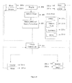
- Figure 5 illustrates architecture of the embedded software according to exemplary embodiment of the invention.
- Architecture of the embedded software comprises of Sensor Components 501, Manager Components 502, Actuator Components 503, Communication Components 504 and Control Algorithm 506.
- the sensor component 501 enables a measurable response to a physical condition like indication of direction, indication to desire speed, an indication of driver intention.
- Software components will read the physical sensor inputs and update the storage variables periodically.
- the sensor component 501 may comprises a steering angle sensor to provide indication of direction, an accelerator sensor adapted to give an indication to desire speed, a brake pedal sensor adapted to give an indication of driver intention to slow down or stop and Park, Neutral, Reverse, Drive (PNRD) means adapted to provide indication to park, engage forward direction or reverse direction.
- PNRD Neutral, Reverse, Drive
- the manager components 502 based on sensor component inputs, the algorithm and control logic will drive the actuator and communication components.
- the manager components 502 further comprises control algorithm 506 wherein the control logic will be developed with addressing the essential safety requirements.
- the manager components 502 will calculate the acceleration, steering angle, and regeneration braking logic via an inputs receive from sensor components 501.
- the actuator components 503 enables for moving or controlling a mechanism or assembly.
- Software components will drive the physical actuators such as motor drives (inverter/s for motor control), contactors etc. as applicable.
- communication components 504 enables for communication activity for sending and receiving messages.
- the software components will transmit and receive messages via CAN bus to/from Motor drives and communication with ABS ECU only for monitoring wheel speed in case it is not monitored through stand-alone sensors.
- the provision to connect to any other ECUs as ancillary systems such as Battery Management System, Infotainment System, and HVAC system will be over CAN bus.
- the technical advancements of the present invention include:
Landscapes
- Engineering & Computer Science (AREA)
- Power Engineering (AREA)
- Transportation (AREA)
- Mechanical Engineering (AREA)
- Electric Propulsion And Braking For Vehicles (AREA)
- Arrangement And Mounting Of Devices That Control Transmission Of Motive Force (AREA)
- Arrangement And Driving Of Transmission Devices (AREA)
Abstract
Description
- The present invention relates to a wheel drive train assembly adapted to control and optimize running state performance of at least two wheels of an electrical vehicle. The invention can be extended to four wheels. Specifically the invention relates to an electric vehicle that has a drive means electrically connected with each motor for driving each wheel independently butin a coordinated manner.
- Conventional vehicles drive the wheels through power derived from a single discrete source, i.e. engine. The power is transferred to the wheels via a transmission and gear mechanism to achieve rotation of wheels.Manufacturers generally employ two wheel drive or four wheel drive for driving the vehicle.
- In a condition wherein the vehicle is driven in straight line, all wheels of vehicle are rotating at the same speed and can be driven easily from a single source. However, while turning the vehicle or in conditions of wheel slip, the corresponding wheels are required to rotate at different speeds even though they all are deriving their motion from a single source. To mitigate this problem generally mechanical gear and differential coupling assemblies are employed that allow wheels to rotate at different speeds.
- These mechanical assemblies have limitations which result in the following problems:
- a) Limitations in wheel speed synchronization during hard cornering conditions.
- b) Inability to easily recover from complete loss of traction of one wheel.
- c) Lack of uniform tractioning in all weather conditions.
- d) Dependent on steering geometry and weight distribution of the vehicle, the appearance of under steer or over steer.
- The two wheel drive architecture is available with front wheel drive and rear wheel drive variants. Both of these variants suffer from the aforesaid general problems.
- In case of four wheel drive architecture, all four wheels or at least pair thereof is expected to be driven independently. The four wheel drive gives significant benefits such as superior traction in all weather conditions, superior driving experience for drivere.t.c. Four wheel drives is implemented by a precise traction control inter-engaged with various mechanical means which are in addition to any mechanical devices already in place to achieve two wheel drives. These devices add inefficiencies and weight to the vehicle. Also, because of the nature of the mechanical mechanisms, a wide range of control is impossible.
- Thus there exists a need to address the long standing problem of achieving four wheel or two wheel drive architecture having less mechanical complexity, less weight and by extension less cost. Thewheel drive system should also have a wider range of control which will enable superior tractions in all weather conditions and increased safety at the limits of handling.
- As discussed earlier, conventional internal combustion engine drive systems are based on a single source and mechanical solutions. These have shortcomings and range of capability which can be overcome by the proposed invention.
- The principal object of the invention is to provide alternate drive train architecture for driving an electric vehicle enabling drivability, handling, safety and range.
- Another object of the invention is to provide two modes of driving viz. economy and normal driving controlled by an embedded controller device thereby adjusting a combination of motor speed, power and ancillary consumption,the second mode will extend the range in the electric vehicle.
- A further object of the invention is to provide indication to the driver of signalintent regarding speed, brakes, and indication of direction via a sensor means built into the electric vehicle.
- Still another object of the invention is to provide a feedback and enhance control capabilities to driver for a devising a wide variety of multi wheel drive systems and responses.
- Before the assembly, components and methods are described, it is to be understood that this invention is not limited to the particular assembly and methods described, as there can be multiple possible embodiments of the present invention, which are not expressly defined in the present disclosure. It is also to be understood that the terminology used in the description is for the purpose of describing the particular versions or embodiments only, and is not intended to limit the scope of the present invention which will be limited only by the appended claims.
- In one aspect of the invention, a drive train assembly is provided to control and optimize running state performance of at least two wheels of an electric vehicle, comprisingat least two front steerable wheels and at least two rear non-steered wheel, each wheel individually coupled with a motor; a drive means electrically coupled with each motor for driving the coupled wheel independent of other wheel of said electric vehicle; and
- an embedded controller device and a memory having executable instructions to control and coordinate varying frequency of inverters attached to vehicle wheel motors based on driver inputs including steering angle, acceleration, brake force, and feedback value as input parameters from each wheel thereby selectively controlling speed of wheels resulting in coordinated driving performance of the vehicle.
- In another aspect of the invention, a method is provided to control and optimize running state performance of at least two wheels of an electric vehicle via an embedded controller device adapted to control state values including rotational speed value, steering angle, and brake force of the vehicle, the method comprising; sensing a first state value of the vehicle; receiving a request for second state values of the vehicle from vehicle driver; altering the first state values of the vehicle to the second state values by controlling the driver input to the corresponding wheel; calculating running state coordination ratio of at least two wheels; and controlling the operation of drive means, and motors in accordance with running state coordination ratio of at least two wheels of the electric vehicle.
- In another aspect of the invention, an assembly is provided for wheel drive architecture comprising a motor coupled with each wheel respectively and control via a Vehicle Control Unit (VCU) to coordinate the wheels respectively. The VCU receives input from sensors that indicate driver intent viz acceleration and braking and using software algorithms, produces signals that control each motor. This mechanism ensures that the motors follow accurately driver intent where this is appropriate.
- In another aspect of the invention, a drive train assembly is provided for enabling driver two modes of driving i.e. economy and normal drive.
- In an another aspect of the invention, a drive train assembly is provided for driving two or four wheels in coordinated manner such that superior control can be achieved over individual wheel rotational speed.
-
- The foregoing summary, as well as the following detailed description of preferred embodiments, is better understood when read in conjunction with the appended drawings. For the purpose of illustrating the invention, there is shown in the drawings example constructions of the invention; however, the invention is not limited to the specific assembly and methods disclosed in the drawings: The present invention will now be described with reference to the accompanying drawing, in which:
-
Figure 1 illustrates a modeling architecture for a two wheel drive multi motor solution according to various exemplary embodiments of the invention. -
Figure 2 illustrates a functioning of vehicle control unit (VCU) according to exemplary embodiments of the invention. -
Figure 3 illustrates example with regards to a steering angle algorithm during turn problem according to one exemplary embodiment of the invention. -
Figure 4 illustrates the architecture for a four wheel drive multi motor solution according to various exemplary embodiments of the invention. -
Figure 5 (a,b,c,d) illustratesarchitecture of the embedded software according to exemplary embodiment of the invention.
-
- Some embodiments of this invention, illustrating all its features, will now be discussed in detail. The words "comprising," "having," "containing," and "including," and other forms thereof, are intended to be equivalent in meaning and be open ended in that an item or items following any one of these words is not meant to be an exhaustive listing of such item or items, or meant to be limited to only the listed item or items. It must also be noted that as used herein and in the appended claims, the singular forms "a," "an," and "the" include plural references unless the context clearly dictates otherwise. Although any assemblies and methods similar or equivalent to those described herein can be used in the practice or testing of embodiments of the present invention, the preferred, systems, assemblies and methods are now described. The disclosed embodiments are merely exemplary of the invention, which may be embodied in various forms.
- A drive train assembly adapted to control and optimize running state performance of at least two wheels of an electric vehicle, comprising:at least two front steerable wheels and at least two rear non-steered wheel, each wheel individually coupled with a motor; a drive means electrically coupled with each motor for driving the coupled wheel independent of other wheel of said electric vehicle; and an embedded controller device and a memory having executable instructions to control and coordinate varying frequency of inverters attached to vehicle wheel motors based on driver inputs including steering angle, acceleration, brake force, and feedback value as input parameters from each wheel thereby selectively controlling speed of wheels resulting in coordinated driving performance of the vehicle.
-
Figure 1 illustrates a modeling architecture for a two wheel drive multi motor solution for an electric vehicle. - Referring to
figure. 1 , a drive train assembly 100 comprises of a drive means electrically connected with at least one motor for driving at least one wheel independently. According to preferred embodiment of the invention a drive train assembly 100 comprises a two motor 101a and 101b coupled with the two wheels. The inverters 102a and 102b coupled to the motor 101a and 102b via a three phase alternating current (AC) bus. The inverter 102 a and 102b convert DC power from the battery into three phase electricity of varying frequency allowing for speed control of the motor 101a and 101b. - According to another embodiment of the invention a drive train assembly 100, further comprises of a
driver input 120. The driver inputs comprises of a means for calculating a rotational speed value for inter-wheel coordination associated with driver inputs and current instantaneous wheel rotational speeds; a means for calculating a wheel acceleration of each of the wheel; a means for determining a steer angle associated with a steering input from the driver; a means for determining the brake force required by the driver; a means for determining and controlling an input frequency to each drive of the motor; and a means for initiating a limp mode for enabling to reduce the power consumption. - According to preferred embodiment of the invention the driver input comprises a group of sensors for sensing the various driver input. According to exemplary embodiment of the invention the sensors used are a steering angle sensor 120b provides indication of direction; an accelerator sensor 120c adapted to give an indication to desire speed; a brake pedal sensor 120d adapted to give an indication of driver intention to slow down or stop.
- According to another embodiment of the invention a drive train assembly 100, further comprising Park, Neutral, Reverse, Drive (PNRD) means adapted to provide indication to park, engage forward direction or reverse direction, the PRND means comprises of sensor. Park, Neutral, Reverse, Drive refers to the control lever commonly used with automatic transmissions.
- According to another embodiment of the invention a drive train assembly 100, further comprisesan embedded controller device. In a preferred embodiment the embedded controller device is a Vehicle Control Unit (VCU) 110. The Vehicle Control Unit (VCU) 110 is embedded with software code that allows control of the motors 101a and 101b. The Vehicle Control Unit (VCU) 110 receives inputs from driver and feedback from the wheel indicating the speed of individual wheels via accelerator sensors 120c disclosed above. This feedback and control capability can be used to provide a wide variety of multi wheel drive features (as shown in
figure 2 ). - According to another embodiment of the invention the response time for the embedded controller device is less than 10 milliseconds upon receiving the inputs from a driver.
- According to another embodiment of the invention a drive train assembly 100, further comprises plug-in 104,
battery charger 106, and combination of battery, BMS and battery switchgear to operate the inverters 102a and 102b for providing power to motor 101a and 101b coupled with the wheels. -
Figure 3 illustrates example with regards to a steering angle algorithm during turn problem according to one exemplary embodiment of the invention. Referring tofigure 3 , consider for two drive means and assume that the vehicle is moving in the right direction. Let the speed of the inner wheel be Si as indicated in thefigure 3 . It is this speed at which the vehicle is turning. The outer wheels have to cover more distance as compared to the inner wheels and hence the outer wheels need to rotate faster. - Let the speed of the outer wheels be So.To complete the full circle, time taken by the inner wheels is 'Ti' which is same as that of the outer wheels say 'To'.


(For inner wheels)
(For outer wheels)

- From
equations 

Final governing equation for Outer and Inner wheel speed
Where, - I - Wheel base
- b- Track width
- The required steering angle can be read from driver input.
- The above equation relates to the case of adjusting wheel speed strictly to take into account a turning radius. The equation can be modified as follows:

- Variation of the constant K can result in certain additional features offered by the two wheel architecture. These are listed as below:
- 1. If K is set to some positive value, then so will be slightly increased and the turning radius will be increased. This effect is limited by tire scrub but will help with driver effort, turning radius and vehicle feel.
- 2. In the case of under steer, K can be set to a positive value to compensate for this behavior
- 3. In the case of over steer, K can be set to a negative value to compensate for this behavior.
- As mentioned previously, electric vehicles are limited in range by available energy in the battery. Any strategy that reduces energy drain on the battery will result in increased range. As an approach to transferring this effect into a choice for the driver, it is possible to present two or modes of operation. For example, assuming there are two modes: normal and economy. Normal would not restrict any functions in the vehicle. However, economy could affect some vehicle functions as listed below:
- 1. Reduce power available to the drive train so that performance is reduced
- 2. Disable certain functions such as power windows, power steering
- 3. Reduce or eliminate cabin heating or cooling
- 4. Disable lighting functions that are not required by regulation.
- With four wheel drive architecture, it is possible to drive only two wheels at a time while disabling two motors. This would reduce power consumption from the battery and allows the possibility of a "limp mode". At times when battery energy is almost finished, application of two wheels only drive would allow for an extended range.
-
Figure 4 illustrates the architecture for a four wheel drive multi motor solution for an electric vehicle according to various exemplary embodiments of the invention. A four wheel drive assembly200 comprises of a drive means electrically connected with all motors for driving all wheels independently. According to preferred embodiment of the invention, the assembly200 comprises of four motors 201a, 201b, 201c, and 201d coupled to all four wheels respectively. Thedrive train assembly 200 further comprises four inverters 202a, 202b, 202c and 202d connected to the motor via a three phase alternating current (AC)bus. The inverters convert DC power into three phase electricity of varying frequency allowing for speed control of the four motors. - According to one embodiment of the invention the
drive train assembly 200, further comprises the elements to provide indication ofdriver intent 220. The driver inputs comprises of a means for calculating a rotational speed value for inter-wheel coordination associated with driver inputs and current instantaneous wheel rotational speeds; a means for calculating a wheel acceleration of each of the wheel; a means for determining a steer angle associated with a steering input from the driver; a means for determining and controlling an input frequency to each drive of the motor; and a means for initiating a limp mode for enabling to reduce the power consumption. - According to preferred embodiment of the invention the driver input comprises a group of sensors for sensing the various driver input. According to exemplary embodiment of the invention the sensors used are a steering angle sensor 220b provides indication of direction; an accelerator sensor 220c adapted to give an indication to desire speed; a brake pedal sensor 220d adapted to give an indication of driver intention to slow down or stop.
- According to another embodiment of the invention the
drive train assembly 200, further comprising Park, Neutral, Reverse, Drive (PNRD) means 220a adapted to provide indication to park, engage forward direction or reverse direction, the PRND means comprises of sensor. Park, Neutral, Reverse, Drive means refers to the control lever commonly used with automatic transmissions. - According to another embodiment of the invention the
drive train assembly 200, further comprises an embedded controller device. In a preferred embodiment the embedded controller device is a Vehicle Control Unit (VCU) 210. The Vehicle Control Unit (VCU) 210 is embedded with software code that allows control of the motors 201 a, 201 b, 201c and 201d. The Vehicle Control Unit (VCU) 210 receives inputs from driver and feedback from the wheel indicating the speed of individual wheels via accelerator sensors 120c disclosed above. - The assembly200 comprises a
vehicle control unit 210 embedded with software code that allows control of the motors. The Vehicle Control Unit (VCU) 210 receives inputs from driver and feedback from the wheel indicating the speed of individual wheels via accelerator sensors 220c disclosed above. - The
drive train assembly 200 further comprises plug-in 204,battery charger 206, and combination of battery, BMS and battery switchgear to charge the inverters for providing power to motor coupled with the wheels. -
Figure 5 (a,b,c,d) illustrates architecture of the embedded software according to exemplary embodiment of the invention. Architecture of the embedded software comprises ofSensor Components 501,Manager Components 502,Actuator Components 503, Communication Components 504 andControl Algorithm 506. - According to an embodiment the
sensor component 501 enables a measurable response to a physical condition like indication of direction, indication to desire speed, an indication of driver intention. Software components will read the physical sensor inputs and update the storage variables periodically. Thesensor component 501 may comprises a steering angle sensor to provide indication of direction, an accelerator sensor adapted to give an indication to desire speed, a brake pedal sensor adapted to give an indication of driver intention to slow down or stop and Park, Neutral, Reverse, Drive (PNRD) means adapted to provide indication to park, engage forward direction or reverse direction. - According to an embodiment, the
manager components 502 based on sensor component inputs, the algorithm and control logic will drive the actuator and communication components. Themanager components 502 further comprisescontrol algorithm 506 wherein the control logic will be developed with addressing the essential safety requirements. Themanager components 502 will calculate the acceleration, steering angle, and regeneration braking logic via an inputs receive fromsensor components 501. - According to an embodiment, the
actuator components 503 enables for moving or controlling a mechanism or assembly. Software components will drive the physical actuators such as motor drives (inverter/s for motor control), contactors etc. as applicable. - According to an embodiment, communication components 504 enables for communication activity for sending and receiving messages. The software components will transmit and receive messages via CAN bus to/from Motor drives and communication with ABS ECU only for monitoring wheel speed in case it is not monitored through stand-alone sensors. The provision to connect to any other ECUs as ancillary systems such as Battery Management System, Infotainment System, and HVAC system will be over CAN bus.
- The technical advancements of the present invention include:
- 1) Provide a superior traction to a vehicle in all weather condition;
- 2) Provide an increased safety condition where an automobile is pushed to limits of its handling capacity;
- 3) Provide a superior driving experience for driver of a vehicle;
- 4) Provide an ability to correct under steer and over steer conditions ;
- 5) Provide less mechanical complexity in the assembly; and
- 6) Provide dynamic changes in control strategies to suit driving condition.
- 7) Allow a driver to choose between driving modes to allow for range extension at the expense of performance
- 8) Provide a means for a limp mode in the four wheel drive configuration
Claims (11)
- A drive train assembly adapted to control and optimize running state performance of at least two wheels of an electric vehicle, comprising:at least two front steerable wheels and at least two rear non-steered wheel, each wheel individually coupled with a motor;a drive means electrically coupled with each motor for driving the coupled wheel independent of other wheel of said electric vehicle; andan embedded controller device and a memory having executable instructions to control and coordinate varying frequency of inverters attached to vehicle wheel motors based on driver inputs including steering angle, acceleration,brake force, and feedback value as input parameters from each wheel thereby selectively controlling speed of wheels resulting in coordinated driving performance of the vehicle.
- A drive train assembly as defined in claim 1, wherein the electrical vehicle configured for two wheel drive or four wheel drive.
- A drive train assembly as defined in claim 1, further comprising a means for initiating a limp mode for enabling to reduce the power consumption.
- A drive train assembly as defined in claim 1, further comprising Park, Neutral, Reverse, Drive (PNRD) means adapted to provide indication to park, engages forward direction or reverse direction, the PRND means comprises of sensor.
- A drive train assembly as defined in claim 4, wherein the PRND means can include two modes of drive comprises of sport and economy mode.
- A drive train assembly as defined in claim 1, wherein the steer angle is determined by steering angle sensors connected with two or four wheels coupled with controller to provide signals for enabling wheels displacement in coordinated manner respectively.
- A drive train assembly as defined in claim 1, wherein the inverters convert direct current power into three phase electricity of varying frequency for enabling the speed control of vehicle.
- A drive train assembly as defined in claim 1, wherein a response time of the embedded controller device is less than 10 milliseconds upon receiving the inputs from a driver.
- A method adapted to control and optimize running state performance of at least two wheels of an electric vehicle via an embedded controller device adapted to control state values including rotational speed value, steering angle, and brake force of the vehicle, the method comprising;
sensing a first state value of the vehicle;
receiving a request for second state values of the vehicle from vehicle driver; altering the first state values of the vehicle to the second state values by controlling the driver input to the corresponding wheel;
calculating running state coordination ratio of at least two wheels; and controlling the operation of drive means, and motors in accordance with running state coordination ratio of at least two wheels of the electric vehicle. - A method as defined in claim 9, further comprising initiating a limp mode for enabling to reduce the power consumption.
- A method as defined in claim 9, wherein the electrical vehicle configured for two wheel drive or four wheel drive.
Applications Claiming Priority (1)
| Application Number | Priority Date | Filing Date | Title |
|---|---|---|---|
| IN2230MU2011 | 2011-08-08 |
Publications (3)
| Publication Number | Publication Date |
|---|---|
| EP2556990A2 true EP2556990A2 (en) | 2013-02-13 |
| EP2556990A3 EP2556990A3 (en) | 2017-05-10 |
| EP2556990B1 EP2556990B1 (en) | 2019-06-05 |
Family
ID=46754867
Family Applications (1)
| Application Number | Title | Priority Date | Filing Date |
|---|---|---|---|
| EP12177951.6A Not-in-force EP2556990B1 (en) | 2011-08-08 | 2012-07-26 | A wheel drive architecture for electric vehicles |
Country Status (2)
| Country | Link |
|---|---|
| US (1) | US20130041536A1 (en) |
| EP (1) | EP2556990B1 (en) |
Cited By (4)
| Publication number | Priority date | Publication date | Assignee | Title |
|---|---|---|---|---|
| CN107521363A (en) * | 2017-08-14 | 2017-12-29 | 中国重汽集团济南动力有限公司 | The multilevel security protection system and control method of a kind of car locking that charges |
| CN107953801A (en) * | 2017-11-29 | 2018-04-24 | 吉林大学 | A kind of driving force control method of full wheel-hub motor driven vehicle |
| CN109634161A (en) * | 2018-11-06 | 2019-04-16 | 中船华南船舶机械有限公司 | A kind of electrical pushing cylinder electric-control system |
| CN111267634A (en) * | 2018-12-04 | 2020-06-12 | 长沙智能驾驶研究院有限公司 | Vehicle control method and system, electronic device and computer storage medium |
Families Citing this family (5)
| Publication number | Priority date | Publication date | Assignee | Title |
|---|---|---|---|---|
| US10023073B2 (en) * | 2015-10-27 | 2018-07-17 | Thunder Power New Energy Vehicle Development Company Limited | Four motor direct driving system |
| US11046304B2 (en) * | 2018-11-12 | 2021-06-29 | Argo AI, LLC | Rider selectable ride comfort system for autonomous vehicle |
| CN109795343A (en) * | 2019-02-19 | 2019-05-24 | 江苏吉泰科电气股份有限公司 | A kind of combination control method and its device based on wheel side distributed electric automobile |
| CN110293831A (en) * | 2019-08-06 | 2019-10-01 | 厦门金龙联合汽车工业有限公司 | A kind of Direct wheel drives assembly based on sprung mass |
| CN113060014B (en) * | 2021-04-16 | 2023-01-31 | 国家石油天然气管网集团有限公司华南分公司 | Method and device for improving control safety performance of motor |
Family Cites Families (15)
| Publication number | Priority date | Publication date | Assignee | Title |
|---|---|---|---|---|
| JP2863234B2 (en) * | 1989-12-27 | 1999-03-03 | アイシン・エィ・ダブリュ株式会社 | Electric vehicle |
| US5646843A (en) * | 1990-02-05 | 1997-07-08 | Caterpillar Inc. | Apparatus and method for surface based vehicle control system |
| US5258912A (en) * | 1991-06-24 | 1993-11-02 | General Motors Corporation | Wheel understeer speed control |
| JPH05268706A (en) * | 1992-03-19 | 1993-10-15 | Aqueous Res:Kk | Electric car |
| EP0622264B1 (en) * | 1993-04-28 | 1998-11-11 | Hitachi, Ltd. | Electric vehicle drive system and drive method |
| KR970066776A (en) * | 1996-03-29 | 1997-10-13 | 헨리 D.G. 웰레스 | Vehicle control device |
| JP3451848B2 (en) * | 1996-09-10 | 2003-09-29 | トヨタ自動車株式会社 | Drive control device for electric vehicle |
| EP1077527B1 (en) * | 1999-08-18 | 2002-05-29 | Holtz, Joachim, Prof. Dr. Ing. | Method of braking a vector controlled induction machine, control device for carrying out the method and storage medium |
| US6909959B2 (en) * | 2003-03-07 | 2005-06-21 | Stephen James Hallowell | Torque distribution systems and methods for wheeled vehicles |
| RU2290328C1 (en) * | 2005-07-21 | 2006-12-27 | Василий Васильевич Шкондин | All-wheel-drive vehicle |
| US7386379B2 (en) * | 2005-07-22 | 2008-06-10 | Gm Global Technology Operations, Inc. | Method and apparatus to control coordinated wheel motors |
| DE102007008477B4 (en) * | 2006-02-22 | 2018-10-04 | Mitsubishi Fuso Truck And Bus Corp. | Control method for a hybrid electric vehicle |
| EP2026988A2 (en) * | 2006-04-03 | 2009-02-25 | BluWav Systems, LLC | Vehicle power unit designed as retrofittable axle comprising motor, battery and suspension |
| US7658251B2 (en) * | 2006-09-20 | 2010-02-09 | James Harry K | Direct drive electric traction motor |
| US8453770B2 (en) * | 2009-01-29 | 2013-06-04 | Tesla Motors, Inc. | Dual motor drive and control system for an electric vehicle |
-
2012
- 2012-07-26 EP EP12177951.6A patent/EP2556990B1/en not_active Not-in-force
- 2012-07-30 US US13/561,438 patent/US20130041536A1/en not_active Abandoned
Non-Patent Citations (1)
| Title |
|---|
| None |
Cited By (6)
| Publication number | Priority date | Publication date | Assignee | Title |
|---|---|---|---|---|
| CN107521363A (en) * | 2017-08-14 | 2017-12-29 | 中国重汽集团济南动力有限公司 | The multilevel security protection system and control method of a kind of car locking that charges |
| CN107521363B (en) * | 2017-08-14 | 2019-11-08 | 中国重汽集团济南动力有限公司 | A multi-level safety protection system and control method for charging and locking cars |
| CN107953801A (en) * | 2017-11-29 | 2018-04-24 | 吉林大学 | A kind of driving force control method of full wheel-hub motor driven vehicle |
| CN107953801B (en) * | 2017-11-29 | 2018-12-07 | 吉林大学 | A kind of driving force control method of full wheel-hub motor driven vehicle |
| CN109634161A (en) * | 2018-11-06 | 2019-04-16 | 中船华南船舶机械有限公司 | A kind of electrical pushing cylinder electric-control system |
| CN111267634A (en) * | 2018-12-04 | 2020-06-12 | 长沙智能驾驶研究院有限公司 | Vehicle control method and system, electronic device and computer storage medium |
Also Published As
| Publication number | Publication date |
|---|---|
| US20130041536A1 (en) | 2013-02-14 |
| EP2556990B1 (en) | 2019-06-05 |
| EP2556990A3 (en) | 2017-05-10 |
Similar Documents
| Publication | Publication Date | Title |
|---|---|---|
| EP2556990B1 (en) | A wheel drive architecture for electric vehicles | |
| US10793124B2 (en) | Vehicle wheel torque control systems and methods | |
| CN108216240B (en) | Method and apparatus for controlling front and rear wheel torque distribution for four-wheel drive vehicle | |
| CN109017747B (en) | Front and rear axle torque distribution method and system of new energy four-wheel drive vehicle and related components | |
| US7104617B2 (en) | Independent braking and controllability control method and system for a vehicle with regenerative braking | |
| CN100391768C (en) | A multi-axle drive system for an oil-electric hybrid vehicle and a method for improving the turning radius of the vehicle by applying the system | |
| US12145573B2 (en) | System and method for vehicle turning radius reduction | |
| AU2011323345B2 (en) | System and method for controlling wheel motor torque in an electric drive system | |
| CN105946851B (en) | A kind of change mould control method of hybrid vehicle Multiple modes coupling drive system | |
| JP2004099029A (en) | Braking and controllability control method and system of vehicle with regenerative braking | |
| US11285818B2 (en) | Driving torque command generating apparatus and method of eco-friendly vehicle | |
| JP2006081343A (en) | Vehicle regenerative braking control device | |
| CN110466361B (en) | Vehicle control unit of pure electric vehicle driven by two-wheel hub motor and control method | |
| CN109017439A (en) | A kind of pure electric automobile Two-mode Coupling driving control system and control method | |
| CN109747613B (en) | Motor vehicle | |
| CA2934229C (en) | Slip determination system for vehicle | |
| JP2014114002A (en) | Driving torque control method and system for vehicle | |
| CN103930303A (en) | Electric automobile | |
| US12054161B2 (en) | Traction motor based wheel speed recovery | |
| CN114834265A (en) | Vehicle driving control method and device, vehicle and storage medium | |
| EP1714845B1 (en) | Vehicle driving system | |
| AU2011323346A1 (en) | System and method for controlling traction | |
| CN2925948Y (en) | Multi-bridge driving system of mixed-dynamic vehicle | |
| KR100598805B1 (en) | Regenerative Braking Control Method and System for 4WD Electric Vehicles | |
| CN113561950B (en) | Stability control method and device for distributed driving electric automobile and electric automobile |
Legal Events
| Date | Code | Title | Description |
|---|---|---|---|
| PUAI | Public reference made under article 153(3) epc to a published international application that has entered the european phase |
Free format text: ORIGINAL CODE: 0009012 |
|
| 17P | Request for examination filed |
Effective date: 20120726 |
|
| AK | Designated contracting states |
Kind code of ref document: A2 Designated state(s): AL AT BE BG CH CY CZ DE DK EE ES FI FR GB GR HR HU IE IS IT LI LT LU LV MC MK MT NL NO PL PT RO RS SE SI SK SM TR |
|
| AX | Request for extension of the european patent |
Extension state: BA ME |
|
| PUAL | Search report despatched |
Free format text: ORIGINAL CODE: 0009013 |
|
| AK | Designated contracting states |
Kind code of ref document: A3 Designated state(s): AL AT BE BG CH CY CZ DE DK EE ES FI FR GB GR HR HU IE IS IT LI LT LU LV MC MK MT NL NO PL PT RO RS SE SI SK SM TR |
|
| AX | Request for extension of the european patent |
Extension state: BA ME |
|
| RIC1 | Information provided on ipc code assigned before grant |
Ipc: B60L 15/20 20060101AFI20170405BHEP |
|
| STAA | Information on the status of an ep patent application or granted ep patent |
Free format text: STATUS: EXAMINATION IS IN PROGRESS |
|
| 17Q | First examination report despatched |
Effective date: 20180103 |
|
| GRAP | Despatch of communication of intention to grant a patent |
Free format text: ORIGINAL CODE: EPIDOSNIGR1 |
|
| STAA | Information on the status of an ep patent application or granted ep patent |
Free format text: STATUS: GRANT OF PATENT IS INTENDED |
|
| INTG | Intention to grant announced |
Effective date: 20180822 |
|
| GRAJ | Information related to disapproval of communication of intention to grant by the applicant or resumption of examination proceedings by the epo deleted |
Free format text: ORIGINAL CODE: EPIDOSDIGR1 |
|
| STAA | Information on the status of an ep patent application or granted ep patent |
Free format text: STATUS: EXAMINATION IS IN PROGRESS |
|
| GRAP | Despatch of communication of intention to grant a patent |
Free format text: ORIGINAL CODE: EPIDOSNIGR1 |
|
| STAA | Information on the status of an ep patent application or granted ep patent |
Free format text: STATUS: GRANT OF PATENT IS INTENDED |
|
| INTC | Intention to grant announced (deleted) | ||
| INTG | Intention to grant announced |
Effective date: 20190204 |
|
| GRAS | Grant fee paid |
Free format text: ORIGINAL CODE: EPIDOSNIGR3 |
|
| GRAA | (expected) grant |
Free format text: ORIGINAL CODE: 0009210 |
|
| STAA | Information on the status of an ep patent application or granted ep patent |
Free format text: STATUS: THE PATENT HAS BEEN GRANTED |
|
| AK | Designated contracting states |
Kind code of ref document: B1 Designated state(s): AL AT BE BG CH CY CZ DE DK EE ES FI FR GB GR HR HU IE IS IT LI LT LU LV MC MK MT NL NO PL PT RO RS SE SI SK SM TR |
|
| REG | Reference to a national code |
Ref country code: GB Ref legal event code: FG4D |
|
| REG | Reference to a national code |
Ref country code: CH Ref legal event code: EP |
|
| REG | Reference to a national code |
Ref country code: AT Ref legal event code: REF Ref document number: 1139642 Country of ref document: AT Kind code of ref document: T Effective date: 20190615 |
|
| REG | Reference to a national code |
Ref country code: IE Ref legal event code: FG4D |
|
| REG | Reference to a national code |
Ref country code: DE Ref legal event code: R096 Ref document number: 602012060666 Country of ref document: DE |
|
| REG | Reference to a national code |
Ref country code: NL Ref legal event code: MP Effective date: 20190605 |
|
| REG | Reference to a national code |
Ref country code: LT Ref legal event code: MG4D |
|
| PG25 | Lapsed in a contracting state [announced via postgrant information from national office to epo] |
Ref country code: LT Free format text: LAPSE BECAUSE OF FAILURE TO SUBMIT A TRANSLATION OF THE DESCRIPTION OR TO PAY THE FEE WITHIN THE PRESCRIBED TIME-LIMIT Effective date: 20190605 Ref country code: HR Free format text: LAPSE BECAUSE OF FAILURE TO SUBMIT A TRANSLATION OF THE DESCRIPTION OR TO PAY THE FEE WITHIN THE PRESCRIBED TIME-LIMIT Effective date: 20190605 Ref country code: ES Free format text: LAPSE BECAUSE OF FAILURE TO SUBMIT A TRANSLATION OF THE DESCRIPTION OR TO PAY THE FEE WITHIN THE PRESCRIBED TIME-LIMIT Effective date: 20190605 Ref country code: SE Free format text: LAPSE BECAUSE OF FAILURE TO SUBMIT A TRANSLATION OF THE DESCRIPTION OR TO PAY THE FEE WITHIN THE PRESCRIBED TIME-LIMIT Effective date: 20190605 Ref country code: FI Free format text: LAPSE BECAUSE OF FAILURE TO SUBMIT A TRANSLATION OF THE DESCRIPTION OR TO PAY THE FEE WITHIN THE PRESCRIBED TIME-LIMIT Effective date: 20190605 Ref country code: NO Free format text: LAPSE BECAUSE OF FAILURE TO SUBMIT A TRANSLATION OF THE DESCRIPTION OR TO PAY THE FEE WITHIN THE PRESCRIBED TIME-LIMIT Effective date: 20190905 Ref country code: AL Free format text: LAPSE BECAUSE OF FAILURE TO SUBMIT A TRANSLATION OF THE DESCRIPTION OR TO PAY THE FEE WITHIN THE PRESCRIBED TIME-LIMIT Effective date: 20190605 |
|
| PG25 | Lapsed in a contracting state [announced via postgrant information from national office to epo] |
Ref country code: GR Free format text: LAPSE BECAUSE OF FAILURE TO SUBMIT A TRANSLATION OF THE DESCRIPTION OR TO PAY THE FEE WITHIN THE PRESCRIBED TIME-LIMIT Effective date: 20190906 Ref country code: LV Free format text: LAPSE BECAUSE OF FAILURE TO SUBMIT A TRANSLATION OF THE DESCRIPTION OR TO PAY THE FEE WITHIN THE PRESCRIBED TIME-LIMIT Effective date: 20190605 Ref country code: RS Free format text: LAPSE BECAUSE OF FAILURE TO SUBMIT A TRANSLATION OF THE DESCRIPTION OR TO PAY THE FEE WITHIN THE PRESCRIBED TIME-LIMIT Effective date: 20190605 Ref country code: BG Free format text: LAPSE BECAUSE OF FAILURE TO SUBMIT A TRANSLATION OF THE DESCRIPTION OR TO PAY THE FEE WITHIN THE PRESCRIBED TIME-LIMIT Effective date: 20190905 |
|
| REG | Reference to a national code |
Ref country code: AT Ref legal event code: MK05 Ref document number: 1139642 Country of ref document: AT Kind code of ref document: T Effective date: 20190605 |
|
| PG25 | Lapsed in a contracting state [announced via postgrant information from national office to epo] |
Ref country code: RO Free format text: LAPSE BECAUSE OF FAILURE TO SUBMIT A TRANSLATION OF THE DESCRIPTION OR TO PAY THE FEE WITHIN THE PRESCRIBED TIME-LIMIT Effective date: 20190605 Ref country code: SK Free format text: LAPSE BECAUSE OF FAILURE TO SUBMIT A TRANSLATION OF THE DESCRIPTION OR TO PAY THE FEE WITHIN THE PRESCRIBED TIME-LIMIT Effective date: 20190605 Ref country code: CZ Free format text: LAPSE BECAUSE OF FAILURE TO SUBMIT A TRANSLATION OF THE DESCRIPTION OR TO PAY THE FEE WITHIN THE PRESCRIBED TIME-LIMIT Effective date: 20190605 Ref country code: NL Free format text: LAPSE BECAUSE OF FAILURE TO SUBMIT A TRANSLATION OF THE DESCRIPTION OR TO PAY THE FEE WITHIN THE PRESCRIBED TIME-LIMIT Effective date: 20190605 Ref country code: PT Free format text: LAPSE BECAUSE OF FAILURE TO SUBMIT A TRANSLATION OF THE DESCRIPTION OR TO PAY THE FEE WITHIN THE PRESCRIBED TIME-LIMIT Effective date: 20191007 Ref country code: EE Free format text: LAPSE BECAUSE OF FAILURE TO SUBMIT A TRANSLATION OF THE DESCRIPTION OR TO PAY THE FEE WITHIN THE PRESCRIBED TIME-LIMIT Effective date: 20190605 Ref country code: AT Free format text: LAPSE BECAUSE OF FAILURE TO SUBMIT A TRANSLATION OF THE DESCRIPTION OR TO PAY THE FEE WITHIN THE PRESCRIBED TIME-LIMIT Effective date: 20190605 |
|
| REG | Reference to a national code |
Ref country code: DE Ref legal event code: R119 Ref document number: 602012060666 Country of ref document: DE |
|
| PG25 | Lapsed in a contracting state [announced via postgrant information from national office to epo] |
Ref country code: SM Free format text: LAPSE BECAUSE OF FAILURE TO SUBMIT A TRANSLATION OF THE DESCRIPTION OR TO PAY THE FEE WITHIN THE PRESCRIBED TIME-LIMIT Effective date: 20190605 Ref country code: IS Free format text: LAPSE BECAUSE OF FAILURE TO SUBMIT A TRANSLATION OF THE DESCRIPTION OR TO PAY THE FEE WITHIN THE PRESCRIBED TIME-LIMIT Effective date: 20191005 Ref country code: IT Free format text: LAPSE BECAUSE OF FAILURE TO SUBMIT A TRANSLATION OF THE DESCRIPTION OR TO PAY THE FEE WITHIN THE PRESCRIBED TIME-LIMIT Effective date: 20190605 |
|
| REG | Reference to a national code |
Ref country code: CH Ref legal event code: PL |
|
| PG25 | Lapsed in a contracting state [announced via postgrant information from national office to epo] |
Ref country code: MC Free format text: LAPSE BECAUSE OF FAILURE TO SUBMIT A TRANSLATION OF THE DESCRIPTION OR TO PAY THE FEE WITHIN THE PRESCRIBED TIME-LIMIT Effective date: 20190605 Ref country code: TR Free format text: LAPSE BECAUSE OF FAILURE TO SUBMIT A TRANSLATION OF THE DESCRIPTION OR TO PAY THE FEE WITHIN THE PRESCRIBED TIME-LIMIT Effective date: 20190605 |
|
| PLBE | No opposition filed within time limit |
Free format text: ORIGINAL CODE: 0009261 |
|
| STAA | Information on the status of an ep patent application or granted ep patent |
Free format text: STATUS: NO OPPOSITION FILED WITHIN TIME LIMIT |
|
| REG | Reference to a national code |
Ref country code: BE Ref legal event code: MM Effective date: 20190731 |
|
| PG25 | Lapsed in a contracting state [announced via postgrant information from national office to epo] |
Ref country code: PL Free format text: LAPSE BECAUSE OF FAILURE TO SUBMIT A TRANSLATION OF THE DESCRIPTION OR TO PAY THE FEE WITHIN THE PRESCRIBED TIME-LIMIT Effective date: 20190605 Ref country code: DK Free format text: LAPSE BECAUSE OF FAILURE TO SUBMIT A TRANSLATION OF THE DESCRIPTION OR TO PAY THE FEE WITHIN THE PRESCRIBED TIME-LIMIT Effective date: 20190605 Ref country code: DE Free format text: LAPSE BECAUSE OF NON-PAYMENT OF DUE FEES Effective date: 20200201 |
|
| 26N | No opposition filed |
Effective date: 20200306 |
|
| PG25 | Lapsed in a contracting state [announced via postgrant information from national office to epo] |
Ref country code: LI Free format text: LAPSE BECAUSE OF NON-PAYMENT OF DUE FEES Effective date: 20190731 Ref country code: CH Free format text: LAPSE BECAUSE OF NON-PAYMENT OF DUE FEES Effective date: 20190731 Ref country code: SI Free format text: LAPSE BECAUSE OF FAILURE TO SUBMIT A TRANSLATION OF THE DESCRIPTION OR TO PAY THE FEE WITHIN THE PRESCRIBED TIME-LIMIT Effective date: 20190605 Ref country code: BE Free format text: LAPSE BECAUSE OF NON-PAYMENT OF DUE FEES Effective date: 20190731 Ref country code: LU Free format text: LAPSE BECAUSE OF NON-PAYMENT OF DUE FEES Effective date: 20190726 |
|
| PG25 | Lapsed in a contracting state [announced via postgrant information from national office to epo] |
Ref country code: FR Free format text: LAPSE BECAUSE OF NON-PAYMENT OF DUE FEES Effective date: 20190805 Ref country code: IE Free format text: LAPSE BECAUSE OF NON-PAYMENT OF DUE FEES Effective date: 20190726 |
|
| GBPC | Gb: european patent ceased through non-payment of renewal fee |
Effective date: 20190905 |
|
| PG25 | Lapsed in a contracting state [announced via postgrant information from national office to epo] |
Ref country code: GB Free format text: LAPSE BECAUSE OF NON-PAYMENT OF DUE FEES Effective date: 20190905 |
|
| PG25 | Lapsed in a contracting state [announced via postgrant information from national office to epo] |
Ref country code: CY Free format text: LAPSE BECAUSE OF FAILURE TO SUBMIT A TRANSLATION OF THE DESCRIPTION OR TO PAY THE FEE WITHIN THE PRESCRIBED TIME-LIMIT Effective date: 20190605 |
|
| PG25 | Lapsed in a contracting state [announced via postgrant information from national office to epo] |
Ref country code: MT Free format text: LAPSE BECAUSE OF FAILURE TO SUBMIT A TRANSLATION OF THE DESCRIPTION OR TO PAY THE FEE WITHIN THE PRESCRIBED TIME-LIMIT Effective date: 20190605 Ref country code: HU Free format text: LAPSE BECAUSE OF FAILURE TO SUBMIT A TRANSLATION OF THE DESCRIPTION OR TO PAY THE FEE WITHIN THE PRESCRIBED TIME-LIMIT; INVALID AB INITIO Effective date: 20120726 |
|
| PG25 | Lapsed in a contracting state [announced via postgrant information from national office to epo] |
Ref country code: MK Free format text: LAPSE BECAUSE OF FAILURE TO SUBMIT A TRANSLATION OF THE DESCRIPTION OR TO PAY THE FEE WITHIN THE PRESCRIBED TIME-LIMIT Effective date: 20190605 |