EP2556854A1 - Mehrweg-Infusionsleitung - Google Patents
Mehrweg-Infusionsleitung Download PDFInfo
- Publication number
- EP2556854A1 EP2556854A1 EP20120179690 EP12179690A EP2556854A1 EP 2556854 A1 EP2556854 A1 EP 2556854A1 EP 20120179690 EP20120179690 EP 20120179690 EP 12179690 A EP12179690 A EP 12179690A EP 2556854 A1 EP2556854 A1 EP 2556854A1
- Authority
- EP
- European Patent Office
- Prior art keywords
- tubing
- clamp
- door
- fluid
- compartment
- Prior art date
- Legal status (The legal status is an assumption and is not a legal conclusion. Google has not performed a legal analysis and makes no representation as to the accuracy of the status listed.)
- Withdrawn
Links
Images
Classifications
-
- A—HUMAN NECESSITIES
- A61—MEDICAL OR VETERINARY SCIENCE; HYGIENE
- A61M—DEVICES FOR INTRODUCING MEDIA INTO, OR ONTO, THE BODY; DEVICES FOR TRANSDUCING BODY MEDIA OR FOR TAKING MEDIA FROM THE BODY; DEVICES FOR PRODUCING OR ENDING SLEEP OR STUPOR
- A61M5/00—Devices for bringing media into the body in a subcutaneous, intra-vascular or intramuscular way; Accessories therefor, e.g. filling or cleaning devices, arm-rests
- A61M5/14—Infusion devices, e.g. infusing by gravity; Blood infusion; Accessories therefor
- A61M5/168—Means for controlling media flow to the body or for metering media to the body, e.g. drip meters, counters ; Monitoring media flow to the body
- A61M5/16804—Flow controllers
- A61M5/16827—Flow controllers controlling delivery of multiple fluids, e.g. sequencing, mixing or via separate flow-paths
-
- A—HUMAN NECESSITIES
- A61—MEDICAL OR VETERINARY SCIENCE; HYGIENE
- A61M—DEVICES FOR INTRODUCING MEDIA INTO, OR ONTO, THE BODY; DEVICES FOR TRANSDUCING BODY MEDIA OR FOR TAKING MEDIA FROM THE BODY; DEVICES FOR PRODUCING OR ENDING SLEEP OR STUPOR
- A61M39/00—Tubes, tube connectors, tube couplings, valves, access sites or the like, specially adapted for medical use
- A61M39/22—Valves or arrangement of valves
- A61M39/28—Clamping means for squeezing flexible tubes, e.g. roller clamps
- A61M39/286—Wedge clamps, e.g. roller clamps with inclined guides
-
- A—HUMAN NECESSITIES
- A61—MEDICAL OR VETERINARY SCIENCE; HYGIENE
- A61M—DEVICES FOR INTRODUCING MEDIA INTO, OR ONTO, THE BODY; DEVICES FOR TRANSDUCING BODY MEDIA OR FOR TAKING MEDIA FROM THE BODY; DEVICES FOR PRODUCING OR ENDING SLEEP OR STUPOR
- A61M5/00—Devices for bringing media into the body in a subcutaneous, intra-vascular or intramuscular way; Accessories therefor, e.g. filling or cleaning devices, arm-rests
- A61M5/14—Infusion devices, e.g. infusing by gravity; Blood infusion; Accessories therefor
- A61M2005/1401—Functional features
- A61M2005/1403—Flushing or purging
-
- A—HUMAN NECESSITIES
- A61—MEDICAL OR VETERINARY SCIENCE; HYGIENE
- A61M—DEVICES FOR INTRODUCING MEDIA INTO, OR ONTO, THE BODY; DEVICES FOR TRANSDUCING BODY MEDIA OR FOR TAKING MEDIA FROM THE BODY; DEVICES FOR PRODUCING OR ENDING SLEEP OR STUPOR
- A61M39/00—Tubes, tube connectors, tube couplings, valves, access sites or the like, specially adapted for medical use
- A61M39/22—Valves or arrangement of valves
- A61M39/28—Clamping means for squeezing flexible tubes, e.g. roller clamps
- A61M39/286—Wedge clamps, e.g. roller clamps with inclined guides
- A61M39/287—Wedge formed by a slot having varying width, e.g. slide clamps
Definitions
- the present invention relates to a multi-channel perfusion line.
- Some medical treatments require the administration of several medical substances under infusion. When these substances are immiscible or need to be sequentially administered, a multi-channel infusion device is often used. However, arrived at the end of injection of an active substance, these devices require the intervention of a qualified operator to initiate the next injection sequence, which complicates the progress of the infusion and increases the risk of error of handling. Such devices also present the risk that the caregiver is in contact with the products often used very toxic.
- An automatic device that is simple to use, that allows sequenced administration, without the intervention of medical personnel and that is perfectly sealed to avoid any risk of contact with toxic substances is therefore desirable.
- the present invention provides an infusion line inexpensive and easy to use. Automatic sequencing is achieved by the action of the programmable control means and the pump. Indeed, the pump performs aspiration from the main tubing regardless of the fluid pocket to infusing, the selection of the fluid infusion bag being obtained by the programmed control means. It is thus possible to inject several fluids of different bags at the same time or in an offset manner.
- the means for controlling the movement of each receiving means of the housing and allows the movement of the clamp for closing and opening the tubing independently for each of the compartments of the housing which secures the sequenced and automatic administration fluid of each compartment according to the programming carried out control means.
- closure clamp corresponds to the term “clamp” often used in the English terminology.
- the programmable control means are integrated in the pump.
- the pump is peristaltic.
- each of the compartments of the housing comprises a door equipped with locking means capable of locking the door to prevent access to the closure clamp in the open position of the tubing.
- locking means capable of locking the door to prevent access to the closure clamp in the open position of the tubing.
- the means for receiving the closure clamp comprises a movable drawer in which the clamp is inserted so as to facilitate the movement of the clamp between its two positions of closing and opening of the tubing and each compartment comprises spans on which the movable spool can move between the open position and the closure position of the clamp.
- the clamp is provided with teeth that snap into holes provided in the drawer so as to ensure the solidarity of the clamp and the drawer during the various movements.
- the spans have the effect of guiding the movement of the drawer between the two positions.
- each compartment comprises elastic return means which urge the drawer towards the closing position of the clamp. The tubing is thus closed even when the drawer is at rest, which prevents the accidental release of fluid.
- the elastic rappelling means are typically made of springs.
- each compartment comprises a means for controlling the movable drawer between an inactive position in which the drawer is held in the closed position of the gripper by the elastic return means and a second active position in which the control means pushes the drawer against the return means in the open position of the clamp.
- control means comprises a lever pivoting on an axis and an electromagnet controlling the movement of the lever between its two active and inactive positions.
- electromagnet controlling the movement of the lever between its two active and inactive positions.
- the locking means of each of the doors comprise two bolts able to move to open and close the door and a locking member designed to move between an unlocked position of the door in which the bolts are free to move to open the door and a locking position of the door in which the locking member comes to immobilize the bolts in the locking position of the door.
- the locking means comprise for example an elastic return device which urges the locking member in the locking position of the door.
- the drawer control means cooperates with the locking member so that when the control means moves from its active position to its inactive position, it causes the locking member to move from its position to locking in its unlocking position, against the elastic return device.
- the control means cleverly initiates the movement of the clamp in the opening position of the tubular at the same time as it causes locking of the compartment door, condemning access to the clamp and securing the administration of the fluid .
- each door of the housing comprises an unlocking member comprising a push button disposed on the door, the unlocking member being arranged so that when pressure is exerted on the push button, the unlocking member causes movement. the locking member from its locking position to its unlocked position, against the elastic return device. It is thus possible to unlock the door from outside the compartment so as to allow its opening, in case of emergency for example.
- the unlocking member comprises a fork pivoting about an axis, a first end of the fork forming the push button and a second end of the fork cooperating with the locking member so as to cause the displacement of the locking member from its locking position to its unlocked position.
- each compartment comprises a drop detection device so as to determine the end of the flow of drops of fluid in the tubing.
- the drop detection device comprises for example an optical cell and / or an ultrasonic device.
- the clamp comprises a window in which the tubing is likely to be engaged and when the clamp is in the closed position, the size of the window is smaller than the diameter of the tubing and when the clamp is in position. opening position, the dimension of the window is greater than the diameter of the tubing.
- the clamp is thus in the form of a pipe closure member of simple design and easy to manufacture.
- Step d) allows in particular to sequence the injection of the different fluids without loss of time between each sequence.
- detecting the end of fluid flow ensures the delivery of all of the medical substance to the patient.
- the process comprises between steps f) and h) a step g) of rinsing the main pipe to which the pipes are connected downstream, consisting in the displacement of the receiving means of the clamp equipped with the tubing of the fluid rinsing in the open position of the tubing for the time necessary for the delivery of a predefined dose of rinsing fluid.
- the main tubing, through which each medical substance is administered is rinsed. This allows on the one hand to inject the patient residual traces of active substances remaining on the walls of the tubes and other to avoid mixing the substances to be administered.
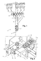
- the figure 1 represents a multichannel infusion line 1 comprising a housing 2 having several compartments 3 and 4 pockets containing different fluids to administer to the patient. Each pocket 4 has been pre-filled with a fluid under a sterile atmosphere to avoid any contamination.
- the fluid is mainly composed of a serum to which a very precise amount of a medical substance has been added.
- the pockets 4 are each connected to a tubing 5 held in a compartment 3 allowing the automated closure and opening of the tubing 5 for the circulation of a fluid.
- the pipes 5 are connected downstream of the housing 2 to a main pipe 6 through which the various fluids to be injected.
- the main tubing 6 is engaged in a pump 7 which regulates the movement of the fluid in the perfusion line 1 in cooperation with the casing 2.
- each compartment 3 comprises a device for detecting drops so as to determine the end of the flow of the drops of fluid in each of the tubes 5.
- This detection device may consist of a device for ultra sound or optical cell.
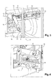
- the figures 2 , 3 and 4 represent the housing 2 according to one embodiment of the invention when a compartment 3 is in the closed position of the tubing 5.
- the figure 2 illustrates a compartment 3 of the housing 2 in the closed position of the tubing 5, the compartment door 3 open.
- the compartment 3 comprises a receiving means in which is inserted a clamp 8 which compresses the tubing 5 so as to interrupt the flow of fluid therein.
- the tubing 5 is typically made of a flexible tube. It is engaged in a window 9 formed in the clamp 8. In the closed position, the pipe 5 is located in the region of the window 9 which has a smaller dimension than the diameter of the pipe 5 so that it is pinch and no longer allows the flow of fluid.
- the receiving means consists of a movable slide 11 which moves the clamp 8 between a closed position of the pipe 5 and an opening position of the pipe 5.
- Spans 12 provided in the compartment 3 to guide the slide 11 in its movement and resilient biasing means urge the slide 11 in the closed position of the tubing 5.
- the elastic return means consist of helicoidal springs 13.
- a means for controlling the movement of the slide 11 is provided in each of the compartments 3 of the casing 2.
- This movable control means comprises a lever 14 pivoting on an axis 15 illustrated in FIG. figure 2 .
- the lever 14 can move between an inactive position and an active position under the control of an electromagnet 16.
- the inactive position is an inclined position, as shown in FIGS. figures 2 and 3 , in which the slide 11 is held in the closed position of the clamp 8 by the springs 13.
- the active position is substantially vertical, as shown in FIG. figure 5 , in which the lever 14 pushes the slide 11 to the open position of the clamp 8 against the force exerted by the springs 13.
- the compartment 3 comprises a door 17 shown open, allowing access to the interior of the housing 2. It is further provided with locking means which ensure the locking of the door 17 in the closed position. These means comprise two movable bolts 18 which ensure the opening and closing of the door 17. A locking member 19 movable between a locking and unlocking position is also provided. The locking means also comprise an elastic return device 21 urging the locking member 19 in the locked position of the door 17.
- the lever 14 is arranged on the door 17 so as to cooperate with the locking member 19.
- the lever 14 exerts a constraint on the locking member 19 and keeps it in the unlocked position against the force exerted by the return device 21.
- the lever 14 By moving to its active position, the lever 14 decreases the stress exerted on the locking member 19 which moves in the locking position under the action of the return device 21.
- the drawer 11 is pushed at the same time into position 5, the door 17 of the compartment 3 is locked when the tubing 5 is passing. Access to the interior of compartment 3 is then impossible, which makes it possible to secure the administration of the fluid.
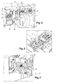
- the figure 3 illustrates a compartment 3 of the housing 2 whose door 17 is shown closed.
- the lever 14 is in the inactive position so that the clamp 8 of the slide 11 is held in the closed position of the tubing 5 by the elastic return means.
- the locking member 19 is in the unlocking position, the door 17 of the compartment 3 can therefore be opened by an operator by simply actuating the bolts 18.
- the figure 4 represents the locking means of the closed door 17 in the unlocked position.
- the lever 14 in the inactive position keeps the locking member 19 in the unlocked position, against the force exerted by the return device 21. In this position, the locking member 19 allows the bolts 18 to move towards one another. other and the opening of the door 17.
- the elastic return device 21, as shown in the embodiment of the figures 4 and 7 consists of a spring.
- FIGS 5, 6 and 7 illustrate the case 2 according to one embodiment of the invention when the compartment 3 is in the open position of the tublure.
- the figure 5 represents a compartment 3 whose door 17 is closed in the locked position, the clamp 8 in the open position of the tubing 5.
- the lever 14 is in the active position and exerts a pressure on the slide 11 so as to maintain it in position opening of the tubing 5, against the force of the springs 13. The fluid can thus flow in the tubing 5 and be administered to the patient.
- the figure 6 represents the drawer 11 of a compartment 3 holding the clamp 8 in the open position of the tubing 5 against the force exerted by the springs 13.
- the tubing 5 engaged in the clamp 8 is located in the region of the window 9 which has a dimension greater than the diameter of the pipe 5. This is not compressed and can circulate the fluid.
- the figure 7 represents the closed door 17 in the locked position.
- the locking member 19, released from the stress exerted by the lever 14, is held in the locking position under the bias of the return device 21. In this position, a part of the locking member 19 is embedded between the two bolts 18 making them immobile and thus blocking the opening of the door 17. Access to the interior of the compartment 3 is impossible, which secures the administration of the fluid.
- the pump 7 which embeds a programmable control electronics of the position of each of the closure clamps 8.
- electronic control means for example a microprocessor with a ROM and / or RAM, an input and output interface.
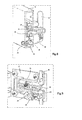
- FIG. 8 and 9 illustrate a particular embodiment of a door 17 of a compartment 3 comprising an unlocking member 22 for unlocking the door 17, whatever the position of closing or opening of the tubing 5 in which the clamp 8 of the compartment 3.
- This unlocking member 22 comprises a fork 23 pivoting about an axis 24 and a first end of which has a push button 25 projecting from the outer face of the door 17 (FIG. figure 8 ).
- a second end 26 of the fork 23 opposite the push button 25 comes into contact with the locking member 19 so as to be able to exert a pressure thereon against the return device 21 elastic.
- Pressure exerted on the push button 25, for example by an operator, causes the fork 23 to pivot about the axis 24 so that the second end 26 exerts a pressure on the locking member 19.
- This pressure causes the moving the locking member 19 from its locking position to its unlocking position, releasing the actuation of the bolts 18 ( figure 9 ).
- the displacement of the locking member 19 is independent of the active or inactive position in which the lever 14 presents itself.
- an operator can manually unlock the door 17 and open it, for example in a situation of emergency, to access the interior of the compartment 3 that the clamp 8 is in the closed position or opening of the tubing 5.
- each of the doors 17 of the housing 2 may be provided with the unlocking member 22 .
- an operator When it is desired to use the multi-channel infusion line 1 to sequentially and automatically administer different medical substances to a patient, an operator first opens the doors 17 of each of the compartments 3 to give free access to the drawer. 11.
- the clamps 8, each provided with a tubing 5 connected to a pocket 4, are inserted into the drawer 11 of each compartment 3.
- the springs 13 hold the drawers 11 in the closed position of the clamp 8 and prohibit the circulation fluid.
- the doors 17 of the compartments 3 are then closed by actuating the bolts 18.
- the operator then enters the infusion parameters by the pump 7, that is to say, order of infusion of the bags, flow rate of each bag, etc.
- the means for controlling the displacement of the slide 11 of a compartment 3 associated with a fluid to be delivered actuates the electromagnet 16 of the corresponding compartment 3. This actuates the movement of the lever 14 from its inactive position to its active position. The lever 14 then exerts pressure on the slide 11 which moves against the force of the springs 13 in the open position of the clamp 8. The tubing 5 held in the compartment 3 remains stationary while the clamp 8 moves so as to that the window 9 of the clamp 8 passes from a compression position of the tubing 5 to a position where it releases the tubing 5. This then allows the fluid contained in the bag 4 to circulate for administration to the patient.
- the displacement of the lever 14 in the active position releases the stress on the locking member 19 of the door 17.
- the locking member 19, biased by the return device 21, is interposed between the bolts 18 so as to immobilize them, thus locking the door 17 and the access to the tubing 5 in the pass phase.
- the detection device of the compartment 3 detects the end of the flow of drops indicating that the medical substance contained in the bag 4 has been totally injected into the patient. Ways control of the movement of the slide 11 actuate the lever 14 which returns to the inactive position. The slide 11 then returns to the closed position of the tubing 5 and the locking member 19 moves to its unlocked position. The door 17 can thus be opened by an operator.
- the means for controlling the displacement of the drawer 11 of the compartment 3 of the second fluid to be injected actuates the electromagnet 16 of the corresponding compartment 3.
- the lever 14 associated moves in the active position causing the locking of the door 17 and the displacement of the clamp 8 in the open position of the tubing 5.
- the electromagnet 16 actuates the lever 14 which pivots and returns to its inactive position.
- the drawer 11 returns to the closed position of the tubing 5 and the door 17 is again unlocked.
- an electromagnet 16 of a compartment 3 associated with a fluid Rinsing action activates the opening of the corresponding tubing 5 to deliver a predefined dose of rinsing fluid.
- This predefined dose of fluid can be calculated from the section and the length of the main tubing 6 to be rinsed.
- the rinsing time can be calculated according to the flow rate used.
- the multi-channel infusion line 1 is inexpensive and allows secure and automatic sequential administration of different fluids to a patient. It goes without saying that the invention is not limited to the embodiments and use of the infusion line 1 described above as an example, it encompasses all variants.
Applications Claiming Priority (1)
| Application Number | Priority Date | Filing Date | Title |
|---|---|---|---|
| FR1157255A FR2978919B1 (fr) | 2011-08-09 | 2011-08-09 | Boitier multivoies pilote |
Publications (1)
| Publication Number | Publication Date |
|---|---|
| EP2556854A1 true EP2556854A1 (de) | 2013-02-13 |
Family
ID=46603813
Family Applications (1)
| Application Number | Title | Priority Date | Filing Date |
|---|---|---|---|
| EP20120179690 Withdrawn EP2556854A1 (de) | 2011-08-09 | 2012-08-08 | Mehrweg-Infusionsleitung |
Country Status (2)
| Country | Link |
|---|---|
| EP (1) | EP2556854A1 (de) |
| FR (1) | FR2978919B1 (de) |
Cited By (4)
| Publication number | Priority date | Publication date | Assignee | Title |
|---|---|---|---|---|
| CN105771030A (zh) * | 2016-05-18 | 2016-07-20 | 广东工业大学 | 一种自动输液器 |
| CN106512131A (zh) * | 2016-10-28 | 2017-03-22 | 杭州国辰机器人科技有限公司 | 一种输液瓶换位单元及遥控更换输液瓶的输液装置 |
| EP3328466A4 (de) * | 2015-07-31 | 2019-05-01 | Smiths Medical ASD, Inc. | Infusionsleitungsklemmensysteme für infusionspumpen |
| FR3137297A1 (fr) * | 2022-06-29 | 2024-01-05 | Vygon | Contrôle de l’administration de médicaments par voie intraveineuse |
Citations (8)
| Publication number | Priority date | Publication date | Assignee | Title |
|---|---|---|---|---|
| US4559036A (en) * | 1983-12-14 | 1985-12-17 | Wunsch Richard E | Apparatus for controlling administration of multiple intravenous solutions and medications |
| EP0184918A2 (de) * | 1984-11-29 | 1986-06-18 | Minnesota Mining And Manufacturing Company | System für die intravenöse Verabreichung vielfältiger Lösungen |
| US5207642A (en) * | 1987-08-07 | 1993-05-04 | Baxter International Inc. | Closed multi-fluid delivery system and method |
| DE4440987A1 (de) * | 1993-11-18 | 1995-05-24 | Minnesota Mining & Mfg | Kardioplegie-Applikationssystem und -verfahren |
| WO1998056453A1 (en) * | 1997-06-12 | 1998-12-17 | Abbott Laboratories | Pump with anti-free flow feature |
| US20020165503A1 (en) * | 2001-05-04 | 2002-11-07 | Morris Matthew G. | Medical instrument flow stop interface |
| US20030181866A1 (en) * | 2002-03-21 | 2003-09-25 | Kent Abrahamson | Pump and tube set thereof |
| DE102004010062B3 (de) * | 2004-03-02 | 2005-09-08 | Drägerwerk AG | Vorrichtung zur Dosierung von Substanzen |
-
2011
- 2011-08-09 FR FR1157255A patent/FR2978919B1/fr active Active
-
2012
- 2012-08-08 EP EP20120179690 patent/EP2556854A1/de not_active Withdrawn
Patent Citations (8)
| Publication number | Priority date | Publication date | Assignee | Title |
|---|---|---|---|---|
| US4559036A (en) * | 1983-12-14 | 1985-12-17 | Wunsch Richard E | Apparatus for controlling administration of multiple intravenous solutions and medications |
| EP0184918A2 (de) * | 1984-11-29 | 1986-06-18 | Minnesota Mining And Manufacturing Company | System für die intravenöse Verabreichung vielfältiger Lösungen |
| US5207642A (en) * | 1987-08-07 | 1993-05-04 | Baxter International Inc. | Closed multi-fluid delivery system and method |
| DE4440987A1 (de) * | 1993-11-18 | 1995-05-24 | Minnesota Mining & Mfg | Kardioplegie-Applikationssystem und -verfahren |
| WO1998056453A1 (en) * | 1997-06-12 | 1998-12-17 | Abbott Laboratories | Pump with anti-free flow feature |
| US20020165503A1 (en) * | 2001-05-04 | 2002-11-07 | Morris Matthew G. | Medical instrument flow stop interface |
| US20030181866A1 (en) * | 2002-03-21 | 2003-09-25 | Kent Abrahamson | Pump and tube set thereof |
| DE102004010062B3 (de) * | 2004-03-02 | 2005-09-08 | Drägerwerk AG | Vorrichtung zur Dosierung von Substanzen |
Cited By (4)
| Publication number | Priority date | Publication date | Assignee | Title |
|---|---|---|---|---|
| EP3328466A4 (de) * | 2015-07-31 | 2019-05-01 | Smiths Medical ASD, Inc. | Infusionsleitungsklemmensysteme für infusionspumpen |
| CN105771030A (zh) * | 2016-05-18 | 2016-07-20 | 广东工业大学 | 一种自动输液器 |
| CN106512131A (zh) * | 2016-10-28 | 2017-03-22 | 杭州国辰机器人科技有限公司 | 一种输液瓶换位单元及遥控更换输液瓶的输液装置 |
| FR3137297A1 (fr) * | 2022-06-29 | 2024-01-05 | Vygon | Contrôle de l’administration de médicaments par voie intraveineuse |
Also Published As
| Publication number | Publication date |
|---|---|
| FR2978919B1 (fr) | 2014-09-12 |
| FR2978919A1 (fr) | 2013-02-15 |
Similar Documents
| Publication | Publication Date | Title |
|---|---|---|
| EP1589926B1 (de) | Vorrichtung und verfahren zur extemporierten präparation einer sterilen flüssigen dosis | |
| EP0846008B1 (de) | Vorrichtung zur kontinuierlichen injektion | |
| EP2296733B1 (de) | Vorrichtung zur injektion einer medizinischen flüssigkeit zur medizinischen verwendung | |
| EP2556854A1 (de) | Mehrweg-Infusionsleitung | |
| EP2089082A1 (de) | Vorrichtung zur steuerung des öffnens und schliessens einer klammer bei einer verdrängerpumpe | |
| EP2590699B1 (de) | Spendevorrichtung für ein fluides produkt | |
| EP2774650A1 (de) | Stecker-Schutzdeckel-Einheit | |
| FR2753235A1 (fr) | Pompe peristaltique portable | |
| WO1998011350A1 (fr) | Pompe peristaltique miniature | |
| LU87791A1 (fr) | Sonde uretrale installee a demeure comportant une valve d'evacuation commandee magnetiquement,et procede | |
| WO2013178951A1 (fr) | Dispositif de distribution de produit fluide | |
| EP2854914A1 (de) | Vorrichtung zur ausgabe eines flüssigprodukts | |
| EP0968682A1 (de) | Blutentnahmevorrichtung für ein vakuum evakuiertes Röhrchen | |
| WO2013175120A1 (fr) | Dispositif de distribution de produit fluide. | |
| EP1034772A1 (de) | Vorrichtung zum Übertragen einer in einem Flacon enthaltenen Substanz in einen Beutel der eine Lösung enthält | |
| WO2002045649A1 (fr) | Dispositif de reconstitution notamment pour le melange de substances dans le domaine medical | |
| FR2635009A2 (fr) | Dispositif de retenue d'une ampoule de seringue hypodermique dans son boitier | |
| EP1023914B1 (de) | Vorrichtung zum Abklemmen eines biegsamen Schlauches | |
| FR2788431A1 (fr) | Embout de transfert | |
| FR2753103A1 (fr) | Pompe peristaltique miniature a usage medical | |
| EP0336853A1 (de) | Schutzkaste einer Anschlussstelle für medizinische Zwecke | |
| FR2909645A1 (fr) | Dispositif de distribution de produit fluide | |
| CN112512620A (zh) | 包括夹持装置的输液装置 | |
| WO2023209018A1 (fr) | Dispositif d'administration de médicament transdermique | |
| EP1661589A1 (de) | Beutelanordnung zum automatischen Entnehmen von biologischen Fluidproben |
Legal Events
| Date | Code | Title | Description |
|---|---|---|---|
| PUAI | Public reference made under article 153(3) epc to a published international application that has entered the european phase |
Free format text: ORIGINAL CODE: 0009012 |
|
| AK | Designated contracting states |
Kind code of ref document: A1 Designated state(s): AL AT BE BG CH CY CZ DE DK EE ES FI FR GB GR HR HU IE IS IT LI LT LU LV MC MK MT NL NO PL PT RO RS SE SI SK SM TR |
|
| AX | Request for extension of the european patent |
Extension state: BA ME |
|
| 17P | Request for examination filed |
Effective date: 20130807 |
|
| RBV | Designated contracting states (corrected) |
Designated state(s): AL AT BE BG CH CY CZ DE DK EE ES FI FR GB GR HR HU IE IS IT LI LT LU LV MC MK MT NL NO PL PT RO RS SE SI SK SM TR |
|
| 17Q | First examination report despatched |
Effective date: 20131007 |
|
| RIC1 | Information provided on ipc code assigned before grant |
Ipc: A61M 39/28 20060101ALI20150506BHEP Ipc: A61M 5/168 20060101ALI20150506BHEP Ipc: A61M 5/14 20060101AFI20150506BHEP |
|
| GRAP | Despatch of communication of intention to grant a patent |
Free format text: ORIGINAL CODE: EPIDOSNIGR1 |
|
| INTG | Intention to grant announced |
Effective date: 20150820 |
|
| STAA | Information on the status of an ep patent application or granted ep patent |
Free format text: STATUS: THE APPLICATION IS DEEMED TO BE WITHDRAWN |
|
| 18D | Application deemed to be withdrawn |
Effective date: 20160105 |