EP2556636B1 - Method and apparatus for constructing very high throughput long training field sequences - Google Patents
Method and apparatus for constructing very high throughput long training field sequences Download PDFInfo
- Publication number
- EP2556636B1 EP2556636B1 EP11716704.9A EP11716704A EP2556636B1 EP 2556636 B1 EP2556636 B1 EP 2556636B1 EP 11716704 A EP11716704 A EP 11716704A EP 2556636 B1 EP2556636 B1 EP 2556636B1
- Authority
- EP
- European Patent Office
- Prior art keywords
- ltf
- tones
- papr
- ltf sequence
- preamble
- Prior art date
- Legal status (The legal status is an assumption and is not a legal conclusion. Google has not performed a legal analysis and makes no representation as to the accuracy of the status listed.)
- Active
Links
- 238000000034 method Methods 0.000 title claims description 40
- 238000012549 training Methods 0.000 title claims description 36
- 230000005540 biological transmission Effects 0.000 claims description 61
- 238000004891 communication Methods 0.000 claims description 31
- 238000004590 computer program Methods 0.000 claims description 9
- 238000012545 processing Methods 0.000 description 27
- 230000000295 complement effect Effects 0.000 description 20
- ZXVONLUNISGICL-UHFFFAOYSA-N 4,6-dinitro-o-cresol Chemical compound CC1=CC([N+]([O-])=O)=CC([N+]([O-])=O)=C1O ZXVONLUNISGICL-UHFFFAOYSA-N 0.000 description 14
- 238000005516 engineering process Methods 0.000 description 14
- 230000006870 function Effects 0.000 description 9
- 230000008901 benefit Effects 0.000 description 5
- 239000000969 carrier Substances 0.000 description 5
- 238000010586 diagram Methods 0.000 description 5
- 230000001413 cellular effect Effects 0.000 description 4
- 238000001514 detection method Methods 0.000 description 4
- 239000000835 fiber Substances 0.000 description 4
- 238000005457 optimization Methods 0.000 description 4
- 238000013459 approach Methods 0.000 description 3
- 238000013461 design Methods 0.000 description 3
- 239000011159 matrix material Substances 0.000 description 3
- 230000003287 optical effect Effects 0.000 description 3
- 239000005022 packaging material Substances 0.000 description 2
- 230000010363 phase shift Effects 0.000 description 2
- 230000008569 process Effects 0.000 description 2
- 230000009467 reduction Effects 0.000 description 2
- 238000005070 sampling Methods 0.000 description 2
- 230000008685 targeting Effects 0.000 description 2
- 238000012546 transfer Methods 0.000 description 2
- 101100458289 Drosophila melanogaster msps gene Proteins 0.000 description 1
- 230000008859 change Effects 0.000 description 1
- 239000003795 chemical substances by application Substances 0.000 description 1
- 238000012937 correction Methods 0.000 description 1
- 230000008878 coupling Effects 0.000 description 1
- 238000010168 coupling process Methods 0.000 description 1
- 238000005859 coupling reaction Methods 0.000 description 1
- 125000004122 cyclic group Chemical group 0.000 description 1
- 230000000977 initiatory effect Effects 0.000 description 1
- 238000010295 mobile communication Methods 0.000 description 1
- 238000012986 modification Methods 0.000 description 1
- 230000004048 modification Effects 0.000 description 1
- 238000005192 partition Methods 0.000 description 1
- 230000002093 peripheral effect Effects 0.000 description 1
- 230000008054 signal transmission Effects 0.000 description 1
Images


Classifications
-
- H—ELECTRICITY
- H04—ELECTRIC COMMUNICATION TECHNIQUE
- H04L—TRANSMISSION OF DIGITAL INFORMATION, e.g. TELEGRAPHIC COMMUNICATION
- H04L27/00—Modulated-carrier systems
- H04L27/26—Systems using multi-frequency codes
-
- H—ELECTRICITY
- H04—ELECTRIC COMMUNICATION TECHNIQUE
- H04L—TRANSMISSION OF DIGITAL INFORMATION, e.g. TELEGRAPHIC COMMUNICATION
- H04L27/00—Modulated-carrier systems
- H04L27/26—Systems using multi-frequency codes
- H04L27/2601—Multicarrier modulation systems
- H04L27/2602—Signal structure
- H04L27/261—Details of reference signals
- H04L27/2613—Structure of the reference signals
- H04L27/26132—Structure of the reference signals using repetition
-
- H—ELECTRICITY
- H04—ELECTRIC COMMUNICATION TECHNIQUE
- H04L—TRANSMISSION OF DIGITAL INFORMATION, e.g. TELEGRAPHIC COMMUNICATION
- H04L27/00—Modulated-carrier systems
- H04L27/26—Systems using multi-frequency codes
- H04L27/2601—Multicarrier modulation systems
- H04L27/2614—Peak power aspects
- H04L27/2618—Reduction thereof using auxiliary subcarriers
-
- H—ELECTRICITY
- H04—ELECTRIC COMMUNICATION TECHNIQUE
- H04L—TRANSMISSION OF DIGITAL INFORMATION, e.g. TELEGRAPHIC COMMUNICATION
- H04L27/00—Modulated-carrier systems
- H04L27/26—Systems using multi-frequency codes
- H04L27/2601—Multicarrier modulation systems
- H04L27/2614—Peak power aspects
- H04L27/262—Reduction thereof by selection of pilot symbols
-
- H—ELECTRICITY
- H04—ELECTRIC COMMUNICATION TECHNIQUE
- H04L—TRANSMISSION OF DIGITAL INFORMATION, e.g. TELEGRAPHIC COMMUNICATION
- H04L27/00—Modulated-carrier systems
- H04L27/26—Systems using multi-frequency codes
- H04L27/2601—Multicarrier modulation systems
- H04L27/2614—Peak power aspects
- H04L27/2621—Reduction thereof using phase offsets between subcarriers
-
- H—ELECTRICITY
- H04—ELECTRIC COMMUNICATION TECHNIQUE
- H04W—WIRELESS COMMUNICATION NETWORKS
- H04W28/00—Network traffic management; Network resource management
- H04W28/02—Traffic management, e.g. flow control or congestion control
- H04W28/06—Optimizing the usage of the radio link, e.g. header compression, information sizing, discarding information
- H04W28/065—Optimizing the usage of the radio link, e.g. header compression, information sizing, discarding information using assembly or disassembly of packets
-
- H—ELECTRICITY
- H04—ELECTRIC COMMUNICATION TECHNIQUE
- H04W—WIRELESS COMMUNICATION NETWORKS
- H04W52/00—Power management, e.g. TPC [Transmission Power Control], power saving or power classes
- H04W52/04—TPC
- H04W52/30—TPC using constraints in the total amount of available transmission power
- H04W52/32—TPC of broadcast or control channels
- H04W52/325—Power control of control or pilot channels
-
- H—ELECTRICITY
- H04—ELECTRIC COMMUNICATION TECHNIQUE
- H04B—TRANSMISSION
- H04B7/00—Radio transmission systems, i.e. using radiation field
- H04B7/02—Diversity systems; Multi-antenna system, i.e. transmission or reception using multiple antennas
- H04B7/04—Diversity systems; Multi-antenna system, i.e. transmission or reception using multiple antennas using two or more spaced independent antennas
- H04B7/0413—MIMO systems
-
- H—ELECTRICITY
- H04—ELECTRIC COMMUNICATION TECHNIQUE
- H04W—WIRELESS COMMUNICATION NETWORKS
- H04W84/00—Network topologies
- H04W84/02—Hierarchically pre-organised networks, e.g. paging networks, cellular networks, WLAN [Wireless Local Area Network] or WLL [Wireless Local Loop]
- H04W84/10—Small scale networks; Flat hierarchical networks
- H04W84/12—WLAN [Wireless Local Area Networks]
Definitions
- Certain aspects of the present disclosure generally relate to wireless communications and, more particularly, to a method and apparatus for constructing a long training field (LTF) sequence as a part of transmission preamble for Very High Throughput (VHT) wireless systems.
- LTF long training field
- VHT Very High Throughput
- VHT Very High Throughput
- One of the enabling technologies for the VHT 5 GHz specification is a wider channel bandwidth, which bonds two 40MHz channels for 80MHz bandwidth therefore doubling the physical layer (PHY) data rate with negligible increase in cost compared to the IEEE 802.11n standard.
- a VHT Long Training Field is a part of a transmission preamble, and can be utilized at a receiver side to estimate characteristics of underlying multiple-input multiple output (MIMO) wireless channel.
- Methods and apparatus are proposed in the present disclosure for constructing the VHT-LTF sequence, while providing a low peak-to-average power ratio (PAPR) at a transmitting node.
- PAPR peak-to-average power ratio
- WAHYUL AMIEN SYAFEI ET AL "A design of next generation Gigabit MIMO wireless LAN system", THE 12TH INTERNATIONAL CONFERENCE ON ADVANCED COMMUNICATION TECHNOLOGY (ICACT), 2010, IEEE, PISCATAWAY, NJ, USA, 7 February 2010 (2010-02-07), pages 941-946, XP031653679 , discloses a IEEE 802.11ac preamble structure ensuring backward compatiblity to IEEE 802.11a/n systems.
- a VHT-LTF is constructed using two times duplication of the 802.11n HT-LTF followed by phase shift and phase rotation.
- Certain aspects of the present disclosure support a method for wireless communications.
- the method generally includes constructing a long training field (LTF) sequence of a preamble by combining a plurality of interpolating sequences with LTF tone values associated with at least one of the IEEE 802.1 In standard or the IEEE 802.11 a standard, wherein the LTF tone values cover at least a portion of bandwidth of a first size, and each of the LTF tone values is repeated one or more times for different subcarriers, rotating phases of tones of the LTF sequence per bandwidth of the first size in an effort to reduce a peak-to-average power ratio (PAPR) during a transmission of the LTF sequence, and replacing tones of the LTF sequence at pilot locations with a defined stream of values chosen in an effort to reduce the PAPR.
- LTF long training field
- the apparatus generally includes a first circuit configured to construct a long training field (LTF) sequence of a preamble by combining a plurality of interpolating sequences with LTF tone values associated with at least one of the IEEE 802.1 In standard or the IEEE 802.11a standard, wherein the LTF tone values cover at least a portion of bandwidth of a first size, and each of the LTF tone values is repeated one or more times for different subcarriers, a second circuit configured to rotate phases of tones of the LTF sequence per bandwidth of the first size in an effort to reduce a peak-to-average power ratio (PAPR) during a transmission of the LTF sequence, and a third circuit configured to replace tones of the LTF sequence at pilot locations with a defined stream of values chosen in an effort to reduce the PAPR.
- LTF long training field
- the apparatus generally includes means for constructing a long training field (LTF) sequence of a preamble by combining a plurality of interpolating sequences with LTF tone values associated with at least one of the IEEE 802.11n standard or the IEEE 802.11 a standard, wherein the LTF tone values cover at least a portion of bandwidth of a first size, and each of the LTF tone values is repeated one or more times for different subcarriers, means for rotating phases of tones of the LTF sequence per bandwidth of the first size in an effort to reduce a peak-to-average power ratio (PAPR) during a transmission of the LTF sequence, and means for replacing tones of the LTF sequence at pilot locations with a defined stream of values chosen in an effort to reduce the PAPR.
- LTF long training field
- the computer-program product includes a computer-readable medium comprising instructions executable to construct a long training field (LTF) sequence of a preamble by combining a plurality of interpolating sequences with LTF tone values associated with at least one of the IEEE 802.1 In standard or the IEEE 802.11 a standard, wherein the LTF tone values cover at least a portion of bandwidth of a first size, and each of the LTF tone values is repeated one or more times for different subcarriers, rotate phases of tones of the LTF sequence per bandwidth of the first size in an effort to reduce a peak-to-average power ratio (PAPR) during a transmission of the LTF sequence, and replace tones of the LTF sequence at pilot locations with a defined stream of values chosen in an effort to reduce the PAPR.
- LTF long training field
- the access point generally includes at least one antenna, a first circuit configured to construct a long training field (LTF) sequence of a preamble by combining a plurality of interpolating sequences with LTF tone values associated with at least one of the IEEE 802.1 In standard or the IEEE 802.11a standard, wherein the LTF tone values cover at least a portion of bandwidth of a first size, and each of the LTF tone values is repeated one or more times for different subcarriers, a second circuit configured to rotate phases of tones of the LTF sequence per bandwidth of the first size in an effort to reduce a peak-to-average power ratio (PAPR) during a transmission of the LTF sequence, a third circuit configured to replace tones of the LTF sequence at pilot locations with a defined stream of values chosen in an effort to reduce the PAPR, and a transmitter configured to transmit via the at least one antenna the LTF sequence using a bandwidth of a second size.
- LTF long training field
- the techniques described herein may be used for various broadband wireless communication systems, including communication systems that are based on an orthogonal multiplexing scheme.
- Examples of such communication systems include Orthogonal Frequency Division Multiple Access (OFDMA) systems, Single-Carrier Frequency Division Multiple Access (SC-FDMA) systems, and so forth.
- OFDMA orthogonal Frequency Division Multiple Access
- SC-FDMA Single-Carrier Frequency Division Multiple Access
- An OFDMA system utilizes orthogonal frequency division multiplexing (OFDM), which is a modulation technique that partitions the overall system bandwidth into multiple orthogonal sub-carriers. These sub-carriers may also be called tones, bins, etc. With OFDM, each sub-carrier may be independently modulated with data.
- OFDM orthogonal frequency division multiplexing
- An SC-FDMA system may utilize interleaved FDMA (IFDMA) to transmit on sub-carriers that are distributed across the system bandwidth, localized FDMA (LFDMA) to transmit on a block of adjacent sub-carriers, or enhanced FDMA (EFDMA) to transmit on multiple blocks of adjacent sub-carriers.
- IFDMA interleaved FDMA
- LFDMA localized FDMA
- EFDMA enhanced FDMA
- modulation symbols are sent in the frequency domain with OFDM and in the time domain with SC-FDMA.
- a node implemented in accordance with the teachings herein may comprise an access point or an access terminal.
- An access point may comprise, be implemented as, or known as NodeB, Radio Network Controller (“RNC”), eNodeB, Base Station Controller (“BSC”), Base Transceiver Station (“BTS”), Base Station (“BS”), Transceiver Function (“TF”), Radio Router, Radio Transceiver, Basic Service Set (“BSS”), Extended Service Set (“ESS”), Radio Base Station (“RBS”), or some other terminology.
- RNC Radio Network Controller
- BSC Base Station Controller
- BTS Base Transceiver Station
- BS Base Station
- Transceiver Function Transceiver Function
- Radio Router Radio Transceiver
- BSS Basic Service Set
- ESS Extended Service Set
- RBS Radio Base Station
- An access terminal may comprise, be implemented as, or known as an access terminal, a subscriber station, a subscriber unit, a mobile station, a remote station, a remote terminal, a user terminal, a user agent, a user device, user equipment, or some other terminology.
- an access terminal may comprise a cellular telephone, a cordless telephone, a Session Initiation Protocol ("SIP”) phone, a wireless local loop (“WLL”) station, a personal digital assistant (“PDA”), a handheld device having wireless connection capability, or some other suitable processing device connected to a wireless modem.
- SIP Session Initiation Protocol
- WLL wireless local loop
- PDA personal digital assistant
- a phone e.g., a cellular phone or smart phone
- a computer e.g., a laptop
- a portable communication device e.g., a portable computing device (e.g., a personal data assistant), an entertainment device (e.g., a music or video device, or a satellite radio), a global positioning system device, a headset, a sensor or any other suitable device that is configured to communicate via a wireless or wired medium.
- the node is a wireless node.
- Such wireless node may provide, for example, connectivity for or to a network (e.g., a wide area network such as the Internet or a cellular network) via a wired or wireless communication link.
- the wireless network 100 is shown with several wireless nodes, generally designated as nodes 110 and 120. Each wireless node is capable of receiving and/or transmitting.
- receiving node may be used to refer to a node that is receiving and the term “transmitting node” may be used to refer to a node that is transmitting. Such a reference does not imply that the node is incapable of performing both transmit and receive operations.
- the wireless network 100 may represent the IEEE 802.11 Wide Local Area Network (WLAN) utilizing the Very High Throughput (VHT) protocol for signal transmissions utilizing a carrier frequency of 5GHz (i.e., the IEEE 802.11ac specification) or utilizing a carrier frequency of 60GHz (i.e., the IEEE 802.11ad specification) targeting aggregate throughputs larger than 1 Gigabits per second.
- VHT 5GHz specification may utilize a wider channel bandwidth, which may comprise two 40MHz channels for achieving 80MHz bandwidth, therefore doubling the PHY data rate with negligible increase in cost compared to the IEEE 802.1 In standard.
- an access point is used to designate a transmitting node and the term “access terminal” is used to designate a receiving node for downlink communications
- the term “access point” is used to designate a receiving node
- the term “access terminal” is used to designate a transmitting node for uplink communications.
- an access point may be referred to as a base station, a base transceiver station, a station, a terminal, a node, an access terminal acting as an access point, or some other suitable terminology.
- An access terminal may be referred to as a user terminal, a mobile station, a subscriber station, a station, a wireless device, a terminal, a node or some other suitable terminology.
- a user terminal a mobile station, a subscriber station, a station, a wireless device, a terminal, a node or some other suitable terminology.
- the various concepts described throughout this disclosure are intended to apply to all suitable wireless nodes regardless of their specific nomenclature.
- the wireless network 100 may support any number of access points distributed throughout a geographic region to provide coverage for access terminals 120.
- a system controller 130 may be used to provide coordination and control of the access points, as well as access to other networks (e.g., Internet) for the access terminals 120.
- one access point 110 is shown.
- An access point is generally a fixed terminal that provides backhaul services to access terminals in the geographic region of coverage; however, the access point may be mobile in some applications.
- a very high throughput long training field (VHT-LTF) sequence may be constructed within a VHT preamble transmitted to one or more of the access terminals 120 such that to achieve a preferred level of peak-to-average power ratio (PAPR) at a transmitter of the access point 110.
- An access terminal which may be fixed or mobile, utilizes the backhaul services of an access point or engages in peer-to-peer communications with other access terminals. Examples of access terminals include a telephone (e.g., cellular telephone), a laptop computer, a desktop computer, a Personal Digital Assistant (PDA), a digital audio player (e.g., MP3 player), a camera, a game console or any other suitable wireless node.
- PDA Personal Digital Assistant
- MP3 player digital audio player
- One or more access terminals 120 may be equipped with multiple antennas to enable certain functionality. With this configuration, multiple antennas at the access point 110 may be used to communicate with a multiple antenna access terminal to improve data throughput without additional bandwidth or transmit power. This may be achieved by splitting a high data rate signal at the transmitter into multiple lower rate data streams with different spatial signatures, thus enabling the receiver to separate these streams into multiple channels and properly combine the streams to recover the high rate data signal.
- the access point 110 may also be configured to support access terminals that do not support MIMO technology.
- This approach may allow older versions of access terminals (i.e., "legacy" terminals) to remain deployed in a wireless network, extending their useful lifetime, while allowing newer MIMO access terminals to be introduced as appropriate.
- OFDM Orthogonal Frequency Division Multiplexing
- CDMA Code Division Multiple Access
- TDMA Time Division Multiple Access
- suitable wireless technologies include, by way of example, Code Division Multiple Access (CDMA), Time Division Multiple Access (TDMA), or any other suitable wireless technology, or any combination of suitable wireless technologies.
- a CDMA system may implement with IS-2000, IS-95, IS-856, Wideband-CDMA (WCDMA) or some other suitable air interface standard.
- WCDMA Wideband-CDMA
- a TDMA system may implement Global System for Mobile Communications (GSM) or some other suitable air interface standard.
- GSM Global System for Mobile Communications
- FIG. 2 illustrates a conceptual block diagram illustrating an example of the signal processing functions of the Physical (PHY) layer.
- a TX data processor 202 may be used to receive data from the Media Access Control (MAC) layer and encode (e.g., Turbo code) the data to facilitate forward error correction (FEC) at the receiving node.
- the encoding process results in a sequence of code symbols that that may be blocked together and mapped to a signal constellation by the TX data processor 202 to produce a sequence of modulation symbols.
- the TX data processor 202 may generate a very high throughput long training field (VHT-LTF) sequence within a transmission VHT preamble such that to achieve a preferred level of PAPR.
- VHT-LTF very high throughput long training field
- the modulation symbols from the TX data processor 202 may be provided to an OFDM modulator 204.
- the OFDM modulator splits the modulation symbols into parallel streams. Each stream is then mapped to an OFDM subcarrier and then combined together using an Inverse Fast Fourier Transform (IFFT) to produce a time domain OFDM stream.
- IFFT Inverse Fast Fourier Transform
- a TX spatial processor 206 performs spatial processing on the OFDM stream. This may be accomplished by spatially precoding each OFDM and then providing each spatially precoded stream to a different antenna 208 via a transceiver 206. Each transmitter 206 modulates an RF carrier with a respective precoded stream for transmission over the wireless channel.
- each transceiver 206 receives a signal through its respective antenna 208.
- Each transceiver 206 may be used to recover the information modulated onto an RF carrier and provide the information to a RX spatial processor 210.
- the RX spatial processor 210 performs spatial processing on the information to recover any spatial streams destined for the wireless node 200.
- the spatial processing may be performed in accordance with Channel Correlation Matrix Inversion (CCMI), Minimum Mean Square Error (MMSE), Soft Interference Cancellation (SIC) or some other suitable technique. If multiple spatial streams are destined for the wireless node 200, they may be combined by the RX spatial processor 210.
- CCMI Channel Correlation Matrix Inversion
- MMSE Minimum Mean Square Error
- SIC Soft Interference Cancellation
- the stream (or combined stream) from the RX spatial processor 210 is provided to an OFDM demodulator 212.
- the OFDM demodulator 212 converts the stream (or combined stream) from time-domain to the frequency domain using a Fast Fourier Transform (FFT).
- the frequency domain signal comprises a separate stream for each subcarrier of the OFDM signal.
- the OFDM demodulator 212 recovers the data (i.e., modulation symbols) carried on each subcarrier and multiplexes the data into a stream of modulation symbols.
- a RX data processor 214 may be used to translate the modulation symbols back to the correct point in the signal constellation. Because of noise and other disturbances in the wireless channel, the modulation symbols may not correspond to an exact location of a point in the original signal constellation. The RX data processor 214 detects which modulation symbol was most likely transmitted by finding the smallest distance between the received point and the location of a valid symbol in the signal constellation. These soft decisions may be used, in the case of Turbo codes, for example, to compute a Log-Likelihood Ratio (LLR) of the code symbols associated with the given modulation symbols. The RX data processor 214 then uses the sequence of code symbol LLRs in order to decode the data that was originally transmitted before providing the data to the MAC layer.
- LLR Log-Likelihood Ratio
- FIG. 3 illustrates a conceptual diagram illustrating an example of a hardware configuration for a processing system in a wireless node.
- the processing system 300 may be implemented with a bus architecture represented generally by bus 302.
- the bus 302 may include any number of interconnecting buses and bridges depending on the specific application of the processing system 300 and the overall design constraints.
- the bus links together various circuits including a processor 304, machine-readable media 306 and a bus interface 308.
- the bus interface 308 may be used to connect a network adapter 310, among other things, to the processing system 300 via the bus 302.
- the network adapter 310 may be used to implement the signal processing functions of the PHY layer.
- an access terminal 110 see FIG.
- a user interface 312 (e.g., keypad, display, mouse, joystick, etc.) may also be connected to the bus.
- the bus 302 may also link various other circuits such as timing sources, peripherals, voltage regulators, power management circuits, and the like, which are well known in the art, and therefore, will not be described any further.
- the processor 304 is responsible for managing the bus and general processing, including the execution of software stored on the machine-readable media 306.
- the processor 304 may be implemented with one or more general-purpose and/or special-purpose processors. Examples include microprocessors, microcontrollers, DSP processors and other circuitry that can execute software.
- Software shall be construed broadly to mean instructions, data or any combination thereof, whether referred to as software, firmware, middleware, microcode, hardware description language, or otherwise.
- Machine-readable media may include, by way of example, RAM (Random Access Memory), flash memory, ROM (Read Only Memory), PROM (Programmable Read-Only Memory), EPROM (Erasable Programmable Read-Only Memory), EEPROM (Electrically Erasable Programmable Read-Only Memory), registers, magnetic disks, optical disks, hard drives, or any other suitable storage medium, or any combination thereof.
- the machine-readable media may be embodied in a computer-program product.
- the computer-program product may comprise packaging materials.
- the processor 304 may perform or direct operations 900 in FIG. 9 and/or other processes for the techniques described herein.
- the machine-readable media 306 is shown as part of the processing system 300 separate from the processor 304. However, as those skilled in the art will readily appreciate, the machine-readable media 306, or any portion thereof, may be external to the processing system 300.
- the machine-readable media 306 may include a transmission line, a carrier wave modulated by data, and/or a computer product separate from the wireless node, all which may be accessed by the processor 304 through the bus interface 308.
- the machine readable media 306, or any portion thereof may be integrated into the processor 304, such as the case may be with cache and/or general register files.
- the processing system 300 may be configured as a general-purpose processing system with one or more microprocessors providing the processor functionality and external memory providing at least a portion of the machine-readable media 306, all linked together with other supporting circuitry through an external bus architecture.
- the processing system 300 may be implemented with an ASIC (Application Specific Integrated Circuit) with the processor 304, the bus interface 308, the user interface 312 in the case of an access terminal), supporting circuitry (not shown), and at least a portion of the machine-readable media 306 integrated into a single chip, or with one or more FPGAs (Field Programmable Gate Array), PLDs (Programmable Logic Device), controllers, state machines, gated logic, discrete hardware components, or any other suitable circuitry, or any combination of circuits that can perform the various functionality described throughout this disclosure.
- FPGAs Field Programmable Gate Array
- PLDs Programmable Logic Device
- controllers state machines, gated logic, discrete hardware components, or any other suitable circuitry, or any combination of circuits that can perform the
- Certain aspects of the present disclosure support a method and apparatus for constructing a training sequence as a part of VHT transmission preamble such that a PAPR at a transmitting node can be sufficiently low.
- the training sequence may comprise a VHT-LTF sequence.
- FIG. 4 illustrates an example structure of a preamble 400 comprising a VHT-LTF sequence in accordance with certain aspects of the present disclosure.
- the preamble 400 may be transmitted from the access point 110 to one or more of the access terminals 120 in the wireless network 100 illustrated in FIG. 1 .
- the preamble 400 may be transmitted in accordance with IEEE 802.11ac specification or in accordance with IEEE 802.11ad specification.
- the preamble 400 may comprise an omni-legacy portion 402 and a precoded 802.11ac VHT portion 414.
- the legacy portion 402 may comprise: a Legacy Short Training Field (L-STF) 404, a Legacy Long Training Field 406, a Legacy Signal (L-SIG) field 408, and two OFDM symbols 410, 412 for Very High Throughput Signal fields type A (VHT-SIG-A fields).
- the VHT-SIG-A fields 410, 412 may be transmitted omni-directionally.
- the precoded 802.11ac VHT portion 414 may comprise: a Very High Throughput Short Training Field (VHT-STF) 416, a Very High Throughput Long Training Field 1 (VHT-LTF1) 418, Very High Throughput Long Training Fields (VHT-LTFs) 420, a Very High Throughput Signal field type B (VHT-SIG-B field 422), and a data packet 424.
- VHT-STF Very High Throughput Short Training Field
- VHT-LTF1 Very High Throughput Long Training Field 1
- VHT-LTFs Very High Throughput Long Training Fields
- VHT-SIG-B field 422 Very High Throughput Signal field type B
- the VHT-SIG-B field may comprise one OFDM symbol and may be transmitted precoded/beamformed.
- the VHT-LTF sequence 420 may allow each user to estimate a MIMO channel from all AP antennas to the user antennas. The user may utilize the estimated channel to perform effective interference nulling from MU-MIMO streams corresponding to other users.
- a novel structure of the VHT-LTF sequence 420 may be constructed in an effort to minimize (or at least reduce) PAPR at a transmitter of the AP.
- the VHT-LTF sequence may be constructed for 80MHz channel by using four 802.11 a LTF sequences in 20MHz sub-bands covered by a complementary sequence, wherein the complementary sequence may be equivalent to phase rotation on each of the 20MHz sub-bands.
- some additional tone values may be chosen in an effort to minimize (or at least reduce) the PAPR during transmission of the VHT-LTF sequence.
- interpolating sequences interp20Null , interp40Null, interp80ExtraL, interp80ExtraR may comprise extra tones to be chosen in an effort to minimize (or at least reduce) the PAPR, and [ c 1 c 2 c 3 c 4] may represent the complementary sequence.
- VHT-LTF sequences designed based on the VHT-LTF pattern from equation (1) may be obtained when transmitting VHT-LTF sequences designed based on the VHT-LTF pattern from equation (1).
- the VHT-LTF sequences constructed based on four 20MHz 802.11 a LTF sequences may provide improved PAPR results compared to VHT-LTF sequences constructed based on two 802.1 In LTF sequences in 40MHz sub-bands.
- phase rotation of upper 40MHz band may not result into PAPR reduction; the PAPR results may be even worse.
- the complementary sequences [1 1 1 -1] and [1 -1 1 1] may provide better PAPR results than the complementary sequences [1 1 -1 1] and [-1 1 1].
- phase rotation by 90 degrees of an odd or even 20MHz sub-band may not help in further PAPR reduction.
- the VHT-LTF sequences constructed for 80MHz channel bandwidth based on the pattern from equation (1) may provide preferred PAPR results for different non-oversampling and oversampling cases, if the VHT-LTFs comprise the interpolating sequences interp20Null, interp40Null, interp80ExtraL, interp80ExtraR and the rotation pattern [ c 1 c 2 c 3 c 4] as given in FIG. 5A .
- the label "with rotation” in FIG. 5A and in FIGS. 5B-5J that follows refers to the phase rotation of tones in upper 40MHz band by 90 degrees, while the label “4x TDI” refers to four times oversampling based on time-domain interpolation (TDI).
- Sampling rates of 80 Mega-samples per second (Msps) or 320Msps may be utilized, as illustrated in FIGS. 5A-5J .
- the VHT-LTF sequence may be constructed for transmission over 80MHz channel by using all 20MHz 802.11 a tones and 40MHz 802.11n tones.
- every tone that may be present in 20MHz 802.11a or in 40MHz 802.1 In may have the value of corresponding tone from the 20MHz LTF sequence or the 40MHz HT-LTF sequence.
- a complementary phase rotation sequence may be applied per 20MHz 802.11 a bandwidth (i.e., 802.11a tones may be rotated), and a few missing tones may be filled.
- the interpolating sequences interp40Null, interp80ExtraL, interp80ExtraR may comprise extra tones to be chosen in an effort to minimize (or at least reduce) the PAPR
- [ c 1 c 2 c 3 c 4] may represent the complementary phase rotation sequence.
- One advantage of the VHT-LTF pattern from equation (2) can be that there may be no need to store different values for existing 20MHz 802.11 a and 40MHz 802.1 In tones.
- a level of PAPR may be slightly higher than that of the VHT-LTF pattern from equation (1) because of less extra tones to be chosen in an effort to minimize (or at least reduce) the PAPR.
- PAPR results may be obtained when transmitting 80MHz VHT-LTF sequences designed based on the VHT-LTF pattern from equation (2). It can be observed that the VHT-LTF sequences based on the pattern from equation (2) may represent a subset of the previously generated VHT-LTF sequences based on the pattern from equation (1). Therefore, PAPR results of the VHT-LTF sequences constructed based on the pattern from equation (2) may not be better than PAPR results of the VHT-LTF sequences constructed based on the pattern from equation (1).
- the VHT-LTF sequences constructed for 80MHz channel bandwidth based on the pattern from equation (2) may provide preferred PAPR results for different non-oversampling and oversampling cases, if the VHT-LTFs comprise the interpolating sequences interp40Null, interp80ExtraL, interp80ExtraR and the rotation pattern [c1 c2 c3 c4] as given in FIG. 5B .
- the VHT-LTF sequence may be constructed for transmission over 80MHz channel by slightly modifying the VHT-LTF pattern defined by equation (2). All 20MHz 802.11a tones and 40MHz 802.11 n tones may be utilized along with the complementary phase rotation sequence applied on each 20MHz sub-band (i.e., 20MHz 802.11 a tones plus extra data tones of 40MHz 802.11n). In addition, a few missing tones may be filled.
- interpolating sequences interp40Null , interp80ExtraL, interp80ExtraR may comprise extra tones to be chosen in an effort to minimize (or at least reduce) the PAPR
- [ c 1 c 2 c 3 c 4] may represent the complementary phase rotation sequence.
- the VHT-LTF sequences based on the pattern from equation (3) may be different in rotation tone coverage from the VHT-LTF sequences based on equations (1) and (2).
- One advantage of the VHT-LTF pattern defined by equation (3) can be that there may be no need to store different values for existing 20MHz 802.11a and 40MHz 802.11n tones.
- a level of PAPR may be slightly higher compared to that of the VHT-LTF pattern defined by equation (1) because of less extra tones to be optimized in an effort to minimize (or at least reduce) the PAPR.
- the VHT-LTF sequences constructed for 80MHz channel bandwidth based on the pattern from equation (3) may provide preferred PAPR results for different non-oversampling and oversampling cases, if the VHT-LTFs comprise the interpolating sequences interp40Null, interp80ExtraL, interp80ExtraR and the rotation pattern [c1 c2 c3 c4] as given in FIG. 5C . It can be observed from FIG. 5C that the best PAPR result of 3.2110 dB may be obtained, which is better than that of the VHT-LTF sequence based on the pattern from equation (1) (i.e., the PAPR of 3.2163 dB given in FIG. 5A ) due to different rotation tone coverage.
- the VHT-LTF sequence may be constructed for transmission over 80MHz channel by using all existing 20MHz 802.11 a, 20MHz 802.11n and 40MHz 802.11n tones with the complementary sequence phase rotation applied on each 20MHz sub-band (i.e., 20MHz 802.11a tones plus extra data tones of 40MHz 802.1 In) and filling in a few missing tones.
- interpolating sequences interp40Null, interp80ExtraL, interp80ExtraR may comprise extra tones to be chosen in an effort to minimize (or at least reduce) the PAPR, and [ c 1 c 2 c 3 c 4] may represent the complementary sequence.
- the VHT-LTF pattern defined by equation (4) may differ from the VHT-LTF pattern defined by equation (3) in that four extra tones beside interp80ExtraL and interp80ExtraR may be filled by 20MHz 802.11n LTF values.
- VHT-LTF sequences constructed for 80MHz channel bandwidth based on the pattern defined by equation (4) may provide preferred PAPR results for various non-oversampling and oversampling cases, if the constructed VHT-LTFs comprise the interpolating sequences interp40Null, interp80ExtraL, interp80ExtraR and the rotation pattern [c1 c2 c3 c4] as given in FIG. 5D .
- the VHT-LTF sequence may be constructed for transmission over 80MHz channel by using all existing 20MHz 802.11a, 20MHz 802.11n and 40MHz 802.11n tones, and by utilizing identical interpolating sequences interp80ExtraL, interp80ExtraR.
- interpolating sequences interp40Null, interp80Extra may comprise extra tones to be chosen in an effort to minimize (or at least reduce) the PAPR, and [ c 1 c 2 c 3 c 4] may represent the complementary sequence.
- the VHT-LTF sequences constructed for 80MHz channel bandwidth based on the pattern defined by equation (5) may provide preferred PAPR results for different non-oversampling and oversampling cases, if the VHT-LTF sequences comprise the interpolating sequences interp40Null, interp80Extra and the rotation pattern [c1 c2 c3 c4] as given in FIG. 5E .
- VHT-LTF pattern starting at subcarrier number -128 of the 80MHz band may comprise a bit sequence 600 illustrated in FIG. 6 .
- the VHT-LTF pattern 600 may utilize at least one of existing 40MHz 802.11n subcarrier values or 20MHz 8021 In subcarrier values (around DC only). This VHT-LTF sequence may require ten extra subcarriers, four around DC and six around 40MHz 802.11n DC subcarriers.
- VHT-LTF sequence 600 differs from the VHT-LTF patterns defined by equations (1)-(5).
- three Interp40Null tones may be different for the left and right part of the VHT-LTF sequence 600 (i.e., for upper and lower 40MHz band).
- an extra phase rotation per 20MHz sub-band may be applied on top of the binary values 600, wherein the phase rotation may correspond to any multiple of 90 degrees.
- the phase rotation pattern ⁇ 1, 1, 1, -1 ⁇ applied per 20MHz sub-band may provide a preferred PAPR of 4.76dB using cyclic interpolation and 4-times oversampling.
- signs of last 64 elements of the sequence 600 may be inverted.
- a rotation pattern of ⁇ 1, j, 1, j ⁇ may be used with preferred extra ten subcarrier values being ⁇ 1,-1, 1,-1,-1, 1,-1,-1, -1, -1 ⁇ .
- VHTLTF ⁇ 122 , 122 ⁇ c 1. * 1 , 1 , ⁇ 1 , ⁇ 1 , 1 , 1 , ⁇ 1 , 1 , ⁇ 1 , 1 , 1 , 1 , 1 , 1 , 1 , 1 , 1 , 1 , 1 , 1 , 1 , 1 , ⁇ 1 , ⁇ 1 , 1 , 1 , 1 , 1 , 1 , 1 , ⁇ 1 , ⁇ 1 , 1 , 1 , 1 , 1 , c 1.
- interpolating sequences interp40Null, interp40NullR, interp80ExtraL, interp80ExtraR may comprise extra tones to be chosen in an effort to minimize (or at least reduce) the PAPR, and [ c 1 c 2 c 3 c 4] may represent the complementary sequence.
- VHT-LTF sequences constructed for 80MHz channel bandwidth based on the pattern from equation (6) may provide preferred PAPR results for different non-oversampling and oversampling cases, if the VHT-LTF sequences comprise the interpolating sequences interp40Null, interp40NullR, interp80ExtraL, interp80ExtraR and the phase rotation pattern [c1 c2 c3 c4] as given in FIG. 5F .
- VHT-LTF ⁇ 122 , 122 ⁇ c 1. * 1 , 1 , ⁇ 1 , ⁇ 1 , 1 , 1 , ⁇ 1 , 1 , ⁇ 1 , 1 , 1 , 1 , 1 , 1 , 1 , 1 , 1 , 1 , 1 , 1 , 1 , 1 , ⁇ 1 , ⁇ 1 , 1 , 1 , 1 , 1 , 1 , ⁇ 1 , ⁇ 1 , 1 , 1 , 1 , 1 c 1.
- interpolating sequences interp40Null, interp40NullR, interp80ExtraL, interp80ExtraR may comprise extra tones to be chosen in an effort to minimize (or at least reduce) the PAPR, and [ c 1 c 2 c 3 c 4] may represent the complementary sequence.
- the VHT-LTF pattern from equation (7) may be defined in the same way as the VHT-LTF pattern from equation (6), but a different method to generate oversampled sequences with inverse fast Fourier transform (IFFT) of size 1024 may be utilized.
- IFFT inverse fast Fourier transform
- the VHT-LTF sequences constructed for 80MHz channel bandwidth based on the pattern from equation (7) may provide preferred PAPR results for different non-oversampling and oversampling cases, if the VHT-LTF sequences comprise the interpolating sequences interp40Null, interp40NullR, interp80ExtraL, interp80ExtraR and the phase rotation pattern [c1 c2 c3 c4] as given in FIG. 5G .
- the VHT-LTF sequence may be also constructed for 80MHz channel by using all 20MHz 802.11a tones and 40MHz 802.11n tones with the complementary sequence phase rotation applied on each 20MHz sub-band (20MHz 802.11a plus extra data tones of 40MHz 802.11n) and filling in a few missing tones.
- interpolating sequences interp40Null, interp80ExtraL, interp80ExtraR may comprise extra tones to be chosen in an effort to minimize (or at least reduce) the PAPR, and [ c 1 c 2 c 3 c 4] may represent the complementary sequence.
- the VHT-LTF pattern from equation (8) may be defined in the same way as the VHT-LTF pattern from equation (3), but a different method to generate oversampled sequences with IFFT of size 1024 may be utilized.
- the VHT-LTF sequences constructed for 80MHz channel bandwidth based on the pattern from equation (8) may provide preferred PAPR results for different non-oversampling and oversampling cases, if the VHT-LTF sequences comprise the interpolating sequences interp40Null, interp80ExtraL, interp80ExtraR and the phase rotation pattern [c1 c2 c3 c4] as given in FIG. 5H .
- the VHT-LTF sequence for transmission over 80MHz channel may be also constructed by using all 40MHz 802.1 In tones with the complementary sequence phase rotation applied on each 20MHz sub-band and filling in a few missing tones.
- interpolating sequences interp40Null, interp80ExtraL, interp80ExtraR may comprise extra tones to be chosen in an effort to minimize (or at least reduce) the PAPR, and [ c 1 c 2 c 3 c 4] may represent the complementary sequence.
- the VHT-LTF sequences constructed for 80MHz channel bandwidth based on the pattern from equation (9) may provide preferred PAPR results for different non-oversampling and oversampling cases, if the VHT-LTF sequences comprise the interpolating sequences interp40Null, interp80ExtraL, interp80ExtraR and the phase rotation pattern [c1 c2 c3 c4] as given in FIG. 5I .
- VHTLTF ⁇ 122 , 122 ⁇ c 1. * 1 , 1 , ⁇ 1 , ⁇ 1 , 1 , 1 , ⁇ 1 , 1 , ⁇ 1 , 1 , 1 , 1 , 1 , 1 , 1 , 1 , 1 , 1 , 1 , 1 , 1 , ⁇ 1 , ⁇ 1 , 1 , 1 , 1 , 1 , 1 , 1 , ⁇ 1 , ⁇ 1 , 1 , 1 , 1 , 1 c 1.
- interpolating sequences interp40Null, interp80ExtraL, interp80ExtraR may comprise extra tones to be chosen in an effort to minimize (or at least reduce) the PAPR, and [ c 1 c 2 c 3 c 4] may represent the complementary sequence.
- VHT-LTF sequences constructed for 80MHz channel bandwidth based on the pattern from equation (10) may provide preferred PAPR results for different non-oversampling and oversampling cases, if the VHT-LTF sequences comprise the interpolating sequences interp40Null, interp80ExtraL, interp80ExtraR and the phase rotation pattern [c1 c2 c3 c4] as given in FIG. 5J .
- the VHT-LTF tone values of the VHT-LTF pattern defined by equation (10) may be replaced at pilot tones with single stream pilot values 700 illustrated in FIG. 7A .
- one or more of P values illustrated in FIG. 7B may be applied on non-pilot tones of the VHT-LTF pattern to provide orthogonality between different streams of a transmitting node.
- PAPR results for different P values are also given in FIG. 7B , while 4-times oversampling with IFFT of size 1024 may be applied at the transmitting node. In this case, there may be at most 0.7 dB PAPR fluctuations from one VHT-LTF symbol to another VHT-LTF symbol and from one transmission stream to another.
- the VHT-LTF sequence may be constructed for transmission over 80MHz channel by using all 20MHz 802.11 a tones and 40MHz 802.1 In tones, and utilizing different null tone values for upper and lower 40MHz sub-bands.
- VHT-LTF tone values at pilot tones may be replaced with the single stream pilots 700 from FIG. 7A , the P value of "1" may be applied to non-pilot tones, with filling of missing tones and applying a phase rotation on each 20MHz sub-channel.
- the PAPR results are illustrated in FIG. 7C for different P values.
- the VHT-LTF sequence may be constructed for transmission over 80MHz channel by using all 20MHz 802.11 a tones and 40MHz 802.1 In tones, and utilizing different null tone values for upper and lower 40MHz sub-bands.
- the VHT-LTF tone values at pilot tones may be replaced with the single stream pilots 700 from FIG. 7A , the P value of "-1" may be applied to non-pilot tones, with filling of missing tones and applying a phase rotation on each 20MHz sub-channel.
- the VHT-LTF pattern used for constructing the VHT-LTF sequences may be defined as in equation (11).
- the PAPR results are illustrated in FIG. 7D for different P values.
- the VHT-LTF sequence may be constructed for transmission over 80MHz channel by using all 20MHz 802.11 a tones and 40MHz 802.1 In tones, and utilizing different null tone values for upper and lower 40MHz sub-bands.
- the VHT-LTF tone values at pilot tones may be replaced with the single stream pilots 700 from FIG. 7A , the P value of exp(- j ⁇ /3) may be applied to non-pilot tones, with filling of missing tones and applying a phase rotation on each 20MHz sub-channel.
- a base pattern used for constructing the VHT-LTF sequences may be defined as in equation (11).
- the PAPR results are illustrated in FIG. 7E for different P values.
- the VHT-LTF sequence may be constructed for transmission over 80MHz channel by using all 20MHz 802.11 a tones and 40MHz 802.11n tones, and utilizing different null tone values for the upper and lower 40MHz sub-bands.
- the VHT-LTF tone values at pilot tones may be replaced with the single stream pilots 700 from FIG. 7A , the P value of exp(- j 2 ⁇ /3) may be applied to non-pilot tones, with filling of missing tones and applying a phase rotation on each 20MHz sub-channel.
- a base pattern used for constructing the VHT-LTF sequences may be defined as in equation (11).
- the PAPR results are illustrated in FIG. 7F for different P values.
- the VHT-LTF sequence may be constructed for transmission over 80MHz channel by using all 20MHz 802.11 a tones and 40MHz 802.1 In tones, and utilizing different null tone values for upper and lower 40MHz sub-bands.
- the VHT-LTF tone values at pilot tones may be replaced with the single stream pilots 700 from FIG. 7A , the P value of exp(- j 4 ⁇ /3) may be applied to non-pilot tones, with filling of missing tones and applying a phase rotation on each 20MHz sub-channel.
- a base pattern used for constructing the VHT-LTF sequences may be defined as in equation (11).
- the PAPR results are illustrated in FIG. 7G for different P values.
- the VHT-LTF sequence may be constructed for transmission over 80MHz channel by using all 20MHz 802.11 a tones and 40MHz 802.1 In tones, and utilizing different null tone values for the upper and lower 40MHz sub-bands.
- the VHT-LTF tone values at pilot tones may be replaced with the single stream pilots 700 from FIG. 7A , the P value of exp(- j 5 ⁇ /3) may be applied to non-pilot tones, with filling of missing tones and applying a phase rotation on each 20MHz sub-channel.
- a base pattern used for constructing the VHT-LTF sequences may be defined as in equation (11).
- the PAPR results are illustrated in FIG. 7H for different P values.
- the VHT-LTF sequences for transmission over 80MHz channel may be constructed based on the pattern defined in equation (11).
- the PAPR results are illustrated in FIG. 7I for different P values.
- the stream of values 700 may not be applied on pilot tones, while different P values may be applied to all tones of the VHT-LTF pattern defined by equation (11).
- PAPR results may be the same as that of the base VHT-LTF sequence without applying P values.
- non-pilot tones of the VHT-LTF sequence may be multiplied with one or more P values (i.e., one or more elements of a P matrix), and pilot tones of the VHT-LTF sequence may be multiplied with one or more R values (i.e., one or more elements of a R matrix). Any applied P value unequal to applied R value may change the base VHT-LTF sequence. Therefore, different P and R values may lead to different PAPR results.
- VHTLTF min S max P , R PAPR S P R , where S may represent sequences for all possible extra tone values and phase rotations per 20MHz sub-bands.
- optimization of the VHT-LTF sequence may be performed without utilizing the single stream values 700 on pilot tones.
- the VHT-LTF sequence may be constructed for transmission over 80MHz channel by utilizing all 40MHz 802.1 In tones on both 40MHz sub-channels with filling of missing tones and applying a phase rotation on each 20MHz sub-channel.
- each row of the bit pattern 802 may correspond to one of the four 20MHz sub-channels.
- the proposed 80MHz VHT-LTF pattern 802 may be 0.24 dB better in PAPR than the optimal pattern from the constraint search space assuming equal null tone values for the upper and lower 40MHz sub-bands.
- optimization of the VHT-LTF sequence may be performed by applying the single stream values 700 on pilot tones.
- the VHT-LTF sequence may be constructed for 80MHz channel by utilizing all 40MHz 802.11n tones on both 40MHz sub-channels, replacing the tone values at pilot tones with the single stream pilots 700 from FIG. 7A , with filling of missing tones and applying a phase rotation on each 20MHz sub-channel.
- each row of the bit pattern 804 may correspond to one of the four 20MHz sub-channels.
- the product of applied P and R values may be equal to exp(- j 2 ⁇ /3) or exp(- j 4 ⁇ /3).
- optimization of the VHT-LTF sequence may be performed by utilizing a new pilot pattern. Pilot values may be the same as the HT-LTF (High Throughput Long Training Field) values at the pilot tones.
- the 80MHz subcarrier sequence for VHT-LTF may be constructed by using all 40MHz 802.1 In tones on both 40MHz sub-channels, with filling of missing tones and applying a phase rotation on each 20MHz sub-channel.
- each row of the bit pattern 806 may correspond to one of the four 20MHz sub-channels.
- the product of applied P and R values may be equal to cxp(- j 2 ⁇ /3) or exp(- j 4 ⁇ /3).
- FIG. 9 illustrates example operations 900 for constructing the VHT-LTF sequence for transmission over 80MHz channel in accordance with certain aspects of the present disclosure.
- the operations 900 may be performed at the access point 110 of the wireless communications system 100 from FIG. 1 .
- the VHT-LTF sequence may be constructed by combining a plurality of interpolating sequences with LTF tone values associated with at least one of the IEEE 802.11n wireless communications standard or the IEEE 802.11 a wireless communications standard, wherein the LTF tone values may cover at least a portion of bandwidth of a first size, and each of the LTF tone values may be repeated one or more times for different subcarriers.
- phases of tones of the VHT-LTF sequence may be rotated per bandwidth of the first size (e.g., with different values of c 1, c 2, c 3 and c 4 of rotational patterns [ c 1 c 2 c 3 c 4] applied per 20MHz sub-band) in an effort to minimize (or at least reduce) PAPR during a transmission of the VHT-LTF sequence.
- phases of a plurality of tones of the LTF sequence may be rotated in an effort to reduce the PAPR, wherein the plurality of tones may belong to a portion of the bandwidth of a second size.
- tones of the VHT-LTF sequence at pilot locations may be replaced with a stream of values (e.g., with the stream 700 from FIG. 7A ) chosen in an effort to reduce the PAPR.
- tones of the VHT-LTF sequence at non-pilot locations may be multiplied with one or more values (e.g., P-values), while tones of the VHT-LTF sequence at the pilot locations may be multiplied with one or more other values (e.g., R-values), wherein the one or more values and the one or more other values may be determined in an effort to reduce a largest PAPR among all PAPR results associated with the transmission of the VHT-LTF sequence.
- P-values e.g., P-values
- R-values e.g., R-values
- the constructed VHT-LTF sequence may be transmitted over a wireless channel by utilizing the bandwidth of second size.
- the bandwidth of first size may comprise at least one of a bandwidth of 20MHz or a bandwidth of 40MHz
- the bandwidth of second size may comprise a bandwidth of 80MHz.
- L-LTF Legacy Long Training Field
- L-STF Legacy Short Training Field
- the legacy part of preamble may comprise a portion of the preamble recognizable by wireless nodes communicating according to previous, current and future wireless communications standards.
- This rotation pattern may have potential co-existence detection issue, depending on implementation.
- This rotation pattern may also have potential co-existence detection issue, depending on implementation.
- phase rotation pattern c [1 j e d] (i.e., the third case) may result in slightly worse PAPR (i.e., less than 0.2, as given in FIG. 10A and FIG. 10B ) by using rotation patterns [1 j -1 j] or [1 j 1 -j].
- phase rotation patterns applied on tones of at least one of the L-STF or the L-LTF may be also applicable to modify phases of tones in at least one of the L-SIG field 408 or the VHT-SIG-A fields 410, 412 of the legacy part 402 of the preamble 400 illustrated in FIG. 4 for achieving preferred PAPR results.
- the present disclosure provides a method and apparatus for constructing VHT-LTF sequences for transmission over 80MHz channel in an effort to provide preferred PAPR results at a transmitting node.
- the VHT-LTF sequences may be constructed utilizing at least one of 40MHz 802.11n LTF values, 20MHz 802.11n LTF values or 20MHz 802.11 a LTF values, with appropriately chosen phase rotation per 20MHz sub-band and with appropriately chosen extra subcarrier values in an effort to minimize (or at least reduce) PAPR.
- VHT-LTF sequences for 80MHz channel bandwidth may be also used for other numbers of subcarriers.
- a few tones at band edges may be zeroed out.
- all tones around DC may be utilized.
- the various operations of methods described above may be performed by any suitable means capable of performing the corresponding functions.
- the means may include various hardware and/or software component(s) and/or module(s), including, but not limited to a circuit, an application specific integrate circuit (ASIC), or processor.
- ASIC application specific integrate circuit
- those operations may have corresponding counterpart means-plus-function components with similar numbering.
- operations 900 illustrated in FIG. 9 correspond to components 900A illustrated in FIG. 9A .
- determining encompasses a wide variety of actions. For example, “determining” may include calculating, computing, processing, deriving, investigating, looking up (e.g., looking up in a table, a database or another data structure), ascertaining and the like. Also, “determining” may include receiving (e.g., receiving information), accessing (e.g., accessing data in a memory) and the like. Also, “determining” may include resolving, selecting, choosing, establishing and the like.
- a phrase referring to "at least one of” a list of items refers to any combination of those items, including single members.
- “at least one of: a, b, or c” is intended to cover: a, b, c, a-b, a-c, b-c, and a-b-c.
- any suitable means capable of performing the operations such as various hardware and/or software component(s), circuits, and/or module(s).
- any operations illustrated in the Figures may be performed by corresponding functional means capable of performing the operations.
- the means for constructing may comprise an application specific integrated circuit, e.g., the TX data processor 202 of the wireless node 200 from FIG. 2 or the processor 304 of the processing system 300 from FIG. 3 .
- the means for rotating may comprise an application specific integrated circuit, e.g., the TX data processor 202 of the wireless node 200 or the processor 304 of the processing system 300.
- the means for replacing may comprise an application specific integrated circuit, e.g., the TX data processor 202 of the wireless node 200 or the processor 304 of the processing system 300.
- the means for transmitting may comprise a transmitter, e.g., the transceiver 206 of the wireless node 200.
- the means for designing may comprise an application specific integrated circuit, e.g., the TX data processor 202 of the wireless node 200 or the processor 304 of the processing system 300.
- the means for performing oversampling may comprise a sampling circuit, e.g., the transceiver 206 of the wireless node 200.
- the means for multiplying may comprise an application specific integrated circuit, e.g., the TX data processor 202 of the wireless node 200 or the processor 304 of the processing system 300.
- the means for utilizing may comprise an application specific integrated circuit, e.g., the TX data processor 202 of the wireless node 200 or the processor 304 of the processing system 300.
- the means for modifying may comprise an application specific integrated circuit, e.g., the TX data processor 202 of the wireless node 200 or the processor 304 of the processing system 300.
- DSP digital signal processor
- ASIC application specific integrated circuit
- FPGA field programmable gate array signal
- PLD programmable logic device
- a general purpose processor may be a microprocessor, but in the alternative, the processor may be any commercially available processor, controller, microcontroller or state machine.
- a processor may also be implemented as a combination of computing devices, e.g., a combination of a DSP and a microprocessor, a plurality of microprocessors, one or more microprocessors in conjunction with a DSP core, or any other such configuration.
- a software module may reside in any form of storage medium that is known in the art. Some examples of storage media that may be used include random access memory (RAM), read only memory (ROM), flash memory, EPROM memory, EEPROM memory, registers, a hard disk, a removable disk, a CD-ROM and so forth.
- RAM random access memory
- ROM read only memory
- flash memory EPROM memory
- EEPROM memory EEPROM memory
- registers a hard disk, a removable disk, a CD-ROM and so forth.
- a software module may comprise a single instruction, or many instructions, and may be distributed over several different code segments, among different programs, and across multiple storage media.
- a storage medium may be coupled to a processor such that the processor can read information from, and write information to, the storage medium. In the alternative, the storage medium may be integral to the processor.
- the methods disclosed herein comprise one or more steps or actions for achieving the described method.
- the method steps and/or actions may be interchanged with one another without departing from the scope of the claims.
- the order and/or use of specific steps and/or actions may be modified without departing from the scope of the claims.
- Computer-readable media include both computer storage media and communication media including any medium that facilitates transfer of a computer program from one place to another.
- a storage medium may be any available medium that can be accessed by a computer.
- such computer-readable media can comprise RAM, ROM, EEPROM, CD-ROM or other optical disk storage, magnetic disk storage or other magnetic storage devices, or any other medium that can be used to carry or store desired program code in the form of instructions or data structures and that can be accessed by a computer.
- any connection is properly termed a computer-readable medium.
- Disk and disc include compact disc (CD), laser disc, optical disc, digital versatile disc (DVD), floppy disk, and Blu-ray ® disc where disks usually reproduce data magnetically, while discs reproduce data optically with lasers.
- computer-readable media may comprise non-transitory computer-readable media (e.g., tangible media).
- computer-readable media may comprise transitory computer-readable media (e.g., a signal). Combinations of the above should also be included within the scope of computer-readable media.
- certain aspects may comprise a computer program product for performing the operations presented herein.
- a computer program product may comprise a computer readable medium having instructions stored (and/or encoded) thereon, the instructions being executable by one or more processors to perform the operations described herein.
- the computer program product may include packaging material.
- Software or instructions may also be transmitted over a transmission medium.
- a transmission medium For example, if the software is transmitted from a website, server, or other remote source using a coaxial cable, fiber optic cable, twisted pair, digital subscriber line (DSL), or wireless technologies such as infrared, radio, and microwave, then the coaxial cable, fiber optic cable, twisted pair, DSL, or wireless technologies such as infrared, radio, and microwave are included in the definition of transmission medium.
- DSL digital subscriber line
- modules and/or other appropriate means for performing the methods and techniques described herein can be downloaded and/or otherwise obtained by a user terminal and/or base station as applicable.
- a user terminal and/or base station can be coupled to a server to facilitate the transfer of means for performing the methods described herein.
- various methods described herein can be provided via storage means (e.g., RAM, ROM, a physical storage medium such as a compact disc (CD) or floppy disk, etc.), such that a user terminal and/or base station can obtain the various methods upon coupling or providing the storage means to the device.
- storage means e.g., RAM, ROM, a physical storage medium such as a compact disc (CD) or floppy disk, etc.
- CD compact disc
- floppy disk etc.
- any other suitable technique for providing the methods and techniques described herein to a device can be utilized.
Landscapes
- Engineering & Computer Science (AREA)
- Computer Networks & Wireless Communication (AREA)
- Signal Processing (AREA)
- Mobile Radio Communication Systems (AREA)
- Synchronisation In Digital Transmission Systems (AREA)
- Rehabilitation Tools (AREA)
- Radio Transmission System (AREA)
- Radar Systems Or Details Thereof (AREA)
Description
- Certain aspects of the present disclosure generally relate to wireless communications and, more particularly, to a method and apparatus for constructing a long training field (LTF) sequence as a part of transmission preamble for Very High Throughput (VHT) wireless systems.
- The Institute of Electrical and Electronics Engineers (IEEE) 802.11 Wide Local Area Network (WLAN) standards body established specifications for transmissions based on the Very High Throughput (VHT) approach using a carrier frequency of 5 GHz (i.e., the IEEE 802.11ac specification), or using a carrier frequency of 60 GHz (i.e., the IEEE 802.11ad specification) targeting aggregate throughputs larger than 1 Gigabits per second. One of the enabling technologies for the
VHT 5 GHz specification is a wider channel bandwidth, which bonds two 40MHz channels for 80MHz bandwidth therefore doubling the physical layer (PHY) data rate with negligible increase in cost compared to the IEEE 802.11n standard. - A VHT Long Training Field (LTF) is a part of a transmission preamble, and can be utilized at a receiver side to estimate characteristics of underlying multiple-input multiple output (MIMO) wireless channel. Methods and apparatus are proposed in the present disclosure for constructing the VHT-LTF sequence, while providing a low peak-to-average power ratio (PAPR) at a transmitting node.
- WAHYUL AMIEN SYAFEI ET AL: "A design of next generation Gigabit MIMO wireless LAN system", THE 12TH INTERNATIONAL CONFERENCE ON ADVANCED COMMUNICATION TECHNOLOGY (ICACT), 2010, IEEE, PISCATAWAY, NJ, USA, 7 February 2010 (2010-02-07), pages 941-946, XP031653679, discloses a IEEE 802.11ac preamble structure ensuring backward compatiblity to IEEE 802.11a/n systems. In particular, a VHT-LTF is constructed using two times duplication of the 802.11n HT-LTF followed by phase shift and phase rotation.
- Certain aspects of the present disclosure support a method for wireless communications. The method generally includes constructing a long training field (LTF) sequence of a preamble by combining a plurality of interpolating sequences with LTF tone values associated with at least one of the IEEE 802.1 In standard or the IEEE 802.11 a standard, wherein the LTF tone values cover at least a portion of bandwidth of a first size, and each of the LTF tone values is repeated one or more times for different subcarriers, rotating phases of tones of the LTF sequence per bandwidth of the first size in an effort to reduce a peak-to-average power ratio (PAPR) during a transmission of the LTF sequence, and replacing tones of the LTF sequence at pilot locations with a defined stream of values chosen in an effort to reduce the PAPR.
- Certain aspects of the present disclosure provide an apparatus for wireless communications. The apparatus generally includes a first circuit configured to construct a long training field (LTF) sequence of a preamble by combining a plurality of interpolating sequences with LTF tone values associated with at least one of the IEEE 802.1 In standard or the IEEE 802.11a standard, wherein the LTF tone values cover at least a portion of bandwidth of a first size, and each of the LTF tone values is repeated one or more times for different subcarriers, a second circuit configured to rotate phases of tones of the LTF sequence per bandwidth of the first size in an effort to reduce a peak-to-average power ratio (PAPR) during a transmission of the LTF sequence, and a third circuit configured to replace tones of the LTF sequence at pilot locations with a defined stream of values chosen in an effort to reduce the PAPR.
- Certain aspects of the present disclosure provide an apparatus for wireless communications. The apparatus generally includes means for constructing a long training field (LTF) sequence of a preamble by combining a plurality of interpolating sequences with LTF tone values associated with at least one of the IEEE 802.11n standard or the IEEE 802.11 a standard, wherein the LTF tone values cover at least a portion of bandwidth of a first size, and each of the LTF tone values is repeated one or more times for different subcarriers, means for rotating phases of tones of the LTF sequence per bandwidth of the first size in an effort to reduce a peak-to-average power ratio (PAPR) during a transmission of the LTF sequence, and means for replacing tones of the LTF sequence at pilot locations with a defined stream of values chosen in an effort to reduce the PAPR.
- Certain aspects of the present disclosure provide a computer-program product for wireless communications. The computer-program product includes a computer-readable medium comprising instructions executable to construct a long training field (LTF) sequence of a preamble by combining a plurality of interpolating sequences with LTF tone values associated with at least one of the IEEE 802.1 In standard or the IEEE 802.11 a standard, wherein the LTF tone values cover at least a portion of bandwidth of a first size, and each of the LTF tone values is repeated one or more times for different subcarriers, rotate phases of tones of the LTF sequence per bandwidth of the first size in an effort to reduce a peak-to-average power ratio (PAPR) during a transmission of the LTF sequence, and replace tones of the LTF sequence at pilot locations with a defined stream of values chosen in an effort to reduce the PAPR.
- Certain aspects of the present disclosure provide an access point. The access point generally includes at least one antenna, a first circuit configured to construct a long training field (LTF) sequence of a preamble by combining a plurality of interpolating sequences with LTF tone values associated with at least one of the IEEE 802.1 In standard or the IEEE 802.11a standard, wherein the LTF tone values cover at least a portion of bandwidth of a first size, and each of the LTF tone values is repeated one or more times for different subcarriers, a second circuit configured to rotate phases of tones of the LTF sequence per bandwidth of the first size in an effort to reduce a peak-to-average power ratio (PAPR) during a transmission of the LTF sequence, a third circuit configured to replace tones of the LTF sequence at pilot locations with a defined stream of values chosen in an effort to reduce the PAPR, and a transmitter configured to transmit via the at least one antenna the LTF sequence using a bandwidth of a second size.
- So that the manner in which the above-recited features of the present disclosure can be understood in detail, a more particular description, briefly summarized above, may be had by reference to aspects, some of which are illustrated in the appended drawings. It is to be noted, however, that the appended drawings illustrate only certain typical aspects of this disclosure and are therefore not to be considered limiting of its scope, for the description may admit to other equally effective aspects.
-
FIG. 1 illustrates a diagram of a wireless communications network in accordance with certain aspects of the present disclosure. -
FIG. 2 illustrates an example block diagram of signal processing functions of a physical layer (PHY) of a wireless node in the wireless communications network ofFIG.1 in accordance with certain aspects of the present disclosure. -
FIG. 3 illustrates a block diagram of an exemplary hardware configuration for a processing system in a wireless node in the wireless communications network ofFIG.1 in accordance with certain aspects of the present disclosure. -
FIG. 4 illustrates an example structure of preamble comprising a very high throughput long training field (VHT-LTF) sequence in accordance with certain aspects of the present disclosure. -
FIGS. 5A-5J illustrate examples of transmission peak-to-average power ratio (PAPR) results for preferred VHT-LTF sequences constructed for 80MHz channel in accordance with certain aspects of the present disclosure. -
FIG. 6 illustrates an example VHT-LTF sequence constructed in an effort to reduce PAPR in accordance with certain aspects of the present disclosure. -
FIG. 7A illustrates an example values at pilot tones of VHT-LTF sequence chosen in an effort to reduce PAPR in accordance with certain aspects of the present disclosure. -
FIGS. 7B-7I illustrate examples of PAPR results for different VHT-LTF sequences constructed for transmission over 80MHz channel in accordance with certain aspects of the present disclosure -
FIGS. 8A-8C illustrate examples of VHT-LTF sequences constructed for transmission over 80MHz channel in accordance with certain aspects of the present disclosure. -
FIG. 9 illustrates example operations that may be performed at a wireless node for constructing a VHT-LTF sequence for transmission over 80MHz channel in accordance with certain aspects of the present disclosure. -
FIG. 9A illustrates example components capable of performing the operations illustrated inFIG. 9 . -
FIGS. 10A-10B illustrate examples minimal PAPR results for different phase rotation patterns applied for constructing Legacy Long Training Field (L-LTF) and Legacy Short Training Field (L-STF) of a VHT transmission preamble in accordance with certain aspects of the present disclosure. - Various aspects of the disclosure are described more fully hereinafter with reference to the accompanying drawings. This disclosure may, however, be embodied in many different forms and should not be construed as limited to any specific structure or function presented throughout this disclosure. Rather, these aspects are provided so that this disclosure will be thorough and complete, and will fully convey the scope of the disclosure to those skilled in the art. Based on the teachings herein, one skilled in the art should appreciate that the scope of the disclosure is intended to cover any aspect of the disclosure disclosed herein, whether implemented independently of or combined with any other aspect of the disclosure. For example, an apparatus may be implemented or a method may be practiced using any number of the aspects set forth herein. In addition, the scope of the disclosure is intended to cover such an apparatus or method which is practiced using other structure, functionality, or structure and functionality in addition to or other than the various aspects of the disclosure set forth herein. It should be understood that any aspect of the disclosure disclosed herein may be embodied by one or more elements of a claim.
- The word "exemplary" is used herein to mean "serving as an example, instance, or illustration." Any aspect described herein as "exemplary" is not necessarily to be construed as preferred or advantageous over other aspects.
- Although particular aspects are described herein, many variations and permutations of these aspects fall within the scope of the disclosure. Although some benefits and advantages of the preferred aspects are mentioned, the scope of the disclosure is not intended to be limited to particular benefits, uses or objectives. Rather, aspects of the disclosure are intended to be broadly applicable to different wireless technologies, system configurations, networks and transmission protocols, some of which are illustrated by way of example in the figures and in the following description of the preferred aspects. The detailed description and drawings are merely illustrative of the disclosure rather than limiting, the scope of the disclosure being defined by the appended claims.
- The techniques described herein may be used for various broadband wireless communication systems, including communication systems that are based on an orthogonal multiplexing scheme. Examples of such communication systems include Orthogonal Frequency Division Multiple Access (OFDMA) systems, Single-Carrier Frequency Division Multiple Access (SC-FDMA) systems, and so forth. An OFDMA system utilizes orthogonal frequency division multiplexing (OFDM), which is a modulation technique that partitions the overall system bandwidth into multiple orthogonal sub-carriers. These sub-carriers may also be called tones, bins, etc. With OFDM, each sub-carrier may be independently modulated with data. An SC-FDMA system may utilize interleaved FDMA (IFDMA) to transmit on sub-carriers that are distributed across the system bandwidth, localized FDMA (LFDMA) to transmit on a block of adjacent sub-carriers, or enhanced FDMA (EFDMA) to transmit on multiple blocks of adjacent sub-carriers. In general, modulation symbols are sent in the frequency domain with OFDM and in the time domain with SC-FDMA.
- The teachings herein may be incorporated into (e.g., implemented within or performed by) a variety of wired or wireless apparatuses (e.g., nodes). In some aspects, a node implemented in accordance with the teachings herein may comprise an access point or an access terminal.
- An access point ("AP") may comprise, be implemented as, or known as NodeB, Radio Network Controller ("RNC"), eNodeB, Base Station Controller ("BSC"), Base Transceiver Station ("BTS"), Base Station ("BS"), Transceiver Function ("TF"), Radio Router, Radio Transceiver, Basic Service Set ("BSS"), Extended Service Set ("ESS"), Radio Base Station ("RBS"), or some other terminology.
- An access terminal ("AT") may comprise, be implemented as, or known as an access terminal, a subscriber station, a subscriber unit, a mobile station, a remote station, a remote terminal, a user terminal, a user agent, a user device, user equipment, or some other terminology. In some implementations an access terminal may comprise a cellular telephone, a cordless telephone, a Session Initiation Protocol ("SIP") phone, a wireless local loop ("WLL") station, a personal digital assistant ("PDA"), a handheld device having wireless connection capability, or some other suitable processing device connected to a wireless modem. Accordingly, one or more aspects taught herein may be incorporated into a phone (e.g., a cellular phone or smart phone), a computer (e.g., a laptop), a portable communication device, a portable computing device (e.g., a personal data assistant), an entertainment device (e.g., a music or video device, or a satellite radio), a global positioning system device, a headset, a sensor or any other suitable device that is configured to communicate via a wireless or wired medium. In some aspects the node is a wireless node. Such wireless node may provide, for example, connectivity for or to a network (e.g., a wide area network such as the Internet or a cellular network) via a wired or wireless communication link.
- Several aspects of a wireless network will now be presented with reference to
FIG.1 . Thewireless network 100 is shown with several wireless nodes, generally designated asnodes 110 and 120. Each wireless node is capable of receiving and/or transmitting. In the discussion that follows the term "receiving node" may be used to refer to a node that is receiving and the term "transmitting node" may be used to refer to a node that is transmitting. Such a reference does not imply that the node is incapable of performing both transmit and receive operations. - In an aspect of the present disclosure, the
wireless network 100 may represent the IEEE 802.11 Wide Local Area Network (WLAN) utilizing the Very High Throughput (VHT) protocol for signal transmissions utilizing a carrier frequency of 5GHz (i.e., the IEEE 802.11ac specification) or utilizing a carrier frequency of 60GHz (i.e., the IEEE 802.11ad specification) targeting aggregate throughputs larger than 1 Gigabits per second. The VHT 5GHz specification may utilize a wider channel bandwidth, which may comprise two 40MHz channels for achieving 80MHz bandwidth, therefore doubling the PHY data rate with negligible increase in cost compared to the IEEE 802.1 In standard. - In the detailed description that follows, the term "access point" is used to designate a transmitting node and the term "access terminal" is used to designate a receiving node for downlink communications, whereas the term "access point" is used to designate a receiving node and the term "access terminal" is used to designate a transmitting node for uplink communications. However, those skilled in the art will readily understand that other terminology or nomenclature may be used for an access point and/or access terminal. By way of example, an access point may be referred to as a base station, a base transceiver station, a station, a terminal, a node, an access terminal acting as an access point, or some other suitable terminology. An access terminal may be referred to as a user terminal, a mobile station, a subscriber station, a station, a wireless device, a terminal, a node or some other suitable terminology. The various concepts described throughout this disclosure are intended to apply to all suitable wireless nodes regardless of their specific nomenclature.
- The
wireless network 100 may support any number of access points distributed throughout a geographic region to provide coverage for access terminals 120. Asystem controller 130 may be used to provide coordination and control of the access points, as well as access to other networks (e.g., Internet) for the access terminals 120. For simplicity, oneaccess point 110 is shown. An access point is generally a fixed terminal that provides backhaul services to access terminals in the geographic region of coverage; however, the access point may be mobile in some applications. In an aspect of the present disclosure, at theaccess point 110, a very high throughput long training field (VHT-LTF) sequence may be constructed within a VHT preamble transmitted to one or more of the access terminals 120 such that to achieve a preferred level of peak-to-average power ratio (PAPR) at a transmitter of theaccess point 110. An access terminal, which may be fixed or mobile, utilizes the backhaul services of an access point or engages in peer-to-peer communications with other access terminals. Examples of access terminals include a telephone (e.g., cellular telephone), a laptop computer, a desktop computer, a Personal Digital Assistant (PDA), a digital audio player (e.g., MP3 player), a camera, a game console or any other suitable wireless node. - One or more access terminals 120 may be equipped with multiple antennas to enable certain functionality. With this configuration, multiple antennas at the
access point 110 may be used to communicate with a multiple antenna access terminal to improve data throughput without additional bandwidth or transmit power. This may be achieved by splitting a high data rate signal at the transmitter into multiple lower rate data streams with different spatial signatures, thus enabling the receiver to separate these streams into multiple channels and properly combine the streams to recover the high rate data signal. - While portions of the following disclosure will describe access terminals that also support multiple-input multiple-output (MIMO) technology, the
access point 110 may also be configured to support access terminals that do not support MIMO technology. This approach may allow older versions of access terminals (i.e., "legacy" terminals) to remain deployed in a wireless network, extending their useful lifetime, while allowing newer MIMO access terminals to be introduced as appropriate. - In the detailed description that follows, various aspects of the invention will be described with reference to a MIMO system supporting any suitable wireless technology, such as Orthogonal Frequency Division Multiplexing (OFDM). OFDM is a technique that distributes data over a number of subcarriers spaced apart at precise frequencies. The spacing provides "orthogonality" that enables a receiver to recover the data from the subcarriers. An OFDM system may implement IEEE 802.11, or some other air interface standard. Other suitable wireless technologies include, by way of example, Code Division Multiple Access (CDMA), Time Division Multiple Access (TDMA), or any other suitable wireless technology, or any combination of suitable wireless technologies. A CDMA system may implement with IS-2000, IS-95, IS-856, Wideband-CDMA (WCDMA) or some other suitable air interface standard. A TDMA system may implement Global System for Mobile Communications (GSM) or some other suitable air interface standard. As those skilled in the art will readily appreciate, the various aspects of this invention are not limited to any particular wireless technology and/or air interface standard.
-
FIG. 2 illustrates a conceptual block diagram illustrating an example of the signal processing functions of the Physical (PHY) layer. In a transmit mode, aTX data processor 202 may be used to receive data from the Media Access Control (MAC) layer and encode (e.g., Turbo code) the data to facilitate forward error correction (FEC) at the receiving node. The encoding process results in a sequence of code symbols that that may be blocked together and mapped to a signal constellation by theTX data processor 202 to produce a sequence of modulation symbols. In an aspect of the present disclosure, theTX data processor 202 may generate a very high throughput long training field (VHT-LTF) sequence within a transmission VHT preamble such that to achieve a preferred level of PAPR. - In wireless nodes implementing OFDM, the modulation symbols from the
TX data processor 202 may be provided to anOFDM modulator 204. The OFDM modulator splits the modulation symbols into parallel streams. Each stream is then mapped to an OFDM subcarrier and then combined together using an Inverse Fast Fourier Transform (IFFT) to produce a time domain OFDM stream. - A TX
spatial processor 206 performs spatial processing on the OFDM stream. This may be accomplished by spatially precoding each OFDM and then providing each spatially precoded stream to a different antenna 208 via atransceiver 206. Eachtransmitter 206 modulates an RF carrier with a respective precoded stream for transmission over the wireless channel. - In a receive mode, each
transceiver 206 receives a signal through its respective antenna 208. Eachtransceiver 206 may be used to recover the information modulated onto an RF carrier and provide the information to a RXspatial processor 210. - The RX
spatial processor 210 performs spatial processing on the information to recover any spatial streams destined for thewireless node 200. The spatial processing may be performed in accordance with Channel Correlation Matrix Inversion (CCMI), Minimum Mean Square Error (MMSE), Soft Interference Cancellation (SIC) or some other suitable technique. If multiple spatial streams are destined for thewireless node 200, they may be combined by the RXspatial processor 210. - In wireless nodes implementing OFDM, the stream (or combined stream) from the RX
spatial processor 210 is provided to anOFDM demodulator 212. The OFDM demodulator 212 converts the stream (or combined stream) from time-domain to the frequency domain using a Fast Fourier Transform (FFT). The frequency domain signal comprises a separate stream for each subcarrier of the OFDM signal. The OFDM demodulator 212 recovers the data (i.e., modulation symbols) carried on each subcarrier and multiplexes the data into a stream of modulation symbols. - A
RX data processor 214 may be used to translate the modulation symbols back to the correct point in the signal constellation. Because of noise and other disturbances in the wireless channel, the modulation symbols may not correspond to an exact location of a point in the original signal constellation. TheRX data processor 214 detects which modulation symbol was most likely transmitted by finding the smallest distance between the received point and the location of a valid symbol in the signal constellation. These soft decisions may be used, in the case of Turbo codes, for example, to compute a Log-Likelihood Ratio (LLR) of the code symbols associated with the given modulation symbols. TheRX data processor 214 then uses the sequence of code symbol LLRs in order to decode the data that was originally transmitted before providing the data to the MAC layer. -
FIG. 3 illustrates a conceptual diagram illustrating an example of a hardware configuration for a processing system in a wireless node. In this example, theprocessing system 300 may be implemented with a bus architecture represented generally by bus 302. The bus 302 may include any number of interconnecting buses and bridges depending on the specific application of theprocessing system 300 and the overall design constraints. The bus links together various circuits including aprocessor 304, machine-readable media 306 and abus interface 308. Thebus interface 308 may be used to connect anetwork adapter 310, among other things, to theprocessing system 300 via the bus 302. Thenetwork adapter 310 may be used to implement the signal processing functions of the PHY layer. In the case of an access terminal 110 (seeFIG. 1 ), a user interface 312 (e.g., keypad, display, mouse, joystick, etc.) may also be connected to the bus. The bus 302 may also link various other circuits such as timing sources, peripherals, voltage regulators, power management circuits, and the like, which are well known in the art, and therefore, will not be described any further. - The
processor 304 is responsible for managing the bus and general processing, including the execution of software stored on the machine-readable media 306. Theprocessor 304 may be implemented with one or more general-purpose and/or special-purpose processors. Examples include microprocessors, microcontrollers, DSP processors and other circuitry that can execute software. Software shall be construed broadly to mean instructions, data or any combination thereof, whether referred to as software, firmware, middleware, microcode, hardware description language, or otherwise. Machine-readable media may include, by way of example, RAM (Random Access Memory), flash memory, ROM (Read Only Memory), PROM (Programmable Read-Only Memory), EPROM (Erasable Programmable Read-Only Memory), EEPROM (Electrically Erasable Programmable Read-Only Memory), registers, magnetic disks, optical disks, hard drives, or any other suitable storage medium, or any combination thereof. The machine-readable media may be embodied in a computer-program product. The computer-program product may comprise packaging materials. In an aspect of the present disclosure, theprocessor 304 may perform ordirect operations 900 inFIG. 9 and/or other processes for the techniques described herein. - In the hardware implementation illustrated in
FIG. 3 , the machine-readable media 306 is shown as part of theprocessing system 300 separate from theprocessor 304. However, as those skilled in the art will readily appreciate, the machine-readable media 306, or any portion thereof, may be external to theprocessing system 300. By way of example, the machine-readable media 306 may include a transmission line, a carrier wave modulated by data, and/or a computer product separate from the wireless node, all which may be accessed by theprocessor 304 through thebus interface 308. Alternatively, or in addition to, the machinereadable media 306, or any portion thereof, may be integrated into theprocessor 304, such as the case may be with cache and/or general register files. - The
processing system 300 may be configured as a general-purpose processing system with one or more microprocessors providing the processor functionality and external memory providing at least a portion of the machine-readable media 306, all linked together with other supporting circuitry through an external bus architecture. Alternatively, theprocessing system 300 may be implemented with an ASIC (Application Specific Integrated Circuit) with theprocessor 304, thebus interface 308, theuser interface 312 in the case of an access terminal), supporting circuitry (not shown), and at least a portion of the machine-readable media 306 integrated into a single chip, or with one or more FPGAs (Field Programmable Gate Array), PLDs (Programmable Logic Device), controllers, state machines, gated logic, discrete hardware components, or any other suitable circuitry, or any combination of circuits that can perform the various functionality described throughout this disclosure. Those skilled in the art will recognize how best to implement the described functionality for theprocessing system 300 depending on the particular application and the overall design constraints imposed on the overall system. - Certain aspects of the present disclosure support a method and apparatus for constructing a training sequence as a part of VHT transmission preamble such that a PAPR at a transmitting node can be sufficiently low. In an aspect, the training sequence may comprise a VHT-LTF sequence.
-
FIG. 4 illustrates an example structure of apreamble 400 comprising a VHT-LTF sequence in accordance with certain aspects of the present disclosure. Thepreamble 400 may be transmitted from theaccess point 110 to one or more of the access terminals 120 in thewireless network 100 illustrated inFIG. 1 . Thepreamble 400 may be transmitted in accordance with IEEE 802.11ac specification or in accordance with IEEE 802.11ad specification. - In an aspect of the present disclosure, the
preamble 400 may comprise an omni-legacy portion 402 and a precoded 802.11ac VHT portion 414. Thelegacy portion 402 may comprise: a Legacy Short Training Field (L-STF) 404, a LegacyLong Training Field 406, a Legacy Signal (L-SIG)field 408, and twoOFDM symbols A fields data packet 424. The VHT-SIG-B field may comprise one OFDM symbol and may be transmitted precoded/beamformed. - Robust multi-user (MU) MIMO reception may require that the AP transmits all VHT-
LTFs 420 to all supported users. The VHT-LTF sequence 420 may allow each user to estimate a MIMO channel from all AP antennas to the user antennas. The user may utilize the estimated channel to perform effective interference nulling from MU-MIMO streams corresponding to other users. In an aspect of the present disclosure, a novel structure of the VHT-LTF sequence 420 may be constructed in an effort to minimize (or at least reduce) PAPR at a transmitter of the AP. - In an aspect of the present disclosure, the VHT-LTF sequence may be constructed for 80MHz channel by using four 802.11 a LTF sequences in 20MHz sub-bands covered by a complementary sequence, wherein the complementary sequence may be equivalent to phase rotation on each of the 20MHz sub-bands. Also, some additional tone values may be chosen in an effort to minimize (or at least reduce) the PAPR during transmission of the VHT-LTF sequence. Hence, the VHT-LTF pattern may be defined as:

- It can be observed from equation (1) that there may be at most three zero tone values (subcarriers) around the DC tone, the interpolating sequences interp20Null, interp40Null, interp80ExtraL, interp80ExtraR may comprise extra tones to be chosen in an effort to minimize (or at least reduce) the PAPR, and [c1 c2 c3 c4] may represent the complementary sequence.
- By applying various phase rotation patterns on the 20MHz sub-bands, different PAPR results may be obtained when transmitting VHT-LTF sequences designed based on the VHT-LTF pattern from equation (1). In general, the VHT-LTF sequences constructed based on four 20MHz 802.11 a LTF sequences may provide improved PAPR results compared to VHT-LTF sequences constructed based on two 802.1 In LTF sequences in 40MHz sub-bands.
- It should be noted that phase rotation of upper 40MHz band may not result into PAPR reduction; the PAPR results may be even worse. In an aspect, the complementary sequences [1 1 1 -1] and [1 -1 1 1] may provide better PAPR results than the complementary sequences [1 1 -1 1] and [-1 1 1 1]. Also, phase rotation by 90 degrees of an odd or even 20MHz sub-band may not help in further PAPR reduction.
- The VHT-LTF sequences constructed for 80MHz channel bandwidth based on the pattern from equation (1) may provide preferred PAPR results for different non-oversampling and oversampling cases, if the VHT-LTFs comprise the interpolating sequences interp20Null, interp40Null, interp80ExtraL, interp80ExtraR and the rotation pattern [c1 c2 c3 c4] as given in
FIG. 5A . It should be noted that the label "with rotation" inFIG. 5A and inFIGS. 5B-5J that follows refers to the phase rotation of tones in upper 40MHz band by 90 degrees, while the label "4x TDI" refers to four times oversampling based on time-domain interpolation (TDI). Sampling rates of 80 Mega-samples per second (Msps) or 320Msps may be utilized, as illustrated inFIGS. 5A-5J . - In an aspect of the present disclosure, the VHT-LTF sequence may be constructed for transmission over 80MHz channel by using all 20MHz 802.11 a tones and 40MHz 802.11n tones. Thus, in any 20MHz sub-band, every tone that may be present in 20MHz 802.11a or in 40MHz 802.1 In may have the value of corresponding tone from the 20MHz LTF sequence or the 40MHz HT-LTF sequence. In addition, a complementary phase rotation sequence may be applied per 20MHz 802.11 a bandwidth (i.e., 802.11a tones may be rotated), and a few missing tones may be filled. In this case, the VHT-LTF pattern may be given as:

- It can be observed from equation (2) that there may be three zero subcarriers around the DC tone, the interpolating sequences interp40Null, interp80ExtraL, interp80ExtraR may comprise extra tones to be chosen in an effort to minimize (or at least reduce) the PAPR, and [c1 c2 c3 c4] may represent the complementary phase rotation sequence. One advantage of the VHT-LTF pattern from equation (2) can be that there may be no need to store different values for existing 20MHz 802.11 a and 40MHz 802.1 In tones. On the other hand, a level of PAPR may be slightly higher than that of the VHT-LTF pattern from equation (1) because of less extra tones to be chosen in an effort to minimize (or at least reduce) the PAPR.
- By applying various phase rotation patterns on 20MHz sub-bands, different PAPR results may be obtained when transmitting 80MHz VHT-LTF sequences designed based on the VHT-LTF pattern from equation (2). It can be observed that the VHT-LTF sequences based on the pattern from equation (2) may represent a subset of the previously generated VHT-LTF sequences based on the pattern from equation (1). Therefore, PAPR results of the VHT-LTF sequences constructed based on the pattern from equation (2) may not be better than PAPR results of the VHT-LTF sequences constructed based on the pattern from equation (1). The VHT-LTF sequences constructed for 80MHz channel bandwidth based on the pattern from equation (2) may provide preferred PAPR results for different non-oversampling and oversampling cases, if the VHT-LTFs comprise the interpolating sequences interp40Null, interp80ExtraL, interp80ExtraR and the rotation pattern [c1 c2 c3 c4] as given in
FIG. 5B . - In an aspect of the present disclosure, the VHT-LTF sequence may be constructed for transmission over 80MHz channel by slightly modifying the VHT-LTF pattern defined by equation (2). All 20MHz 802.11a tones and 40MHz 802.11 n tones may be utilized along with the complementary phase rotation sequence applied on each 20MHz sub-band (i.e., 20MHz 802.11 a tones plus extra data tones of 40MHz 802.11n). In addition, a few missing tones may be filled. In this case, the VHT-LTF pattern for 80MHz channel may be given as:

- It can be observed from equation (3) that there may be three zero subcarriers around the DC tone, interpolating sequences interp40Null, interp80ExtraL, interp80ExtraR may comprise extra tones to be chosen in an effort to minimize (or at least reduce) the PAPR, and [c1 c2 c3 c4] may represent the complementary phase rotation sequence. The VHT-LTF sequences based on the pattern from equation (3) may be different in rotation tone coverage from the VHT-LTF sequences based on equations (1) and (2). One advantage of the VHT-LTF pattern defined by equation (3) can be that there may be no need to store different values for existing 20MHz 802.11a and 40MHz 802.11n tones. On the other hand, a level of PAPR may be slightly higher compared to that of the VHT-LTF pattern defined by equation (1) because of less extra tones to be optimized in an effort to minimize (or at least reduce) the PAPR.
- The VHT-LTF sequences constructed for 80MHz channel bandwidth based on the pattern from equation (3) may provide preferred PAPR results for different non-oversampling and oversampling cases, if the VHT-LTFs comprise the interpolating sequences interp40Null, interp80ExtraL, interp80ExtraR and the rotation pattern [c1 c2 c3 c4] as given in
FIG. 5C . It can be observed fromFIG. 5C that the best PAPR result of 3.2110 dB may be obtained, which is better than that of the VHT-LTF sequence based on the pattern from equation (1) (i.e., the PAPR of 3.2163 dB given inFIG. 5A ) due to different rotation tone coverage. - In an aspect of the present disclosure, the VHT-LTF sequence may be constructed for transmission over 80MHz channel by using all existing 20MHz 802.11 a, 20MHz 802.11n and 40MHz 802.11n tones with the complementary sequence phase rotation applied on each 20MHz sub-band (i.e., 20MHz 802.11a tones plus extra data tones of 40MHz 802.1 In) and filling in a few missing tones. In this case, the VHT-LTF pattern may be given as:

- It can be observed from equation (4) that there may be three zero subcarriers around the DC tone, interpolating sequences interp40Null, interp80ExtraL, interp80ExtraR may comprise extra tones to be chosen in an effort to minimize (or at least reduce) the PAPR, and [c1 c2 c3 c4] may represent the complementary sequence. The VHT-LTF pattern defined by equation (4) may differ from the VHT-LTF pattern defined by equation (3) in that four extra tones beside interp80ExtraL and interp80ExtraR may be filled by 20MHz 802.11n LTF values. The VHT-LTF sequences constructed for 80MHz channel bandwidth based on the pattern defined by equation (4) may provide preferred PAPR results for various non-oversampling and oversampling cases, if the constructed VHT-LTFs comprise the interpolating sequences interp40Null, interp80ExtraL, interp80ExtraR and the rotation pattern [c1 c2 c3 c4] as given in
FIG. 5D . - In an aspect of the present disclosure, by modifying the VHT-LTF pattern defined by equation (4), the VHT-LTF sequence may be constructed for transmission over 80MHz channel by using all existing 20MHz 802.11a, 20MHz 802.11n and 40MHz 802.11n tones, and by utilizing identical interpolating sequences interp80ExtraL, interp80ExtraR. In this case, the VHT-LTF pattern may be given as:

- It can be observed from equation (5) that there may be three zero subcarriers around the DC tone, interpolating sequences interp40Null, interp80Extra may comprise extra tones to be chosen in an effort to minimize (or at least reduce) the PAPR, and [c1 c2 c3 c4] may represent the complementary sequence. The VHT-LTF sequences constructed for 80MHz channel bandwidth based on the pattern defined by equation (5) may provide preferred PAPR results for different non-oversampling and oversampling cases, if the VHT-LTF sequences comprise the interpolating sequences interp40Null, interp80Extra and the rotation pattern [c1 c2 c3 c4] as given in
FIG. 5E . - In an aspect of the present disclosure, for 242 subcarriers allocated for the VHT-LTF, VHT-LTF pattern starting at subcarrier number -128 of the 80MHz band may comprise a
bit sequence 600 illustrated inFIG. 6 . The VHT-LTF pattern 600 may utilize at least one of existing 40MHz 802.11n subcarrier values or 20MHz 8021 In subcarrier values (around DC only). This VHT-LTF sequence may require ten extra subcarriers, four around DC and six around 40MHz 802.11n DC subcarriers. The interpolating sequences may be given as [Interp40NullL Interp80ExtraL Interp80ExtraR Interp40NullR] = {1, -1, -1, -1, -1, 1, -1, 1, 1, -1}, wherein first three values may correspond to Interp40NullL, next two values may correspond to Interp80ExtraL, next two values may correspond to Interp80ExtraR, and last three values may correspond to Interp40NullR. - One difference between the VHT-
LTF sequence 600 and the VHT-LTF patterns defined by equations (1)-(5) is that three Interp40Null tones may be different for the left and right part of the VHT-LTF sequence 600 (i.e., for upper and lower 40MHz band). In an aspect, an extra phase rotation per 20MHz sub-band may be applied on top of thebinary values 600, wherein the phase rotation may correspond to any multiple of 90 degrees. - In an aspect of the present disclosure, the phase rotation pattern {1, 1, 1, -1} applied per 20MHz sub-band may provide a preferred PAPR of 4.76dB using cyclic interpolation and 4-times oversampling. In this case, signs of last 64 elements of the
sequence 600 may be inverted. In another aspect, in order to preserve the 90 degrees phase shift between upper and lower 40MHz sub-channel, a rotation pattern of {1, j, 1, j} may be used with preferred extra ten subcarrier values being {1,-1, 1,-1,-1, 1,-1,-1, -1, -1}. - In an aspect of the present disclosure, different null tone values may be used for different portions of bandwidth of 80MHz (i.e., for the upper and lower 40MHz sub-channels) in the VHT-LTF pattern defined by equation (3). In this case, the VHT-LTF pattern for transmission over 80MHz channel may be given as:

- It can be observed from equation (6) that there may be three zero subcarriers around the DC tone, interpolating sequences interp40Null, interp40NullR, interp80ExtraL, interp80ExtraR may comprise extra tones to be chosen in an effort to minimize (or at least reduce) the PAPR, and [c1 c2 c3 c4] may represent the complementary sequence. The VHT-LTF sequences constructed for 80MHz channel bandwidth based on the pattern from equation (6) may provide preferred PAPR results for different non-oversampling and oversampling cases, if the VHT-LTF sequences comprise the interpolating sequences interp40Null, interp40NullR, interp80ExtraL, interp80ExtraR and the phase rotation pattern [c1 c2 c3 c4] as given in
FIG. 5F . - In an aspect of the present disclosure, different null tone values for the upper and lower 40MHz sub-channels may be used in the VHT-LTF pattern defined by equation (3). In this case, the VHT-LTF sequence for transmission over 80MHz channel may be given as:

- It can be observed from equation (7) that there may be three zero subcarriers around the DC tone, interpolating sequences interp40Null, interp40NullR, interp80ExtraL, interp80ExtraR may comprise extra tones to be chosen in an effort to minimize (or at least reduce) the PAPR, and [c1 c2 c3 c4] may represent the complementary sequence. The VHT-LTF pattern from equation (7) may be defined in the same way as the VHT-LTF pattern from equation (6), but a different method to generate oversampled sequences with inverse fast Fourier transform (IFFT) of
size 1024 may be utilized. The VHT-LTF sequences constructed for 80MHz channel bandwidth based on the pattern from equation (7) may provide preferred PAPR results for different non-oversampling and oversampling cases, if the VHT-LTF sequences comprise the interpolating sequences interp40Null, interp40NullR, interp80ExtraL, interp80ExtraR and the phase rotation pattern [c1 c2 c3 c4] as given inFIG. 5G . - In an aspect of the present disclosure, by modifying the VHT-LTF pattern defined by equation (2), the VHT-LTF sequence may be also constructed for 80MHz channel by using all 20MHz 802.11a tones and 40MHz 802.11n tones with the complementary sequence phase rotation applied on each 20MHz sub-band (20MHz 802.11a plus extra data tones of 40MHz 802.11n) and filling in a few missing tones. In this case, the VHT-LTF pattern for transmission over 80MHz channel may be defined as:

- It can be observed from equation (8) that there may be three zero subcarriers around the DC tone, interpolating sequences interp40Null, interp80ExtraL, interp80ExtraR may comprise extra tones to be chosen in an effort to minimize (or at least reduce) the PAPR, and [c1 c2 c3 c4] may represent the complementary sequence. The VHT-LTF pattern from equation (8) may be defined in the same way as the VHT-LTF pattern from equation (3), but a different method to generate oversampled sequences with IFFT of
size 1024 may be utilized. The VHT-LTF sequences constructed for 80MHz channel bandwidth based on the pattern from equation (8) may provide preferred PAPR results for different non-oversampling and oversampling cases, if the VHT-LTF sequences comprise the interpolating sequences interp40Null, interp80ExtraL, interp80ExtraR and the phase rotation pattern [c1 c2 c3 c4] as given inFIG. 5H . - In an aspect of the present disclosure, by modifying the VHT-LTF pattern defined by equation (8), the VHT-LTF sequence for transmission over 80MHz channel may be also constructed by using all 40MHz 802.1 In tones with the complementary sequence phase rotation applied on each 20MHz sub-band and filling in a few missing tones. In this case, the VHT-LTF pattern for transmission over 80MHz channel may be given as:

- It can be observed from equation (9) that there may be three zero subcarriers around the DC tone, interpolating sequences interp40Null, interp80ExtraL, interp80ExtraR may comprise extra tones to be chosen in an effort to minimize (or at least reduce) the PAPR, and [c1 c2 c3 c4] may represent the complementary sequence. The VHT-LTF sequences constructed for 80MHz channel bandwidth based on the pattern from equation (9) may provide preferred PAPR results for different non-oversampling and oversampling cases, if the VHT-LTF sequences comprise the interpolating sequences interp40Null, interp80ExtraL, interp80ExtraR and the phase rotation pattern [c1 c2 c3 c4] as given in
FIG. 5I . - In an aspect of the present disclosure, different null tone values may be used for upper and lower 40MHz sub-bands in the VHT-LTF pattern defined by equation (9). In this case, the VHT-LTF pattern for transmission over 80MHz channel may be given as:

- It can be observed from equation (10) that there may be three zero subcarriers around the DC tone, interpolating sequences interp40Null, interp80ExtraL, interp80ExtraR may comprise extra tones to be chosen in an effort to minimize (or at least reduce) the PAPR, and [c1 c2 c3 c4] may represent the complementary sequence. The VHT-LTF sequences constructed for 80MHz channel bandwidth based on the pattern from equation (10) may provide preferred PAPR results for different non-oversampling and oversampling cases, if the VHT-LTF sequences comprise the interpolating sequences interp40Null, interp80ExtraL, interp80ExtraR and the phase rotation pattern [c1 c2 c3 c4] as given in
FIG. 5J . - In an aspect of the present disclosure, the VHT-LTF tone values of the VHT-LTF pattern defined by equation (10) may be replaced at pilot tones with single stream pilot values 700 illustrated in
FIG. 7A . In addition, one or more of P values illustrated inFIG. 7B may be applied on non-pilot tones of the VHT-LTF pattern to provide orthogonality between different streams of a transmitting node. PAPR results for different P values are also given inFIG. 7B , while 4-times oversampling with IFFT ofsize 1024 may be applied at the transmitting node. In this case, there may be at most 0.7 dB PAPR fluctuations from one VHT-LTF symbol to another VHT-LTF symbol and from one transmission stream to another. - In an aspect of the present disclosure, the VHT-LTF sequence may be constructed for transmission over 80MHz channel by using all 20MHz 802.11 a tones and 40MHz 802.1 In tones, and utilizing different null tone values for upper and lower 40MHz sub-bands. In addition, VHT-LTF tone values at pilot tones may be replaced with the
single stream pilots 700 fromFIG. 7A , the P value of "1" may be applied to non-pilot tones, with filling of missing tones and applying a phase rotation on each 20MHz sub-channel. In this case, the VHT-LTF pattern for transmission over 80MHz channel may be given as:
- A preferred 80MHz VHT-LTF sequence with the
single stream pilots 700 fromFIG. 7A and the P value of "1" may achieve a PAPR of 4.6138 dB (4-times oversampling with IFFT of size 1024) by using phase rotation [c1 c2 c3 c4] = [-1 1 1 1] and interpolation sequences [interp40NullL, interp80ExtraL, interp80ExtraR, interp40NullR] = [1 -1 1, 1 -1 1 1, -1 -1 -1 1, 1 -1 1]. The PAPR results are illustrated inFIG. 7C for different P values. - In an aspect of the present disclosure, the VHT-LTF sequence may be constructed for transmission over 80MHz channel by using all 20MHz 802.11 a tones and 40MHz 802.1 In tones, and utilizing different null tone values for upper and lower 40MHz sub-bands. In addition, the VHT-LTF tone values at pilot tones may be replaced with the
single stream pilots 700 fromFIG. 7A , the P value of "-1" may be applied to non-pilot tones, with filling of missing tones and applying a phase rotation on each 20MHz sub-channel. In this case, the VHT-LTF pattern used for constructing the VHT-LTF sequences may be defined as in equation (11). - A preferred 80MHz VHT-LTF sequence with the
single stream pilots 700 fromFIG. 7A and the P value of "-1" may achieve a PAPR of 4.6073 dB (4-times oversampling with IFFT of size 1024) by using phase rotation [c1 c2 c3 c4] = [1 1 -1 1] and interpolation sequences [interp40NullL, interp80ExtraL, interp80ExtraR, interp40NullR] = [1 -1 1 , 1 1 -1 1 , 1 -1 1 1, -1 1 1]. The PAPR results are illustrated inFIG. 7D for different P values. - In an aspect of the present disclosure, the VHT-LTF sequence may be constructed for transmission over 80MHz channel by using all 20MHz 802.11 a tones and 40MHz 802.1 In tones, and utilizing different null tone values for upper and lower 40MHz sub-bands. In addition, the VHT-LTF tone values at pilot tones may be replaced with the
single stream pilots 700 fromFIG. 7A , the P value of exp(- jπ/3) may be applied to non-pilot tones, with filling of missing tones and applying a phase rotation on each 20MHz sub-channel. In this case, a base pattern used for constructing the VHT-LTF sequences may be defined as in equation (11). - A preferred 80MHz LTF sequence with the
single stream pilots 700 fromFIG. 7A and the P value of exp(-jπ/3) may achieve a PAPR of 4.8658 dB (4-times oversampling with IFFT of size 1024) by using phase rotation [c1 c2 c3 c4] = [-1 1 1 1] and interpolation sequences [interp40NullL, interp80ExtraL, interp80ExtraR, interp40NullR] = [1 -1 1, 1 -1 -1 1, 1 -1 1 1, 1 -1 1]. The PAPR results are illustrated inFIG. 7E for different P values. - In an aspect of the present disclosure, the VHT-LTF sequence may be constructed for transmission over 80MHz channel by using all 20MHz 802.11 a tones and 40MHz 802.11n tones, and utilizing different null tone values for the upper and lower 40MHz sub-bands. In addition, the VHT-LTF tone values at pilot tones may be replaced with the
single stream pilots 700 fromFIG. 7A , the P value of exp(- j2π/3) may be applied to non-pilot tones, with filling of missing tones and applying a phase rotation on each 20MHz sub-channel. In this case, a base pattern used for constructing the VHT-LTF sequences may be defined as in equation (11). - A preferred 80MHz VHT-LTF sequence with the
single stream pilots 700 fromFIG. 7A and the P value of exp(- j2π/3) may achieve a PAPR of 4.8248 dB (4-times oversampling with IFFT of size 1024) by using phase rotation [c1 c2 c3 c4] =[11 -1 1] and interpolation sequences [interp40NullL, interp80ExtraL, interp80ExtraR, interp40NullR] = [1 -1 1 , 1 1 -1 1 , 1 -1 1 1, -1 1 1]. The PAPR results are illustrated inFIG. 7F for different P values. - In an aspect of the present disclosure, the VHT-LTF sequence may be constructed for transmission over 80MHz channel by using all 20MHz 802.11 a tones and 40MHz 802.1 In tones, and utilizing different null tone values for upper and lower 40MHz sub-bands. In addition, the VHT-LTF tone values at pilot tones may be replaced with the
single stream pilots 700 fromFIG. 7A , the P value of exp(-j4π/3) may be applied to non-pilot tones, with filling of missing tones and applying a phase rotation on each 20MHz sub-channel. In this case, a base pattern used for constructing the VHT-LTF sequences may be defined as in equation (11). - A preferred 80MHz VHT-LTF sequence with the
single stream pilots 700 fromFIG. 7A and the P value of exp(-j4π/3) may achieve a PAPR of 4.8248 dB (4-times oversampling with IFFT of size 1024) by using phase rotation [c1 c2 c3 c4] =[11 -1 1] and interpolation sequences [interp40NullL, interp80ExtraL, interp80ExtraR, interp40NullR] = [1 -1 1 , 1 1 -1 1 , 1 -1 1 1, -1 1 1]. The PAPR results are illustrated inFIG. 7G for different P values. - In an aspect of the present disclosure, the VHT-LTF sequence may be constructed for transmission over 80MHz channel by using all 20MHz 802.11 a tones and 40MHz 802.1 In tones, and utilizing different null tone values for the upper and lower 40MHz sub-bands. In addition, the VHT-LTF tone values at pilot tones may be replaced with the
single stream pilots 700 fromFIG. 7A , the P value of exp(-j5π/3) may be applied to non-pilot tones, with filling of missing tones and applying a phase rotation on each 20MHz sub-channel. In this case, a base pattern used for constructing the VHT-LTF sequences may be defined as in equation (11). - A preferred 80MHz VHT-LTF sequence with the
single stream pilots 700 fromFIG. 7A and the P value of exp(-j5π/3) may achieve a PAPR of 4.8658 dB (4-times oversampling with IFFT of size 1024) by using phase rotation [c1 c2 c3 c4] = [-1 111] and interpolation sequences [interp40NullL, interp80ExtraL, interp80ExtraR, interp40NullR] = [1 -1 1, 1 -1 -1 1, 1 -1 1 1, 1 -1 1]. The PAPR results are illustrated inFIG. 7H for different P values. - In an aspect of the present disclosure, the VHT-LTF sequence may be constructed for transmission over 80MHz channel by using all 40MHz 802.1 In tones on both 40MHz sub-channels, wherein the VHT-LTF tone values at pilot tones may be replaced with the
single stream pilots 700 fromFIG. 7A , with filling of missing tones and applying a phase rotation on each 20MHz sub-channel, in an effort to minimize a largest PAPR (i.e., worse case PAPR result) over various P values applied on non-pilot tones, i.e.:
- A preferred 80MHz VHT-LTF sequence may achieve a minimal worse case (maximal) PAPR of 5.0722 dB (4-times oversampling with IFFT of size 1024) over various P values by using phase rotation pattern [c1 c2 c3 c4] = [-1 1 1 1] and interpolation sequences [interp40NullL, interp80ExtraL, interp80ExtraR, interp40NullR] = [-1 1 1, -1 -1 1 -1, 1 -1 -1 1, 1 -1 1]. The PAPR results are illustrated in
FIG. 7I for different P values. - In an aspect of the present disclosure, the stream of
values 700 may not be applied on pilot tones, while different P values may be applied to all tones of the VHT-LTF pattern defined by equation (11). In this case, PAPR results may be the same as that of the base VHT-LTF sequence without applying P values. - In an aspect of the present disclosure, non-pilot tones of the VHT-LTF sequence may be multiplied with one or more P values (i.e., one or more elements of a P matrix), and pilot tones of the VHT-LTF sequence may be multiplied with one or more R values (i.e., one or more elements of a R matrix). Any applied P value unequal to applied R value may change the base VHT-LTF sequence. Therefore, different P and R values may lead to different PAPR results. Optimization of the VHT-LTF sequence may be performed by finding a sequence that minimizes a maximal PAPR over all possible P and R values, i.e.:

- In an aspect, optimization of the VHT-LTF sequence may be performed without utilizing the single stream values 700 on pilot tones. The VHT-LTF sequence may be constructed for transmission over 80MHz channel by utilizing all 40MHz 802.1 In tones on both 40MHz sub-channels with filling of missing tones and applying a phase rotation on each 20MHz sub-channel. In this case, the constructed VHT-LTF pattern may be defined as:
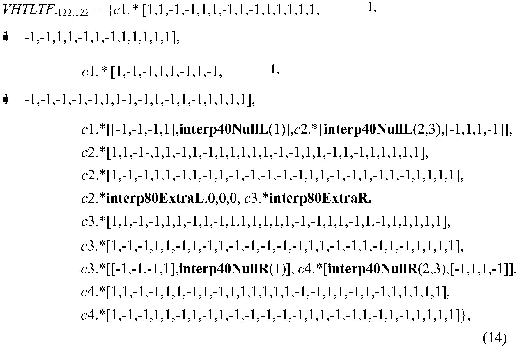
- A preferred VHT-LTF sequence constructed for transmission over 80MHz channel based on the pattern defined by equation (14) may achieve a PAPR of 4.48 dB (4-times oversampling with IFFT of size 1024) by using the phase rotation pattern [c1 c2 c3 c4] =[11-1 1], or alternatively [-1 -1 1 -1], [j j -j j], [-j -j j -j], while the interpolating sequences may be [interp40NullL, interp80ExtraL, interp80ExtraR, interp40NullR] = [1 1 1, -1 -1 -1 1, 1 -1 -1 -1, 1 1 -1]. The entire VHT-LTF pattern (excluding phase rotation per 20MHz sub-channel) is illustrated in
FIG. 8A , where each row of thebit pattern 802 may correspond to one of the four 20MHz sub-channels. The proposed 80MHz VHT-LTF pattern 802 may be 0.24 dB better in PAPR than the optimal pattern from the constraint search space assuming equal null tone values for the upper and lower 40MHz sub-bands. - In another aspect of the present disclosure, optimization of the VHT-LTF sequence may be performed by applying the single stream values 700 on pilot tones. The VHT-LTF sequence may be constructed for 80MHz channel by utilizing all 40MHz 802.11n tones on both 40MHz sub-channels, replacing the tone values at pilot tones with the
single stream pilots 700 fromFIG. 7A , with filling of missing tones and applying a phase rotation on each 20MHz sub-channel. In this case, the constructed VHT-LTF pattern may be defined as:
- A preferred VHT-LTF sequence constructed for transmission over 80MHz channel based on the pattern defined by equation (15) may have a minimal worse case PAPR of 5.0722 dB (4-times oversampling with IFFT of size 1024) over all P and R values by using the phase rotation pattern [c1 c2 c3 c4] = [-1 1 1 1], or alternatively [1 - 1 -1 -1], [-j j j j], [j -j -j -j], while the interpolating sequences may be [interp40NullL, interp80ExtraL, interp80ExtraR, interp40NullR] = [-1 1 1, -1 -1 1 -1, 1 -1 -1 1, 1 -1 1]. The entire VHT-LTF pattern (excluding phase rotation per 20MHz sub-channel) is illustrated in
FIG. 8B , where each row of thebit pattern 804 may correspond to one of the four 20MHz sub-channels. For the preferred VHT-LTF sequence, the product of applied P and R values may be equal to exp(-j2π/3) or exp(-j4π/3). - In yet another aspect of the present disclosure, optimization of the VHT-LTF sequence may be performed by utilizing a new pilot pattern. Pilot values may be the same as the HT-LTF (High Throughput Long Training Field) values at the pilot tones. In this case, the 80MHz subcarrier sequence for VHT-LTF may be constructed by using all 40MHz 802.1 In tones on both 40MHz sub-channels, with filling of missing tones and applying a phase rotation on each 20MHz sub-channel. The constructed VHT-LTF pattern may be defined as:

- A preferred VHT-LTF sequence constructed for transmission over 80MHz channel based on the pattern defined by equation (16) may have a minimal worse case PAPR of 5.2070 dB (4-times oversampling with IFFT of size 1024) over all P and R values by using the phase rotation [c1 c2 c3 c4] = [-1 1 1 1], or alternatively [1 -1 -1 -1] , [-j j j j], [j -j -j -j], while the interpolating sequences may be [interp40NullL, interp80ExtraL, interp80ExtraR, interp40NullR] = [1 -1 1, 1 -1 1 -1, 1 -1 -1 1, 1 -1 1]. The entire VHT-LTF pattern (excluding phase rotation per 20MHz sub-channel) is illustrated in
FIG. 8C , where each row of thebit pattern 806 may correspond to one of the four 20MHz sub-channels. For the preferred VHT-LTF sequence, the product of applied P and R values may be equal to cxp(-j2π/3) or exp(-j4π/3). -
FIG. 9 illustratesexample operations 900 for constructing the VHT-LTF sequence for transmission over 80MHz channel in accordance with certain aspects of the present disclosure. In an aspect, theoperations 900 may be performed at theaccess point 110 of thewireless communications system 100 fromFIG. 1 . At 902, the VHT-LTF sequence may be constructed by combining a plurality of interpolating sequences with LTF tone values associated with at least one of the IEEE 802.11n wireless communications standard or the IEEE 802.11 a wireless communications standard, wherein the LTF tone values may cover at least a portion of bandwidth of a first size, and each of the LTF tone values may be repeated one or more times for different subcarriers. At 904, phases of tones of the VHT-LTF sequence may be rotated per bandwidth of the first size (e.g., with different values of c1, c2, c3 and c4 of rotational patterns [c1 c2 c3 c4] applied per 20MHz sub-band) in an effort to minimize (or at least reduce) PAPR during a transmission of the VHT-LTF sequence. Further, phases of a plurality of tones of the LTF sequence may be rotated in an effort to reduce the PAPR, wherein the plurality of tones may belong to a portion of the bandwidth of a second size. At 906, tones of the VHT-LTF sequence at pilot locations may be replaced with a stream of values (e.g., with thestream 700 fromFIG. 7A ) chosen in an effort to reduce the PAPR. - In an aspect of the present disclosure, tones of the VHT-LTF sequence at non-pilot locations may be multiplied with one or more values (e.g., P-values), while tones of the VHT-LTF sequence at the pilot locations may be multiplied with one or more other values (e.g., R-values), wherein the one or more values and the one or more other values may be determined in an effort to reduce a largest PAPR among all PAPR results associated with the transmission of the VHT-LTF sequence.
- The constructed VHT-LTF sequence may be transmitted over a wireless channel by utilizing the bandwidth of second size. In an aspect of the present disclosure, the bandwidth of first size may comprise at least one of a bandwidth of 20MHz or a bandwidth of 40MHz, and the bandwidth of second size may comprise a bandwidth of 80MHz.
- Referring back to
FIG. 4 , certain aspects of the present disclosure support several options for designing the Legacy Long Training Field (L-LTF) 406 and Legacy Short Training Field (L-STF) 404 of thelegacy part 402 of thepreamble 400 in an effort to reduce PAPR at a transmitting node. The legacy part of preamble may comprise a portion of the preamble recognizable by wireless nodes communicating according to previous, current and future wireless communications standards. - Certain aspects of the present disclosure support several cases how a phase rotation complementary sequence may be designed in an effort to reduce PAPR while transmitting at least on of the L-LTF and L-STF. In the first case, the phase rotation pattern may be given as c = [c(1) c(2) c(3) c(4)], where c(i) = 1, -1, j, -j. This rotation pattern may have potential co-existence detection issue, depending on implementation. In the second case, the phase rotation pattern may be given as c = [a a*j b b*j], where a, b = 1, -1, j, -j. In this case, there may be no co-existence detection issue. In the third case, the phase rotation pattern may be given as c = [1 j e d], where e, d = 1, -1, j, -j, except d = e*j. This rotation pattern may also have potential co-existence detection issue, depending on implementation. In the fourth case, the phase rotation pattern may be given as c = [1 j b b*j], where b may be any complex number. In this case, there may be no co-existence detection issues.
-
FIG. 10A illustrates examples minimal PAPR results for each of the aforementioned four cases of designing the phase rotation pattern for constructing the L-LTF sequence in accordance with certain aspects of the present disclosure. It can be observed fromFIG. 10A that the best PAPR result of 5.3962 dB may be achieved for the phase rotation pattern c = [c(1) c(2) c(3) c(4)] =[-1 1 1 1]. -
FIG. 10B illustrates examples minimal PAPR results for each of the aforementioned four cases of designing the phase rotation pattern for constructing the L-STF sequence in accordance with certain aspects of the present disclosure. It can be observed fromFIG. 10B that the best PAPR result of 4.3480 dB may be achieved for the rotation pattern c = [c(1) c(2) c(3) c(4)] = [-1 1 1 1] or c = [c(1) c(2) c(3) c(4)] = [11 1 -1]. - It can be observed from
FIGS. 10A-10B that, for both L-LTF and L-STF sequences, the same phase rotation pattern of c = [c(1) c(2) c(3) c(4)] = [-1 1 1 1] may provide the best PAPR result. Further, the phase rotation pattern c = [1 j e d] (i.e., the third case) may result in slightly worse PAPR (i.e., less than 0.2, as given inFIG. 10A and FIG. 10B ) by using rotation patterns [1 j -1 j] or [1 j 1 -j]. In addition, same phase rotation patterns applied on tones of at least one of the L-STF or the L-LTF (e.g., the phase rotation pattern of c = [-1 1 1 1]) may be also applicable to modify phases of tones in at least one of the L-SIG field 408 or the VHT-SIG-A fields legacy part 402 of thepreamble 400 illustrated inFIG. 4 for achieving preferred PAPR results. - To summarize, the present disclosure provides a method and apparatus for constructing VHT-LTF sequences for transmission over 80MHz channel in an effort to provide preferred PAPR results at a transmitting node. The VHT-LTF sequences may be constructed utilizing at least one of 40MHz 802.11n LTF values, 20MHz 802.11n LTF values or 20MHz 802.11 a LTF values, with appropriately chosen phase rotation per 20MHz sub-band and with appropriately chosen extra subcarrier values in an effort to minimize (or at least reduce) PAPR.
- The same aforementioned approach for constructing VHT-LTF sequences for 80MHz channel bandwidth may be also used for other numbers of subcarriers. In an aspect of the present disclosure, for supporting IEEE 802.11 ac wireless communication standard, a few tones at band edges may be zeroed out. In another aspect, all tones around DC may be utilized.
- The various operations of methods described above may be performed by any suitable means capable of performing the corresponding functions. The means may include various hardware and/or software component(s) and/or module(s), including, but not limited to a circuit, an application specific integrate circuit (ASIC), or processor. Generally, where there are operations illustrated in Figures, those operations may have corresponding counterpart means-plus-function components with similar numbering. For example,
operations 900 illustrated inFIG. 9 correspond tocomponents 900A illustrated inFIG. 9A . - As used herein, the term "determining" encompasses a wide variety of actions. For example, "determining" may include calculating, computing, processing, deriving, investigating, looking up (e.g., looking up in a table, a database or another data structure), ascertaining and the like. Also, "determining" may include receiving (e.g., receiving information), accessing (e.g., accessing data in a memory) and the like. Also, "determining" may include resolving, selecting, choosing, establishing and the like.
- As used herein, a phrase referring to "at least one of" a list of items refers to any combination of those items, including single members. As an example, "at least one of: a, b, or c" is intended to cover: a, b, c, a-b, a-c, b-c, and a-b-c.
- The various operations of methods described above may be performed by any suitable means capable of performing the operations, such as various hardware and/or software component(s), circuits, and/or module(s). Generally, any operations illustrated in the Figures may be performed by corresponding functional means capable of performing the operations.
- For example, the means for constructing may comprise an application specific integrated circuit, e.g., the
TX data processor 202 of thewireless node 200 fromFIG. 2 or theprocessor 304 of theprocessing system 300 fromFIG. 3 . The means for rotating may comprise an application specific integrated circuit, e.g., theTX data processor 202 of thewireless node 200 or theprocessor 304 of theprocessing system 300. The means for replacing may comprise an application specific integrated circuit, e.g., theTX data processor 202 of thewireless node 200 or theprocessor 304 of theprocessing system 300. The means for transmitting may comprise a transmitter, e.g., thetransceiver 206 of thewireless node 200. The means for designing may comprise an application specific integrated circuit, e.g., theTX data processor 202 of thewireless node 200 or theprocessor 304 of theprocessing system 300. The means for performing oversampling may comprise a sampling circuit, e.g., thetransceiver 206 of thewireless node 200. The means for multiplying may comprise an application specific integrated circuit, e.g., theTX data processor 202 of thewireless node 200 or theprocessor 304 of theprocessing system 300. The means for utilizing may comprise an application specific integrated circuit, e.g., theTX data processor 202 of thewireless node 200 or theprocessor 304 of theprocessing system 300. The means for modifying may comprise an application specific integrated circuit, e.g., theTX data processor 202 of thewireless node 200 or theprocessor 304 of theprocessing system 300. - The various illustrative logical blocks, modules and circuits described in connection with the present disclosure may be implemented or performed with a general purpose processor, a digital signal processor (DSP), an application specific integrated circuit (ASIC), a field programmable gate array signal (FPGA) or other programmable logic device (PLD), discrete gate or transistor logic, discrete hardware components or any combination thereof designed to perform the functions described herein. A general purpose processor may be a microprocessor, but in the alternative, the processor may be any commercially available processor, controller, microcontroller or state machine. A processor may also be implemented as a combination of computing devices, e.g., a combination of a DSP and a microprocessor, a plurality of microprocessors, one or more microprocessors in conjunction with a DSP core, or any other such configuration.
- The steps of a method or algorithm described in connection with the present disclosure may be embodied directly in hardware, in a software module executed by a processor, or in a combination of the two. A software module may reside in any form of storage medium that is known in the art. Some examples of storage media that may be used include random access memory (RAM), read only memory (ROM), flash memory, EPROM memory, EEPROM memory, registers, a hard disk, a removable disk, a CD-ROM and so forth. A software module may comprise a single instruction, or many instructions, and may be distributed over several different code segments, among different programs, and across multiple storage media. A storage medium may be coupled to a processor such that the processor can read information from, and write information to, the storage medium. In the alternative, the storage medium may be integral to the processor.
- The methods disclosed herein comprise one or more steps or actions for achieving the described method. The method steps and/or actions may be interchanged with one another without departing from the scope of the claims. In other words, unless a specific order of steps or actions is specified, the order and/or use of specific steps and/or actions may be modified without departing from the scope of the claims.
- The functions described may be implemented in hardware, software, firmware, or any combination thereof. If implemented in software, the functions may be stored or transmitted over as one or more instructions or code on a computer-readable medium. Computer-readable media include both computer storage media and communication media including any medium that facilitates transfer of a computer program from one place to another. A storage medium may be any available medium that can be accessed by a computer. By way of example, and not limitation, such computer-readable media can comprise RAM, ROM, EEPROM, CD-ROM or other optical disk storage, magnetic disk storage or other magnetic storage devices, or any other medium that can be used to carry or store desired program code in the form of instructions or data structures and that can be accessed by a computer. Also, any connection is properly termed a computer-readable medium. For example, if the software is transmitted from a website, server, or other remote source using a coaxial cable, fiber optic cable, twisted pair, digital subscriber line (DSL), or wireless technologies such as infrared (IR), radio, and microwave, then the coaxial cable, fiber optic cable, twisted pair, DSL, or wireless technologies such as infrared, radio, and microwave are included in the definition of medium. Disk and disc, as used herein, include compact disc (CD), laser disc, optical disc, digital versatile disc (DVD), floppy disk, and Blu-ray® disc where disks usually reproduce data magnetically, while discs reproduce data optically with lasers. Thus, in some aspects computer-readable media may comprise non-transitory computer-readable media (e.g., tangible media). In addition, for other aspects computer-readable media may comprise transitory computer-readable media (e.g., a signal). Combinations of the above should also be included within the scope of computer-readable media.
- Thus, certain aspects may comprise a computer program product for performing the operations presented herein. For example, such a computer program product may comprise a computer readable medium having instructions stored (and/or encoded) thereon, the instructions being executable by one or more processors to perform the operations described herein. For certain aspects, the computer program product may include packaging material.
- Software or instructions may also be transmitted over a transmission medium. For example, if the software is transmitted from a website, server, or other remote source using a coaxial cable, fiber optic cable, twisted pair, digital subscriber line (DSL), or wireless technologies such as infrared, radio, and microwave, then the coaxial cable, fiber optic cable, twisted pair, DSL, or wireless technologies such as infrared, radio, and microwave are included in the definition of transmission medium.
- Further, it should be appreciated that modules and/or other appropriate means for performing the methods and techniques described herein can be downloaded and/or otherwise obtained by a user terminal and/or base station as applicable. For example, such a device can be coupled to a server to facilitate the transfer of means for performing the methods described herein. Alternatively, various methods described herein can be provided via storage means (e.g., RAM, ROM, a physical storage medium such as a compact disc (CD) or floppy disk, etc.), such that a user terminal and/or base station can obtain the various methods upon coupling or providing the storage means to the device. Moreover, any other suitable technique for providing the methods and techniques described herein to a device can be utilized.
- It is to be understood that the claims are not limited to the precise configuration and components illustrated above. Various modifications, changes and variations may be made in the arrangement, operation and details of the methods and apparatus described above without departing from the scope of the claims.
- While the foregoing is directed to aspects of the present disclosure, other and further aspects of the disclosure may be devised without departing from the basic scope thereof, and the scope thereof is determined by the claims that follow.
Claims (15)
- A method for wireless communications, comprising:constructing (902) a long training field LTF sequence of a preamble by combining a plurality of interpolating sequences with LTF tone values associated with at least one of the IEEE 802.11n standard or the IEEE 802.11a standard, wherein
the LTF tone values cover at least a portion of bandwidth of a first size, and
each of the LTF tone values is repeated one or more times for different subcarriers;rotating (904) phases of tones of the LTF sequence per bandwidth of the first size in an effort to reduce a peak-to-average power ratio PAPR during a transmission of the LTF sequence; andreplacing (906) of the LTF sequence at pilot locations with a defined stream of values chosen in an effort to reduce the PAPR. - The method of claim 1, further comprising:transmitting the LTF sequence within the preamble over a wireless channel by utilizing a bandwidth of a second size;
ortransmitting the LTF sequence within the preamble over a wireless channel by utilizing a bandwidth of 80MHz band;
orrotating phases of a plurality of tones of the LTF sequence in an effort to reduce the PAPR, wherein the plurality of tones belongs to a portion of the bandwidth of the second size;
orperforming oversampling before transmitting the LTF sequence;
orutilizing different null tone values at different portions of a bandwidth associated with the transmission of the LTF sequence, wherein each of the portions of bandwidth comprises 40MHz band. - The method of claim 1,
wherein constructing the LTF sequence comprises designing the plurality of interpolating sequences in an effort to reduce the PAPR;
or
wherein the bandwidth of the first size comprises at least one of 20MHz band or 40MHz band;
or
wherein the LTF sequence comprises at most three zero tone values on subcarriers around DC subcarrier. - The method of claim 1, further comprising:multiplying tones of the LTF sequence at non-pilot locations with one or more values; andmultiplying tones of the LTF sequence at the pilot locations with one or more other values,wherein the one or more values and the one or more other values are determined in an effort to reduce a largest PAPR among all PAPR results associated with the transmission of the LTF sequence.
- The method of claim 1, further comprising:modifying phases of tones of at least one of a Legacy Long Training Field L-LTF or a Legacy Short Training Field L-STF within a legacy part of the preamble using one or more phase rotation patterns, wherein
the one or more phase rotation patterns are determined in an effort to reduce a PAPR during transmission of the at least one of L-LTF or L-STF, and
the legacy part of preamble comprises a portion of the preamble recognizable by apparatuses communicating according to previous and current wireless communications standards. - The method of claim 1, further comprising:modifying phases of tones of a legacy part of the preamble using one or more phase rotation patterns, wherein
the legacy part of preamble comprises at least one of a Legacy Short Training Field L-STF, a Legacy Long Training Field L-LTF, a Legacy Signal L-SIG field, or a Very High Throughput Signal field type A VHT-SIGA,
the one or more phase rotation patterns are determined in an effort to reduce a PAPR during transmission of the preamble, and
the legacy part of preamble comprises a portion of the preamble recognizable by apparatuses communicating according to previous and current wireless communications standards. - An apparatus for wireless communications, comprising:means (902A) for constructing a long training field LTF sequence of a preamble by combining a plurality of interpolating sequences with LTF tone values associated with at least one of the IEEE 802.1 In standard or the IEEE 802.11a standard, wherein
the LTF tone values cover at least a portion of bandwidth of a first size, and
each of the LTF tone values is repeated one or more times for different subcarriers;means (904A) for rotating phases of tones of the LTF sequence per bandwidth of the first size in an effort to reduce a peak-to-average power ratio PAPR during a transmission of the LTF sequence; andmeans (906A) replacing tones of the LTF sequence at pilot locations with a defined stream of values chosen in an effort to reduce the PAPR. - The apparatus of claim 7, further comprising:means for transmitting the LTF sequence within the preamble over a wireless channel by utilizing a bandwidth of a second size;
ormeans for transmitting the LTF sequence within the preamble over a wireless channel by utilizing a bandwidth of 80MHz band. - The apparatus of claim 7,
wherein the means for constructing the LTF sequence comprises means for designing the plurality of interpolating sequences in an effort to reduce the PAPR;
or
wherein the bandwidth of the first size comprises at least one of 20MHz band or 40MHz band;
or
wherein the LTF sequence comprises at most three zero tone values on subcarriers around DC subcarrier. - The apparatus of claim 7, further comprising:means for rotating phases of a plurality of tones of the LTF sequence in an effort to reduce the PAPR, wherein the plurality of tones belongs to a portion of the bandwidth of the second size;
ormeans for performing oversampling before transmitting the LTF sequence;
ormeans for utilizing different null tone values at different portions of a bandwidth associated with the transmission of the LTF sequence, wherein each of the portions of bandwidth comprises 40MHz band. - The apparatus of claim 7, further comprising:means for multiplying tones of the LTF sequence at non-pilot locations with one or more values; andmeans for multiplying tones of the LTF sequence at the pilot locations with one or more other values,wherein the one or more values and the one or more other values are determined in an effort to reduce a largest PAPR among all PAPR results associated with the transmission of the LTF sequence.
- The apparatus of claim 7, further comprising:means for modifying phases of tones of at least one of a Legacy Long Training Field L-LTF or a Legacy Short Training Field L-STF within a legacy part of the preamble using one or more phase rotation patterns, whereinthe one or more phase rotation patterns are determined in an effort to reduce a PAPR during transmission of the at least one of L-LTF or L-STF, andthe legacy part of preamble comprises a portion of the preamble recognizable by apparatuses communicating according to previous, current and future wireless communications standards.
- The apparatus of claim 7, further comprising:means for modifying phases of tones of a legacy part of the preamble using one or more phase rotation patterns, whereinthe legacy part of preamble comprises at least one of a Legacy Short Training Field L-STF, a Legacy Long Training Field L-LTF, a Legacy Signal L-SIG field, or a Very High Throughput Signal field type A VHT-SIGA,the one or more phase rotation patterns are determined in an effort to reduce a PAPR during transmission of the preamble, andthe legacy part of preamble comprises a portion of the preamble recognizable by apparatuses communicating according to previous, current and future wireless communications standards.
- A computer-program product for wireless communications, comprising a computer-readable medium comprising instructions executable to:construct a long training field LTF sequence of a preamble by combining a plurality of interpolating sequences with LTF tone values associated with at least one of the IEEE 802.1 In standard or the IEEE 802.11a standard, whereinthe LTF tone values cover at least a portion of bandwidth of a first size, andeach of the LTF tone values is repeated one or more times for different subcarriers;rotate phases of tones of the LTF sequence per bandwidth of the first size in an effort to reduce a peak-to-average power ratio PAPR during a transmission of the LTF sequence; andreplace tones of the LTF sequence at pilot locations with a defined stream of values chosen in an effort to reduce the PAPR.
- An access point, comprising:at least one antenna;a first circuit configured to construct a long training field LTF sequence of a preamble by combining a plurality of interpolating sequences with LTF tone values associated with at least one of the IEEE 802.1 In standard or the IEEE 802.11a standard, whereinthe LTF tone values cover at least a portion of bandwidth of a first size, andeach of the LTF tone values is repeated one or more times for different subcarriers;a second circuit configured to rotate phases of tones of the LTF sequence per bandwidth of the first size in an effort to reduce a peak-to-average power ratio PAPR during a transmission of the LTF sequence;a third circuit configured to replace tones of the LTF sequence at pilot locations with a defined stream of values chosen in an effort to reduce the PAPR; anda transmitter configured to transmit via the at least one antenna the LTF sequence within the preamble over a wireless channel by utilizing a bandwidth of a second size.
Priority Applications (1)
| Application Number | Priority Date | Filing Date | Title |
|---|---|---|---|
| EP16159277.9A EP3048768A1 (en) | 2010-04-06 | 2011-04-06 | Method and apparatus for constructing very high throughput long training field sequences |
Applications Claiming Priority (11)
| Application Number | Priority Date | Filing Date | Title |
|---|---|---|---|
| US32133010P | 2010-04-06 | 2010-04-06 | |
| US32175210P | 2010-04-07 | 2010-04-07 | |
| US32377510P | 2010-04-13 | 2010-04-13 | |
| US33236010P | 2010-05-07 | 2010-05-07 | |
| US33316810P | 2010-05-10 | 2010-05-10 | |
| US33426010P | 2010-05-13 | 2010-05-13 | |
| US34834910P | 2010-05-26 | 2010-05-26 | |
| US35021610P | 2010-06-01 | 2010-06-01 | |
| US35489810P | 2010-06-15 | 2010-06-15 | |
| US13/037,915 US8917784B2 (en) | 2009-07-17 | 2011-03-01 | Method and apparatus for constructing very high throughput long training field sequences |
| PCT/US2011/031449 WO2011127193A1 (en) | 2010-04-06 | 2011-04-06 | Method and apparatus for constructing very high throughput long training field sequences |
Related Child Applications (1)
| Application Number | Title | Priority Date | Filing Date |
|---|---|---|---|
| EP16159277.9A Division EP3048768A1 (en) | 2010-04-06 | 2011-04-06 | Method and apparatus for constructing very high throughput long training field sequences |
Publications (2)
| Publication Number | Publication Date |
|---|---|
| EP2556636A1 EP2556636A1 (en) | 2013-02-13 |
| EP2556636B1 true EP2556636B1 (en) | 2016-03-09 |
Family
ID=44176770
Family Applications (2)
| Application Number | Title | Priority Date | Filing Date |
|---|---|---|---|
| EP16159277.9A Withdrawn EP3048768A1 (en) | 2010-04-06 | 2011-04-06 | Method and apparatus for constructing very high throughput long training field sequences |
| EP11716704.9A Active EP2556636B1 (en) | 2010-04-06 | 2011-04-06 | Method and apparatus for constructing very high throughput long training field sequences |
Family Applications Before (1)
| Application Number | Title | Priority Date | Filing Date |
|---|---|---|---|
| EP16159277.9A Withdrawn EP3048768A1 (en) | 2010-04-06 | 2011-04-06 | Method and apparatus for constructing very high throughput long training field sequences |
Country Status (15)
| Country | Link |
|---|---|
| US (3) | US8917784B2 (en) |
| EP (2) | EP3048768A1 (en) |
| JP (1) | JP5612194B2 (en) |
| KR (2) | KR20140124842A (en) |
| CN (1) | CN102823212B (en) |
| AR (1) | AR081068A1 (en) |
| BR (1) | BR112012025052B1 (en) |
| CA (1) | CA2794289C (en) |
| HK (1) | HK1179433A1 (en) |
| MX (1) | MX2012011585A (en) |
| MY (1) | MY165236A (en) |
| RU (1) | RU2528143C2 (en) |
| TW (1) | TWI450543B (en) |
| WO (1) | WO2011127193A1 (en) |
| ZA (1) | ZA201208312B (en) |
Families Citing this family (62)
| Publication number | Priority date | Publication date | Assignee | Title |
|---|---|---|---|---|
| US8917784B2 (en) | 2009-07-17 | 2014-12-23 | Qualcomm Incorporated | Method and apparatus for constructing very high throughput long training field sequences |
| US8385443B2 (en) | 2009-07-17 | 2013-02-26 | Qualcomm Incorporated | Constructing very high throughput long training field sequences |
| US8553730B2 (en) * | 2009-08-31 | 2013-10-08 | Texas Instruments Incorporated | Short and long training fields |
| KR101783926B1 (en) * | 2009-10-23 | 2017-10-23 | 마벨 월드 트레이드 리미티드 | Number of streams indication for wlan |
| US8532077B2 (en) * | 2010-12-14 | 2013-09-10 | Intel Corporation | Frame format techniques for non-resolvable long training fields in wireless networks |
| US9281924B2 (en) | 2011-04-13 | 2016-03-08 | Qualcomm Incorporated | Method and apparatus for generating various transmission modes for WLAN systems |
| US9350505B2 (en) * | 2011-04-24 | 2016-05-24 | Broadcom Corporation | Peak to average power ratio (PAPR) reduction for repetition mode within single user, multiple user, multiple access, and/or MIMO wireless communications |
| KR102066646B1 (en) * | 2011-10-27 | 2020-01-16 | 마벨 월드 트레이드 리미티드 | Data unit format signalling for wireless local area networks (wlans) |
| WO2013086311A1 (en) * | 2011-12-07 | 2013-06-13 | Drexel University | A joint bit loading and symbol rotation scheme for multi-carrier systems in siso and mimo links |
| KR20130142932A (en) * | 2012-06-19 | 2013-12-30 | 한국전자통신연구원 | Method and apparatus for ofdm transmission in wireless lan |
| KR20160083868A (en) * | 2013-11-07 | 2016-07-12 | 엘지전자 주식회사 | Method and device for receiving multiuser uplink in wireless lan |
| US20150124750A1 (en) * | 2013-11-07 | 2015-05-07 | Qualcomm Incorporated | Single carrier modulation for uplink transmissions |
| US9271241B2 (en) | 2013-11-19 | 2016-02-23 | Intel IP Corporation | Access point and methods for distinguishing HEW physical layer packets with backwards compatibility |
| CN106063146A (en) | 2013-11-19 | 2016-10-26 | 英特尔Ip公司 | HEW station and method for UL MU-MIMO HEW with improved receiver performance |
| CN105659681B (en) | 2013-11-19 | 2019-09-20 | 英特尔Ip公司 | The method, apparatus and computer-readable medium of multi-subscriber dispatching are used in WLAN |
| US9325463B2 (en) | 2013-11-19 | 2016-04-26 | Intel IP Corporation | High-efficiency WLAN (HEW) master station and methods to increase information bits for HEW communication |
| US9544914B2 (en) | 2013-11-19 | 2017-01-10 | Intel IP Corporation | Master station and method for HEW communication using a transmission signaling structure for a HEW signal field |
| EP3072247A4 (en) | 2013-11-19 | 2017-08-23 | Intel IP Corporation | Frame structure with reduced signal field and method for high-efficiency wi-fi (hew) communication |
| WO2015076917A1 (en) | 2013-11-19 | 2015-05-28 | Li Guoqing C | Master station and method for hew communication with signal field configuration for hew ofdma mu-mimo wideband channel operation |
| WO2015120595A1 (en) * | 2014-02-13 | 2015-08-20 | 华为技术有限公司 | Data transmission method and apparatus |
| EP3094057B1 (en) * | 2014-02-14 | 2018-05-30 | Huawei Technologies Co., Ltd. | Method and apparatus for data transmission |
| US9680603B2 (en) | 2014-04-08 | 2017-06-13 | Intel IP Corporation | High-efficiency (HE) communication station and method for communicating longer duration OFDM symbols within 40 MHz and 80 MHz bandwidth |
| WO2015195460A1 (en) * | 2014-06-18 | 2015-12-23 | Intel IP Corporation | High-efficiency (he) communication station and method for communicating longer duration ofdm symbols within 40 mhz and 80 mhz bandwidth allocations |
| EP3161990A4 (en) * | 2014-06-27 | 2018-03-14 | Techflux Ltd. | Bandwidth signaling |
| WO2015198139A1 (en) | 2014-06-27 | 2015-12-30 | Techflux, Ltd. | Method and device for transmitting data unit |
| CN111431688B (en) * | 2014-06-27 | 2023-04-25 | 三星电子株式会社 | Method and device for transmitting data |
| TWI626839B (en) * | 2014-07-15 | 2018-06-11 | 英特爾Ip公司 | High-efficiency (he) communication station and method for communicating longer duration ofdm symbols within 40 mhz and 80 mhz bandwidth allocations |
| EP3496507B1 (en) * | 2014-07-31 | 2022-02-23 | Huawei Technologies Co., Ltd. | Transmission device and method for transmitting data frame |
| KR102305631B1 (en) | 2014-08-21 | 2021-09-28 | 엘지전자 주식회사 | Method for transmitting preamble in wireless lan system |
| EP3186937B1 (en) * | 2014-08-28 | 2023-11-22 | Atlas Global Technologies LLC | Frame transmitting method and frame receiving method |
| US20160105535A1 (en) * | 2014-10-08 | 2016-04-14 | Intel Corporation | Systems and methods for signal classification |
| US9893784B2 (en) * | 2014-10-28 | 2018-02-13 | Newracom, Inc. | LTF design for WLAN system |
| CN105900388B (en) * | 2014-11-04 | 2019-08-27 | 华为技术有限公司 | LTF generation method and device |
| US9660736B2 (en) * | 2014-11-19 | 2017-05-23 | Intel Corporation | Systems, methods, and devices for interference mitigation in wireless networks |
| US10050750B2 (en) * | 2014-12-09 | 2018-08-14 | Qualcomm Incorporated | Training field tone plans for mixed-rate wireless communication networks |
| CN107005525B (en) * | 2015-01-07 | 2020-01-03 | 华为技术有限公司 | Pilot frequency transmission method and data transmission device in wireless local area network |
| US9628310B2 (en) | 2015-03-25 | 2017-04-18 | Newracom, Inc. | Long training field sequence construction |
| US10097393B1 (en) * | 2015-05-27 | 2018-10-09 | Marvell International Ltd. | Systems and methods to reduce peak to average power ratio for dual sub-carrier modulated transmissions in a wireless network |
| US10033565B2 (en) * | 2015-07-27 | 2018-07-24 | Intel Corporation | Low peak-to-average power ratio long training field sequences |
| US9998951B2 (en) | 2015-08-05 | 2018-06-12 | Qualcomm Incorporated | Training sequence generation for wireless communication networks |
| WO2017023135A1 (en) | 2015-08-06 | 2017-02-09 | 엘지전자 주식회사 | Method and apparatus for generating stf signal using binary sequence in wireless lan system |
| CN108551434B (en) * | 2015-08-26 | 2019-04-12 | 华为技术有限公司 | The method and apparatus for transmitting HE-LTF sequence |
| US10567555B2 (en) * | 2015-11-06 | 2020-02-18 | Qualcomm Incorporated | Methods and apparatus for early detection of high efficiency wireless packets in wireless communication |
| CN109462560B (en) | 2015-11-23 | 2020-07-07 | 华为技术有限公司 | Wireless local area network data transmission method and device |
| CN114500210A (en) * | 2016-01-07 | 2022-05-13 | 华为技术有限公司 | Wireless local area network information transmission method and device |
| WO2017155330A1 (en) * | 2016-03-10 | 2017-09-14 | 엘지전자 주식회사 | Method for transmitting signal in wireless lan system, and device therefor |
| CN107786483B (en) * | 2016-08-26 | 2021-08-20 | 华为技术有限公司 | Data signal processing method and related equipment |
| KR102410635B1 (en) * | 2017-05-29 | 2022-06-17 | 영남대학교 산학협력단 | Service teminal and method for signal transmission |
| KR102327032B1 (en) | 2017-12-29 | 2021-11-16 | 한국전자통신연구원 | Method of in-band full-duplex transmission and reception, and apparatus for the same |
| US10952072B2 (en) * | 2018-05-29 | 2021-03-16 | Intel Corporation | Long training field sequence security protection |
| US11683212B2 (en) | 2018-08-27 | 2023-06-20 | Lg Electronics Inc. | Method and apparatus for applying phase rotation in broadband with 80MHz based preamble puncturing performed in WLAN system |
| EP3826257A4 (en) * | 2018-09-07 | 2021-09-22 | LG Electronics Inc. | Method and device for applying optimized phase rotation in wlan environment including wireless devices having mutually different maximum transmittable rf bandwidths |
| WO2020050529A1 (en) * | 2018-09-07 | 2020-03-12 | 엘지전자 주식회사 | Method and apparatus for applying optimized phase rotation in consideration of various rf capabilities in broadband with 80mhz based preamble puncturing in wlan system |
| CN111200568B (en) * | 2018-11-16 | 2021-05-18 | 华为技术有限公司 | Transmitting end device and signal processing method |
| US20220278883A1 (en) * | 2019-08-20 | 2022-09-01 | Lg Electronics Inc. | Method and apparatus for receiving ppdu via broadband in wireless lan system |
| US11677605B2 (en) | 2020-02-24 | 2023-06-13 | Qualcomm Incorporated | Machine learning based uplink coverage enhancement using peak reduction tones |
| WO2021206361A1 (en) * | 2020-04-08 | 2021-10-14 | 엘지전자 주식회사 | Method and device for applying optimized phase rotation to broadband in wireless lan system |
| US20210399933A1 (en) * | 2020-06-22 | 2021-12-23 | Qualcomm Incorporated | Long training field with reduced peak-to-average power ratio |
| US11849452B2 (en) * | 2020-06-24 | 2023-12-19 | Lg Electronics Inc. | Configuration of signal field comprising information related to transmission mode |
| US11750431B2 (en) * | 2020-08-31 | 2023-09-05 | Qualcomm Incorporated | Peak reduction tones for full duplex communication |
| US11606240B1 (en) | 2021-09-30 | 2023-03-14 | Silicon Laboratories Inc. | Using preamble portion having irregular carrier spacing for frequency synchronization |
| US20230412325A1 (en) * | 2022-06-17 | 2023-12-21 | Qualcomm Incorporated | Single-carrier frequency-division multiplexing (sc-fdm) for wireless local area networks (wlans) |
Family Cites Families (28)
| Publication number | Priority date | Publication date | Assignee | Title |
|---|---|---|---|---|
| US7599332B2 (en) * | 2004-04-05 | 2009-10-06 | Qualcomm Incorporated | Modified preamble structure for IEEE 802.11a extensions to allow for coexistence and interoperability between 802.11a devices and higher data rate, MIMO or otherwise extended devices |
| KR100933115B1 (en) | 2003-09-09 | 2009-12-21 | 삼성전자주식회사 | Apparatus and method for reducing peak to average power ratio in a orthogonal frequency division multiplexing communication system |
| US7349436B2 (en) | 2003-09-30 | 2008-03-25 | Intel Corporation | Systems and methods for high-throughput wideband wireless local area network communications |
| US7395495B2 (en) | 2004-01-12 | 2008-07-01 | Intel Corporation | Method and apparatus for decoding forward error correction codes |
| US7324605B2 (en) * | 2004-01-12 | 2008-01-29 | Intel Corporation | High-throughput multicarrier communication systems and methods for exchanging channel state information |
| JP2007537655A (en) * | 2004-05-13 | 2007-12-20 | コーニンクレッカ フィリップス エレクトロニクス エヌ ヴィ | Multiple receiver aggregation with different data rates for IEEE 802.11N |
| TWI255105B (en) | 2004-05-20 | 2006-05-11 | Ind Tech Res Inst | Method and apparatus for papr reduction of an ofdm signal |
| KR100739511B1 (en) | 2004-06-25 | 2007-07-13 | 삼성전자주식회사 | Apparatus and method for transmitting/receiving pilot signal in a communication system using orthogonal frequency division multiplexing scheme |
| TWI246273B (en) | 2004-06-28 | 2005-12-21 | Ind Tech Res Inst | Method and apparatus for high-order PAPR reduction of an OFDM signal |
| US8737189B2 (en) * | 2005-02-16 | 2014-05-27 | Broadcom Corporation | Method and system for compromise greenfield preambles for 802.11n |
| JP4680264B2 (en) | 2004-12-02 | 2011-05-11 | ニュー ジャージー インスティチュート オブ テクノロジー | Method and / or system for PAPR reduction |
| WO2006102745A1 (en) | 2005-03-30 | 2006-10-05 | Nortel Networks Limited | Method and system for combining ofdm and transformed ofdm |
| JP2008507233A (en) | 2005-06-09 | 2008-03-06 | サムスン エレクトロニクス カンパニー リミテッド | Method and apparatus for transmitting / receiving legacy data over high-speed wireless network |
| KR100643299B1 (en) | 2005-06-09 | 2006-11-10 | 삼성전자주식회사 | Method and apparatus for transmitting and receiving legacy format data in high throughput wireless network |
| US7773681B2 (en) | 2005-08-05 | 2010-08-10 | Interdigital Technology Corporation | Method and apparatus for estimating signal-to-noise ratio, noise power, and signal power |
| US7855993B2 (en) | 2005-08-23 | 2010-12-21 | Agere Systems Inc. | Method and apparatus for reducing power fluctuations during preamble training in a multiple antenna communication system using cyclic delays |
| KR101165629B1 (en) | 2005-11-03 | 2012-07-17 | 엘지전자 주식회사 | Method and apparatus for producing/recovering OFDM signals |
| KR101306696B1 (en) | 2005-11-10 | 2013-09-10 | 엘지전자 주식회사 | apparatus and method for transmitting data using a plurality of carriers |
| JP4924106B2 (en) | 2006-04-27 | 2012-04-25 | ソニー株式会社 | Wireless communication system, wireless communication apparatus, and wireless communication method |
| US7860128B2 (en) | 2006-06-28 | 2010-12-28 | Samsung Electronics Co., Ltd. | System and method for wireless communication of uncompressed video having a preamble design |
| TWI451728B (en) | 2006-09-29 | 2014-09-01 | Koninkl Philips Electronics Nv | Cost-effective preamble structure for high-speed communication of packetized systems |
| WO2009022856A2 (en) | 2007-08-14 | 2009-02-19 | Lg Electronics Inc. | Peak to average power ratio reduction |
| TW200926655A (en) | 2007-12-10 | 2009-06-16 | Univ Nat Taiwan | Method of using unitary transformation to solve high peak-to-average power ratio problem for multi-carrier modulation communication system |
| US8483235B2 (en) | 2007-12-11 | 2013-07-09 | Electronics And Telecommunications Research Institute | Apparatus and method for channel estimation in MIMO systems |
| US8155138B2 (en) | 2008-08-19 | 2012-04-10 | Qualcomm Incorporated | Training sequences for very high throughput wireless communication |
| US8165232B2 (en) | 2008-10-01 | 2012-04-24 | Harris Corporation | Low peak-to-average power ratio (PAPR) preamble for orthogonal frequency division multiplexing (OFDM) communications |
| US8917784B2 (en) | 2009-07-17 | 2014-12-23 | Qualcomm Incorporated | Method and apparatus for constructing very high throughput long training field sequences |
| US8385443B2 (en) | 2009-07-17 | 2013-02-26 | Qualcomm Incorporated | Constructing very high throughput long training field sequences |
-
2011
- 2011-03-01 US US13/037,915 patent/US8917784B2/en active Active
- 2011-04-06 KR KR1020147025420A patent/KR20140124842A/en not_active Application Discontinuation
- 2011-04-06 EP EP16159277.9A patent/EP3048768A1/en not_active Withdrawn
- 2011-04-06 MX MX2012011585A patent/MX2012011585A/en active IP Right Grant
- 2011-04-06 EP EP11716704.9A patent/EP2556636B1/en active Active
- 2011-04-06 BR BR112012025052-3A patent/BR112012025052B1/en active IP Right Grant
- 2011-04-06 MY MYPI2012004214A patent/MY165236A/en unknown
- 2011-04-06 CA CA2794289A patent/CA2794289C/en active Active
- 2011-04-06 TW TW100111869A patent/TWI450543B/en active
- 2011-04-06 WO PCT/US2011/031449 patent/WO2011127193A1/en active Application Filing
- 2011-04-06 KR KR1020127029141A patent/KR101623434B1/en active IP Right Grant
- 2011-04-06 CN CN201180016792.6A patent/CN102823212B/en active Active
- 2011-04-06 RU RU2012146971/08A patent/RU2528143C2/en active
- 2011-04-06 JP JP2013503922A patent/JP5612194B2/en active Active
- 2011-04-06 AR ARP110101156A patent/AR081068A1/en active IP Right Grant
-
2012
- 2012-11-05 ZA ZA2012/08312A patent/ZA201208312B/en unknown
-
2013
- 2013-05-28 HK HK13106317.8A patent/HK1179433A1/en unknown
-
2014
- 2014-11-11 US US14/538,629 patent/US9756526B2/en active Active
-
2017
- 2017-04-06 US US15/480,643 patent/US10153933B2/en active Active
Also Published As
| Publication number | Publication date |
|---|---|
| TW201203962A (en) | 2012-01-16 |
| EP3048768A1 (en) | 2016-07-27 |
| ZA201208312B (en) | 2013-07-31 |
| BR112012025052A2 (en) | 2016-06-21 |
| RU2012146971A (en) | 2014-05-20 |
| US9756526B2 (en) | 2017-09-05 |
| TWI450543B (en) | 2014-08-21 |
| MY165236A (en) | 2018-03-14 |
| KR20140124842A (en) | 2014-10-27 |
| WO2011127193A1 (en) | 2011-10-13 |
| KR20130008060A (en) | 2013-01-21 |
| CA2794289C (en) | 2016-06-14 |
| US20110194544A1 (en) | 2011-08-11 |
| US8917784B2 (en) | 2014-12-23 |
| CN102823212B (en) | 2015-08-12 |
| US20170230214A1 (en) | 2017-08-10 |
| US20150063288A1 (en) | 2015-03-05 |
| BR112012025052B1 (en) | 2021-09-14 |
| EP2556636A1 (en) | 2013-02-13 |
| JP5612194B2 (en) | 2014-10-22 |
| CN102823212A (en) | 2012-12-12 |
| MX2012011585A (en) | 2012-11-29 |
| HK1179433A1 (en) | 2013-09-27 |
| AR081068A1 (en) | 2012-06-06 |
| JP2013526139A (en) | 2013-06-20 |
| RU2528143C2 (en) | 2014-09-10 |
| KR101623434B1 (en) | 2016-05-23 |
| US10153933B2 (en) | 2018-12-11 |
| CA2794289A1 (en) | 2011-10-13 |
Similar Documents
| Publication | Publication Date | Title |
|---|---|---|
| EP2556636B1 (en) | Method and apparatus for constructing very high throughput long training field sequences | |
| CA2768139C (en) | Constructing very high throughput long training field sequences | |
| US8717865B2 (en) | Method and apparatus for constructing very high throughput short training field sequences | |
| US9439161B2 (en) | Physical layer design for uplink (UL) multiuser multiple-input, multiple-output (MU-MIMO) in wireless local area network (WLAN) systems | |
| US8867574B2 (en) | Format of VHT-SIG-B and service fields in IEEE 802.11AC | |
| US8743784B2 (en) | VHT-SIG-B field in null data packets (NDPs) | |
| US20110013583A1 (en) | Constructing very high throughput short training field sequences | |
| EP2985965A1 (en) | Constructing very high throughput signal (vht-sig) fields for reduced peak-to-average power ratio (papr) | |
| CN111837370A (en) | Simplified detection of spatial modulation and space-time block coding with antenna selection |
Legal Events
| Date | Code | Title | Description |
|---|---|---|---|
| PUAI | Public reference made under article 153(3) epc to a published international application that has entered the european phase |
Free format text: ORIGINAL CODE: 0009012 |
|
| 17P | Request for examination filed |
Effective date: 20121106 |
|
| AK | Designated contracting states |
Kind code of ref document: A1 Designated state(s): AL AT BE BG CH CY CZ DE DK EE ES FI FR GB GR HR HU IE IS IT LI LT LU LV MC MK MT NL NO PL PT RO RS SE SI SK SM TR |
|
| DAX | Request for extension of the european patent (deleted) | ||
| GRAP | Despatch of communication of intention to grant a patent |
Free format text: ORIGINAL CODE: EPIDOSNIGR1 |
|
| INTG | Intention to grant announced |
Effective date: 20150407 |
|
| GRAP | Despatch of communication of intention to grant a patent |
Free format text: ORIGINAL CODE: EPIDOSNIGR1 |
|
| INTG | Intention to grant announced |
Effective date: 20150827 |
|
| GRAS | Grant fee paid |
Free format text: ORIGINAL CODE: EPIDOSNIGR3 |
|
| GRAA | (expected) grant |
Free format text: ORIGINAL CODE: 0009210 |
|
| AK | Designated contracting states |
Kind code of ref document: B1 Designated state(s): AL AT BE BG CH CY CZ DE DK EE ES FI FR GB GR HR HU IE IS IT LI LT LU LV MC MK MT NL NO PL PT RO RS SE SI SK SM TR |
|
| REG | Reference to a national code |
Ref country code: GB Ref legal event code: FG4D |
|
| REG | Reference to a national code |
Ref country code: AT Ref legal event code: REF Ref document number: 780212 Country of ref document: AT Kind code of ref document: T Effective date: 20160315 Ref country code: CH Ref legal event code: EP |
|
| REG | Reference to a national code |
Ref country code: IE Ref legal event code: FG4D |
|
| REG | Reference to a national code |
Ref country code: DE Ref legal event code: R096 Ref document number: 602011023832 Country of ref document: DE |
|
| REG | Reference to a national code |
Ref country code: LT Ref legal event code: MG4D |
|
| REG | Reference to a national code |
Ref country code: NL Ref legal event code: MP Effective date: 20160309 |
|
| PG25 | Lapsed in a contracting state [announced via postgrant information from national office to epo] |
Ref country code: NO Free format text: LAPSE BECAUSE OF FAILURE TO SUBMIT A TRANSLATION OF THE DESCRIPTION OR TO PAY THE FEE WITHIN THE PRESCRIBED TIME-LIMIT Effective date: 20160609 Ref country code: ES Free format text: LAPSE BECAUSE OF FAILURE TO SUBMIT A TRANSLATION OF THE DESCRIPTION OR TO PAY THE FEE WITHIN THE PRESCRIBED TIME-LIMIT Effective date: 20160309 Ref country code: HR Free format text: LAPSE BECAUSE OF FAILURE TO SUBMIT A TRANSLATION OF THE DESCRIPTION OR TO PAY THE FEE WITHIN THE PRESCRIBED TIME-LIMIT Effective date: 20160309 Ref country code: GR Free format text: LAPSE BECAUSE OF FAILURE TO SUBMIT A TRANSLATION OF THE DESCRIPTION OR TO PAY THE FEE WITHIN THE PRESCRIBED TIME-LIMIT Effective date: 20160610 Ref country code: FI Free format text: LAPSE BECAUSE OF FAILURE TO SUBMIT A TRANSLATION OF THE DESCRIPTION OR TO PAY THE FEE WITHIN THE PRESCRIBED TIME-LIMIT Effective date: 20160309 |
|
| REG | Reference to a national code |
Ref country code: AT Ref legal event code: MK05 Ref document number: 780212 Country of ref document: AT Kind code of ref document: T Effective date: 20160309 |
|
| PG25 | Lapsed in a contracting state [announced via postgrant information from national office to epo] |
Ref country code: LV Free format text: LAPSE BECAUSE OF FAILURE TO SUBMIT A TRANSLATION OF THE DESCRIPTION OR TO PAY THE FEE WITHIN THE PRESCRIBED TIME-LIMIT Effective date: 20160309 Ref country code: LT Free format text: LAPSE BECAUSE OF FAILURE TO SUBMIT A TRANSLATION OF THE DESCRIPTION OR TO PAY THE FEE WITHIN THE PRESCRIBED TIME-LIMIT Effective date: 20160309 Ref country code: RS Free format text: LAPSE BECAUSE OF FAILURE TO SUBMIT A TRANSLATION OF THE DESCRIPTION OR TO PAY THE FEE WITHIN THE PRESCRIBED TIME-LIMIT Effective date: 20160309 Ref country code: BE Free format text: LAPSE BECAUSE OF NON-PAYMENT OF DUE FEES Effective date: 20160430 Ref country code: SE Free format text: LAPSE BECAUSE OF FAILURE TO SUBMIT A TRANSLATION OF THE DESCRIPTION OR TO PAY THE FEE WITHIN THE PRESCRIBED TIME-LIMIT Effective date: 20160309 Ref country code: NL Free format text: LAPSE BECAUSE OF FAILURE TO SUBMIT A TRANSLATION OF THE DESCRIPTION OR TO PAY THE FEE WITHIN THE PRESCRIBED TIME-LIMIT Effective date: 20160309 Ref country code: PL Free format text: LAPSE BECAUSE OF FAILURE TO SUBMIT A TRANSLATION OF THE DESCRIPTION OR TO PAY THE FEE WITHIN THE PRESCRIBED TIME-LIMIT Effective date: 20160309 |
|
| PG25 | Lapsed in a contracting state [announced via postgrant information from national office to epo] |
Ref country code: IS Free format text: LAPSE BECAUSE OF FAILURE TO SUBMIT A TRANSLATION OF THE DESCRIPTION OR TO PAY THE FEE WITHIN THE PRESCRIBED TIME-LIMIT Effective date: 20160709 Ref country code: EE Free format text: LAPSE BECAUSE OF FAILURE TO SUBMIT A TRANSLATION OF THE DESCRIPTION OR TO PAY THE FEE WITHIN THE PRESCRIBED TIME-LIMIT Effective date: 20160309 |
|
| PG25 | Lapsed in a contracting state [announced via postgrant information from national office to epo] |
Ref country code: SK Free format text: LAPSE BECAUSE OF FAILURE TO SUBMIT A TRANSLATION OF THE DESCRIPTION OR TO PAY THE FEE WITHIN THE PRESCRIBED TIME-LIMIT Effective date: 20160309 Ref country code: RO Free format text: LAPSE BECAUSE OF FAILURE TO SUBMIT A TRANSLATION OF THE DESCRIPTION OR TO PAY THE FEE WITHIN THE PRESCRIBED TIME-LIMIT Effective date: 20160309 Ref country code: PT Free format text: LAPSE BECAUSE OF FAILURE TO SUBMIT A TRANSLATION OF THE DESCRIPTION OR TO PAY THE FEE WITHIN THE PRESCRIBED TIME-LIMIT Effective date: 20160711 Ref country code: SM Free format text: LAPSE BECAUSE OF FAILURE TO SUBMIT A TRANSLATION OF THE DESCRIPTION OR TO PAY THE FEE WITHIN THE PRESCRIBED TIME-LIMIT Effective date: 20160309 Ref country code: CZ Free format text: LAPSE BECAUSE OF FAILURE TO SUBMIT A TRANSLATION OF THE DESCRIPTION OR TO PAY THE FEE WITHIN THE PRESCRIBED TIME-LIMIT Effective date: 20160309 Ref country code: AT Free format text: LAPSE BECAUSE OF FAILURE TO SUBMIT A TRANSLATION OF THE DESCRIPTION OR TO PAY THE FEE WITHIN THE PRESCRIBED TIME-LIMIT Effective date: 20160309 |
|
| REG | Reference to a national code |
Ref country code: CH Ref legal event code: PL |
|
| REG | Reference to a national code |
Ref country code: DE Ref legal event code: R097 Ref document number: 602011023832 Country of ref document: DE |
|
| PG25 | Lapsed in a contracting state [announced via postgrant information from national office to epo] |
Ref country code: IT Free format text: LAPSE BECAUSE OF FAILURE TO SUBMIT A TRANSLATION OF THE DESCRIPTION OR TO PAY THE FEE WITHIN THE PRESCRIBED TIME-LIMIT Effective date: 20160309 Ref country code: BE Free format text: LAPSE BECAUSE OF FAILURE TO SUBMIT A TRANSLATION OF THE DESCRIPTION OR TO PAY THE FEE WITHIN THE PRESCRIBED TIME-LIMIT Effective date: 20160309 |
|
| PLBE | No opposition filed within time limit |
Free format text: ORIGINAL CODE: 0009261 |
|
| STAA | Information on the status of an ep patent application or granted ep patent |
Free format text: STATUS: NO OPPOSITION FILED WITHIN TIME LIMIT |
|
| REG | Reference to a national code |
Ref country code: IE Ref legal event code: MM4A |
|
| REG | Reference to a national code |
Ref country code: FR Ref legal event code: ST Effective date: 20161230 |
|
| PG25 | Lapsed in a contracting state [announced via postgrant information from national office to epo] |
Ref country code: LI Free format text: LAPSE BECAUSE OF NON-PAYMENT OF DUE FEES Effective date: 20160430 Ref country code: DK Free format text: LAPSE BECAUSE OF FAILURE TO SUBMIT A TRANSLATION OF THE DESCRIPTION OR TO PAY THE FEE WITHIN THE PRESCRIBED TIME-LIMIT Effective date: 20160309 Ref country code: CH Free format text: LAPSE BECAUSE OF NON-PAYMENT OF DUE FEES Effective date: 20160430 Ref country code: FR Free format text: LAPSE BECAUSE OF NON-PAYMENT OF DUE FEES Effective date: 20160509 |
|
| 26N | No opposition filed |
Effective date: 20161212 |
|
| PG25 | Lapsed in a contracting state [announced via postgrant information from national office to epo] |
Ref country code: BG Free format text: LAPSE BECAUSE OF FAILURE TO SUBMIT A TRANSLATION OF THE DESCRIPTION OR TO PAY THE FEE WITHIN THE PRESCRIBED TIME-LIMIT Effective date: 20160609 |
|
| PG25 | Lapsed in a contracting state [announced via postgrant information from national office to epo] |
Ref country code: SI Free format text: LAPSE BECAUSE OF FAILURE TO SUBMIT A TRANSLATION OF THE DESCRIPTION OR TO PAY THE FEE WITHIN THE PRESCRIBED TIME-LIMIT Effective date: 20160309 Ref country code: IE Free format text: LAPSE BECAUSE OF NON-PAYMENT OF DUE FEES Effective date: 20160406 |
|
| PG25 | Lapsed in a contracting state [announced via postgrant information from national office to epo] |
Ref country code: CY Free format text: LAPSE BECAUSE OF FAILURE TO SUBMIT A TRANSLATION OF THE DESCRIPTION OR TO PAY THE FEE WITHIN THE PRESCRIBED TIME-LIMIT Effective date: 20160309 Ref country code: HU Free format text: LAPSE BECAUSE OF FAILURE TO SUBMIT A TRANSLATION OF THE DESCRIPTION OR TO PAY THE FEE WITHIN THE PRESCRIBED TIME-LIMIT; INVALID AB INITIO Effective date: 20110406 |
|
| PG25 | Lapsed in a contracting state [announced via postgrant information from national office to epo] |
Ref country code: MC Free format text: LAPSE BECAUSE OF FAILURE TO SUBMIT A TRANSLATION OF THE DESCRIPTION OR TO PAY THE FEE WITHIN THE PRESCRIBED TIME-LIMIT Effective date: 20160309 Ref country code: TR Free format text: LAPSE BECAUSE OF FAILURE TO SUBMIT A TRANSLATION OF THE DESCRIPTION OR TO PAY THE FEE WITHIN THE PRESCRIBED TIME-LIMIT Effective date: 20160309 Ref country code: MK Free format text: LAPSE BECAUSE OF FAILURE TO SUBMIT A TRANSLATION OF THE DESCRIPTION OR TO PAY THE FEE WITHIN THE PRESCRIBED TIME-LIMIT Effective date: 20160309 Ref country code: MT Free format text: LAPSE BECAUSE OF NON-PAYMENT OF DUE FEES Effective date: 20160430 Ref country code: LU Free format text: LAPSE BECAUSE OF NON-PAYMENT OF DUE FEES Effective date: 20160406 |
|
| PG25 | Lapsed in a contracting state [announced via postgrant information from national office to epo] |
Ref country code: AL Free format text: LAPSE BECAUSE OF FAILURE TO SUBMIT A TRANSLATION OF THE DESCRIPTION OR TO PAY THE FEE WITHIN THE PRESCRIBED TIME-LIMIT Effective date: 20160309 |
|
| REG | Reference to a national code |
Ref country code: DE Ref legal event code: R082 Ref document number: 602011023832 Country of ref document: DE Representative=s name: MAUCHER JENKINS PATENTANWAELTE & RECHTSANWAELT, DE |
|
| PGFP | Annual fee paid to national office [announced via postgrant information from national office to epo] |
Ref country code: DE Payment date: 20230320 Year of fee payment: 13 |
|
| PGFP | Annual fee paid to national office [announced via postgrant information from national office to epo] |
Ref country code: GB Payment date: 20240314 Year of fee payment: 14 |