EP2556295B1 - Conformal oled luminaire with color control - Google Patents
Conformal oled luminaire with color control Download PDFInfo
- Publication number
- EP2556295B1 EP2556295B1 EP11710083.4A EP11710083A EP2556295B1 EP 2556295 B1 EP2556295 B1 EP 2556295B1 EP 11710083 A EP11710083 A EP 11710083A EP 2556295 B1 EP2556295 B1 EP 2556295B1
- Authority
- EP
- European Patent Office
- Prior art keywords
- panel
- luminaire
- panel portions
- light emitting
- oled
- Prior art date
- Legal status (The legal status is an assumption and is not a legal conclusion. Google has not performed a legal analysis and makes no representation as to the accuracy of the status listed.)
- Active
Links
Images






Classifications
-
- F—MECHANICAL ENGINEERING; LIGHTING; HEATING; WEAPONS; BLASTING
- F21—LIGHTING
- F21V—FUNCTIONAL FEATURES OR DETAILS OF LIGHTING DEVICES OR SYSTEMS THEREOF; STRUCTURAL COMBINATIONS OF LIGHTING DEVICES WITH OTHER ARTICLES, NOT OTHERWISE PROVIDED FOR
- F21V14/00—Controlling the distribution of the light emitted by adjustment of elements
- F21V14/02—Controlling the distribution of the light emitted by adjustment of elements by movement of light sources
-
- F—MECHANICAL ENGINEERING; LIGHTING; HEATING; WEAPONS; BLASTING
- F21—LIGHTING
- F21S—NON-PORTABLE LIGHTING DEVICES; SYSTEMS THEREOF; VEHICLE LIGHTING DEVICES SPECIALLY ADAPTED FOR VEHICLE EXTERIORS
- F21S6/00—Lighting devices intended to be free-standing
- F21S6/005—Lighting devices intended to be free-standing with a lamp housing maintained at a distance from the floor or ground via a support, e.g. standing lamp for ambient lighting
-
- F—MECHANICAL ENGINEERING; LIGHTING; HEATING; WEAPONS; BLASTING
- F21—LIGHTING
- F21S—NON-PORTABLE LIGHTING DEVICES; SYSTEMS THEREOF; VEHICLE LIGHTING DEVICES SPECIALLY ADAPTED FOR VEHICLE EXTERIORS
- F21S8/00—Lighting devices intended for fixed installation
- F21S8/04—Lighting devices intended for fixed installation intended only for mounting on a ceiling or the like overhead structures
- F21S8/06—Lighting devices intended for fixed installation intended only for mounting on a ceiling or the like overhead structures by suspension
-
- F—MECHANICAL ENGINEERING; LIGHTING; HEATING; WEAPONS; BLASTING
- F21—LIGHTING
- F21S—NON-PORTABLE LIGHTING DEVICES; SYSTEMS THEREOF; VEHICLE LIGHTING DEVICES SPECIALLY ADAPTED FOR VEHICLE EXTERIORS
- F21S10/00—Lighting devices or systems producing a varying lighting effect
- F21S10/02—Lighting devices or systems producing a varying lighting effect changing colors
-
- F—MECHANICAL ENGINEERING; LIGHTING; HEATING; WEAPONS; BLASTING
- F21—LIGHTING
- F21S—NON-PORTABLE LIGHTING DEVICES; SYSTEMS THEREOF; VEHICLE LIGHTING DEVICES SPECIALLY ADAPTED FOR VEHICLE EXTERIORS
- F21S9/00—Lighting devices with a built-in power supply; Systems employing lighting devices with a built-in power supply
- F21S9/02—Lighting devices with a built-in power supply; Systems employing lighting devices with a built-in power supply the power supply being a battery or accumulator
-
- F—MECHANICAL ENGINEERING; LIGHTING; HEATING; WEAPONS; BLASTING
- F21—LIGHTING
- F21V—FUNCTIONAL FEATURES OR DETAILS OF LIGHTING DEVICES OR SYSTEMS THEREOF; STRUCTURAL COMBINATIONS OF LIGHTING DEVICES WITH OTHER ARTICLES, NOT OTHERWISE PROVIDED FOR
- F21V33/00—Structural combinations of lighting devices with other articles, not otherwise provided for
- F21V33/0004—Personal or domestic articles
-
- F—MECHANICAL ENGINEERING; LIGHTING; HEATING; WEAPONS; BLASTING
- F21—LIGHTING
- F21Y—INDEXING SCHEME ASSOCIATED WITH SUBCLASSES F21K, F21L, F21S and F21V, RELATING TO THE FORM OR THE KIND OF THE LIGHT SOURCES OR OF THE COLOUR OF THE LIGHT EMITTED
- F21Y2105/00—Planar light sources
-
- F—MECHANICAL ENGINEERING; LIGHTING; HEATING; WEAPONS; BLASTING
- F21—LIGHTING
- F21Y—INDEXING SCHEME ASSOCIATED WITH SUBCLASSES F21K, F21L, F21S and F21V, RELATING TO THE FORM OR THE KIND OF THE LIGHT SOURCES OR OF THE COLOUR OF THE LIGHT EMITTED
- F21Y2105/00—Planar light sources
- F21Y2105/10—Planar light sources comprising a two-dimensional [2D] array of point-like light-generating elements
-
- F—MECHANICAL ENGINEERING; LIGHTING; HEATING; WEAPONS; BLASTING
- F21—LIGHTING
- F21Y—INDEXING SCHEME ASSOCIATED WITH SUBCLASSES F21K, F21L, F21S and F21V, RELATING TO THE FORM OR THE KIND OF THE LIGHT SOURCES OR OF THE COLOUR OF THE LIGHT EMITTED
- F21Y2115/00—Light-generating elements of semiconductor light sources
- F21Y2115/10—Light-emitting diodes [LED]
-
- F—MECHANICAL ENGINEERING; LIGHTING; HEATING; WEAPONS; BLASTING
- F21—LIGHTING
- F21Y—INDEXING SCHEME ASSOCIATED WITH SUBCLASSES F21K, F21L, F21S and F21V, RELATING TO THE FORM OR THE KIND OF THE LIGHT SOURCES OR OF THE COLOUR OF THE LIGHT EMITTED
- F21Y2115/00—Light-generating elements of semiconductor light sources
- F21Y2115/10—Light-emitting diodes [LED]
- F21Y2115/15—Organic light-emitting diodes [OLED]
Definitions
- This disclosure is directed to a luminaire, and more particularly to a luminaire that uses a flexible surface light source such as solid state light source, particularly an organic light emitting device (OLED).
- a solid state light source such as a light emitting device (LED) or an OLED offers a wide range of different applications.
- LED light emitting device
- OLED organic light emitting device
- US 6 270 230 B1 discloses an umbrella with alert device including a circular umbrella cover made of waterproof material, an umbrella frame for supporting the umbrella cover to form an umbrella body, and an alert device for providing visual warning signal to others.
- WO 2010/004073 A1 discloses a tent with integrated lighting system, the tent comprising supporting elements for extending flexible lighting elements and a cover sheet to a concave formation.
- WO 2007/094810 A2 relates to methods and apparatus for high power factor power transfer to a load using a single switching stage, for example, a single stage high power factor driver to control power delivery to LED-based loads as light source.
- Each of the LED-based loads may include one or more LEDs of a same color. Different loads may include different color LEDs.
- the LED-based loads may include one or more "warm” white LEDs and one or more "cool” white LEDs so that by mixing different proportions of the warm and cool spectrums, a wide variety of intermediate color temperatures of white light may be generated.
- EP 1 783 532 A1 discloses an illumination unit, comprising a screw for extending a light bar to a convex formation.
- U1 discloses a mobile lamp, comprising a screw and a spring for curving a carrier plate.
- a primary benefit of this disclosure is the provision of a device with light directing capability.
- Another feature of the present disclosure relates to the ability to mix colors emitted from a flexible surface.
- Still another advantage resides in the ability to focus or diffuse the light emitted from the flexible surface.
- Figures 1-6 illustrate a first preferred embodiment of a luminaire or lamp assembly 100.
- the lamp assembly 100 includes a rigid base 102 having an ON/OFF switch 104 or the ON/OFF switch could also be incorporated in to the power supply cord 106.
- Extending from the base is a support or neck 108 which in the preferred arrangement is a rigid structure that is generally elongated and extends vertically above the base and is turned at an upper end 110.
- the upper end supports an elongated panel 120 formed of a thin material that is rigid with regard to its own weight and its rated load, but which can be conformed with an external force applied thereto.
- the panel preferably carries a solid state light emitting device 122.
- the light emitting device is intended for a small area of illumination, that is, on the order of less than one hundred square feet (100 ft 2 ) per four (4) watt device by using flexible solid state panels such as OLED panels with greater than five (5) lux illumination.
- Flexible OLED panel portions 124, 126, 128 are shown in this embodiment. Each of these panel portions comprises OLED devices where each panel includes a first electrode and a second electrode which can be connected and powered in series, for example where there are three or less panels, or can be connected and powered individually, or in series/parallel mode for panels comprised of four or greater OLED portions.
- the first and third panel portions 124, 128 preferably emit light of a first color, for example yellow light, while the second or central panel portion 126 emits a different color light, such as blue light.
- an aspect ratio is from 1.0 to 1.8 with a thickness of less than five hundred micrometers (500 ⁇ m).
- the total illuminating panel comprised of the three OLED panel portions may be on the order of approximately eighteen inches (18") in length and approximately four inches (4") in width. Due to its flexible operation, the thickness must be less than one millimeter (1mm) per one square meter (1m 2 ) in order to reduce the potential for cracking in the device.
- the device can be covered with a diffuser material such as a fifty percent (50%) alumina, twenty percent (20%) titanium dioxide (TiO 2 ) and thirty percent (30%) (LaMg) 3 (PO 4 ) 2 material, or a more preferable mixture is a titanium dioxide/alumina particle.
- a diffuser material such as a fifty percent (50%) alumina, twenty percent (20%) titanium dioxide (TiO 2 ) and thirty percent (30%) (LaMg) 3 (PO 4 ) 2 material, or a more preferable mixture is a titanium dioxide/alumina particle.
- the blue emitting panel portion 126 is preferably located in a central region to form a high color illumination area at the center. Further, the light level of the blue device allows for CCT control, i.e., color control from approximately 3,000K to 7,000K.
- a conforming mechanism 140 On a surface of the panel 120 opposite that of the light emitting devices 122 is provided a conforming mechanism 140.
- Conforming is meant imparting a smoothly contoured, generally continuous shape, arc, or curvature to the panel portion. Conforming is contrasted with "bending", for example, which is deemed to be imparting a sharp crease, angle, or fold to the panel portion.
- first and second arms 142, 144 extend from a central actuator 146.
- the outer or distal ends of each arm 142, 144 are pivotally mounted to the panel via pins 148, while the proximal or inner ends of the arms include a spur gear 150 that engages with a worm gear 152.
- Selective rotation of the worm gear imparts rotary motion to the spur gears which are moved toward and away from the rotational axis of the central worm gear in response to the actuation or rotation.
- the direction of rotation of the worm gear 152 via actuating handle or key 154 extends or retracts the first and second arms to impart a curvature to the elongated panel.
- a motor may be used to impart such actuation to the elongated flexible panel.
- first and third panel portions 124, 128 are still disposed outwardly from a central panel portion which is preferably a blue OLED.
- the first and third panel portions may be formed from individual light emitting devices or LED disposed in spaced relation over the panel portions where the individual LEDs 160 emit light which is then diffused by a cover or dome 162.
- the dome or translucent/transparent cover has a coating such as a phosphor for diffusing and emitting light over the entire surface of the dome rather than as individual point sources.
- first and third panel portions 124, 128 may be same color, which in a preferred arrangement is different from the second or central panel portion 126.
- the direction of rotation of the actuator will control whether the panel 120, and particularly outer wing portions thereof, undertake a planar, convex, or concave conformation.
- the concave profile shown in Figures 3 and 4 tends to concentrate light inward toward a remote location, while the convex profile of Figure 5 diffuses light outwardly.
- the wings are conformable up to a five inch (5") radius of curvature in both directions.
- a blue light source in the central panel portion 126 and yellow light sources in the first and third light panel portions 124, 128 will mix differently based on the degree of curvature of the panel.
- Figure 10 is still another embodiment of the flexible luminaire or lamp assembly. Again, like reference numerals will refer to like components. The primary distinction is the elimination of a second panel portion of a different color. Thus, in this particular arrangement first and second end panel portions 164, 166 are preferably the same color and separated by a perimeter frame 168 associated with the individual solid state light emitting devices. Nevertheless, the ability to impart a convex or concave conformation to the elongated panel 120 via the conforming mechanism 140 allows for the ability to concentrate light inwardly in the concave profile as shown in Figure 10 , or to diffuse light outwards if a convex profile (similar to Figure 5 ) is adopted.
- Figures 11-13 illustrate an OLED large panel 200, shown suspended from a fixed structure such as a ceiling 202.
- the solid state light emitting device is a large panel and may be comprised of multiple OLED panels tiled or joined together in an array such as the rectangular configuration of the OLED panel 200.
- different panel portions may be the same color or may be alternate colors.
- one portion of the panel is rigidly secured, here, being suspended via first supports or support members 204.
- These first support members 204 are preferably non-adjustable.
- the first support members may be rigid members, or flexible wires that are extended to their full length to carry the weight of the OLED suspended from the ceiling.
- the first support members support a first portion of the flexible surface, namely, a perimeter portion of the OLED panel.
- a second or adjustable member(s) 206 supports a second portion of the flexible surface.
- the second, adjustable member 206 extends between the ceiling 202 and the central portion of the flexible surface.
- Figures 11-13 illustrates a relatively simple configuration of a single convex or concave shape, although one skilled in the art will appreciate that different arrangements of non-adjustable support members and/or adjustable support members would allow alternative or more complex geometries to be achieved.
- the embodiment of Figures 14 and 15 shows an umbrella 210.
- the handle 212 may include a battery or similar portable power device that is used to power individual flexible light panel portions or light surfaces 214 disposed in segments 216 on the umbrella surface.
- the flexible light panel portions are located on the interior portions of the umbrella and are shown here as being located in every other flexible segment of the interior of the umbrella.
- a panel 230 includes solid state light emitting devices 232 such as OLEDs to emit light from at least one surface of the panel.
- the panel has a predetermined curvature, i.e., when viewed from the floor as illustrated in Figure 16 , the panel has a generally convex contour.
- An adjustable support 234 is provided to alter the curvature of the panel.
- first and second adjustable support members 236, 238 are pivotally joined together in central region 240 to form an adjustable generally "x-shape" support.
- First or lower ends 242 of each of the support members 236, 238 are received in a base 244 that includes slots 246, one slot preferably for each of the lower ends 242, and in which each slot has segmented, spaced stops 248 that allow each leg to be individually moved relative to the base, and engage against a new or different stop.
- This allows the light emitting surface 232 to be tilted, and also allows the curvature of the panel to be altered. For example, if the dimension between the lower ends 242 is increased, then the curvature at the second or upper ends 250 will likewise be increased and spanning members 252 will likewise be spread apart. This reduces the curvature of the panel.
- the second ends 252 likewise are brought closer together and the predetermined conformation of the panel allows the curvature to increase, i.e., become more convex. If one of the legs on each side is maintained against the same stop in the base while the position of the lower end of the other leg is altered, the curvature not only changes, but the tilt or angle of the panel. Consequently, the contour and angle of the light emitting surface will also be altered.
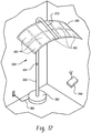
- Figure 17 demonstrates a floor lamp 260 that includes a base 262, ON/OFF switch 264, power supply cord 266, and an elongated support 268 that includes a bent over upper end 270.
- a larger panel 280 would likely use a larger matrix of individual light sources or OLED devices.
- a remote control 284 could be used to control the motor and likewise turn the lamp on and off. Further, the remote control could be used for dimming of the lamp.
- An exemplary desk or portable lamp includes a blue OLED having a light emitting surface area of approximately three square inches and two rectangular yellow OLEDs disposed on opposite sides of the blue OLED, where each yellow OLED has three light emitting surface areas that are approximately three -six square inches in surface area and each totaling approximately eighteen square inches as shown in Figures 1-6 .
- the total power for this lamp was less than 2.5 W.
- the color tuning was achieved from 3500K to 5600K by tuning or adjusting the power level of the blue OLED from about twenty percent (20%) of the power to one hundred percent (100%) of the power to a spot at a distance less than about three feet.
- the luminaire emits about fifty to one hundred fifty lumens at its maximum efficiency.
- an outcoupling film could be used to focus light in a forward direction where one preferred type of outcoupling film is sold by 3M under the tradename BEF2 or BEF3.
- one preferred type of outcoupling film is sold by 3M under the tradename BEF2 or BEF3.
- the OLED devices were driven with a DC power supply in series, it will be understood that the devices could also be driven individually. Parallel driving of the OLED devices is typically not preferred.
- luminaire 300 includes an elongated, thin, generally rectangular large area panel 302 (for example, on the order of 10 cm x 100 cm, or 20 cm x 100 cm).
- OLEDs 304, 306, 308 may be a single color or different colors, and by forming the OLED panel 302 and accompanying support structure 310 as thin layers, flexibility of the entire assembly may be achieved.
- a diffuser plate 312 preferably extends in closely spaced relation over the OLEDs and is supported along a perimeter edge 314 from the OLEDs.
- the diffuser plate 312 has a thickness less than 2 mm and is spaced from the OLEDs by a dimension that ranges from approximately 4 mm to 10 mm.
- the diffuser plate has a thickness greater than 2 mm and may be in direct contact with the OLED panel, however, this arrangement is slightly less efficient. In either case, the diffuser plate provides edge lighting as represented by the light ray traces 316 in Figures 20 and 21 .
- Figures 22-26 disclose variations of above-described concepts such as alternative locations of the OLEDs in the light emitting surface of the panel.
- end portions 330, 332 of the generally rectangular panel do not include any OLEDs, and instead the multiple OLEDs 334 are disposed along a central portion of the geometric shape of the panel.
- the embodiment of Figure 23 also locates a single large OLED or light emitting portion 336 of the panel in a central region and the end portions 340, 342 are devoid of any light emitting surface.
- central portion 350 does not include a light emitting member and instead the perimeter portions include elongated light emitting regions 352, 354 adjacent two edges and light emitting end regions 356, 358.
- Figure 25 adds to the arrangement of Figure 24 by including additional light from associated fiber optics (not shown) that illuminate all or some of an area of the flexible panel that includes a diffuser 360.
- the exemplary embodiment of Figure 26 uses a lens 370 or high index of refraction material such as glass to aid in directing light to a preferred location or to create a more uniform light throughout the flexible panel.
- a generally spherical-shaped surface 400 receives a flexible OLED panel 402 on a portion thereof. This illustrates that the OLED panel is generally flexible in more than one direction. Further, the spherical-shaped surface 400 may be selectively altered ( Figure 28 ) to change the light output from the panel. In addition, a selectively variable reflector surface(s) 404 may likewise be altered by changing the spherical-shaped surface 400 or by using an alternative mechanism to vary the shape of the surface. It is also contemplated that the spherical-shaped support surface 400 could be actively varied via a remote control.
- Structural material for the flexible luminaire can be a thin ductile metal, polymeric or elastomeric material.
- the structural material may be a plastic composite, i.e. a metal/carbon reinforced polymer composite having sufficient thermal conductivity (>1W/mk) to ensure heat dissipation of large panel luminaires.
- Preferred carbon can be carbon nanotube, graphene, graphene oxide or graphite with up to 50% filling.
- Typical metal can be Al, Sn, and Ni, etc.
Landscapes
- Engineering & Computer Science (AREA)
- General Engineering & Computer Science (AREA)
- Electroluminescent Light Sources (AREA)
- Non-Portable Lighting Devices Or Systems Thereof (AREA)
- Arrangement Of Elements, Cooling, Sealing, Or The Like Of Lighting Devices (AREA)
Description
- This disclosure is directed to a luminaire, and more particularly to a luminaire that uses a flexible surface light source such as solid state light source, particularly an organic light emitting device (OLED). Specifically, use of a solid state light source such as a light emitting device (LED) or an OLED offers a wide range of different applications.
- Recent developments with both LED and OLED light sources have come to fruition. As the lumen output of these structures has improved, there is a continuing need to develop new products and markets. Control of the light output is an important consideration, as well as color uniformity and color control. Further, simplified structures and applications that can advantageously use selected aspects of a solid state light source present new challenges with regard to function and cost. Consequently, a need exists to incorporate these design considerations into different lamp assemblies.
-
US 6 270 230 B1 discloses an umbrella with alert device including a circular umbrella cover made of waterproof material, an umbrella frame for supporting the umbrella cover to form an umbrella body, and an alert device for providing visual warning signal to others. -
WO 2010/004073 A1 discloses a tent with integrated lighting system, the tent comprising supporting elements for extending flexible lighting elements and a cover sheet to a concave formation. -
WO 2007/094810 A2 relates to methods and apparatus for high power factor power transfer to a load using a single switching stage, for example, a single stage high power factor driver to control power delivery to LED-based loads as light source. Each of the LED-based loads may include one or more LEDs of a same color. Different loads may include different color LEDs. The LED-based loads may include one or more "warm" white LEDs and one or more "cool" white LEDs so that by mixing different proportions of the warm and cool spectrums, a wide variety of intermediate color temperatures of white light may be generated. -
EP 1 783 532 A1 -
DE 299 13 930 U1 discloses a mobile lamp, comprising a screw and a spring for curving a carrier plate. - It is an object of the present invention to provide a novel LED and/or OLED based luminaire.
- The object is achieved by the features of the independent claim. Further embodiments are defined in the dependent claims.
- A primary benefit of this disclosure is the provision of a device with light directing capability.
- Another feature of the present disclosure relates to the ability to mix colors emitted from a flexible surface.
- Still another advantage resides in the ability to focus or diffuse the light emitted from the flexible surface.
- Still other benefits and advantages of the present disclosure will become more apparent from reading and understanding the following detailed description.
-
-
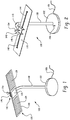
Figure 1 is a perspective view of a luminaire or lamp assembly incorporating at least one flexible light source. -
Figure 2 is a top perspective view of the luminaire ofFigure 1 . -
Figure 3 is a perspective view similar toFigure 2 illustrating a concave curvature of the conformal lamp. -
Figure 4 is a perspective view of the lamp ofFigure 3 generally illustrated from the underside. -
Figure 5 is a view similar toFigure 4 and illustrating a convex curvature of the conformal lamp. -
Figure 6 is an enlarged view of the conforming mechanism. -
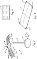
Figure 7 is a perspective view of a conformal lamp using LEDs. -
Figure 8 is a view of a blue OLED. -
Figure 9 is an enlarged view of the LED Portion of the lamp ofFigure 7 . -
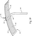
Figure 10 is a perspective view with first and second flexible lamp portions of the same color shown in a concave curvature. -
Figure 11 is a perspective view of a large panel OLED suspended from a stationary structure such as a ceiling. -
Figure 12 shows the large panel OLED ofFigure 11 in a concave configuration. -
Figure 13 shows the large panel OLED in a convex configuration. -
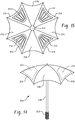
Figure 14 is a front view of an umbrella incorporating flexible light emitting panels. -
Figure 15 is a bottom view of the open umbrella ofFigure 14 more particularly illustrating location of light emitting panels. -
Figure 16 is a perspective view of an alternate free standing lamp assembly that has a predetermined curvature that may be selectively altered by the support legs. -
Figure 17 is a perspective view of a floor lamp using the OLED large panel. -
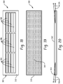
Figure 18 is a plan view of an OLED panel in another preferred embodiment. -
Figure 19 is a plan view of the OLED panel ofFigure 18 with a diffuser plate received over the OLED panel. -
Figure 20 is a front view of the OLED panel and diffuser plate assembly ofFigures 18 and 19 . -
Figure 21 illustrates light output from a desk lamp employing the OLED panel and diffuser plate assembly ofFigures 18-20 . -
Figures 22-24 are plan views of various locations of the OLED panel. -
Figures 25 and 26 are plan views of the OLED panel with light piped in to illuminate at least a portion of the panel. -
Figure 27 shows a flexible OLED panel disposed on a spherical-shaped surface. -
Figure 28 illustrates the luminaire ofFigure 27 with an adjustable reflector. -
Figures 1-6 illustrate a first preferred embodiment of a luminaire orlamp assembly 100. In this exemplary embodiment, thelamp assembly 100 includes arigid base 102 having an ON/OFF switch 104 or the ON/OFF switch could also be incorporated in to thepower supply cord 106. Extending from the base is a support orneck 108 which in the preferred arrangement is a rigid structure that is generally elongated and extends vertically above the base and is turned at anupper end 110. The upper end supports anelongated panel 120 formed of a thin material that is rigid with regard to its own weight and its rated load, but which can be conformed with an external force applied thereto. The panel preferably carries a solid statelight emitting device 122. In the illustrated embodiment ofFigures 1-6 , the light emitting device is intended for a small area of illumination, that is, on the order of less than one hundred square feet (100 ft2) per four (4) watt device by using flexible solid state panels such as OLED panels with greater than five (5) lux illumination. Multiple, flexibleOLED panel portions third panel portions central panel portion 126 emits a different color light, such as blue light. In order to have a flexible operation and provide a radius of curvature on the order of about five inches (5 in), an aspect ratio is from 1.0 to 1.8 with a thickness of less than five hundred micrometers (500µm). The total illuminating panel comprised of the three OLED panel portions may be on the order of approximately eighteen inches (18") in length and approximately four inches (4") in width. Due to its flexible operation, the thickness must be less than one millimeter (1mm) per one square meter (1m2) in order to reduce the potential for cracking in the device. Further, to reduce visible differentiation, the device can be covered with a diffuser material such as a fifty percent (50%) alumina, twenty percent (20%) titanium dioxide (TiO2) and thirty percent (30%) (LaMg)3(PO4)2 material, or a more preferable mixture is a titanium dioxide/alumina particle. - The blue
emitting panel portion 126 is preferably located in a central region to form a high color illumination area at the center. Further, the light level of the blue device allows for CCT control, i.e., color control from approximately 3,000K to 7,000K. On a surface of thepanel 120 opposite that of thelight emitting devices 122 is provided a conformingmechanism 140. By "conforming" is meant imparting a smoothly contoured, generally continuous shape, arc, or curvature to the panel portion. Conforming is contrasted with "bending", for example, which is deemed to be imparting a sharp crease, angle, or fold to the panel portion. The conforming mechanism imparts curving over the length of the panel, for example, first andsecond arms central actuator 146. The outer or distal ends of eacharm pins 148, while the proximal or inner ends of the arms include aspur gear 150 that engages with aworm gear 152. Selective rotation of the worm gear imparts rotary motion to the spur gears which are moved toward and away from the rotational axis of the central worm gear in response to the actuation or rotation. The direction of rotation of theworm gear 152 via actuating handle or key 154 extends or retracts the first and second arms to impart a curvature to the elongated panel. Alternatively, rather than a manual control of this rotation, a motor may be used to impart such actuation to the elongated flexible panel. - With continued reference to
Figures 1-6 , and additional reference to another preferred embodiment ofFigures 7-9 , many of the same components will be identified by the same reference numerals, and where differences occur, new reference numerals are used. For example, the first andthird panel portions individual LEDs 160 emit light which is then diffused by a cover ordome 162. The dome or translucent/transparent cover has a coating such as a phosphor for diffusing and emitting light over the entire surface of the dome rather than as individual point sources. Again, the first andthird panel portions central panel portion 126. It will also be recognized that with the embodiments of eitherFigures 1-6 orFigures 7-9 , the direction of rotation of the actuator will control whether thepanel 120, and particularly outer wing portions thereof, undertake a planar, convex, or concave conformation. The concave profile shown inFigures 3 and4 tends to concentrate light inward toward a remote location, while the convex profile ofFigure 5 diffuses light outwardly. Preferably, the wings are conformable up to a five inch (5") radius of curvature in both directions. - Moreover, using different colored light sources on the elongated end panels that are different from the central panel can control color mixing. For instance, a blue light source in the
central panel portion 126 and yellow light sources in the first and thirdlight panel portions -
Figure 10 is still another embodiment of the flexible luminaire or lamp assembly. Again, like reference numerals will refer to like components. The primary distinction is the elimination of a second panel portion of a different color. Thus, in this particular arrangement first and secondend panel portions perimeter frame 168 associated with the individual solid state light emitting devices. Nevertheless, the ability to impart a convex or concave conformation to theelongated panel 120 via the conformingmechanism 140 allows for the ability to concentrate light inwardly in the concave profile as shown inFigure 10 , or to diffuse light outwards if a convex profile (similar toFigure 5 ) is adopted. -
Figures 11-13 illustrate an OLEDlarge panel 200, shown suspended from a fixed structure such as aceiling 202. Again, the solid state light emitting device is a large panel and may be comprised of multiple OLED panels tiled or joined together in an array such as the rectangular configuration of theOLED panel 200. Here, different panel portions may be the same color or may be alternate colors. In this arrangement, one portion of the panel is rigidly secured, here, being suspended via first supports orsupport members 204. Thesefirst support members 204 are preferably non-adjustable. The first support members may be rigid members, or flexible wires that are extended to their full length to carry the weight of the OLED suspended from the ceiling. In this particular arrangement, the first support members support a first portion of the flexible surface, namely, a perimeter portion of the OLED panel. A second or adjustable member(s) 206 supports a second portion of the flexible surface. Here, the second,adjustable member 206 extends between theceiling 202 and the central portion of the flexible surface. In this manner, selected extension and retraction of the adjustable support(s) 206 conforms the OLED panel into a concave conformation (Figure 12 ) when the adjustable support is retracted or conforms to a convex shape as shown inFigure 13 when the adjustable support is extended. Thus, the embodiment ofFigures 11-13 illustrates a relatively simple configuration of a single convex or concave shape, although one skilled in the art will appreciate that different arrangements of non-adjustable support members and/or adjustable support members would allow alternative or more complex geometries to be achieved. - The embodiment of
Figures 14 and 15 shows an umbrella 210. Thehandle 212 may include a battery or similar portable power device that is used to power individual flexible light panel portions orlight surfaces 214 disposed insegments 216 on the umbrella surface. Particularly, the flexible light panel portions are located on the interior portions of the umbrella and are shown here as being located in every other flexible segment of the interior of the umbrella. Of course, this need not be the case, and a greater or lesser number of segments or portions of the umbrella segments may be used without departing from the scope and intent of the present disclosure. - In
Figure 16 , apanel 230 includes solid state light emittingdevices 232 such as OLEDs to emit light from at least one surface of the panel. In this arrangement, the panel has a predetermined curvature, i.e., when viewed from the floor as illustrated inFigure 16 , the panel has a generally convex contour. Anadjustable support 234 is provided to alter the curvature of the panel. For example, first and secondadjustable support members central region 240 to form an adjustable generally "x-shape" support. First or lower ends 242 of each of thesupport members slots 246, one slot preferably for each of the lower ends 242, and in which each slot has segmented, spaced stops 248 that allow each leg to be individually moved relative to the base, and engage against a new or different stop. This allows thelight emitting surface 232 to be tilted, and also allows the curvature of the panel to be altered. For example, if the dimension between the lower ends 242 is increased, then the curvature at the second or upper ends 250 will likewise be increased and spanningmembers 252 will likewise be spread apart. This reduces the curvature of the panel. In similar fashion, when the first ends 242 are brought closer to one another, then the second ends 252 likewise are brought closer together and the predetermined conformation of the panel allows the curvature to increase, i.e., become more convex. If one of the legs on each side is maintained against the same stop in the base while the position of the lower end of the other leg is altered, the curvature not only changes, but the tilt or angle of the panel. Consequently, the contour and angle of the light emitting surface will also be altered. -
Figure 17 demonstrates afloor lamp 260 that includes abase 262, ON/OFFswitch 264,power supply cord 266, and anelongated support 268 that includes a bent overupper end 270. Alarger panel 280 would likely use a larger matrix of individual light sources or OLED devices. Additionally, if a motor were implemented to control formability of the panel and light emitting surface thereof, aremote control 284 could be used to control the motor and likewise turn the lamp on and off. Further, the remote control could be used for dimming of the lamp. - An exemplary desk or portable lamp includes a blue OLED having a light emitting surface area of approximately three square inches and two rectangular yellow OLEDs disposed on opposite sides of the blue OLED, where each yellow OLED has three light emitting surface areas that are approximately three -six square inches in surface area and each totaling approximately eighteen square inches as shown in
Figures 1-6 . The total power for this lamp was less than 2.5 W. The color tuning was achieved from 3500K to 5600K by tuning or adjusting the power level of the blue OLED from about twenty percent (20%) of the power to one hundred percent (100%) of the power to a spot at a distance less than about three feet. The luminaire emits about fifty to one hundred fifty lumens at its maximum efficiency. Optionally, an outcoupling film could be used to focus light in a forward direction where one preferred type of outcoupling film is sold by 3M under the tradename BEF2 or BEF3. Although in the exemplary embodiment the OLED devices were driven with a DC power supply in series, it will be understood that the devices could also be driven individually. Parallel driving of the OLED devices is typically not preferred. - Shown in
Figures 18-21 is another preferred embodiment of a flexible luminaire that has many of the characteristics of previous embodiments. In this arrangement,luminaire 300 includes an elongated, thin, generally rectangular large area panel 302 (for example, on the order of 10 cm x 100 cm, or 20 cm x 100 cm). In the same manner as described in the prior embodiments,OLEDs OLED panel 302 and accompanyingsupport structure 310 as thin layers, flexibility of the entire assembly may be achieved. Here, adiffuser plate 312 preferably extends in closely spaced relation over the OLEDs and is supported along aperimeter edge 314 from the OLEDs. By way of example only, thediffuser plate 312 has a thickness less than 2 mm and is spaced from the OLEDs by a dimension that ranges from approximately 4 mm to 10 mm. On the other hand, in other embodiments the diffuser plate has a thickness greater than 2 mm and may be in direct contact with the OLED panel, however, this arrangement is slightly less efficient. In either case, the diffuser plate provides edge lighting as represented by the light ray traces 316 inFigures 20 and21 . -
Figures 22-26 disclose variations of above-described concepts such as alternative locations of the OLEDs in the light emitting surface of the panel. InFigure 22 ,end portions multiple OLEDs 334 are disposed along a central portion of the geometric shape of the panel. Similarly, the embodiment ofFigure 23 also locates a single large OLED orlight emitting portion 336 of the panel in a central region and theend portions Figure 24 , though,central portion 350 does not include a light emitting member and instead the perimeter portions include elongatedlight emitting regions end regions Figure 25 adds to the arrangement ofFigure 24 by including additional light from associated fiber optics (not shown) that illuminate all or some of an area of the flexible panel that includes adiffuser 360. Similarly, the exemplary embodiment ofFigure 26 uses alens 370 or high index of refraction material such as glass to aid in directing light to a preferred location or to create a more uniform light throughout the flexible panel. - In
Figure 27 , a generally spherical-shapedsurface 400 receives aflexible OLED panel 402 on a portion thereof. This illustrates that the OLED panel is generally flexible in more than one direction. Further, the spherical-shapedsurface 400 may be selectively altered (Figure 28 ) to change the light output from the panel. In addition, a selectively variable reflector surface(s) 404 may likewise be altered by changing the spherical-shapedsurface 400 or by using an alternative mechanism to vary the shape of the surface. It is also contemplated that the spherical-shapedsupport surface 400 could be actively varied via a remote control. - The disclosure has been described with respect to preferred embodiments. Obviously, modifications, alterations, and associated benefits may be contemplated by one skilled in the art. For example, although the proposed solutions find particular use in large area OLED devices that use electrical feed-through openings, selected aspects may also find application in OLED devices in general. Structural material for the flexible luminaire can be a thin ductile metal, polymeric or elastomeric material. Alternatively, the structural material may be a plastic composite, i.e. a metal/carbon reinforced polymer composite having sufficient thermal conductivity (>1W/mk) to ensure heat dissipation of large panel luminaires. Preferred carbon can be carbon nanotube, graphene, graphene oxide or graphite with up to 50% filling. Typical metal can be Al, Sn, and Ni, etc. The subject disclosure should not be limited to the particular examples described above but instead through the following claims.
Claims (12)
- A luminaire (100) comprising:a flexible surface (120);a solid state light emitting device (122) mounted to the surface, the light emitting device (122) including at least first and second panel portions (124, 128), the first and second panel portions (124, 128) being conformable; anda conforming mechanism (140) for curving the first and second panel portions (124, 128), characterized in thatthe conforming mechanism (140) includes first and second arms (142, 144) extending from a central actuator (146), the first and second arms (142, 144) secured at distal ends to the flexible surface (120),inner ends of the first and second arms (142, 144) each include a spur gear (150) that engages with a worm gear (152), androtation of the worm gear (152) imparts rotary motion to the spur gears (150) which extends or refracts the first and second arms (142, 144) to impart a concave curvature or a convex curvature to the first and second panel portions (124, 128).
- The luminaire (100) of claim 1 wherein the conforming mechanism (140) selectively curves the first and second panel portions (124, 128) into one of a planar conformation or an arcuate conformation.
- The luminaire (100) of claim 1 or claim 2, wherein the conforming mechanism (140) selectively curves the first and second panel portions (124, 128), from a first arcuate conformation to a second arcuate conformation having a greater degree of curvature than the first arcuate conformation.
- The luminaire (100) of claim 1, 2 or 3, wherein one of the first and second panel portions (124, 128) includes a light emitting diode, LED.
- The luminaire (100) of claim 4, wherein the LED includes multiple LEDs (160) in the first panel portion (124) enclosed by a translucent housing (162).
- The luminaire (100) of any preceding claim, wherein the first panel portion (124) is conformed relative to the second panel portion (128).
- The luminaire (100) of any preceding claim, further comprising a thin diffuser overlying at least a portion of the first panel portion (124) for directing light from an edge thereof.
- The luminaire (100) of any preceding claim, wherein the first and second panel portions (124,128) are organic light emitting devices, OLED.
- The luminaire (100) of any preceding claim, wherein the conforming mechanism (140) includes a threaded member for selectively altering a curvature of the first and second panel portions (124,128).
- The luminaire (100) of claim 9, wherein the flexible surface (120) is elongated.
- The luminaire (100) of any preceding claim, further comprising a central panel portion (126).
- The luminaire (100) of claim 11, wherein
the central panel portion (126) is centrally positioned between the first and second panel portions (124, 128) disposed on either side thereof, and/or
the central panel portion (126) emits blue light, and the first and second panel portions (124, 128) emit yellow light.
Applications Claiming Priority (2)
| Application Number | Priority Date | Filing Date | Title |
|---|---|---|---|
| US12/757,310 US8430530B2 (en) | 2010-04-09 | 2010-04-09 | Conformal OLED luminaire with color control |
| PCT/US2011/028054 WO2011126665A2 (en) | 2010-04-09 | 2011-03-11 | Conformal oled luminaire with color control |
Publications (2)
| Publication Number | Publication Date |
|---|---|
| EP2556295A2 EP2556295A2 (en) | 2013-02-13 |
| EP2556295B1 true EP2556295B1 (en) | 2017-10-04 |
Family
ID=44760785
Family Applications (1)
| Application Number | Title | Priority Date | Filing Date |
|---|---|---|---|
| EP11710083.4A Active EP2556295B1 (en) | 2010-04-09 | 2011-03-11 | Conformal oled luminaire with color control |
Country Status (6)
| Country | Link |
|---|---|
| US (1) | US8430530B2 (en) |
| EP (1) | EP2556295B1 (en) |
| JP (1) | JP5777699B2 (en) |
| KR (1) | KR101860959B1 (en) |
| CN (1) | CN102812291B (en) |
| WO (1) | WO2011126665A2 (en) |
Families Citing this family (103)
| Publication number | Priority date | Publication date | Assignee | Title |
|---|---|---|---|---|
| US8998462B2 (en) * | 2010-11-19 | 2015-04-07 | Tseng-Lu Chien | Multiple surface LED light |
| US20150354792A1 (en) | 2009-11-19 | 2015-12-10 | Tseng-Lu Chien | Interchange Universal Kits for LED Light Device |
| US8905610B2 (en) | 2009-01-26 | 2014-12-09 | Flex Lighting Ii, Llc | Light emitting device comprising a lightguide film |
| US10753598B2 (en) | 2010-11-19 | 2020-08-25 | Tseng-Lu Chien | Light device has charging functions |
| US20110157893A1 (en) * | 2009-12-28 | 2011-06-30 | Ngai Peter Y Y | Oled luminaire having observable surfaces with differential visual effects |
| US9651729B2 (en) | 2010-04-16 | 2017-05-16 | Flex Lighting Ii, Llc | Reflective display comprising a frontlight with extraction features and a light redirecting optical element |
| US20110310625A1 (en) * | 2010-06-16 | 2011-12-22 | Abl Ip Holding Llc | Light Fixtures Comprising Organic Light Emitting Diodes |
| DE202010008324U1 (en) * | 2010-08-10 | 2010-12-02 | Novaled Ag | Organic light device and lighting device |
| CN103313854A (en) * | 2010-11-02 | 2013-09-18 | 卡巴-诺塔赛斯有限公司 | Device for irradiating substrate material in the form of a sheet or web and uses thereof |
| WO2012068543A1 (en) | 2010-11-18 | 2012-05-24 | Flex Lighting Ii, Llc | Light emitting device comprising a lightguide film and aligned coupling lightguides |
| AU2012225244A1 (en) * | 2011-03-09 | 2013-10-03 | Flex Lighting Ii, Llc | Light emitting device with adjustable light output profile |
| US8624483B2 (en) | 2011-04-13 | 2014-01-07 | General Electric Company | Fixture and socket assembly for replaceable and flexible panel lighting device |
| US8884502B2 (en) * | 2011-07-25 | 2014-11-11 | General Electric Company | OLED assembly and luminaire with removable diffuser |
| US8764239B2 (en) * | 2011-08-16 | 2014-07-01 | Universal Display Corporation | Dynamic stretchable OLED lamp |
| JP5821583B2 (en) * | 2011-12-02 | 2015-11-24 | コニカミノルタ株式会社 | Lighting device |
| CN102518977A (en) * | 2011-12-16 | 2012-06-27 | 福建德泓勤上光电科技有限公司 | OLED (organic light emitting diode) eye-protecting desk lamp |
| NL2007980C2 (en) * | 2011-12-16 | 2013-06-18 | Dqm B V Nederland | Device and method to illuminate objects. |
| US9711752B2 (en) | 2011-12-19 | 2017-07-18 | Lg Electronics Inc. | Display apparatus |
| US9016894B2 (en) | 2012-03-09 | 2015-04-28 | General Electric Company | Color mixing using the reflective properties of OLEDs |
| JP2013206797A (en) * | 2012-03-29 | 2013-10-07 | Fujitsu Peripherals Ltd | Dome-shaped lighting device |
| KR101981717B1 (en) * | 2012-05-10 | 2019-05-24 | 엘지이노텍 주식회사 | Lighting device |
| CN102679233A (en) * | 2012-06-11 | 2012-09-19 | 海安县威仕重型机械有限公司 | LED (light-emitting diode) desk lamp with adjustable light source position |
| US10151464B2 (en) | 2012-09-18 | 2018-12-11 | Michael John Ahern | User-actuated lighting effect device |
| USD789896S1 (en) | 2015-11-11 | 2017-06-20 | Michael John Ahern | User-actuated lighting effect device |
| US9185776B2 (en) * | 2012-09-18 | 2015-11-10 | Michael John Ahern | User-actuated lighting effect device |
| TWI479108B (en) * | 2012-10-02 | 2015-04-01 | Lextar Electronics Corp | Light-emitting device for adjusting color temperature |
| US9899120B2 (en) | 2012-11-02 | 2018-02-20 | Nanotek Instruments, Inc. | Graphene oxide-coated graphitic foil and processes for producing same |
| KR20140101166A (en) * | 2013-02-08 | 2014-08-19 | 엘지전자 주식회사 | Display apparatus |
| US10087073B2 (en) | 2013-02-14 | 2018-10-02 | Nanotek Instruments, Inc. | Nano graphene platelet-reinforced composite heat sinks and process for producing same |
| US9690032B1 (en) | 2013-03-12 | 2017-06-27 | Flex Lighting Ii Llc | Lightguide including a film with one or more bends |
| US11009646B2 (en) | 2013-03-12 | 2021-05-18 | Azumo, Inc. | Film-based lightguide with interior light directing edges in a light mixing region |
| KR102046927B1 (en) * | 2013-04-18 | 2019-12-04 | 엘지전자 주식회사 | Display apparatus |
| JP2014232156A (en) * | 2013-05-28 | 2014-12-11 | コニカミノルタ株式会社 | Reflection member and surface light emission unit |
| JP6131719B2 (en) * | 2013-05-28 | 2017-05-24 | コニカミノルタ株式会社 | Reflecting member, manufacturing method thereof, and surface emitting unit |
| KR101989989B1 (en) * | 2013-06-20 | 2019-06-17 | 엘지전자 주식회사 | Display apparatus |
| EP2818787A1 (en) * | 2013-06-26 | 2014-12-31 | Chao-Chin Yeh | Arc led lamp |
| KR102091517B1 (en) * | 2013-07-02 | 2020-03-20 | 엘지전자 주식회사 | Image display device |
| USD713589S1 (en) * | 2013-08-30 | 2014-09-16 | Abl Ip Holding, Llc | Wall mounted lighting fixture |
| USD742582S1 (en) * | 2013-08-30 | 2015-11-03 | Abl Ip Holding, Llc | Wall mounted lighting fixture |
| USD713591S1 (en) * | 2013-08-30 | 2014-09-16 | Abl Ip Holding, Llc | Wall mounted lighting fixture |
| JP2015050157A (en) * | 2013-09-04 | 2015-03-16 | コニカミノルタ株式会社 | Organic electroluminescent illuminating device |
| US20150062901A1 (en) * | 2013-09-04 | 2015-03-05 | Te-Lung Chen | Flexible Power Strip for Lamp |
| US9869456B2 (en) * | 2013-11-08 | 2018-01-16 | Osram Sylvania Inc. | Fixture design for flexible LED circuit boards |
| JPWO2015118932A1 (en) * | 2014-02-10 | 2017-03-23 | コニカミノルタ株式会社 | Organic electroluminescence lighting device and lighting method |
| JPWO2015118919A1 (en) * | 2014-02-10 | 2017-03-23 | コニカミノルタ株式会社 | Organic electroluminescence lighting device |
| CA2843099A1 (en) * | 2014-02-20 | 2015-08-20 | Matthew Kennedy | Luminaire assembly with suspension point over center of mass that is not vertically in-line with major axis of shade |
| WO2015155663A1 (en) * | 2014-04-11 | 2015-10-15 | Semiconductor Energy Laboratory Co., Ltd. | Light-emitting device |
| USD740993S1 (en) | 2014-05-20 | 2015-10-13 | Abl Ip Holding, Llc | Luminaire |
| USD745735S1 (en) * | 2014-05-30 | 2015-12-15 | Abl Ip Holding, Llc | Luminaire |
| USD743087S1 (en) * | 2014-05-30 | 2015-11-10 | Abl Ip Holding, Llc | Luminaire |
| USD743086S1 (en) | 2014-05-30 | 2015-11-10 | Abl Ip Holding, Llc | Luminaire |
| USD730560S1 (en) | 2014-05-30 | 2015-05-26 | Abl Ip Holding, Llc | Luminaire |
| USD742576S1 (en) * | 2014-05-30 | 2015-11-03 | Abl Ip Holding, Llc | Luminaire |
| USD724250S1 (en) | 2014-05-30 | 2015-03-10 | Abl Ip Holding, Llc | Luminaire |
| US9360887B2 (en) * | 2014-06-09 | 2016-06-07 | Shenzhen China Star Optoelectronics Technology Co., Ltd | Display device |
| US20150360271A1 (en) * | 2014-06-12 | 2015-12-17 | James Bradford Hawkins | Curved light emitting diode fixture |
| TWI557365B (en) * | 2014-06-27 | 2016-11-11 | Lamp and its operation method | |
| ES2532051B1 (en) * | 2014-08-05 | 2016-01-04 | The Mad Pixel Factory S.L. | LED lighting device |
| JP6330104B2 (en) * | 2014-09-03 | 2018-05-23 | エルジー ディスプレイ カンパニー リミテッド | Multipurpose auxiliary lamp |
| WO2016042982A1 (en) * | 2014-09-16 | 2016-03-24 | コニカミノルタ株式会社 | Light emitting device |
| USD732227S1 (en) * | 2014-10-24 | 2015-06-16 | Abl Ip Holding, Llc | Luminaire |
| CN104464530B (en) * | 2014-11-18 | 2017-08-25 | 深圳市华星光电技术有限公司 | Curved face type display device |
| CN104806910B (en) * | 2015-04-30 | 2017-10-17 | 东莞勤上光电股份有限公司 | A kind of LED/light source module of adjustable overall light divergence |
| USD760942S1 (en) | 2015-05-01 | 2016-07-05 | Abl Ip Holding, Llc | Luminaire |
| USD742575S1 (en) * | 2015-05-01 | 2015-11-03 | Abl Ip Holding, Llc | Luminaire |
| USD763496S1 (en) | 2015-05-01 | 2016-08-09 | Abl Ip Holding, Llc | Luminaire |
| USD762911S1 (en) | 2015-05-01 | 2016-08-02 | Abl Ip Holding, Llc | Luminaire |
| USD759876S1 (en) * | 2015-05-01 | 2016-06-21 | Abl Ip Holding, Llc | Luminaire |
| USD760426S1 (en) | 2015-05-01 | 2016-06-28 | Abl Ip Holding, Llc | Luminaire |
| KR102353426B1 (en) * | 2015-05-27 | 2022-01-20 | 엘지디스플레이 주식회사 | Display device |
| DE102015110242A1 (en) * | 2015-06-25 | 2016-12-29 | Osram Oled Gmbh | lamp |
| CN105258038A (en) * | 2015-11-20 | 2016-01-20 | 苏州铭冠软件科技有限公司 | Sound-control concave-surface OLED (organic light emitting diode) spotlight |
| CN105605436A (en) * | 2015-11-20 | 2016-05-25 | 苏州铭冠软件科技有限公司 | Induction type concave surface OLED spot light |
| CN105299572A (en) * | 2015-11-20 | 2016-02-03 | 苏州铭冠软件科技有限公司 | Waterproof concave face OLED spotlight |
| CN105333315A (en) * | 2015-11-20 | 2016-02-17 | 苏州铭冠软件科技有限公司 | Sound-light double-controlled concave surface OLED (Organic Light Emitting Diode) spotlight |
| CN105276421A (en) * | 2015-11-20 | 2016-01-27 | 苏州铭冠软件科技有限公司 | Concave surface OLED spot light |
| CN105258066A (en) * | 2015-11-20 | 2016-01-20 | 苏州铭冠软件科技有限公司 | Energy-saved and environment-friendly concave surface OLED spotlight |
| KR102483559B1 (en) * | 2015-12-28 | 2023-01-02 | 엘지디스플레이 주식회사 | Display device |
| KR102429119B1 (en) * | 2015-12-30 | 2022-08-05 | 엘지디스플레이 주식회사 | Display device |
| KR101858702B1 (en) * | 2015-12-30 | 2018-05-16 | 엘지전자 주식회사 | Lamp apparatus for Vehicles |
| CN107438739A (en) * | 2016-04-15 | 2017-12-05 | 深圳市柔宇科技有限公司 | Lighting device |
| CN106051568A (en) * | 2016-06-27 | 2016-10-26 | 安庆市奥立德光电有限公司 | Telescopic LED lamp |
| DE202016103453U1 (en) * | 2016-06-29 | 2017-10-06 | Emdedesign Gmbh | Luminaire comprising a flexible OLED illuminant |
| KR101921517B1 (en) * | 2016-07-22 | 2018-11-23 | 김선권 | LED Lighting Device |
| US10637005B2 (en) | 2016-08-26 | 2020-04-28 | Osram Oled Gmbh | Method of producing a component module and component module |
| US10409080B2 (en) * | 2017-02-01 | 2019-09-10 | Facebook Technologies, Llc | Spherical display using flexible substrates |
| US10989394B2 (en) * | 2018-01-09 | 2021-04-27 | OLEDWorks LLC | Thin OLED lighting module |
| WO2019137941A1 (en) * | 2018-01-09 | 2019-07-18 | Oledworks Gmbh | Ultrathin oled lighting panel |
| CN108302290B (en) * | 2018-01-12 | 2019-07-26 | 惠州市华星光电技术有限公司 | Variable curve supporting structure |
| KR102476295B1 (en) * | 2018-01-31 | 2022-12-09 | 엘지전자 주식회사 | Display device |
| CN109000203B (en) | 2018-07-25 | 2020-07-31 | 京东方科技集团股份有限公司 | a headlight |
| KR20180092926A (en) | 2018-08-13 | 2018-08-20 | 한국광기술원 | Angular distribution of luminous intensity variable type lighting module and lighting device using the same |
| US11994698B2 (en) | 2018-08-30 | 2024-05-28 | Azumo, Inc. | Film-based frontlight with angularly varying diffusion film |
| EP3894917A4 (en) | 2018-12-11 | 2022-07-13 | Azumo, Inc. | FRONT LIGHTING LIGHT GUIDE WITH DIFFUSE REFLECTIVE SEPARATOR |
| WO2020142731A1 (en) | 2019-01-03 | 2020-07-09 | Flex Lighting Ii, Llc | Reflective display comprising a lightguide and light turning film creating multiple illumination peaks |
| CN113678036B (en) | 2019-01-09 | 2024-02-02 | 阿祖莫公司 | Reflective display including coupled light guides folded at different folding angles |
| WO2021022307A1 (en) | 2019-08-01 | 2021-02-04 | Flex Lighting Ii, Llc | Lightguide with a light input edge between lateral edges of a folded strip |
| USD943133S1 (en) * | 2019-12-17 | 2022-02-08 | Hangzhou Junction Imp. & Exp. Co., Ltd. | Plant light |
| USD960427S1 (en) * | 2020-05-01 | 2022-08-09 | Lilac and Lemon LLC | Light for cosmetic application |
| US12571956B2 (en) | 2020-09-29 | 2026-03-10 | Azumo, Inc. | Manufacturing a lightguide with cut lateral edges |
| US12453275B2 (en) | 2021-05-07 | 2025-10-21 | Semiconductor Energy Laboratory Co., Ltd. | Display apparatus |
| KR20230038937A (en) * | 2021-09-13 | 2023-03-21 | 엘지전자 주식회사 | Display device |
| CN113864696B (en) * | 2021-09-30 | 2024-06-11 | 深圳市耐锐科技有限公司 | Outdoor floor lamp |
Citations (13)
| Publication number | Priority date | Publication date | Assignee | Title |
|---|---|---|---|---|
| US4601120A (en) * | 1984-11-09 | 1986-07-22 | Levin William J | Flexible illuminated display |
| US5752766A (en) * | 1997-03-11 | 1998-05-19 | Bailey; James Tam | Multi-color focusable LED stage light |
| DE29913930U1 (en) * | 1999-08-13 | 1999-11-18 | Strobl, Thomas, 82541 Münsing | Mobile lamp |
| US6270230B1 (en) * | 1998-09-03 | 2001-08-07 | Kuei Ying Mai | Umbrella with alert device |
| DE10102613A1 (en) * | 2001-01-21 | 2002-07-25 | Aloysius Wolf | Focusing device for light emitting diodes of illuminating devices, has base plate on which light emitting diodes sit that can be displaced in convex or concave manner |
| US20050110702A1 (en) * | 2003-11-21 | 2005-05-26 | Aoki Paul M. | Collapsible display device and methods for using the same |
| DE102005003633A1 (en) * | 2005-01-24 | 2006-08-03 | Matthias Lang | Light dispersing and concentrating device for e.g. motor vehicle headlight, has flexible matrix achieving concave or convex shape due to effect of forces so that lights emitted from sources as concentrated at common point or are dispersed |
| EP1783532A1 (en) * | 2005-11-03 | 2007-05-09 | SFIR (Société Financière et de Réalisation ) | Beleuchtungseinheit mit streifendem Einfall |
| WO2007094810A2 (en) * | 2006-02-10 | 2007-08-23 | Color Kinetics Incorporated | Methods and apparatus for high power factor controlled power delivery using a single switching stage per load |
| WO2008060469A2 (en) * | 2006-11-10 | 2008-05-22 | Philips Solid-State Lighting Solutions, Inc. | Methods and apparatus for controlling series-connected leds |
| WO2010004073A1 (en) * | 2008-07-07 | 2010-01-14 | Fundación Privada Cetemmsa | Tent with integrated lighting system |
| US20100046210A1 (en) * | 2008-08-19 | 2010-02-25 | Plextronics, Inc. | Organic light emitting diode products |
| US20100045189A1 (en) * | 2008-08-19 | 2010-02-25 | Plextronics, Inc. | Organic light emitting diode lighting systems |
Family Cites Families (16)
| Publication number | Priority date | Publication date | Assignee | Title |
|---|---|---|---|---|
| JPS61126510U (en) * | 1985-01-25 | 1986-08-08 | ||
| US5580163A (en) | 1994-07-20 | 1996-12-03 | August Technology Corporation | Focusing light source with flexible mount for multiple light-emitting elements |
| JP2001250419A (en) * | 2000-03-03 | 2001-09-14 | Rabo Sufia Kk | Lighting equipment |
| JP4067802B2 (en) | 2001-09-18 | 2008-03-26 | 松下電器産業株式会社 | Lighting device |
| US6776496B2 (en) | 2002-08-19 | 2004-08-17 | Eastman Kodak Company | Area illumination lighting apparatus having OLED planar light source |
| US7455444B2 (en) | 2004-07-06 | 2008-11-25 | Tseng-Lu Chien | Multiple light source night light |
| US7465678B2 (en) | 2003-03-28 | 2008-12-16 | The Trustees Of Princeton University | Deformable organic devices |
| US20060083004A1 (en) | 2004-10-15 | 2006-04-20 | Eastman Kodak Company | Flat-panel area illumination system |
| US7375473B2 (en) | 2005-04-15 | 2008-05-20 | Eastman Kodak Company | Variable power control for OLED area illumination |
| US7575332B2 (en) | 2005-06-21 | 2009-08-18 | Eastman Kodak Company | Removable flat-panel lamp and fixture |
| KR101217554B1 (en) | 2006-05-09 | 2013-01-02 | 삼성전자주식회사 | seamless foldable display device |
| US20080007936A1 (en) | 2006-07-05 | 2008-01-10 | Jie Liu | Organic illumination source and method for controlled illumination |
| JP4293314B2 (en) * | 2007-01-26 | 2009-07-08 | 財団法人山形県産業技術振興機構 | Lighting device |
| CN101387785A (en) * | 2007-09-11 | 2009-03-18 | 苏州璨宇光学有限公司 | Backlight module |
| JP4540005B2 (en) * | 2008-02-29 | 2010-09-08 | 財団法人山形県産業技術振興機構 | Lighting device |
| JP5140500B2 (en) * | 2008-06-25 | 2013-02-06 | パナソニック株式会社 | lighting equipment |
-
2010
- 2010-04-09 US US12/757,310 patent/US8430530B2/en active Active
-
2011
- 2011-03-11 EP EP11710083.4A patent/EP2556295B1/en active Active
- 2011-03-11 WO PCT/US2011/028054 patent/WO2011126665A2/en not_active Ceased
- 2011-03-11 CN CN201180018165.6A patent/CN102812291B/en active Active
- 2011-03-11 KR KR1020127026223A patent/KR101860959B1/en active Active
- 2011-03-11 JP JP2013503754A patent/JP5777699B2/en active Active
Patent Citations (13)
| Publication number | Priority date | Publication date | Assignee | Title |
|---|---|---|---|---|
| US4601120A (en) * | 1984-11-09 | 1986-07-22 | Levin William J | Flexible illuminated display |
| US5752766A (en) * | 1997-03-11 | 1998-05-19 | Bailey; James Tam | Multi-color focusable LED stage light |
| US6270230B1 (en) * | 1998-09-03 | 2001-08-07 | Kuei Ying Mai | Umbrella with alert device |
| DE29913930U1 (en) * | 1999-08-13 | 1999-11-18 | Strobl, Thomas, 82541 Münsing | Mobile lamp |
| DE10102613A1 (en) * | 2001-01-21 | 2002-07-25 | Aloysius Wolf | Focusing device for light emitting diodes of illuminating devices, has base plate on which light emitting diodes sit that can be displaced in convex or concave manner |
| US20050110702A1 (en) * | 2003-11-21 | 2005-05-26 | Aoki Paul M. | Collapsible display device and methods for using the same |
| DE102005003633A1 (en) * | 2005-01-24 | 2006-08-03 | Matthias Lang | Light dispersing and concentrating device for e.g. motor vehicle headlight, has flexible matrix achieving concave or convex shape due to effect of forces so that lights emitted from sources as concentrated at common point or are dispersed |
| EP1783532A1 (en) * | 2005-11-03 | 2007-05-09 | SFIR (Société Financière et de Réalisation ) | Beleuchtungseinheit mit streifendem Einfall |
| WO2007094810A2 (en) * | 2006-02-10 | 2007-08-23 | Color Kinetics Incorporated | Methods and apparatus for high power factor controlled power delivery using a single switching stage per load |
| WO2008060469A2 (en) * | 2006-11-10 | 2008-05-22 | Philips Solid-State Lighting Solutions, Inc. | Methods and apparatus for controlling series-connected leds |
| WO2010004073A1 (en) * | 2008-07-07 | 2010-01-14 | Fundación Privada Cetemmsa | Tent with integrated lighting system |
| US20100046210A1 (en) * | 2008-08-19 | 2010-02-25 | Plextronics, Inc. | Organic light emitting diode products |
| US20100045189A1 (en) * | 2008-08-19 | 2010-02-25 | Plextronics, Inc. | Organic light emitting diode lighting systems |
Also Published As
| Publication number | Publication date |
|---|---|
| WO2011126665A2 (en) | 2011-10-13 |
| US8430530B2 (en) | 2013-04-30 |
| CN102812291A (en) | 2012-12-05 |
| CN102812291B (en) | 2016-02-24 |
| KR101860959B1 (en) | 2018-07-05 |
| EP2556295A2 (en) | 2013-02-13 |
| WO2011126665A3 (en) | 2012-04-12 |
| KR20130041781A (en) | 2013-04-25 |
| US20110249425A1 (en) | 2011-10-13 |
| JP2013528897A (en) | 2013-07-11 |
| JP5777699B2 (en) | 2015-09-09 |
Similar Documents
| Publication | Publication Date | Title |
|---|---|---|
| US8430530B2 (en) | Conformal OLED luminaire with color control | |
| AU2011243504B2 (en) | Surface illumination fixture and surface illumination device | |
| US7712926B2 (en) | Luminaire comprising adjustable light modules | |
| US7591572B1 (en) | Compact lighting device | |
| US8807792B2 (en) | Lighting apparatus | |
| US8235554B2 (en) | LED reflector fixture | |
| US11719419B1 (en) | Deformable light emitting diode (LED) lamp configured to change light emitting angle by folding | |
| KR20100017616A (en) | Light fixtures and lighting devices | |
| US10012354B2 (en) | Adjustable retrofit LED troffer | |
| KR101115562B1 (en) | Lighting apparatus | |
| WO2010140490A1 (en) | Led illuminating device | |
| KR200455985Y1 (en) | LED lighting lamp | |
| CN215808082U (en) | Deformable folding LED lamp capable of changing light emitting angle | |
| JP3177650U (en) | LED lighting device | |
| KR102703358B1 (en) | An apparatus for optical irradiation for medical use with a variable mode under motor control | |
| CN214664274U (en) | An adjustable LED lamp | |
| CN221611189U (en) | Lighting assembly and lighting device | |
| CN221592787U (en) | Lamp set | |
| KR101282128B1 (en) | LED lamp with reflector | |
| CN223795116U (en) | Lighting fixtures | |
| CN220524064U (en) | Mounting shell structure of LED lamp tube | |
| CN215174539U (en) | High-power ceiling lamp with variable illumination angle | |
| CN113310004A (en) | Method and lamp capable of adjusting light-emitting angle | |
| EP3382262B1 (en) | Lighting lamp | |
| JP2008016314A (en) | Light source using LED and lighting device using the same |
Legal Events
| Date | Code | Title | Description |
|---|---|---|---|
| PUAI | Public reference made under article 153(3) epc to a published international application that has entered the european phase |
Free format text: ORIGINAL CODE: 0009012 |
|
| 17P | Request for examination filed |
Effective date: 20121109 |
|
| AK | Designated contracting states |
Kind code of ref document: A2 Designated state(s): AL AT BE BG CH CY CZ DE DK EE ES FI FR GB GR HR HU IE IS IT LI LT LU LV MC MK MT NL NO PL PT RO RS SE SI SK SM TR |
|
| DAX | Request for extension of the european patent (deleted) | ||
| RAP1 | Party data changed (applicant data changed or rights of an application transferred) |
Owner name: BOE TECHNOLOGY GROUP CO., LTD. |
|
| STAA | Information on the status of an ep patent application or granted ep patent |
Free format text: STATUS: EXAMINATION IS IN PROGRESS |
|
| 17Q | First examination report despatched |
Effective date: 20161108 |
|
| GRAP | Despatch of communication of intention to grant a patent |
Free format text: ORIGINAL CODE: EPIDOSNIGR1 |
|
| STAA | Information on the status of an ep patent application or granted ep patent |
Free format text: STATUS: GRANT OF PATENT IS INTENDED |
|
| INTG | Intention to grant announced |
Effective date: 20170424 |
|
| GRAA | (expected) grant |
Free format text: ORIGINAL CODE: 0009210 |
|
| GRAS | Grant fee paid |
Free format text: ORIGINAL CODE: EPIDOSNIGR3 |
|
| STAA | Information on the status of an ep patent application or granted ep patent |
Free format text: STATUS: THE PATENT HAS BEEN GRANTED |
|
| AK | Designated contracting states |
Kind code of ref document: B1 Designated state(s): AL AT BE BG CH CY CZ DE DK EE ES FI FR GB GR HR HU IE IS IT LI LT LU LV MC MK MT NL NO PL PT RO RS SE SI SK SM TR |
|
| REG | Reference to a national code |
Ref country code: GB Ref legal event code: FG4D |
|
| REG | Reference to a national code |
Ref country code: CH Ref legal event code: EP |
|
| REG | Reference to a national code |
Ref country code: AT Ref legal event code: REF Ref document number: 934402 Country of ref document: AT Kind code of ref document: T Effective date: 20171015 |
|
| REG | Reference to a national code |
Ref country code: IE Ref legal event code: FG4D |
|
| REG | Reference to a national code |
Ref country code: DE Ref legal event code: R096 Ref document number: 602011042087 Country of ref document: DE |
|
| REG | Reference to a national code |
Ref country code: NL Ref legal event code: FP |
|
| REG | Reference to a national code |
Ref country code: FR Ref legal event code: PLFP Year of fee payment: 8 |
|
| REG | Reference to a national code |
Ref country code: LT Ref legal event code: MG4D |
|
| REG | Reference to a national code |
Ref country code: AT Ref legal event code: MK05 Ref document number: 934402 Country of ref document: AT Kind code of ref document: T Effective date: 20171004 |
|
| PG25 | Lapsed in a contracting state [announced via postgrant information from national office to epo] |
Ref country code: LT Free format text: LAPSE BECAUSE OF FAILURE TO SUBMIT A TRANSLATION OF THE DESCRIPTION OR TO PAY THE FEE WITHIN THE PRESCRIBED TIME-LIMIT Effective date: 20171004 Ref country code: SE Free format text: LAPSE BECAUSE OF FAILURE TO SUBMIT A TRANSLATION OF THE DESCRIPTION OR TO PAY THE FEE WITHIN THE PRESCRIBED TIME-LIMIT Effective date: 20171004 Ref country code: NO Free format text: LAPSE BECAUSE OF FAILURE TO SUBMIT A TRANSLATION OF THE DESCRIPTION OR TO PAY THE FEE WITHIN THE PRESCRIBED TIME-LIMIT Effective date: 20180104 Ref country code: ES Free format text: LAPSE BECAUSE OF FAILURE TO SUBMIT A TRANSLATION OF THE DESCRIPTION OR TO PAY THE FEE WITHIN THE PRESCRIBED TIME-LIMIT Effective date: 20171004 Ref country code: FI Free format text: LAPSE BECAUSE OF FAILURE TO SUBMIT A TRANSLATION OF THE DESCRIPTION OR TO PAY THE FEE WITHIN THE PRESCRIBED TIME-LIMIT Effective date: 20171004 |
|
| PG25 | Lapsed in a contracting state [announced via postgrant information from national office to epo] |
Ref country code: IS Free format text: LAPSE BECAUSE OF FAILURE TO SUBMIT A TRANSLATION OF THE DESCRIPTION OR TO PAY THE FEE WITHIN THE PRESCRIBED TIME-LIMIT Effective date: 20180204 Ref country code: GR Free format text: LAPSE BECAUSE OF FAILURE TO SUBMIT A TRANSLATION OF THE DESCRIPTION OR TO PAY THE FEE WITHIN THE PRESCRIBED TIME-LIMIT Effective date: 20180105 Ref country code: RS Free format text: LAPSE BECAUSE OF FAILURE TO SUBMIT A TRANSLATION OF THE DESCRIPTION OR TO PAY THE FEE WITHIN THE PRESCRIBED TIME-LIMIT Effective date: 20171004 Ref country code: BG Free format text: LAPSE BECAUSE OF FAILURE TO SUBMIT A TRANSLATION OF THE DESCRIPTION OR TO PAY THE FEE WITHIN THE PRESCRIBED TIME-LIMIT Effective date: 20180104 Ref country code: HR Free format text: LAPSE BECAUSE OF FAILURE TO SUBMIT A TRANSLATION OF THE DESCRIPTION OR TO PAY THE FEE WITHIN THE PRESCRIBED TIME-LIMIT Effective date: 20171004 Ref country code: LV Free format text: LAPSE BECAUSE OF FAILURE TO SUBMIT A TRANSLATION OF THE DESCRIPTION OR TO PAY THE FEE WITHIN THE PRESCRIBED TIME-LIMIT Effective date: 20171004 Ref country code: AT Free format text: LAPSE BECAUSE OF FAILURE TO SUBMIT A TRANSLATION OF THE DESCRIPTION OR TO PAY THE FEE WITHIN THE PRESCRIBED TIME-LIMIT Effective date: 20171004 |
|
| REG | Reference to a national code |
Ref country code: DE Ref legal event code: R097 Ref document number: 602011042087 Country of ref document: DE |
|
| PG25 | Lapsed in a contracting state [announced via postgrant information from national office to epo] |
Ref country code: CZ Free format text: LAPSE BECAUSE OF FAILURE TO SUBMIT A TRANSLATION OF THE DESCRIPTION OR TO PAY THE FEE WITHIN THE PRESCRIBED TIME-LIMIT Effective date: 20171004 Ref country code: EE Free format text: LAPSE BECAUSE OF FAILURE TO SUBMIT A TRANSLATION OF THE DESCRIPTION OR TO PAY THE FEE WITHIN THE PRESCRIBED TIME-LIMIT Effective date: 20171004 Ref country code: SK Free format text: LAPSE BECAUSE OF FAILURE TO SUBMIT A TRANSLATION OF THE DESCRIPTION OR TO PAY THE FEE WITHIN THE PRESCRIBED TIME-LIMIT Effective date: 20171004 Ref country code: DK Free format text: LAPSE BECAUSE OF FAILURE TO SUBMIT A TRANSLATION OF THE DESCRIPTION OR TO PAY THE FEE WITHIN THE PRESCRIBED TIME-LIMIT Effective date: 20171004 |
|
| PLBE | No opposition filed within time limit |
Free format text: ORIGINAL CODE: 0009261 |
|
| STAA | Information on the status of an ep patent application or granted ep patent |
Free format text: STATUS: NO OPPOSITION FILED WITHIN TIME LIMIT |
|
| PG25 | Lapsed in a contracting state [announced via postgrant information from national office to epo] |
Ref country code: IT Free format text: LAPSE BECAUSE OF FAILURE TO SUBMIT A TRANSLATION OF THE DESCRIPTION OR TO PAY THE FEE WITHIN THE PRESCRIBED TIME-LIMIT Effective date: 20171004 Ref country code: RO Free format text: LAPSE BECAUSE OF FAILURE TO SUBMIT A TRANSLATION OF THE DESCRIPTION OR TO PAY THE FEE WITHIN THE PRESCRIBED TIME-LIMIT Effective date: 20171004 Ref country code: PL Free format text: LAPSE BECAUSE OF FAILURE TO SUBMIT A TRANSLATION OF THE DESCRIPTION OR TO PAY THE FEE WITHIN THE PRESCRIBED TIME-LIMIT Effective date: 20171004 Ref country code: SM Free format text: LAPSE BECAUSE OF FAILURE TO SUBMIT A TRANSLATION OF THE DESCRIPTION OR TO PAY THE FEE WITHIN THE PRESCRIBED TIME-LIMIT Effective date: 20171004 |
|
| 26N | No opposition filed |
Effective date: 20180705 |
|
| REG | Reference to a national code |
Ref country code: CH Ref legal event code: PL |
|
| PG25 | Lapsed in a contracting state [announced via postgrant information from national office to epo] |
Ref country code: SI Free format text: LAPSE BECAUSE OF FAILURE TO SUBMIT A TRANSLATION OF THE DESCRIPTION OR TO PAY THE FEE WITHIN THE PRESCRIBED TIME-LIMIT Effective date: 20171004 Ref country code: MC Free format text: LAPSE BECAUSE OF FAILURE TO SUBMIT A TRANSLATION OF THE DESCRIPTION OR TO PAY THE FEE WITHIN THE PRESCRIBED TIME-LIMIT Effective date: 20171004 |
|
| REG | Reference to a national code |
Ref country code: BE Ref legal event code: MM Effective date: 20180331 |
|
| REG | Reference to a national code |
Ref country code: IE Ref legal event code: MM4A |
|
| PG25 | Lapsed in a contracting state [announced via postgrant information from national office to epo] |
Ref country code: LU Free format text: LAPSE BECAUSE OF NON-PAYMENT OF DUE FEES Effective date: 20180311 |
|
| PG25 | Lapsed in a contracting state [announced via postgrant information from national office to epo] |
Ref country code: IE Free format text: LAPSE BECAUSE OF NON-PAYMENT OF DUE FEES Effective date: 20180311 |
|
| PG25 | Lapsed in a contracting state [announced via postgrant information from national office to epo] |
Ref country code: BE Free format text: LAPSE BECAUSE OF NON-PAYMENT OF DUE FEES Effective date: 20180331 Ref country code: CH Free format text: LAPSE BECAUSE OF NON-PAYMENT OF DUE FEES Effective date: 20180331 Ref country code: LI Free format text: LAPSE BECAUSE OF NON-PAYMENT OF DUE FEES Effective date: 20180331 |
|
| PG25 | Lapsed in a contracting state [announced via postgrant information from national office to epo] |
Ref country code: MT Free format text: LAPSE BECAUSE OF NON-PAYMENT OF DUE FEES Effective date: 20180311 |
|
| PG25 | Lapsed in a contracting state [announced via postgrant information from national office to epo] |
Ref country code: TR Free format text: LAPSE BECAUSE OF FAILURE TO SUBMIT A TRANSLATION OF THE DESCRIPTION OR TO PAY THE FEE WITHIN THE PRESCRIBED TIME-LIMIT Effective date: 20171004 |
|
| PG25 | Lapsed in a contracting state [announced via postgrant information from national office to epo] |
Ref country code: PT Free format text: LAPSE BECAUSE OF FAILURE TO SUBMIT A TRANSLATION OF THE DESCRIPTION OR TO PAY THE FEE WITHIN THE PRESCRIBED TIME-LIMIT Effective date: 20171004 Ref country code: HU Free format text: LAPSE BECAUSE OF FAILURE TO SUBMIT A TRANSLATION OF THE DESCRIPTION OR TO PAY THE FEE WITHIN THE PRESCRIBED TIME-LIMIT; INVALID AB INITIO Effective date: 20110311 |
|
| PG25 | Lapsed in a contracting state [announced via postgrant information from national office to epo] |
Ref country code: MK Free format text: LAPSE BECAUSE OF NON-PAYMENT OF DUE FEES Effective date: 20171004 Ref country code: CY Free format text: LAPSE BECAUSE OF FAILURE TO SUBMIT A TRANSLATION OF THE DESCRIPTION OR TO PAY THE FEE WITHIN THE PRESCRIBED TIME-LIMIT Effective date: 20171004 |
|
| PG25 | Lapsed in a contracting state [announced via postgrant information from national office to epo] |
Ref country code: AL Free format text: LAPSE BECAUSE OF FAILURE TO SUBMIT A TRANSLATION OF THE DESCRIPTION OR TO PAY THE FEE WITHIN THE PRESCRIBED TIME-LIMIT Effective date: 20171004 |
|
| P01 | Opt-out of the competence of the unified patent court (upc) registered |
Effective date: 20230630 |
|
| PGFP | Annual fee paid to national office [announced via postgrant information from national office to epo] |
Ref country code: GB Payment date: 20260323 Year of fee payment: 16 |
|
| PGFP | Annual fee paid to national office [announced via postgrant information from national office to epo] |
Ref country code: DE Payment date: 20260320 Year of fee payment: 16 |
|
| PGFP | Annual fee paid to national office [announced via postgrant information from national office to epo] |
Ref country code: NL Payment date: 20260316 Year of fee payment: 16 |
|
| PGFP | Annual fee paid to national office [announced via postgrant information from national office to epo] |
Ref country code: FR Payment date: 20260317 Year of fee payment: 16 |