EP2555935B1 - Vehicle - Google Patents
Vehicle Download PDFInfo
- Publication number
- EP2555935B1 EP2555935B1 EP11714903.9A EP11714903A EP2555935B1 EP 2555935 B1 EP2555935 B1 EP 2555935B1 EP 11714903 A EP11714903 A EP 11714903A EP 2555935 B1 EP2555935 B1 EP 2555935B1
- Authority
- EP
- European Patent Office
- Prior art keywords
- vehicle
- gearbox
- diesel engine
- coupled
- shaft
- Prior art date
- Legal status (The legal status is an assumption and is not a legal conclusion. Google has not performed a legal analysis and makes no representation as to the accuracy of the status listed.)
- Active
Links
Images
















Classifications
-
- B—PERFORMING OPERATIONS; TRANSPORTING
- B60—VEHICLES IN GENERAL
- B60K—ARRANGEMENT OR MOUNTING OF PROPULSION UNITS OR OF TRANSMISSIONS IN VEHICLES; ARRANGEMENT OR MOUNTING OF PLURAL DIVERSE PRIME-MOVERS IN VEHICLES; AUXILIARY DRIVES FOR VEHICLES; INSTRUMENTATION OR DASHBOARDS FOR VEHICLES; ARRANGEMENTS IN CONNECTION WITH COOLING, AIR INTAKE, GAS EXHAUST OR FUEL SUPPLY OF PROPULSION UNITS IN VEHICLES
- B60K5/00—Arrangement or mounting of internal-combustion or jet-propulsion units
- B60K5/12—Arrangement of engine supports
- B60K5/1208—Resilient supports
- B60K5/1216—Resilient supports characterised by the location of the supports relative to the motor or to each other
-
- B—PERFORMING OPERATIONS; TRANSPORTING
- B60—VEHICLES IN GENERAL
- B60K—ARRANGEMENT OR MOUNTING OF PROPULSION UNITS OR OF TRANSMISSIONS IN VEHICLES; ARRANGEMENT OR MOUNTING OF PLURAL DIVERSE PRIME-MOVERS IN VEHICLES; AUXILIARY DRIVES FOR VEHICLES; INSTRUMENTATION OR DASHBOARDS FOR VEHICLES; ARRANGEMENTS IN CONNECTION WITH COOLING, AIR INTAKE, GAS EXHAUST OR FUEL SUPPLY OF PROPULSION UNITS IN VEHICLES
- B60K5/00—Arrangement or mounting of internal-combustion or jet-propulsion units
- B60K5/12—Arrangement of engine supports
- B60K5/1241—Link-type support
Definitions
- the present invention relates to vehicles having side-by-side seating and in particular to vehicles having side-by-side seating.
- a continously variable transmission unit having an input shaft and an output shaft, the input shaft coupled to an engine, is described in WO2008/005131
- Present invention provides a vehicle as defined by the features of claim 1.
- a vehicle comprising a plurality of ground engaging members; a frame supported by the plurality of ground engaging members; an operator area supported by the frame, the operator area including driver controls and seating adapted to support at least one person.
- the vehicle is also provided with a prime mover, and a transmission having a CVT.
- the transmission is operatively coupled to the prime mover and at least one of the plurality of ground engaging members to propel the vehicle.
- the prime mover and transmission are in the form of an assembly supported by the frame.
- the vehicle further comprising a plurality of mounts coupled to the frame and supporting the assembly to isolate the assembly relative to the frame.
- the plurality of mounts permit a movement of the assembly relative to the frame in a direction normal to a vertical plane passing through a vehicle centerline of the vehicle.
- at least a first mount is directly coupled to the prime mover and directly coupled to the frame and at least a second mount is directly coupled to the transmission and directly coupled to the frame, the second mount being spaced apart from the first mount.
- At least a first mount and a second mount are directly coupled to the prime mover and at least a third mount and a fourth mount are directly coupled to the transmission, a lower portion of the first mount and the second mount being in a first plane and a lower portion of the third mount and the fourth mount being in a second plane, the second plane being offset from the first plane.
- the vehicle further comprises a rear drive unit positioned rearward of the operator area and coupled to a first ground engaging member and a second ground engaging member both positioned rearward of the operator area; a rear drive shaft operatively coupling the rear drive and the CVT, the CVT providing power to the rear drive; wherein at least a third mount and a fourth mount are directly coupled to the transmission and are coupled to the frame at respective positions outboard of the rear drive shaft.
- the vehicle further comprises a front drive unit positioned forward of the operator area and coupled to a third ground engaging member and a fourth ground engaging member both positioned forward of the operator area; and a front drive shaft operatively coupling the front drive and the CVT, the CVT providing power to the front drive, wherein at least a first mount and a second mount are directly coupled to the prime mover and are coupled to the frame at respective positions outboard of the front drive shaft.
- the vehicle further comprises a damping member coupled to the assembly, the damping member being tuned to reduce the transfer of vibration from the assembly to the frame.
- a vehicle in another exemplary embodiment of the present disclosure, comprises a plurality of ground engaging members; a frame supported by the plurality of ground engaging members; an operator area supported by the frame, the operator area including driver controls and seating adapted to support at least one person; an engine supported by the frame; a gearbox having an input shaft and an output shaft, the input shaft being coupled to the engine to receive power from the engine; and a CVT unit having a drive clutch member coupled to the output shaft of the gearbox and a driven clutch member coupled to the drive clutch member, the driven clutch member being operatively coupled to at least one of the plurality of ground engaging members to propel the vehicle.
- the rotation ratio of the output shaft of the gearbox to the input shaft of the gearbox being greater than 1.
- the rotation ratio of the output shaft of the gearbox to the input shaft of the gearbox is about 2.1.
- a speed of the input shaft of the gearbox is in the range of about 3000 rpm to about 3600 rpm and a speed of the output shaft of the gearbox has a corresponding range of about 7200 rpm to about 8000 rpm.
- the vehicle further comprises a rear drive unit positioned rearward of the operator area and coupled to a first ground engaging member and a second ground engaging member both positioned rearward of the operator area; a rear drive shaft operatively coupling the rear drive and the CVT, the CVT providing power to the rear drive; a front drive unit positioned forward of the operator area and coupled to a third ground engaging member and a fourth ground engaging member both positioned forward of the operator area; and a front drive shaft operatively coupling the front drive and the CVT, the CVT providing power to the front drive.
- the vehicle further comprises a coupling member positioned between the engine and the gearbox, the coupling member transferring power from the engine to the gearbox.
- a vehicle comprising a plurality of ground engaging members; a frame supported by the plurality of ground engaging members; an operator area supported by the frame, the operator area including driver controls and seating adapted to support at least one person; an engine supported by the frame being operatively coupled to at least one of the plurality of ground engaging members to propel the vehicle.
- the vehicle further comprising an alternator supported by the frame; an output pulley coupled to and rotatable by the engine; and an input pulley coupled to the alternator and coupled to the output pulley.
- the alternator provides at least about 50% charging capacity when the engine is at idle and about 100% charging capacity when engine is operating at about 50% engine capacity.
- the vehicle further comprising a rear drive unit positioned rearward of the operator area and coupled to a first ground engaging member and a second ground engaging member both positioned rearward of the operator area; a rear drive shaft operatively coupling the rear drive and the CVT, the CVT providing power to the rear drive; a front drive unit positioned forward of the operator area and coupled to a third ground engaging member and a fourth ground engaging member both positioned forward of the operator area; and a front drive shaft operatively coupling the front drive and the CVT, the CVT providing power to the front drive.
- Vehicle 100 as illustrated includes a plurality of ground engaging members 102.
- ground engaging members 102 are wheels 104 and associated tires 106.
- Other exemplary ground engaging members include skis and tracks.
- one or more of the wheels may be replaced with tracks, such as the Prospector II Tracks available from Polaris Industries, Inc. located at 2100 Highway 55 in Medina, MN 55340.
- a first set of wheels, one on each side of vehicle 100 generally correspond to a front axle 108.
- a second set of wheels, one on each side of vehicle 100 generally correspond to a rear axle 110.
- each of front axle 108 and rear axle 110 are shown having a single ground engaging members 102 on each side, multiple ground engaging members 102 may be included on each side of the respective front axle 108 and rear axle 110.
- vehicle 100 is a four wheel, two axle vehicle.
- one or more of ground engaging members 102 are operatively coupled to a drivetrain 112 (see FIG. 20 ) to power the movement of vehicle 100.
- vehicle 100 includes a bed 120 having a cargo carrying surface 122.
- Cargo carrying surface 122 may be flat, contoured, and/or comprised of several sections.
- Bed 120 further includes a plurality of mounts 124 (one indicated) for receiving an expansion retainer (not shown) which may couple various accessories to bed 120. Additional details of such mounts and expansion retainers are provided in US Patent No. 7,055,454, to Whiting et al., filed July 13, 2004 , titled "Vehicle Expansion Retainers,” the disclosure of which is expressly incorporated by reference herein.
- Vehicle 100 includes an operator area 130 including seating 132 for one or more passengers.
- Operator area 130 further includes a plurality of operator controls 134 by which an operator may provide input into the control of vehicle 100.
- Controls 134 may include controls for steering, shifting gears, acceleration, and braking.
- Seating 132 includes a seat bottom portion 136 and a seat back portion 138 and head rests (not shown). Seating 132 is shown as bucket seats 140 and 142 with a console portion 144 therebetween.
- the operator area 130 only includes side-by-side seating for individuals in a first row. In one embodiment, operator area is configured such that seating 132 includes multiple rows of side-by-side seating.
- Vehicle 100 includes four wheel independent suspensions.
- each of ground engaging members 102 of rear axle 110 is coupled to frame 150 ( FIG. 8A ) through a rear suspension 152.
- each of the ground engaging members of the rear axle are coupled to a rear drive unit through a half shaft.
- Each of ground engaging members 102 of front axle 108 is coupled to frame 150 through a front suspension 160.
- each of the ground engaging members of the rear axle are coupled to a rear drive unit through a half shaft.
- the rear drive unit 730 is offset from the vehicle centerline and the half shafts to the rear ground engaging members are of unequal length.
- utility vehicle includes a plurality of body components, and as best shown in FIGS. 1-6 , namely side panels 170, floor boards 172, wheel wells 174, dash 176, rollover structure 178, hood 180, and bumper 182. All of these items are directly or indirectly attached to and/or supported by the vehicle frame 150 (see FIG. 8 ).
- frame 150 supports rollover structure 178.
- Frame 150 includes a front frame portion 210, a rear frame portion 212 and an intermediate frame portion 214.
- the frame portions 210, 212, 214 provide support to drivetrain 112.
- the wheels 104 of front axle 108 are coupled to front frame portion 210 of frame 150 and support front frame portion 210 of frame 150 above the ground.
- Intermediate frame portion 214 includes a seat support portion 216.
- the wheels 104 of rear axle 110 are coupled to rear frame portion 212 of frame 150 and support rear frame portion 212 of frame 150 above the ground.
- Rear frame portion 212 of frame 150 further includes a bed support portion 218.
- Frame 150 includes longitudinally extending frame members 220 which extend a substantial length of the vehicle and neck down to form front frame members at 222.
- Support plates 224 and 226 span the frame members 222.
- Rear frame portion 212 is defined by channel members 230 extending from a transverse portion 232.
- Intermediate frame portion 214 is comprised of transverse channels 240 extending between longitudinally extending frame members 220 and transverse channel portions 242 and 244 extending outwardly from longitudinally extending frame members 220.
- Frame tube 262 (see FIG. 8 ) is positioned at the end of transverse channel portions 242 and frame tube 264 is positioned at the end of transverse channel portions 244.
- seat support platform 216 is supported by upper frame members 270 which are elevated from the longitudinal extending support members 220 by way of vertical support members 284.
- prime mover 700 is shown.
- prime mover 700 is a diesel engine 702.
- Other exemplary prime movers include gasoline engines, other suitable internal combustion engines, an electric motor, a hybrid system including both an internal combustion engine and an electric motor, a fuel cell, and any other suitable device for providing a source of power.
- diesel engine 702 is a liquid cooled engine.
- coolant lines 600 and 602 carry coolant between diesel engine 702 (under seating 130) and a radiator 604 positioned forward of front axle 108. Coolant lines 600 and 602 are located on top of the skid plate of frame 150. Referring to FIG. 29 , underneath seating 130, the coolant lines 600 and 602 are vertically oriented to transition from the skid plate up to diesel-engine 702. Retaining member 606 is provided to generally maintain coolant lines 600 and 602 spaced apart from portions of frame 150, such as portion 608.
- An output shaft 704 of diesel engine 702 is operatively coupled to a gearbox 708.
- the gearbox 708 is positioned within a housing 706 of a shiftable transmission.
- Gearbox 708 has an output shaft 710 which is operatively coupled to a drive clutch 712 of a continuously variable transmission (“CVT") 714.
- CVT continuously variable transmission
- gearbox 708 is configured so that output shaft 710 rotates at a higher number of revolutions per minute (“rpm") than output shaft 704.
- gearbox 708 is configured so that output shaft 710 rotates at a lower number of revolutions per minute than output shaft 704.
- the ratio of revolutions per minute of output shaft 710 to output shaft 704 is 1.15 to 1.
- the speed of vehicle 100 may be influenced by many other factors including the tuning of CVT 714, the gearing of gear selector unit 726, and the gearing of the front and rear drive units 734 and 730.
- the ratio of revolutions per minute of output shaft 710 to output shaft 704 is about 2.1 to 1. In one example, this results in vehicle 100 having a top speed of about 50 miles per hour when output shaft 704 is revolving at about 3000 rpm.
- An exemplary arrangement for altering the rpm of output shaft 710 is shown in US Patent Application Serial No. 12/069,521 , the disclosure of which is expressly incorporated by reference herein, wherein the rpm of an output shaft which connects to a drive clutch of a CVT is altered from the rpm of an input shaft connected to an engine through a set of gears.
- the gearbox 708 includes a plurality of gears which cause output shaft 710 to rotate at a rate greater than the rotation rate of the input shaft 898 of gearbox 708.
- diesel engine 702 is governed at about 3000 to about 3600 rpm and gearbox 708 is configured to drive clutch 712 at about 7200 to about 8000 rpm.
- Drive clutch 712 is coupled to a driven clutch 718 through a belt 720.
- the drive clutch 712, driven clutch 718, and belt 720 are housed in a CVT housing 722.
- drive clutch 712 and driven clutch 718 correspond to the drive clutch and driven clutch disclosed in US Patent Application Serial No. 12/069,521 , the disclosure of which is expressly incorporated by reference herein.
- One or both of drive clutch 712 and driven clutch 718 includes impellers which direct airflow within CVT housing 722 to cool at least belt 720. Additional details of continuously variable transmissions are provided in U.S. Pat. No. 6,149,540 and U.S. Pat. No. 7,163,477 , the disclosures of which are expressly incorporated by reference herein.
- CVT housing 722 is a sealed housing.
- CVT housing 722 seals against the shiftable transmission housing 706 to seal an interior of CVT housing 722.
- gearbox 708 and gear selector unit 726 are included in a common housing, or otherwise in a fixed relationship, a distance between the input of the gear selector unit and the output shaft of the gearbox may be maintained, even if the assembly of diesel engine 702 and transmission housing 706 is vibrating. This in turn maintains the spacing of the rotation axis of the drive clutch member 712 of CVT 714 and the driven clutch member 718 of CVT 714.
- transmission housing 706 is positioned rearward of diesel engine 702 and CVT 714 is positioned rearward of transmission housing 706.
- Gear selector unit 726 includes gearing which is coupled to a first output shaft 728 which is operatively coupled to a rear drive unit 730 and a second output shaft 732 which is operatively coupled to a front drive unit 734.
- the gearing of gear selector unit 726 permits the selection of at least one forward gear which causes vehicle 100 to be propelled in direction 740 and at least one reverse gear which causes vehicle 100 to be propelled in direction 742.
- at least two forward gears are provided (low and high), a first reverse gear, and a neutral position.
- gear selector unit 726 is represented as having both first output shaft 728 and second output shaft 732, in one embodiment, gear selector unit 726 only includes one of first output shaft 728 and second output shaft 732 and the corresponding rear drive unit 730 and front drive unit 734 is removed.
- Front drive unit 734 has two output shafts 744 and 746, each of which couples front drive unit 734 to one of ground engaging member 102 of front axle 108.
- Output shafts 744 and 746 generally power the respective ground engaging member 102 with the power generated by diesel engine 702.
- front drive unit 734 is a lockable differential which may be locked to provide power to both of output shafts 744 and 746 or unlocked to provide power to only one of output shafts 744 and 746 or neither of output shafts 744 and 746.
- Exemplary front drive configurations are disclosed in US Provisional Patent Application Serial No. 61/187,147 , the disclosure of which is expressly incorporated by reference herein.
- front drive unit 734 is an automatic locking front differential manufactured by Hilliard Corporation of Elmira, NY, and has an overrunning clutch. Exemplary overrunning clutches are disclosed in U.S. Patent RE38,012E , the subject matter of which is incorporated herein by reference. In one embodiment, front drive unit 734 operates under the principle described in U.S. Patent 5,036,939 , the subject matter of which is incorporated herein by reference. In one embodiment, front drive unit 734 is designed to engage when the wheel slippage is in the range of 10-30%. In one embodiment, front drive unit 734 is a Model No. 1332670 available from Polaris Industries Inc. of Medina Minnesota. In one embodiment, front drive unit 734 which includes active descent control and is available from Polaris Industries Inc. of Medina Minnesota.
- Rear drive unit 730 has two output shafts 754 and 756, each of which couples rear drive unit 730 to one of ground engaging member 102 of rear axle 110.
- Output shafts 754 and 756 generally power the respective ground engaging member 102 with the power generated by diesel engine 702.
- rear drive unit 730 is a lockable differential which may be locked to provide power to both of output shafts 754 and 756 or unlocked to provide power to only one of output shafts 754 and 756 or neither of output shafts 754 and 756.
- FIG. 20 an exemplary representation of drivetrain 112 is shown.
- diesel engine 702 shiftable transmission housing 706, CVT housing 722, rear drive unit 730, and front drive unit 734 are shown in the positions they occupy when supported by frame 150.
- Second output shaft 732 of gear selector unit 726 is coupled to an input shaft 748 of front drive unit 734 through a prop shaft 760.
- Prop shaft 760 includes a first portion 762 coupled to second output shaft 732, a second portion 764 coupled to input shaft 748, and a third portion 766 coupled to first portion 762 and second portion 764 through universal joint 768 and universal joint 770, respectively.
- FIG. 20 diesel engine 702, shiftable transmission housing 706, CVT housing 722, rear drive unit 730, and front drive unit 734 are shown in the positions they occupy when supported by frame 150.
- Second output shaft 732 of gear selector unit 726 is coupled to an input shaft 748 of front drive unit 734 through a prop shaft 760.
- Prop shaft 760 includes a first portion 762
- prop shaft 760 generally tilts downward as it runs from second output shaft 732 towards front drive unit 734.
- first output shaft 728 of gear selector unit 726 is coupled to an input shaft 758 of rear drive unit 730 through a prop shaft 780.
- Prop shaft 780 includes a first portion 782 coupled to first output shaft 728, a second portion 784 coupled to input shaft 758, and a third portion 786 coupled to first portion 782 and second portion 784 through universal joint 788 and universal joint 790, respectively.
- prop shaft portion 784 generally tilts downward as it runs from first output shaft 728 towards rear drive unit 730.
- rear drive unit 730 is angled upwards by about 10 degrees.
- Prop shaft 780 further carries a parking brake 792.
- a disc 794 of parking brake 792 is coupled to second portion 784 of prop shaft 780.
- a caliper 796 is supported by frame 150 and actuatable by an operator input 798 (see FIG. 2 ) to either engage disc 794 or not.
- a first bracket 620 is coupled to diesel engine 702.
- Bracket 620 includes a recess 621 which receives a throttle cable which is operatively coupled to the engine 702 and to a throttle input in operator area 130.
- a second bracket 622 is coupled to frame 150.
- Bracket 622 also includes a recess which receives a gear selector cable which is operatively coupled to a gear selector input in operator area 130.
- the gear selector cable is also operatively coupled to a link 624 which may be actuated to select a respective gear in gear selector unit 726.
- rear drive unit 730 is positioned offset from the centerline 776 of vehicle 100. As such, the lengths of the two output shafts 754 and 756 are different.
- a distance 772 from a first side of rear drive unit 730 to a plane of a wheel carrier (where the wheel of the ground engaging member attaches to the carrier) for the ground engaging member 102 on the passenger side of vehicle 100 is about 533.5 millimeters while a distance 774 from a second side of rear drive unit 730 to a plane of a wheel carrier (where the wheel of the ground engaging member attaches to the carrier) for the ground engaging member 102 on the driver side of vehicle 100 is about 570.6 millimeters.
- a distance 773 from a first side of rear drive unit 730 to plane 776 is about 120.4 millimeters while a distance 775 from a second side of rear drive unit 730 to plane 776 is about 82.3 millimeters.
- Rear drive unit 730 is mounted to plate 800 which is coupled to frame 150.
- a vertical plane including the crankshaft axis 778 is offset from a vertical plane including the vehicle centerline 776.
- the offset is about 2 inches (5.08mm).
- Diesel engine 702 is offset to provide space for prop shaft 760 to pass by diesel engine 702.
- an air intake housing 640 is shown in a forward portion of vehicle 100.
- the air intake housing 640 includes a filter which filters incoming air.
- the air intake housing 640 is in fluid communication with a fluid conduit 642 which travels on top of the skid plate back to the diesel engine 702.
- the fluid conduit 642 is in fluid communication with an airbox 644.
- airbox 644 includes a filter unit to further filter the air. Air enters airbox 644 from fluid conduit 642 and exits the airbox 644 through a fluid conduit 646.
- Air intake 484 is for a CVT of drivetrain 112. Air intake 484 is positioned between the seats of seating 130 and is in fluid communication with a fluid conduit 485 which is in fluid communication with an interior of CVT housing 722. Additional details regarding the air intake 484 are provided in US Patent Application Serial No. 12/135,107, filed June 6, 2008 , docket PLR-06-22542.02P, the disclosure of which is expressly incorporated by reference herein.
- An air exhaust 650 for CVT housing 722 is shown in FIG. 32 .
- pulley 810 is coupled to the crankshaft of diesel engine 702.
- Pulley 810 is coupled to a pulley 812 of alternator 814 through a belt 816.
- the rotation of pulley 810 causes belt 816 to move and pulley 812 to rotate.
- a belt guard 818 is coupled to frame 150 and extends over belt 816 under seating 132.
- the ratio of pulley 810 to pulley 812 is selected to increase the charging capacity of alternator 814.
- pulley 812 provides at least about 60% charging capacity when diesel engine 702 is at idle and 100% when diesel engine 702 is operating at about 50% engine capacity.
- pulley 812 provides at least about 70% charging capacity when diesel engine 702 is at idle and 100% when diesel engine 702 is operating at about 50% engine capacity.
- alternator 814 provides about 50% percent of its charging capacity when diesel engine 702 is at idle and about 100% charging capacity when diesel engine 702 is operating at about 50% engine capacity.
- alternator 814 provides about 34 amperes when diesel engine 702 is at idle and about 55 amperes when diesel engine 702 is operating at about 50% engine capacity.
- the ratio of pulley 810 to pulley 812 is about 2.31 to 1.
- An exemplary alternator is the Denso 55A alternator.
- alternator 814 is positioned in location 820.
- the vertical support members 284 on the driver side of frame 150 includes a lower portion 822 and an upper portion 824 offset rearward of lower portion 822.
- the middle section is stiffened with a stiffening member 826.
- diesel engine 702, shiftable transmission housing 706, and CVT housing 722 are supported by four engine mounts: front mount 830, front mount 832, rear mount 834, and rear mount 836.
- Each of front mount 830, front mount 832, rear mount 834, and rear mount 836 have a corresponding lower portion ( lower portion 840, lower portion 842, lower portion 844, and lower portion 846 ) coupled to frame 150 and a corresponding upper portion (upper portion 850, upper portion 852, upper portion 854, and upper portion 856).
- Upper portion 850 and upper portion 852 are coupled directly to diesel engine 702.
- Upper portion 854 and upper portion 856 are coupled directly to shiftable transmission housing 706.
- Diesel engine 702 and shiftable transmission housing 706 are in turn coupled together at location 848 (see FIG. 17 ).
- coupling member 858 includes a first base portion 860, a second base portion 862, and a connecting portion 864.
- First base portion 860 is coupled to the respective lower portion 840-846 with fasteners that are received through apertures 866.
- Second base portion 862 is coupled to the respective upper portion 850-856 with a fastener that is received through opening 868.
- Connecting portion 864 couples first base portion 860 to second base portion 862.
- Connecting portion 864 is an elastomer or other type of material which permits second base portion 862 to move relative to first base portion 860 generally along its axis in direction 870 and direction 872, but to generally maintain the position of second base portion 862 relative to first base portion 860 in radial directions.
- Directions 870, 872 are illustratively normal to a vertical plane passing through vehicle centerline 776.
- the durometer of connecting portion 864 is about 70.
- the durometer of connecting portion 864 is selected such that the assembly of diesel engine 702, shiftable transmission housing 706, and CVT housing 722 may move about 0.5 inches (1.27mm) side-to-side in direction 870 or direction 872 (see FIG. 13 ).
- mounts 834 and 836 are positioned lower than mounts 830 and 832.
- mounts 830-836 are all positioned in the same plane.
- mounts 830 and 832 are positioned in a first plane and mounts 834 and 836 are positioned in a second plane offset from the first plane.
- the second plane is lower than the first plane. In one embodiment, the second plane is higher than the first plane.
- mounts 830-836 instead of four mounts 830-836, only three mounts are provided to support the assembly of diesel engine 702, shiftable transmission housing 706, and CVT housing 722.
- front mount 830 and front mount 832 are provided as shown in FIG. 17 and a single mount coupled to shiftable transmission housing 706 replaces rear mount 834 and rear mount 836 at a location 876.
- a flange 880 of diesel engine 702 mates with a flange 882 of a bell housing 884 of shiftable transmission housing 706 and is secured thereto with a plurality of fasteners (see FIGS. 17 and 18 ).
- a flywheel 890 is coupled to the crankshaft of diesel engine 702. Flywheel 890 is rotated by the crankshaft. Further, flywheel 890 may be rotated by an electric starter 892 to initiate the operation of diesel engine 702. Attached to flywheel 890 through fasteners 894 is a coupling member 896. In one embodiment, coupling member 896 is weighted and weighs about 17 kilograms.
- Coupling member 896 is weighted to provide additional mass to dampen vibrations from diesel engine 702.
- diesel engine 702 is a multi-cylinder diesel engine and the weight of coupling member 896 balances out the vibration from the diesel engine firing.
- diesel engine 702 is a three cylinder diesel engine and the weight of coupling member 896 balances out the vibration from the diesel engine firing.
- Coupling member 896 makes the connection between the crankshaft of diesel engine 702 and the input shaft 898 of gearbox 708.
- the input shaft 898 of gearbox 708 is coupled to a coupling member 899.
- a connection is made between coupling member 896 of diesel engine 702 and coupling member 899 of gearbox 708 through an intermediate coupler 900.
- Intermediate coupler 900 includes a plurality of recesses 902 on an exterior diameter and a plurality of recesses 904 on an interior diameter. Recesses 902 cooperate with fingers 906 of coupling member 896 to couple intermediate coupler 900 to coupling member 896.
- Recesses 904 cooperate with fingers 908 of coupling member 899 to couple intermediate coupler 900 to coupling member 899.
- Intermediate coupler 900 is illustratively made of a resilient material, such as elastomeric rubber, and provides torsional dampening between engine 702 and gearbox 708. Further, intermediate coupler 900 reduces gear noise, reduces torque pulses, reduces impact loading of gear teeth, and reduces clutch wear of CVT 714.
- Bell housing 884 includes a drain opening 884 in a lower portion of bell housing 884 and a timing observation slot in an upper portion of bell housing 884. Bell housing 884 also supports an engine RPM sensor 887. In one embodiment, sensor 887 is a Hall effect sensor.
- a damping member 920 is mounted to diesel engine 702.
- Damping member 920 includes a bracket 922 which carries a damping mass 924. Damping mass 924 is placed between two rubber isolators 926. Isolators 926 and damping mass 924 are supported by a fastener which passes through openings in each and which is coupled to bracket 922. Isolators 926 do permit the movement of damping mass 924.
- the damping member 920 is coupled to the diesel engine 702 or the shiftable transmission housing. Since the engine/transmission are mounted to the frame 150 through mounts 830-836, the engine transmission vibrate at a resonance frequency. When the engine firing frequency matches this resonance frequency, the engine assembly resonants and the amplified vibration is felt by the rider, such as through steering wheel 500. In one embodiment, the resonance frequency is about 32 Hertz.
- the damping member 920 is tuned to resonate at generally the same resonance frequency as the engine/transmission assembly.
- the damping member 920 acts to counteract the vibration of the engine/transmission assembly to reduce the amount of vibration experienced by the operator.
- the resonance is in the roll direction (rolls, back and forth along the crankshaft axis).
- damping member 920 it is located as far off the crankshaft axis as possible, but still being coupled to the engine/transmission assembly.
- damping mass 924 is adjusted until the resonance frequency of damping member 920 generally is at the same frequency as the engine/transmission assembly.
- damping mass 924 is a metal --weight which weighs about 6.6 kilograms and isolators 926 are rubber members having a stiffness of about 50 N/millimeter radially and 1400 N/millimeter axially.
- damping member 920 the effect of the inclusion of damping member 920 is shown.
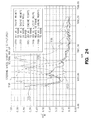
- FIG. 24 the effect of damping member 920 while gear selector unit 726 is in a neutral setting is shown.
- the rpm of diesel engine 702 is shown on the x-axis and the amount of vibration experienced at the steering wheel 500, measured in g (acceleration - linear scale), is shown on the y-axis.
- the acceleration at the steering wheel is measured with an accelerometer attached to the steering wheel 500.
- Curve 930 corresponds to a first test vehicle 100 having the engine mounts described herein with a 70 durometer polyurethane connecting portion 864.
- Curve 932 corresponds to the same first test vehicle including a damping member 920 with a 6.6 kilogram damping mass 924 coupled to diesel engine 702.
- Curve 934 corresponds to the same test vehicle having a three mount configuration instead of four (two on the engine, one on the transmission).
- Curve 936 corresponds to the same test vehicle having the engine mounts described herein with a 80 durometer polyurethane connecting portion 864.
- Curve 938 corresponds to a second test vehicle having the setup of the first test vehicle of curve 930.
- FIG. 23 the effect of damping member 920 while gear selector unit 726 is in a high forward gear setting is shown.
- the vehicle was driven on an asphalt test track.
- the rpm of diesel engine 702 is shown on the x-axis and the amount of vibration experienced at the steering wheel 500, measured in g (acceleration - linear scale), is shown on the y-axis.
- Curve 940 corresponds to a first test vehicle 100 having the engine mounts described herein with a 70 durometer polyurethane connecting portion 864.
- Curve 942 corresponds to the same first test vehicle including a damping member 920 with a 6.6 kilogram damping mass 924 coupled to diesel engine 702.
- Curve 944 corresponds to the same test vehicle having a three mount configuration instead of four (two on the engine, one on the transmission).
- Curve 946 corresponds to the same test vehicle having the engine mounts described herein with a 80 durometer polyurethane connecting portion 864.
- Curve 948 corresponds to a second test vehicle having the setup of the first test vehicle of curve 940.
- the muffler 960 of the exhaust system includes an outlet under cargo bed 120 which is forward of rear axle 110.
- vehicle 100 includes four headlights 964.
- headlights 964 are adjustable to direct the light up and down, as well as, left and right.
- VCM vehicle control module
- Vehicle control module 970 is configured to be used with both of a gasoline based engine and diesel based engine 702. Configuration mode is sensed at startup by the vehicle control module 970.
- the vehicle control module 970 may be used to perform the following functions: Glow Plug relay control, Glow Plug Indicator/countdown lamp, Fuel Pull Solenoid control, Cooling fan relay control, AWD coil control, Overtemp lamp control, Alternator Controlled Switch (ACS) relay control, Rear Differential Driver Control w/PWM, Speed Limiter air Solenoid Control w/PWM.
- vehicle control module 970 communicates with or monitors various sensors or modules through dedicated wiring.
- vehicle control module 970 communicates with or monitors various sensors or modules through a network, such as a CAN network.
- the vehicle control module 970 may also store and provide diagnostic information.
- the vehicle control module 970 may interface with an external display and/or computer to assist with troubleshooting and system testing.
- the VCM 970 monitors the Ignition Key or input 972 to determine when it is in an ON state.
- the VCM 970 identifies whether prime mover 700 is a diesel engine or a gasoline engine.
- the VCM 970 utilizes a dual thermistor/identifier to determine whether the prime mover 700 is a diesel engine or a gasoline engine.
- the connector to the VCM 970 has three connection points relative to the thermistor 974.
- a first connection point is ground.
- a second connection point is a constant voltage when associated with a diesel engine and connected to one side of the thermistor 974 with a gasoline engine.
- a third connection point is a constant voltage when associated with a gasoline engine and connected to one side of the thermistor with a diesel engine.
- VCM 970 may determine whether prime mover 700 is a diesel engine or a gasoline engine.
- the thermistor 974 monitors the temperature of the engine coolant for the respective diesel engine or gasoline engine.
- the VCM 970 monitors the engine speed or tach of the respective diesel engine or gasoline engine.
- the tach signal is provided by a hall effect sensor 976 on the starter ring. In one embodiment, the sensor 976 will detect 105 teeth per 1 engine revolution.
- the tach signal is provided from an rpm sensor 978 associated with one of the stator outputs. In one embodiment, the rpm sensor 978 will detect 6 pulses per revolution.
- the VCM 970 monitors a ground speed of the vehicle.
- a Hall effect sensor 980 is provided on the transmission after the CVT.
- Vehicle control module 970 uses the ground speed input to control top speed of a gasoline powered vehicle.
- Vehicle control module 970 uses the ground speed input for all-wheel drive (“AWD") and Turf (ON - only a single ground engaging member receiving power for a given axle; OFF - power is provided to both ground engaging members).
- Vehicle control module 970 may have an internal pull up resistor on the line to work with Open Collector Hall Effect speed sensor.
- the VCM 970 monitors a state of the parking brake of vehicle 100.
- a parking brake sensor 981 is provided to monitor whether the parking brake is set or not.
- the parking brake sensor 981 is normally open and switched to ground when the parking brake is applied.
- Vehicle control module 970 also checks the parking brake sensor 981 when deciding whether to permit turf mode operation or not. When the parking brake sensor 981 is grounded (parking brake applied) turf mode is deactivated so that both of the ground engaging members of rear axle 110 are locked.
- the VCM 970 controls when vehicle 100 may be in a Turf Mode of operation.
- VCM 970 monitors an operator actuated Turf Mode switch 979 in operator area 130. An operator may request Turf Mode by actuating switch 979.
- a Turf Mode When a Turf Mode is active, only a single ground engaging member receiving power for a given axle. When a Turf Mode is inactive all ground engaging members of a given axle are provided power.
- Vehicle control module 970 controls a solid state relay 982 to control a solenoid 983 of rear drive unit 730 to either activate or deactivate Turf Mode operation.
- the solenoid output is powered On (driven Low) continuously for approx 2 seconds and then a PWM signal is used to maintain solenoid engagement, which limits current draw and internal heating of the solenoid.
- turf mode engagement is limited to a ground speed of less than 10 MPH. Additional details regarding controlling one or more of a rear differential and a front differential are provided in US Provisional Patent Application Serial No. 61/187,147 , titled ELECTRIC VEHICLE, filed June 15, 2009, the disclosure of which is expressly incorporated by reference herein. Additional details are provided in US Patents 6,976,553 ; 7,220,209 ; and 7,600,599 , the disclosures of which are expressly incorporated by reference herein.
- Vehicle control module 970 also controls in a diesel powered vehicle an over temperature lamp 984 for the coolant, a cooling fan relay 986 for activating a fan on radiator 604, an AWD coil 988 located in the front differential 734 to control the engagement of the front ground engaging members, a wait to start lamp 990 which provides an indication of when to start engine 702 (allowing the engine to preheat for a given amount of time based on coolant temperature), a glow plug relay 992 which activates the glow plugs of engine 702, and a fuel supply pull solenoid 944 which is energized briefly to allow fuel to be drawn to engine 702 at startup (subsequently a second coil maintains the solenoid in an open position while the vehicle is running).
- the AWD coil driver in the front differential 734 will not turn on the AWD coil if the vehicle is traveling above 8 MPH.
- ground speed input is equal to 0 MPH (possible missing input)
- the engine RPM must be below 1800 RPM before allowing engagement of all wheel drive.
- An AWD switch may be provided in the operator space to provide control to the operator to complete or disconnect the supply or return path from the AWD coil (or AWD relay) which then allows the AWD circuit to be active or inactive based on the input state of the AWD switch and the vehicle operating conditions, such as ground speed and engine RPM.
- An SCR or other latching type device is used to keep the AWD circuit engaged by the VCM once it has been engaged until the operator breaks and resets the circuit by turning" Off' the AWD switch on the dash.
- a "Neutral" relay is included which is activated every time the gear selector unit 726 is passed through the neutral position.
- the relay's normally closed contacts are wired in series with the AWD coil. This allows the AWD circuit to be broken (opened) each time the vehicle's direction is changed from forward to reverse and allows the front differential to "unlock” during the direction change. This feature is useful for preventing front driveline "wedging” which can occur when the differential remains locked and a rotational direction change is made.
- Vehicle control module 970 in a gas vehicle controls an over temperature lamp 984, a cooling fan relay 986, an Alternator Controlled Switch (ACS) relay 996 which powers the hour meter, the fuel pump, and a speed limiter solenoid 998 which limits the air entering a carburetor of the gasoline engine.
- ACS Alternator Controlled Switch
- An exemplary speed limiter system is disclosed in US Patent Application Serial No. 12/501,944 , titled VEHICLE HAVING A CONTROL UNIT, the disclosure of which is expressly incorporated by reference herein.
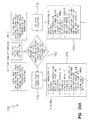
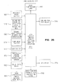
- FIGS. 33A and 33B An exemplary processing sequence 1100 of vehicle control module 970 is provided in FIGS. 33A and 33B . As shown in FIG. 33A , the vehicle control module 970 at ignition on determines the type of vehicle and then undertakes the appropriate sequence, as represented by blocks 1102-1106.
- VCM 970 performs several operations at ignition “on” (power applied to VCM module 970).
- the Thermistor resistance/temperature is checked against a lookup table to determine the appropriate glow plug "pre-start” and "post start” times.
- the Glow plug relay is closed, the Glow plug/Wait to start lamp in the operator area 130 would illuminate if required based on coolant temperature, the fuel solenoid pull relay is closed, the cooling fan is turned on if needed, an AWD input in the operator area 130 and the turf mode switch 979 are checked and the appropriate modes implemented if allowed, and a countdown from the "pre-start" time begins.
- the fuel solenoid pull relay releases, as represented by block 1110, but it is held open by the hold solenoid which remains active until ignition off.
- the Glow Plug/Wait to start lamp turns off, as represented by block 1112.
- the glow plug relay continues to remain on for the "post-start” time, as represented by block 1112.
- VCM 970 continues to check if cooling fan operation is required, and the allowability of the AWD and Turf Modes, if requested, as represented by block 1114.
- VCM 970 performs several operations at ignition “on” (power applied to VCM module 970). As represented in block 1120, the Thermistor resistance/temperature is checked, an over temperature lamp in the operator area 130 is turned on for a 1 second test lamp (as noted in block 1122), the cooling fan is turned on if needed, the turf mode switch 979 are checked and the appropriate modes implemented if allowed, and the ACS relay 996 is turned on for 3 seconds and then turned off until an engine rpm signal is detected. During operation of vehicle 100, VCM 970 continues to check if cooling fan operation is required, the allowability of the Turf Mode, if requested, and the whether the ground speed limiter solenoid should be operated, as represented by block 1124.
- one or more modules of vehicle 100 are a part of a network system which permits the inclusion of expansion modules for accessories or vehicle upgrades.
- Exemplary vehicle components and controls associated with an exemplary CAN network are disclosed in US Patent Application 11/218,163, filed September 1, 2005 , titled CONTROLLER AREA NETWORK BASED SELF-CONFIGURING VEHICLE MANAGEMENT SYSTEM AND METHOD, US Patent Application 12/475,531, filed May 31, 2008 , titled VEHICLE SECURITY SYSTEM, and US Provisional Patent Application Serial No. 61/187,147 , titled ELECTRIC VEHICLE, filed June 15, 2009, the disclosures of which are expressly incorporated by reference herein.
- VCM 970 and other electrical components may be cooled by thermally coupling them to the airflow generated by or for CVT 714 or prime mover 700.
- Other electrical components include a voltage regulator and other electronic devices.
- Air conduit 1000 guides or otherwise directs air 1002 from a first location 1004 towards a second location 1006.
- air 1002 is pushed from first location 1004 towards second location 1006.
- a blower or other device pushes air 1002 from first location 1004 towards second location 1006.
- air 1002 is drawn from first location 1004 towards second location 1006.
- a CVT 714 or an internal combustion engine, such as diesel engine 702 draws air 1002 from first location 1004 towards second location 1006.
- a voltage regulator 1010 is shown in FIG. 36 adjacent to the wall 1008 of air conduit 1000.
- voltage regulator 1010 is coupled to air conduit 1000 and air conduit 1000 holds voltage regulator 1010 in place.
- voltage regulator 1010 is coupled to air conduit 1000 and voltage regulator 1010 is held by frame 150 independent of air conduit 1000. Fins 1012 or other heat transfer features of voltage regulator 1010 extend into air conduit 1000 and contact air 1002 traveling through air conduit 1000. The air removes heat from voltage regulator 1010 and cools the electrical devices of voltage regulator 1010.
- voltage regulator 1010 may be placed at various locations of an air intake system for diesel engine 702 or a gasoline engine.
- Voltage regulator 1010 may be placed in a first location 1020 of fluid conduit 642 such that fins 1012 are exposed to air passing from air intake housing 640 to airbox 644.
- First location 1020 is located forward of operator area 130.
- Voltage regulator 1010 may be placed in a second location 1022 of fluid conduit 642 such that fins 1012 are exposed to air passing from air intake housing 640 to airbox 644.
- Second location 1022 is located rearward of steering wheel 500.
- Voltage regulator 1010 may be placed in a third location 1024 of fluid conduit 646 such that fins 1012 are exposed to air passing from airbox 644 to diesel engine 702.
- the air 1002 is drawn through fluid conduit 642 and fluid conduit 646 due to the intake suction of diesel engine 702.
- Fins 1012 of voltage regulator 1010 may be placed anywhere along the length of fluid conduit 642 or fluid conduit 646, within air intake housing 640, or within airbox 644 so long as air is moved over fins 1012 of voltage regulator 1010 to cool fins 1012.
- Voltage regulator 1010 may be placed at various locations of an air intake system for CVT 714. Voltage regulator 1010 may be placed in a fourth location 1026 of fluid conduit 485 such that fins 1012 are exposed to air passing from air intake housing 484 to CVT housing 722. The air is drawn through fluid conduit 485 due to the draw of the spinning drive clutch member 712 and driven clutch member 718. Fins 1012 of voltage regulator 1010 may be placed anywhere along the length of fluid conduit 485, within air intake 484, or within CVT housing 722 so long as air is moved over fins 1012 of voltage regulator 1010. Depending on the temperature of the exhaust of CVT 714, voltage regulator 1010 may be placed at various locations of the air exhaust system for CVT 714.
- Voltage regulator 1010 may be placed in a fifth location 1030 of air exhaust 650 such that fins 1012 are exposed to air being forced out of CVT housing 722. Fins 1012 of voltage regulator 1010 may be placed anywhere along the length of air exhaust 650 or proximate an output of air exhaust 650 so long as air is moved over fins 1012 of voltage regulator 1010.
- air conduit 1000 may have many different shapes.
- air conduit 1000 is a generally cylindrically shaped member, such as portions fluid conduit 642.
- air conduit 1000 may be formed by a hood and other body members, such as with a snowmobile.
- the fins 1012 are mounted protruding through a fan guard of a snowmobile to expose voltage regulator 1010 to the air generated by the CVT 714 of the snowmobile.
- the air conduit 1000 is a part of an engine cooling system for an air cooled engine.
Landscapes
- Engineering & Computer Science (AREA)
- Chemical & Material Sciences (AREA)
- Combustion & Propulsion (AREA)
- Transportation (AREA)
- Mechanical Engineering (AREA)
- Arrangement Of Transmissions (AREA)
- Arrangement Or Mounting Of Propulsion Units For Vehicles (AREA)
- Body Structure For Vehicles (AREA)
Description
- The present invention relates to vehicles having side-by-side seating and in particular to vehicles having side-by-side seating.
- A continously variable transmission unit having an input shaft and an output shaft, the input shaft coupled to an engine, is described in
WO2008/005131 - Present invention provides a vehicle as defined by the features of
claim 1. - In an exemplary embodiment of the present disclosure, a vehicle is provided. The vehicle comprising a plurality of ground engaging members; a frame supported by the plurality of ground engaging members; an operator area supported by the frame, the operator area including driver controls and seating adapted to support at least one person. The vehicle is also provided with a prime mover, and a transmission having a CVT. The transmission is operatively coupled to the prime mover and at least one of the plurality of ground engaging members to propel the vehicle. The prime mover and transmission are in the form of an assembly supported by the frame. The vehicle further comprising a plurality of mounts coupled to the frame and supporting the assembly to isolate the assembly relative to the frame.
- In one example, the plurality of mounts permit a movement of the assembly relative to the frame in a direction normal to a vertical plane passing through a vehicle centerline of the vehicle. In another example, at least a first mount is directly coupled to the prime mover and directly coupled to the frame and at least a second mount is directly coupled to the transmission and directly coupled to the frame, the second mount being spaced apart from the first mount.
- In yet another example, at least a first mount and a second mount are directly coupled to the prime mover and at least a third mount and a fourth mount are directly coupled to the transmission, a lower portion of the first mount and the second mount being in a first plane and a lower portion of the third mount and the fourth mount being in a second plane, the second plane being offset from the first plane.
- In a further example, the vehicle further comprises a rear drive unit positioned rearward of the operator area and coupled to a first ground engaging member and a second ground engaging member both positioned rearward of the operator area; a rear drive shaft operatively coupling the rear drive and the CVT, the CVT providing power to the rear drive; wherein at least a third mount and a fourth mount are directly coupled to the transmission and are coupled to the frame at respective positions outboard of the rear drive shaft.
- In a variation thereof, the vehicle further comprises a front drive unit positioned forward of the operator area and coupled to a third ground engaging member and a fourth ground engaging member both positioned forward of the operator area; and a front drive shaft operatively coupling the front drive and the CVT, the CVT providing power to the front drive, wherein at least a first mount and a second mount are directly coupled to the prime mover and are coupled to the frame at respective positions outboard of the front drive shaft.
- In still a further example, the vehicle further comprises a damping member coupled to the assembly, the damping member being tuned to reduce the transfer of vibration from the assembly to the frame.
- In another exemplary embodiment of the present disclosure, a vehicle is provided. The vehicle comprises a plurality of ground engaging members; a frame supported by the plurality of ground engaging members; an operator area supported by the frame, the operator area including driver controls and seating adapted to support at least one person; an engine supported by the frame; a gearbox having an input shaft and an output shaft, the input shaft being coupled to the engine to receive power from the engine; and a CVT unit having a drive clutch member coupled to the output shaft of the gearbox and a driven clutch member coupled to the drive clutch member, the driven clutch member being operatively coupled to at least one of the plurality of ground engaging members to propel the vehicle. The rotation ratio of the output shaft of the gearbox to the input shaft of the gearbox being greater than 1.
- In one example, the rotation ratio of the output shaft of the gearbox to the input shaft of the gearbox is about 2.1.
- In another example, a speed of the input shaft of the gearbox is in the range of about 3000 rpm to about 3600 rpm and a speed of the output shaft of the gearbox has a corresponding range of about 7200 rpm to about 8000 rpm.
- In a further example, the vehicle further comprises a rear drive unit positioned rearward of the operator area and coupled to a first ground engaging member and a second ground engaging member both positioned rearward of the operator area; a rear drive shaft operatively coupling the rear drive and the CVT, the CVT providing power to the rear drive; a front drive unit positioned forward of the operator area and coupled to a third ground engaging member and a fourth ground engaging member both positioned forward of the operator area; and a front drive shaft operatively coupling the front drive and the CVT, the CVT providing power to the front drive.
- In still a further example, the vehicle further comprises a coupling member positioned between the engine and the gearbox, the coupling member transferring power from the engine to the gearbox.
- In a further exemplary embodiment of the present disclosure, a vehicle is provided. The vehicle comprising a plurality of ground engaging members; a frame supported by the plurality of ground engaging members; an operator area supported by the frame, the operator area including driver controls and seating adapted to support at least one person; an engine supported by the frame being operatively coupled to at least one of the plurality of ground engaging members to propel the vehicle. The vehicle further comprising an alternator supported by the frame; an output pulley coupled to and rotatable by the engine; and an input pulley coupled to the alternator and coupled to the output pulley. The alternator provides at least about 50% charging capacity when the engine is at idle and about 100% charging capacity when engine is operating at about 50% engine capacity.
- In one example, the vehicle further comprising a rear drive unit positioned rearward of the operator area and coupled to a first ground engaging member and a second ground engaging member both positioned rearward of the operator area; a rear drive shaft operatively coupling the rear drive and the CVT, the CVT providing power to the rear drive; a front drive unit positioned forward of the operator area and coupled to a third ground engaging member and a fourth ground engaging member both positioned forward of the operator area; and a front drive shaft operatively coupling the front drive and the CVT, the CVT providing power to the front drive.
- The above-mentioned and other features and advantages of this disclosure, and the manner of attaining them, will become more apparent and the invention itself will be better understood by reference to the following description of embodiments of the invention taken in conjunction with the accompanying drawings, wherein:
-
FIG. 1 illustrates a perspective view of an exemplary utility vehicle; -
FIG. 2 illustrates a left side view of the exemplary utility vehicle ofFIG. 1 ; -
FIG. 3 illustrates a right side view of the exemplary utility vehicle ofFIG. 1 ; -
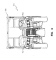
FIG. 4 illustrates a front view of the exemplary utility vehicle ofFIG. 1 ; -
FIG. 5 illustrates a rear view of the exemplary utility vehicle ofFIG. 1 ; -
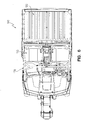
FIG. 6 illustrates a top view of the exemplary utility vehicle ofFIG. 1 ; -
FIG. 7 illustrates a bottom view of the exemplary utility vehicle ofFIG. 1 ; -
FIG. 8 illustrates a perspective view of a chassis of the exemplary utility vehicle; -
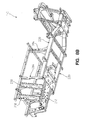
FIG. 8A illustrates an upper, perspective view of a frame of the chassis ofFIG. 8 ; -
FIG. 8B illustrates a lower, perspective view of the frame of the chassis ofFIG. 8 ; -
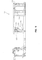
FIG. 9 illustrates a left side view of the frame of the chassis ofFIG. 8 ; -
FIG. 10 illustrates a right side view of the frame of the chassis ofFIG. 8 ; -
FIG. 11 illustrates a front view of the frame of the chassis ofFIG. 8 ; -
FIG. 12 illustrates a rear view of the frame of the chassis ofFIG. 8 ; -
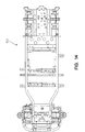
FIG. 13 illustrates a top view of the frame of the chassis ofFIG. 8 ; -
FIG. 14 illustrates a bottom view of the frame of the chassis ofFIG. 8 ; -
FIG. 15 illustrates a representative view of an drivetrain system; -
FIG. 16 illustrates a plurality of mounts for the engine and transmission of the drivetrain ofFIG. 15 ; -
FIG. 17 illustrates a first lower perspective view of the engine and transmission of the drivetrain ofFIG. 15 including the mounts ofFIG. 16 ; -
FIG. 18 illustrates a second lower perspective view of the engine and transmission of the drivetrain ofFIG. 15 including the mounts ofFIG. 16 ; -
FIG. 19 illustrates a portion of one of the mounts ofFIG. 16 ; -
FIG. 20 illustrates an exemplary drivetrain system; -
FIG. 21 illustrates a damping member mounted to the engine of the drivetrain system ofFIG. 20 ; -
FIG. 22 illustrates a lower perspective view of the damping member ofFIG. 21 ; -
FIG. 23 illustrates the effect of the damping member ofFIGS. 21 and22 on vibration when the vehicle is running in a high gear; -
FIG. 24 illustrates the effect of the damping member ofFIGS. 21 and22 on vibration when the vehicle is running in a neutral setting; -
FIG. 25 illustrates the connection between a engine and a transmission of the drivetrain system ofFIG. 20 -
FIG. 26 illustrates a top view of the drivetrain system ofFIG. 20 ; -
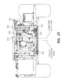
FIG. 27 is a front view through the operator area ofFIG. 1 with the seating, roll cage, and body work removed; -
FIG. 28 illustrates a top view of the exemplary vehicle ofFIG. 1 with the body panels, cargo bed, and roll cage removed; -
FIG. 29 illustrates a cooling hose restraint; -
FIG. 30 illustrates the location of a throttle control cable bracket and a gear selector cable bracket; -
FIGS. 31 and32 illustrate the air input and exhaust systems for the engine and the CVT of the vehicle; -
FIGS. 33A and33B illustrate a flow chart of a processing sequence executed by a controller of the vehicle; -
FIG. 34 illustrates a vehicle control module related to a diesel mode of operation; -
FIG. 35 illustrates a vehicle control module related to a diesel mode of operation; and -
FIG. 36 illustrates an electrical component being thermally coupled to the air passing through an air conduit. - Corresponding reference characters indicate corresponding parts throughout the several views. Unless stated otherwise the drawings are proportional.
- The embodiments disclosed below are not intended to be exhaustive or to limit the invention to the precise forms disclosed in the following detailed description. Rather, the embodiments are chosen and described so that others skilled in the art may utilize their teachings. While the present disclosure is primarily directed to a utility vehicle, it should be understood that the features disclosed herein may have application to other types of vehicles such as all-terrain vehicles, motorcycles, watercraft, snowmobiles, and golf carts. Further, although described in the context of a diesel powered vehicle, the embodiments disclosed herein may be implemented as part of a hybrid vehicle, a gasoline powered vehicle, any other suitable type of internal combustion powered vehicle, or an electric vehicle.
- Referring to
FIG. 1 , an illustrative embodiment of avehicle 100 is shown.Vehicle 100 as illustrated includes a plurality ofground engaging members 102. Illustratively,ground engaging members 102 arewheels 104 and associatedtires 106. Other exemplary ground engaging members include skis and tracks. In one embodiment, one or more of the wheels may be replaced with tracks, such as the Prospector II Tracks available from Polaris Industries, Inc. located at 2100 Highway 55 in Medina, MN 55340. - In addition to vehicle 100, the teachings of the present disclosure may be used in combination with the suspension systems, drive configurations, modular subsections, power steering units, and other features described in any one of
US Provisional Patent Application Serial No.: 60/918,502 US Provisional Patent Application Serial No.: 60/918,556 US Provisional Patent Application Serial No.: 60/918,444 US Provisional Patent Application Serial No.: 60/918,356 US Provisional Patent Application Serial No.: 60/918,500 US Utility Patent Application Serial No.: 12/050,048 , titled VEHICLE WITH SPACE UTILIZATION, filed March 17, 2008;US Utility Patent Application Serial No.: 12/050,064 , titled VEHICLE WITH SPACE UTILIZATION, filed March 17, 2008;US Utility Patent Application Serial No.. 12/050,041 , titled METHOD AND APPARATUS RELATED TO TRANSPORTABILITY OF A VEHICLE filed March 17, 2008;US Utility Patent Application Serial No.: 12/092,151 US Utility Patent Application Serial No.: 12/092,153 US Utility Patent Application Serial No.: 12/092,191 US Utility Patent Application Serial No.: 12/135,107 US Utility Patent Application Serial No.: 12/134,909 US Utility Patent Application Serial No.: 12/218,572 US Utility Patent Application Serial No.: 12/317,298 US Utility Patent Application Serial No.: 12/484,921 US Provisional Patent Application Serial No. 61/187,147 - Referring to the illustrated embodiment in
FIG. 1 , a first set of wheels, one on each side ofvehicle 100, generally correspond to afront axle 108. A second set of wheels, one on each side ofvehicle 100, generally correspond to arear axle 110. Although each offront axle 108 andrear axle 110 are shown having a singleground engaging members 102 on each side, multipleground engaging members 102 may be included on each side of the respectivefront axle 108 andrear axle 110. As configured inFIG. 1 ,vehicle 100 is a four wheel, two axle vehicle. As mentioned herein one or more ofground engaging members 102 are operatively coupled to a drivetrain 112 (seeFIG. 20 ) to power the movement ofvehicle 100. - Returning to
FIG. 1 ,vehicle 100 includes abed 120 having acargo carrying surface 122.Cargo carrying surface 122 may be flat, contoured, and/or comprised of several sections.Bed 120 further includes a plurality of mounts 124 (one indicated) for receiving an expansion retainer (not shown) which may couple various accessories tobed 120. Additional details of such mounts and expansion retainers are provided inUS Patent No. 7,055,454, to Whiting et al., filed July 13, 2004 , titled "Vehicle Expansion Retainers," the disclosure of which is expressly incorporated by reference herein. -
Vehicle 100 includes anoperator area 130 including seating 132 for one or more passengers.Operator area 130 further includes a plurality of operator controls 134 by which an operator may provide input into the control ofvehicle 100. Controls 134 may include controls for steering, shifting gears, acceleration, and braking. Seating 132 includes aseat bottom portion 136 and a seat backportion 138 and head rests (not shown). Seating 132 is shown as bucket seats 140 and 142 with a console portion 144 therebetween. As shown herein, theoperator area 130 only includes side-by-side seating for individuals in a first row. In one embodiment, operator area is configured such that seating 132 includes multiple rows of side-by-side seating. -
Vehicle 100 includes four wheel independent suspensions. Referring toFIG. 28 , each ofground engaging members 102 ofrear axle 110 is coupled to frame 150 (FIG. 8A ) through arear suspension 152. In one embodiment, each of the ground engaging members of the rear axle are coupled to a rear drive unit through a half shaft. Each ofground engaging members 102 offront axle 108 is coupled to frame 150 through a front suspension 160. In one embodiment, each of the ground engaging members of the rear axle are coupled to a rear drive unit through a half shaft. In one embodiment, therear drive unit 730 is offset from the vehicle centerline and the half shafts to the rear ground engaging members are of unequal length. - In addition to the
bed 120, utility vehicle includes a plurality of body components, and as best shown inFIGS. 1-6 , namelyside panels 170,floor boards 172,wheel wells 174, dash 176,rollover structure 178,hood 180, andbumper 182. All of these items are directly or indirectly attached to and/or supported by the vehicle frame 150 (seeFIG. 8 ). - With reference to
FIGS. 8-14 ,frame 150 supportsrollover structure 178.Frame 150 includes afront frame portion 210, arear frame portion 212 and anintermediate frame portion 214. Theframe portions drivetrain 112. Thewheels 104 offront axle 108 are coupled tofront frame portion 210 offrame 150 and supportfront frame portion 210 offrame 150 above the ground.Intermediate frame portion 214 includes aseat support portion 216. Thewheels 104 ofrear axle 110 are coupled torear frame portion 212 offrame 150 and supportrear frame portion 212 offrame 150 above the ground.Rear frame portion 212 offrame 150 further includes abed support portion 218. - With respect to
FIG. 8A ,frame 150 will be described.Frame 150 includes longitudinally extendingframe members 220 which extend a substantial length of the vehicle and neck down to form front frame members at 222.Support plates 224 and 226 span theframe members 222.Rear frame portion 212 is defined bychannel members 230 extending from atransverse portion 232. -
Intermediate frame portion 214 is comprised oftransverse channels 240 extending between longitudinally extendingframe members 220 andtransverse channel portions frame members 220. Frame tube 262 (seeFIG. 8 ) is positioned at the end oftransverse channel portions 242 and frame tube 264 is positioned at the end oftransverse channel portions 244. - With respect again to
FIG. 8 andFIG. 22 ,seat support platform 216 is supported byupper frame members 270 which are elevated from the longitudinal extendingsupport members 220 by way ofvertical support members 284. - Referring to
FIG. 15 , anexemplary drivetrain system 112 is represented. Aprime mover 700 is shown. In the illustrated embodiment,prime mover 700 is adiesel engine 702. Other exemplary prime movers include gasoline engines, other suitable internal combustion engines, an electric motor, a hybrid system including both an internal combustion engine and an electric motor, a fuel cell, and any other suitable device for providing a source of power. - In one embodiment,
diesel engine 702 is a liquid cooled engine. Referring toFIG. 28 ,coolant lines radiator 604 positioned forward offront axle 108.Coolant lines frame 150. Referring toFIG. 29 , underneathseating 130, thecoolant lines engine 702. Retainingmember 606 is provided to generally maintaincoolant lines frame 150, such asportion 608. - An
output shaft 704 ofdiesel engine 702 is operatively coupled to a gearbox 708. In the illustrated embodiment, the gearbox 708 is positioned within ahousing 706 of a shiftable transmission. Gearbox 708 has anoutput shaft 710 which is operatively coupled to adrive clutch 712 of a continuously variable transmission ("CVT") 714. In one embodiment, gearbox 708 is configured so thatoutput shaft 710 rotates at a higher number of revolutions per minute ("rpm") thanoutput shaft 704. In one embodiment, gearbox 708 is configured so thatoutput shaft 710 rotates at a lower number of revolutions per minute thanoutput shaft 704. In one embodiment, the ratio of revolutions per minute ofoutput shaft 710 tooutput shaft 704 is 1.15 to 1. In one example, this results invehicle 100 having a top speed of about 30 miles per hour whenoutput shaft 704 is revolving at about 3000 rpm. Of course, the speed ofvehicle 100 may be influenced by many other factors including the tuning ofCVT 714, the gearing ofgear selector unit 726, and the gearing of the front andrear drive units - In one embodiment, the ratio of revolutions per minute of
output shaft 710 tooutput shaft 704 is about 2.1 to 1. In one example, this results invehicle 100 having a top speed of about 50 miles per hour whenoutput shaft 704 is revolving at about 3000 rpm. An exemplary arrangement for altering the rpm ofoutput shaft 710 is shown inUS Patent Application Serial No. 12/069,521 , the disclosure of which is expressly incorporated by reference herein, wherein the rpm of an output shaft which connects to a drive clutch of a CVT is altered from the rpm of an input shaft connected to an engine through a set of gears. The gearbox 708 includes a plurality of gears which causeoutput shaft 710 to rotate at a rate greater than the rotation rate of theinput shaft 898 of gearbox 708. In one embodiment,diesel engine 702 is governed at about 3000 to about 3600 rpm and gearbox 708 is configured to drive clutch 712 at about 7200 to about 8000 rpm. - Drive clutch 712 is coupled to a driven clutch 718 through a
belt 720. Thedrive clutch 712, drivenclutch 718, andbelt 720 are housed in aCVT housing 722. In one embodiment, drive clutch 712 and driven clutch 718 correspond to the drive clutch and driven clutch disclosed inUS Patent Application Serial No. 12/069,521 , the disclosure of which is expressly incorporated by reference herein. One or both ofdrive clutch 712 and driven clutch 718 includes impellers which direct airflow withinCVT housing 722 to cool atleast belt 720. Additional details of continuously variable transmissions are provided inU.S. Pat. No. 6,149,540 andU.S. Pat. No. 7,163,477 , the disclosures of which are expressly incorporated by reference herein. - In one embodiment,
CVT housing 722 is a sealed housing.CVT housing 722 seals against theshiftable transmission housing 706 to seal an interior ofCVT housing 722. By including the gearbox 708 andgear selector unit 726 in a common housing, or otherwise in a fixed relationship, a distance between the input of the gear selector unit and the output shaft of the gearbox may be maintained, even if the assembly ofdiesel engine 702 andtransmission housing 706 is vibrating. This in turn maintains the spacing of the rotation axis of the driveclutch member 712 ofCVT 714 and the drivenclutch member 718 ofCVT 714. In the illustrated embodiment,transmission housing 706 is positioned rearward ofdiesel engine 702 andCVT 714 is positioned rearward oftransmission housing 706. - Driven clutch 718 is operatively coupled to an
output shaft 724 which is coupled to agear selector unit 726.Gear selector unit 726 includes gearing which is coupled to afirst output shaft 728 which is operatively coupled to arear drive unit 730 and asecond output shaft 732 which is operatively coupled to afront drive unit 734. The gearing ofgear selector unit 726 permits the selection of at least one forward gear which causesvehicle 100 to be propelled indirection 740 and at least one reverse gear which causesvehicle 100 to be propelled indirection 742. In one embodiment, at least two forward gears are provided (low and high), a first reverse gear, and a neutral position. Although,gear selector unit 726 is represented as having bothfirst output shaft 728 andsecond output shaft 732, in one embodiment,gear selector unit 726 only includes one offirst output shaft 728 andsecond output shaft 732 and the correspondingrear drive unit 730 andfront drive unit 734 is removed. -
Front drive unit 734 has twooutput shafts front drive unit 734 to one ofground engaging member 102 offront axle 108.Output shafts ground engaging member 102 with the power generated bydiesel engine 702. In one embodiment,front drive unit 734 is a lockable differential which may be locked to provide power to both ofoutput shafts output shafts output shafts US Provisional Patent Application Serial No. 61/187,147 - In one embodiment,
front drive unit 734 is an automatic locking front differential manufactured by Hilliard Corporation of Elmira, NY, and has an overrunning clutch. Exemplary overrunning clutches are disclosed inU.S. Patent RE38,012E , the subject matter of which is incorporated herein by reference. In one embodiment,front drive unit 734 operates under the principle described inU.S. Patent 5,036,939 , the subject matter of which is incorporated herein by reference. In one embodiment,front drive unit 734 is designed to engage when the wheel slippage is in the range of 10-30%. In one embodiment,front drive unit 734 is a Model No. 1332670 available from Polaris Industries Inc. of Medina Minnesota. In one embodiment,front drive unit 734 which includes active descent control and is available from Polaris Industries Inc. of Medina Minnesota. -
Rear drive unit 730 has twooutput shafts rear drive unit 730 to one ofground engaging member 102 ofrear axle 110.Output shafts ground engaging member 102 with the power generated bydiesel engine 702. In one embodiment,rear drive unit 730 is a lockable differential which may be locked to provide power to both ofoutput shafts output shafts output shafts - Referring to
FIG. 20 , an exemplary representation ofdrivetrain 112 is shown. InFIG. 20 ,diesel engine 702,shiftable transmission housing 706,CVT housing 722,rear drive unit 730, andfront drive unit 734 are shown in the positions they occupy when supported byframe 150.Second output shaft 732 ofgear selector unit 726 is coupled to aninput shaft 748 offront drive unit 734 through aprop shaft 760.Prop shaft 760 includes afirst portion 762 coupled tosecond output shaft 732, asecond portion 764 coupled toinput shaft 748, and athird portion 766 coupled tofirst portion 762 andsecond portion 764 throughuniversal joint 768 anduniversal joint 770, respectively. As shown inFIG. 20 ,prop shaft 760 generally tilts downward as it runs fromsecond output shaft 732 towardsfront drive unit 734. In a similar fashion,first output shaft 728 ofgear selector unit 726 is coupled to aninput shaft 758 ofrear drive unit 730 through aprop shaft 780.Prop shaft 780 includes afirst portion 782 coupled tofirst output shaft 728, asecond portion 784 coupled toinput shaft 758, and athird portion 786 coupled tofirst portion 782 andsecond portion 784 throughuniversal joint 788 anduniversal joint 790, respectively. As shown inFIG. 20 ,prop shaft portion 784 generally tilts downward as it runs fromfirst output shaft 728 towardsrear drive unit 730. In one embodiment,rear drive unit 730 is angled upwards by about 10 degrees. -
Prop shaft 780 further carries aparking brake 792. Adisc 794 ofparking brake 792 is coupled tosecond portion 784 ofprop shaft 780. A caliper 796 is supported byframe 150 and actuatable by an operator input 798 (seeFIG. 2 ) to either engagedisc 794 or not. - Referring to
FIG. 30 , afirst bracket 620 is coupled todiesel engine 702.Bracket 620 includes arecess 621 which receives a throttle cable which is operatively coupled to theengine 702 and to a throttle input inoperator area 130. Asecond bracket 622 is coupled toframe 150.Bracket 622 also includes a recess which receives a gear selector cable which is operatively coupled to a gear selector input inoperator area 130. The gear selector cable is also operatively coupled to alink 624 which may be actuated to select a respective gear ingear selector unit 726. - Referring to
FIG. 26 ,rear drive unit 730 is positioned offset from thecenterline 776 ofvehicle 100. As such, the lengths of the twooutput shafts distance 772 from a first side ofrear drive unit 730 to a plane of a wheel carrier (where the wheel of the ground engaging member attaches to the carrier) for theground engaging member 102 on the passenger side ofvehicle 100 is about 533.5 millimeters while adistance 774 from a second side ofrear drive unit 730 to a plane of a wheel carrier (where the wheel of the ground engaging member attaches to the carrier) for theground engaging member 102 on the driver side ofvehicle 100 is about 570.6 millimeters. In one embodiment, adistance 773 from a first side ofrear drive unit 730 to plane 776 is about 120.4 millimeters while adistance 775 from a second side ofrear drive unit 730 to plane 776 is about 82.3 millimeters.Rear drive unit 730 is mounted to plate 800 which is coupled toframe 150. - As shown in
FIG. 26 andFIG. 27 , a vertical plane including thecrankshaft axis 778 is offset from a vertical plane including thevehicle centerline 776. In one embodiment, the offset is about 2 inches (5.08mm).Diesel engine 702 is offset to provide space forprop shaft 760 to pass bydiesel engine 702. - Returning to
FIG. 28 , anair intake housing 640 is shown in a forward portion ofvehicle 100. Theair intake housing 640 includes a filter which filters incoming air. Theair intake housing 640 is in fluid communication with afluid conduit 642 which travels on top of the skid plate back to thediesel engine 702. Referring toFIGS. 31 and32 , thefluid conduit 642 is in fluid communication with anairbox 644. In one embodiment,airbox 644 includes a filter unit to further filter the air. Air enters airbox 644 fromfluid conduit 642 and exits theairbox 644 through afluid conduit 646. By placing the air intake housing up in a front portion ofvehicle 100, the amount of dust and other debris that is introduced into the air intake system is reduced. - Another
air intake 484 is shown inFIGS. 31 and32 .Air intake 484 is for a CVT ofdrivetrain 112.Air intake 484 is positioned between the seats ofseating 130 and is in fluid communication with afluid conduit 485 which is in fluid communication with an interior ofCVT housing 722. Additional details regarding theair intake 484 are provided inUS Patent Application Serial No. 12/135,107, filed June 6, 2008 air exhaust 650 forCVT housing 722 is shown inFIG. 32 . - Referring to
FIG. 27 ,pulley 810 is coupled to the crankshaft ofdiesel engine 702.Pulley 810 is coupled to apulley 812 ofalternator 814 through abelt 816. The rotation ofpulley 810 causesbelt 816 to move andpulley 812 to rotate. Abelt guard 818 is coupled to frame 150 and extends overbelt 816 under seating 132. The ratio ofpulley 810 topulley 812 is selected to increase the charging capacity ofalternator 814. In one embodiment,pulley 812 provides at least about 60% charging capacity whendiesel engine 702 is at idle and 100% whendiesel engine 702 is operating at about 50% engine capacity. In one embodiment,pulley 812 provides at least about 70% charging capacity whendiesel engine 702 is at idle and 100% whendiesel engine 702 is operating at about 50% engine capacity. In one embodiment,alternator 814 provides about 50% percent of its charging capacity whendiesel engine 702 is at idle and about 100% charging capacity whendiesel engine 702 is operating at about 50% engine capacity. In one embodiment,alternator 814 provides about 34 amperes whendiesel engine 702 is at idle and about 55 amperes whendiesel engine 702 is operating at about 50% engine capacity. In the illustrated embodiment, the ratio ofpulley 810 topulley 812 is about 2.31 to 1. An exemplary alternator is the Denso 55A alternator. - Referring to
FIG. 9 ,alternator 814 is positioned inlocation 820. In order to accommodatealternator 814 inlocation 820, thevertical support members 284 on the driver side offrame 150 includes alower portion 822 and anupper portion 824 offset rearward oflower portion 822. The middle section is stiffened with a stiffeningmember 826. - Referring to
FIGS. 17 and18 ,diesel engine 702,shiftable transmission housing 706, andCVT housing 722 are supported by four engine mounts:front mount 830,front mount 832,rear mount 834, andrear mount 836. Each offront mount 830,front mount 832,rear mount 834, andrear mount 836 have a corresponding lower portion (lower portion 840,lower portion 842,lower portion 844, and lower portion 846 ) coupled to frame 150 and a corresponding upper portion (upper portion 850,upper portion 852,upper portion 854, and upper portion 856).Upper portion 850 andupper portion 852 are coupled directly todiesel engine 702.Upper portion 854 andupper portion 856 are coupled directly toshiftable transmission housing 706.Diesel engine 702 andshiftable transmission housing 706 are in turn coupled together at location 848 (seeFIG. 17 ). - Each of
lower portion 840,lower portion 842,lower portion 844, andlower portion 846 are coupled to the corresponding one ofupper portion 850,upper portion 852,upper portion 854, andupper portion 856 through acoupling member 858. Referring toFIG. 19 ,coupling member 858 includes afirst base portion 860, asecond base portion 862, and a connectingportion 864.First base portion 860 is coupled to the respective lower portion 840-846 with fasteners that are received throughapertures 866.Second base portion 862 is coupled to the respective upper portion 850-856 with a fastener that is received throughopening 868. Connectingportion 864 couplesfirst base portion 860 tosecond base portion 862. Connectingportion 864 is an elastomer or other type of material which permitssecond base portion 862 to move relative tofirst base portion 860 generally along its axis indirection 870 anddirection 872, but to generally maintain the position ofsecond base portion 862 relative tofirst base portion 860 in radial directions.Directions vehicle centerline 776. In one embodiment, the durometer of connectingportion 864 is about 70. In one embodiment, the durometer of connectingportion 864 is selected such that the assembly ofdiesel engine 702,shiftable transmission housing 706, andCVT housing 722 may move about 0.5 inches (1.27mm) side-to-side indirection 870 or direction 872 (seeFIG. 13 ). - Referring to
FIGS. 18 and20 , mounts 834 and 836 are positioned lower thanmounts - In one embodiment, instead of four mounts 830-836, only three mounts are provided to support the assembly of
diesel engine 702,shiftable transmission housing 706, andCVT housing 722. In one embodiment,front mount 830 andfront mount 832 are provided as shown inFIG. 17 and a single mount coupled toshiftable transmission housing 706 replacesrear mount 834 andrear mount 836 at alocation 876. - Referring to
FIG. 25 , the connection betweendiesel engine 702 andshiftable transmission housing 706 are shown. Aflange 880 ofdiesel engine 702 mates with aflange 882 of abell housing 884 ofshiftable transmission housing 706 and is secured thereto with a plurality of fasteners (seeFIGS. 17 and18 ). Aflywheel 890 is coupled to the crankshaft ofdiesel engine 702.Flywheel 890 is rotated by the crankshaft. Further,flywheel 890 may be rotated by anelectric starter 892 to initiate the operation ofdiesel engine 702. Attached toflywheel 890 throughfasteners 894 is acoupling member 896. In one embodiment,coupling member 896 is weighted and weighs about 17 kilograms. Couplingmember 896 is weighted to provide additional mass to dampen vibrations fromdiesel engine 702. In one embodiment,diesel engine 702 is a multi-cylinder diesel engine and the weight ofcoupling member 896 balances out the vibration from the diesel engine firing. In one embodiment,diesel engine 702 is a three cylinder diesel engine and the weight ofcoupling member 896 balances out the vibration from the diesel engine firing. - Coupling
member 896 makes the connection between the crankshaft ofdiesel engine 702 and theinput shaft 898 of gearbox 708. Theinput shaft 898 of gearbox 708 is coupled to acoupling member 899. In the illustrated embodiment, a connection is made betweencoupling member 896 ofdiesel engine 702 andcoupling member 899 of gearbox 708 through anintermediate coupler 900.Intermediate coupler 900 includes a plurality ofrecesses 902 on an exterior diameter and a plurality ofrecesses 904 on an interior diameter.Recesses 902 cooperate withfingers 906 ofcoupling member 896 to coupleintermediate coupler 900 tocoupling member 896.Recesses 904 cooperate withfingers 908 ofcoupling member 899 to coupleintermediate coupler 900 tocoupling member 899.Intermediate coupler 900 is illustratively made of a resilient material, such as elastomeric rubber, and provides torsional dampening betweenengine 702 and gearbox 708. Further,intermediate coupler 900 reduces gear noise, reduces torque pulses, reduces impact loading of gear teeth, and reduces clutch wear ofCVT 714. -
Bell housing 884 includes adrain opening 884 in a lower portion ofbell housing 884 and a timing observation slot in an upper portion ofbell housing 884.Bell housing 884 also supports anengine RPM sensor 887. In one embodiment,sensor 887 is a Hall effect sensor. - Referring to
FIGS. 21 and22 , in one embodiment, a dampingmember 920 is mounted todiesel engine 702. Dampingmember 920 includes abracket 922 which carries a dampingmass 924. Dampingmass 924 is placed between tworubber isolators 926.Isolators 926 and dampingmass 924 are supported by a fastener which passes through openings in each and which is coupled tobracket 922.Isolators 926 do permit the movement of dampingmass 924. - The damping
member 920 is coupled to thediesel engine 702 or the shiftable transmission housing. Since the engine/transmission are mounted to theframe 150 through mounts 830-836, the engine transmission vibrate at a resonance frequency. When the engine firing frequency matches this resonance frequency, the engine assembly resonants and the amplified vibration is felt by the rider, such as throughsteering wheel 500. In one embodiment, the resonance frequency is about 32 Hertz. - The damping
member 920 is tuned to resonate at generally the same resonance frequency as the engine/transmission assembly. The dampingmember 920 acts to counteract the vibration of the engine/transmission assembly to reduce the amount of vibration experienced by the operator. In the case of the engine/transmission assembly, the resonance is in the roll direction (rolls, back and forth along the crankshaft axis). In order to increase the effectiveness of dampingmember 920, it is located as far off the crankshaft axis as possible, but still being coupled to the engine/transmission assembly. - In one embodiment, the mass of damping
mass 924 is adjusted until the resonance frequency of dampingmember 920 generally is at the same frequency as the engine/transmission assembly. In one embodiment, dampingmass 924 is a metal --weight which weighs about 6.6 kilograms andisolators 926 are rubber members having a stiffness of about 50 N/millimeter radially and 1400 N/millimeter axially. - Referring to
FIGS. 23 and24 , the effect of the inclusion of dampingmember 920 is shown. Referring toFIG. 24 , the effect of dampingmember 920 whilegear selector unit 726 is in a neutral setting is shown. The rpm ofdiesel engine 702 is shown on the x-axis and the amount of vibration experienced at thesteering wheel 500, measured in g (acceleration - linear scale), is shown on the y-axis. The acceleration at the steering wheel is measured with an accelerometer attached to thesteering wheel 500.Curve 930 corresponds to afirst test vehicle 100 having the engine mounts described herein with a 70 durometerpolyurethane connecting portion 864.Curve 932 corresponds to the same first test vehicle including a dampingmember 920 with a 6.6kilogram damping mass 924 coupled todiesel engine 702.Curve 934 corresponds to the same test vehicle having a three mount configuration instead of four (two on the engine, one on the transmission).Curve 936 corresponds to the same test vehicle having the engine mounts described herein with a 80 durometerpolyurethane connecting portion 864.Curve 938 corresponds to a second test vehicle having the setup of the first test vehicle ofcurve 930. - Referring to
FIG. 23 , the effect of dampingmember 920 whilegear selector unit 726 is in a high forward gear setting is shown. For the curves presented, the vehicle was driven on an asphalt test track. The rpm ofdiesel engine 702 is shown on the x-axis and the amount of vibration experienced at thesteering wheel 500, measured in g (acceleration - linear scale), is shown on the y-axis.Curve 940 corresponds to afirst test vehicle 100 having the engine mounts described herein with a 70 durometerpolyurethane connecting portion 864.Curve 942 corresponds to the same first test vehicle including a dampingmember 920 with a 6.6kilogram damping mass 924 coupled todiesel engine 702.Curve 944 corresponds to the same test vehicle having a three mount configuration instead of four (two on the engine, one on the transmission). Curve 946 corresponds to the same test vehicle having the engine mounts described herein with a 80 durometerpolyurethane connecting portion 864. Curve 948 corresponds to a second test vehicle having the setup of the first test vehicle ofcurve 940. - Referring to
FIG. 2 , themuffler 960 of the exhaust system includes an outlet undercargo bed 120 which is forward ofrear axle 110. Referring toFIG. 3 ,vehicle 100 includes fourheadlights 964. In one embodiment,headlights 964 are adjustable to direct the light up and down, as well as, left and right. - Referring to
FIGS. 34 and35 , a vehicle control module ("VCM") 970 is represented.Vehicle control module 970 is configured to be used with both of a gasoline based engine and diesel basedengine 702. Configuration mode is sensed at startup by thevehicle control module 970. Thevehicle control module 970 may be used to perform the following functions: Glow Plug relay control, Glow Plug Indicator/countdown lamp, Fuel Pull Solenoid control, Cooling fan relay control, AWD coil control, Overtemp lamp control, Alternator Controlled Switch (ACS) relay control, Rear Differential Driver Control w/PWM, Speed Limiter air Solenoid Control w/PWM. In one embodiment,vehicle control module 970 communicates with or monitors various sensors or modules through dedicated wiring. In one embodiment,vehicle control module 970 communicates with or monitors various sensors or modules through a network, such as a CAN network. Thevehicle control module 970 may also store and provide diagnostic information. Thevehicle control module 970 may interface with an external display and/or computer to assist with troubleshooting and system testing. - The
VCM 970 monitors the Ignition Key orinput 972 to determine when it is in an ON state. TheVCM 970 identifies whetherprime mover 700 is a diesel engine or a gasoline engine. In one embodiment, theVCM 970 utilizes a dual thermistor/identifier to determine whether theprime mover 700 is a diesel engine or a gasoline engine. The connector to theVCM 970 has three connection points relative to thethermistor 974. A first connection point is ground. A second connection point is a constant voltage when associated with a diesel engine and connected to one side of thethermistor 974 with a gasoline engine. A third connection point is a constant voltage when associated with a gasoline engine and connected to one side of the thermistor with a diesel engine. As such, by monitoring the voltage of the second connection and the third connection,VCM 970 may determine whetherprime mover 700 is a diesel engine or a gasoline engine. Thethermistor 974 monitors the temperature of the engine coolant for the respective diesel engine or gasoline engine. - The
VCM 970 monitors the engine speed or tach of the respective diesel engine or gasoline engine. On diesel engines, the tach signal is provided by ahall effect sensor 976 on the starter ring. In one embodiment, thesensor 976 will detect 105 teeth per 1 engine revolution. On gasoline engines the tach signal is provided from anrpm sensor 978 associated with one of the stator outputs. In one embodiment, therpm sensor 978 will detect 6 pulses per revolution. - The
VCM 970 monitors a ground speed of the vehicle. In one embodiment, aHall effect sensor 980 is provided on the transmission after the CVT.Vehicle control module 970 uses the ground speed input to control top speed of a gasoline powered vehicle.Vehicle control module 970 uses the ground speed input for all-wheel drive ("AWD") and Turf (ON - only a single ground engaging member receiving power for a given axle; OFF - power is provided to both ground engaging members).Vehicle control module 970 may have an internal pull up resistor on the line to work with Open Collector Hall Effect speed sensor. - The
VCM 970 monitors a state of the parking brake ofvehicle 100. Aparking brake sensor 981 is provided to monitor whether the parking brake is set or not. Theparking brake sensor 981 is normally open and switched to ground when the parking brake is applied.Vehicle control module 970 also checks theparking brake sensor 981 when deciding whether to permit turf mode operation or not. When theparking brake sensor 981 is grounded (parking brake applied) turf mode is deactivated so that both of the ground engaging members ofrear axle 110 are locked. - The
VCM 970 controls whenvehicle 100 may be in a Turf Mode of operation.VCM 970 monitors an operator actuatedTurf Mode switch 979 inoperator area 130. An operator may request Turf Mode by actuatingswitch 979. When a Turf Mode is active, only a single ground engaging member receiving power for a given axle. When a Turf Mode is inactive all ground engaging members of a given axle are provided power.Vehicle control module 970 controls asolid state relay 982 to control asolenoid 983 ofrear drive unit 730 to either activate or deactivate Turf Mode operation. During Turf Mode Operation, the solenoid output is powered On (driven Low) continuously for approx 2 seconds and then a PWM signal is used to maintain solenoid engagement, which limits current draw and internal heating of the solenoid. In one embodiment, turf mode engagement is limited to a ground speed of less than 10 MPH. Additional details regarding controlling one or more of a rear differential and a front differential are provided inUS Provisional Patent Application Serial No. 61/187,147 US Patents 6,976,553 ;7,220,209 ; and7,600,599 , the disclosures of which are expressly incorporated by reference herein. -
Vehicle control module 970 also controls in a diesel powered vehicle an overtemperature lamp 984 for the coolant, a coolingfan relay 986 for activating a fan onradiator 604, anAWD coil 988 located in the front differential 734 to control the engagement of the front ground engaging members, a wait to startlamp 990 which provides an indication of when to start engine 702 (allowing the engine to preheat for a given amount of time based on coolant temperature), aglow plug relay 992 which activates the glow plugs ofengine 702, and a fuelsupply pull solenoid 944 which is energized briefly to allow fuel to be drawn toengine 702 at startup (subsequently a second coil maintains the solenoid in an open position while the vehicle is running). - In one embodiment, the AWD coil driver in the front differential 734 will not turn on the AWD coil if the vehicle is traveling above 8 MPH. In the event that ground speed input is equal to 0 MPH (possible missing input), the engine RPM must be below 1800 RPM before allowing engagement of all wheel drive. An AWD switch may be provided in the operator space to provide control to the operator to complete or disconnect the supply or return path from the AWD coil (or AWD relay) which then allows the AWD circuit to be active or inactive based on the input state of the AWD switch and the vehicle operating conditions, such as ground speed and engine RPM. An SCR or other latching type device is used to keep the AWD circuit engaged by the VCM once it has been engaged until the operator breaks and resets the circuit by turning" Off' the AWD switch on the dash.
- In one embodiment, a "Neutral" relay is included which is activated every time the
gear selector unit 726 is passed through the neutral position. The relay's normally closed contacts are wired in series with the AWD coil. This allows the AWD circuit to be broken (opened) each time the vehicle's direction is changed from forward to reverse and allows the front differential to "unlock" during the direction change. This feature is useful for preventing front driveline "wedging" which can occur when the differential remains locked and a rotational direction change is made. -
Vehicle control module 970 in a gas vehicle controls an overtemperature lamp 984, a coolingfan relay 986, an Alternator Controlled Switch (ACS)relay 996 which powers the hour meter, the fuel pump, and aspeed limiter solenoid 998 which limits the air entering a carburetor of the gasoline engine. An exemplary speed limiter system is disclosed inUS Patent Application Serial No. 12/501,944 , titled VEHICLE HAVING A CONTROL UNIT, the disclosure of which is expressly incorporated by reference herein. - An
exemplary processing sequence 1100 ofvehicle control module 970 is provided inFIGS. 33A and33B . As shown inFIG. 33A , thevehicle control module 970 at ignition on determines the type of vehicle and then undertakes the appropriate sequence, as represented by blocks 1102-1106. - In the case of the diesel mode of operation, as represented by
block 1104,VCM 970 performs several operations at ignition "on" (power applied to VCM module 970). As represented inblock 1108, the Thermistor resistance/temperature is checked against a lookup table to determine the appropriate glow plug "pre-start" and "post start" times. The Glow plug relay is closed, the Glow plug/Wait to start lamp in theoperator area 130 would illuminate if required based on coolant temperature, the fuel solenoid pull relay is closed, the cooling fan is turned on if needed, an AWD input in theoperator area 130 and theturf mode switch 979 are checked and the appropriate modes implemented if allowed, and a countdown from the "pre-start" time begins. - After a first time period, such as 1 second, the fuel solenoid pull relay releases, as represented by
block 1110, but it is held open by the hold solenoid which remains active until ignition off. Upon reaching 0 on the "pre-start" timer countdown, the Glow Plug/Wait to start lamp turns off, as represented byblock 1112. The glow plug relay continues to remain on for the "post-start" time, as represented byblock 1112. During operation ofvehicle 100,VCM 970 continues to check if cooling fan operation is required, and the allowability of the AWD and Turf Modes, if requested, as represented byblock 1114. - In the case of gasoline mode of operation, as represented by
block 1106,VCM 970 performs several operations at ignition "on" (power applied to VCM module 970). As represented inblock 1120, the Thermistor resistance/temperature is checked, an over temperature lamp in theoperator area 130 is turned on for a 1 second test lamp (as noted in block 1122), the cooling fan is turned on if needed, theturf mode switch 979 are checked and the appropriate modes implemented if allowed, and theACS relay 996 is turned on for 3 seconds and then turned off until an engine rpm signal is detected. During operation ofvehicle 100,VCM 970 continues to check if cooling fan operation is required, the allowability of the Turf Mode, if requested, and the whether the ground speed limiter solenoid should be operated, as represented byblock 1124. - In one embodiment, one or more modules of
vehicle 100 are a part of a network system which permits the inclusion of expansion modules for accessories or vehicle upgrades. Exemplary vehicle components and controls associated with an exemplary CAN network are disclosed inUS Patent Application 11/218,163, filed September 1, 2005 US Patent Application 12/475,531, filed May 31, 2008 US Provisional Patent Application Serial No. 61/187,147 - In one embodiment,
VCM 970 and other electrical components may be cooled by thermally coupling them to the airflow generated by or forCVT 714 orprime mover 700. Other electrical components include a voltage regulator and other electronic devices. - Referring to
FIG. 36 , a portion of anair conduit 1000 is shown.Air conduit 1000 guides or otherwise directsair 1002 from afirst location 1004 towards asecond location 1006. - In one embodiment,
air 1002 is pushed fromfirst location 1004 towardssecond location 1006. In one example, a blower or other device pushesair 1002 fromfirst location 1004 towardssecond location 1006. In one embodiment,air 1002 is drawn fromfirst location 1004 towardssecond location 1006. In one example, aCVT 714 or an internal combustion engine, such asdiesel engine 702, drawsair 1002 fromfirst location 1004 towardssecond location 1006. - A
voltage regulator 1010 is shown inFIG. 36 adjacent to thewall 1008 ofair conduit 1000. In one example,voltage regulator 1010 is coupled toair conduit 1000 andair conduit 1000 holdsvoltage regulator 1010 in place. In one example,voltage regulator 1010 is coupled toair conduit 1000 andvoltage regulator 1010 is held byframe 150 independent ofair conduit 1000.Fins 1012 or other heat transfer features ofvoltage regulator 1010 extend intoair conduit 1000 andcontact air 1002 traveling throughair conduit 1000. The air removes heat fromvoltage regulator 1010 and cools the electrical devices ofvoltage regulator 1010. - Referring to
FIG. 32 ,voltage regulator 1010 may be placed at various locations of an air intake system fordiesel engine 702 or a gasoline engine.Voltage regulator 1010 may be placed in afirst location 1020 offluid conduit 642 such thatfins 1012 are exposed to air passing fromair intake housing 640 toairbox 644.First location 1020 is located forward ofoperator area 130.Voltage regulator 1010 may be placed in asecond location 1022 offluid conduit 642 such thatfins 1012 are exposed to air passing fromair intake housing 640 toairbox 644.Second location 1022 is located rearward ofsteering wheel 500.Voltage regulator 1010 may be placed in athird location 1024 offluid conduit 646 such thatfins 1012 are exposed to air passing fromairbox 644 todiesel engine 702. Theair 1002 is drawn throughfluid conduit 642 andfluid conduit 646 due to the intake suction ofdiesel engine 702.Fins 1012 ofvoltage regulator 1010 may be placed anywhere along the length offluid conduit 642 orfluid conduit 646, withinair intake housing 640, or withinairbox 644 so long as air is moved overfins 1012 ofvoltage regulator 1010 to coolfins 1012. -
Voltage regulator 1010 may be placed at various locations of an air intake system forCVT 714.Voltage regulator 1010 may be placed in afourth location 1026 offluid conduit 485 such thatfins 1012 are exposed to air passing fromair intake housing 484 toCVT housing 722. The air is drawn throughfluid conduit 485 due to the draw of the spinning driveclutch member 712 and drivenclutch member 718.Fins 1012 ofvoltage regulator 1010 may be placed anywhere along the length offluid conduit 485, withinair intake 484, or withinCVT housing 722 so long as air is moved overfins 1012 ofvoltage regulator 1010. Depending on the temperature of the exhaust ofCVT 714,voltage regulator 1010 may be placed at various locations of the air exhaust system forCVT 714.Voltage regulator 1010 may be placed in afifth location 1030 ofair exhaust 650 such thatfins 1012 are exposed to air being forced out ofCVT housing 722.Fins 1012 ofvoltage regulator 1010 may be placed anywhere along the length ofair exhaust 650 or proximate an output ofair exhaust 650 so long as air is moved overfins 1012 ofvoltage regulator 1010. - Returning to
FIG. 36 ,air conduit 1000 may have many different shapes. In one embodiment,air conduit 1000 is a generally cylindrically shaped member, such as portionsfluid conduit 642. In one embodiment,air conduit 1000 may be formed by a hood and other body members, such as with a snowmobile. In one example, thefins 1012 are mounted protruding through a fan guard of a snowmobile to exposevoltage regulator 1010 to the air generated by theCVT 714 of the snowmobile. In one embodiment, theair conduit 1000 is a part of an engine cooling system for an air cooled engine.
Claims (20)
- A vehicle (100), comprising a plurality of ground engaging members (102); a frame (150) supported by the plurality of ground engaging members; an operator area (130) supported by the frame, the operator area including driver controls (134) and seating (132) adapted to support at least two people in a side-by-side relationship; and an engine (702) supported by the frame; the vehicle being characterized by a gearbox (708) having an input shaft (898) and an output shaft (710), and a CVT unit (714) having a drive clutch (712), driven clutch (718), and a belt (720) operatively coupled to the drive clutch and the driven clutch, the input shaft of the gearbox being operatively coupled to the engine to receive power from the engine, the output shaft of the gearbox being operatively coupled to the drive clutch, and the belt continuously engaging the drive clutch with the driven clutch to propel the vehicle, and a rotation ratio of the output shaft of the gearbox to the input shaft of the gearbox being greater than 1:1.
- The vehicle of claim 1, characterized in that the engine is a diesel engine.
- The vehicle of claim 1 or 2, further characterized by the driven clutch member being operatively coupled to at least one of the plurality of ground engaging members to propel the vehicle.
- The vehicle of any of claims 1-3, characterized in that the rotation ratio of the output shaft of the gearbox to the input shaft of the gearbox is about 2.1:1.
- The vehicle of any of claims 1-3, characterized in that the rotation ratio of the output shaft of the gearbox to the input shaft of the gearbox is greater than 1:1 and less than 2.1:1.
- The vehicle of claim 5, characterized in that the rotation ratio of the output shaft of the gearbox to the input shaft of the gearbox is about 1.15:1.
- The vehicle of any of claims 1-6, characterized in that a speed of the input shaft of the gearbox is in the range of approximately 3000 rpm to approximately 3600 rpm and a speed of the output shaft of the gearbox has a corresponding range of approximately 3450 rpm to approximately 4135 rpm.
- The vehicle of any of claims 1-7, characterized in that a speed of the input shaft of the gearbox is in the range of about 3000 rpm to about 3600 rpm and a speed of the output shaft of the gearbox has a corresponding range of about 7200 rpm to about 8000 rpm.
- The vehicle of any of claims 1-8, further characterized by a rear drive unit (730) positioned rearward of the operator area and coupled to a first ground engaging member (102) and a second ground engaging member (102) both positioned rearward of the operator area; a rear drive shaft (758) operatively coupling the rear drive unit and the CVT, the CVT providing power to the rear drive unit; a front drive unit (734) positioned forward of the operator area and coupled to a third ground engaging member (102) and a fourth ground engaging member (102) both positioned forward of the operator area; and a front drive shaft (748) operatively coupling the front drive unit and the CVT, the CVT providing power to the front drive unit.
- The vehicle of claim 9, characterized in that the rear drive is offset to a first side of a vertical vehicle centerline plane (776) of the vehicle.
- The vehicle of claim 9 or 10, further characterized by a first half shaft coupling the first ground engaging member to the rear drive and a second half shaft coupling the second ground engaging member to the rear drive, the first half shaft having a first length and the second half shaft having a second length, the second length being different than the first length.
- The vehicle of any of claims 9-11, characterized in that the rear drive shaft and the front drive shaft are positioned on the first side of the vertical vehicle centerline plane of the vehicle and a crankshaft axis (778) of the diesel engine is positioned on a second side of the vertical vehicle centerline plane of the vehicle.
- The vehicle of any of claims 9-12, further characterized by a gear selector unit (726) having an input (898) coupled to the driven member of the CVT, a first output (732) coupled to the front drive shaft, and a second output (728) coupled to the rear drive shaft, the gear selector unit transferring power from the CVT to the front drive shaft and the rear drive shaft and including at least one forward gear and at least one reverse gear.
- The vehicle of claim 13, characterized in that the gearbox and the gear selector unit are coupled together to maintain a distance between the input of the gear selector unit and the output shaft of the gearbox.
- The vehicle of claim 13 or 14, characterized in that the gearbox and the gear selector unit are housed in a common housing (706), the common housing being coupled to the diesel engine and positioned rearward of the diesel engine, the CVT being positioned rearward of the common housing.
- The vehicle of any of claims 1-15, further characterized by a coupling member (900) positioned between the diesel engine and the gearbox, the coupling member transferring power from the diesel engine to the gearbox.
- The vehicle of claim 16, characterized in that a housing of the gearbox (706) is secured to the diesel engine with a plurality of fasteners, the coupling member being held in place due to the securing of the housing of the gearbox to the diesel engine, the coupling member being spaced apart from the plurality of fasteners.
- The vehicle of claims 16 or 17, characterized in that the coupling member includes a first plurality of coupling features (902) and a second plurality of coupling features (904), the first plurality of coupling features cooperating with mating features (906) supported by the diesel engine to couple the coupling member to the diesel engine and the second plurality of coupling features cooperating with mating features (908) supported by the gearbox to couple the coupling member to the gearbox, one of the first plurality of coupling features and the second plurality of coupling features being located radially outward relative to the other of the first plurality of coupling features and the second plurality of coupling features.
- The vehicle of claim 18, characterized in that the first plurality of coupling features are radially outwardly extending recesses and the mating features supported by the diesel engine are radially inwardly extending fingers and the second plurality of coupling features are radially inwardly extending recesses and the mating features supported by the gearbox are radially outwardly extending fingers.
- The vehicle of any of claims 16-19, characterized in that the coupling member is made of a resilient material and provides torsional dampening between the diesel engine and the gearbox.
Applications Claiming Priority (4)
| Application Number | Priority Date | Filing Date | Title |
|---|---|---|---|
| US32143910P | 2010-04-06 | 2010-04-06 | |
| US13/077,490 US8517136B2 (en) | 2010-04-06 | 2011-03-31 | Vehicle |
| US13/077,416 US8522911B2 (en) | 2010-04-06 | 2011-03-31 | Prime mover and transmission support for a vehicle |
| PCT/US2011/031376 WO2011127138A2 (en) | 2010-04-06 | 2011-04-06 | Vehicle |
Publications (2)
| Publication Number | Publication Date |
|---|---|
| EP2555935A2 EP2555935A2 (en) | 2013-02-13 |
| EP2555935B1 true EP2555935B1 (en) | 2014-05-14 |
Family
ID=44708322
Family Applications (1)
| Application Number | Title | Priority Date | Filing Date |
|---|---|---|---|
| EP11714903.9A Active EP2555935B1 (en) | 2010-04-06 | 2011-04-06 | Vehicle |
Country Status (10)
| Country | Link |
|---|---|
| US (2) | US8522911B2 (en) |
| EP (1) | EP2555935B1 (en) |
| CN (1) | CN102883904B (en) |
| AU (1) | AU2011237676B2 (en) |
| BR (1) | BR112012025282A2 (en) |
| CA (1) | CA2795263C (en) |
| ES (1) | ES2481415T3 (en) |
| MX (1) | MX2012011495A (en) |
| WO (1) | WO2011127138A2 (en) |
| ZA (1) | ZA201208174B (en) |
Families Citing this family (50)
| Publication number | Priority date | Publication date | Assignee | Title |
|---|---|---|---|---|
| US8596398B2 (en) * | 2007-05-16 | 2013-12-03 | Polaris Industries Inc. | All terrain vehicle |
| US9393894B2 (en) | 2009-06-15 | 2016-07-19 | Polaris Industries Inc. | Side-by-side vehicle |
| US8944449B2 (en) | 2010-04-06 | 2015-02-03 | Polaris Industries Inc. | Side-by-side vehicle |
| US8522911B2 (en) | 2010-04-06 | 2013-09-03 | Polaris Industries Inc. | Prime mover and transmission support for a vehicle |
| US8613335B2 (en) | 2010-08-03 | 2013-12-24 | Polaris Industries Inc. | Side-by-side vehicle |
| US8746719B2 (en) | 2010-08-03 | 2014-06-10 | Polaris Industries Inc. | Side-by-side vehicle |
| TWI477411B (en) * | 2011-11-29 | 2015-03-21 | Kwang Yang Motor Co | Vehicle generator cooling system |
| US9327587B2 (en) | 2012-05-31 | 2016-05-03 | Arctic Cat Inc. | Off-highway recreational vehicle |
| US10037304B2 (en) | 2012-09-04 | 2018-07-31 | Polaris Industries Inc. | Side-by-side diesel utility vehicle |
| US9440671B2 (en) | 2012-09-20 | 2016-09-13 | Polaris Industries Inc. | Vehicle |
| WO2014047488A1 (en) | 2012-09-20 | 2014-03-27 | Polaris Industries Inc. | Utiliy vehicle |
| US9244090B2 (en) | 2012-12-18 | 2016-01-26 | Trail Tech, Inc. | Speed sensor assembly |
| WO2014115175A2 (en) * | 2013-01-28 | 2014-07-31 | Eicher Polaris Private Limited | Side-by-side utility vehicle |
| US9428028B2 (en) | 2013-05-31 | 2016-08-30 | Skinz Protective Gear | Remotely adjustable degrees of freedom for suspension coupling |
| US9145037B2 (en) | 2013-05-31 | 2015-09-29 | Skinz Protective Gear | Remotely adjustable suspension coupling |
| CA3297418A1 (en) | 2013-05-31 | 2026-03-02 | Polaris Industries Inc. | Side-by-side utility vehicle |
| US9221496B2 (en) * | 2013-06-12 | 2015-12-29 | Arvinmeritor Technology, Llc | Suspension module having a skidplate |
| US8979123B1 (en) * | 2013-12-03 | 2015-03-17 | Kawasaki Jukogyo Kabushiki Kaisha | Utility vehicle |
| US10648554B2 (en) | 2014-09-02 | 2020-05-12 | Polaris Industries Inc. | Continuously variable transmission |
| US9463686B2 (en) * | 2014-12-30 | 2016-10-11 | Kawasaki Jukogyo Kabushiki Kaisha | Utility vehicle |
| US9545838B1 (en) | 2015-03-17 | 2017-01-17 | David Hill | Hybrid all-terrain, four-wheel drive vehicle with two cylinder engine |
| US9579973B2 (en) | 2015-04-09 | 2017-02-28 | Arctic Cat Inc. | Symmetric engine and transmission coupler |
| CN118849684A (en) | 2015-05-15 | 2024-10-29 | 北极星工业有限公司 | Multi-purpose vehicles |
| USD787985S1 (en) | 2015-06-24 | 2017-05-30 | Polaris Industries Inc. | All-terrain vehicle |
| US9649928B2 (en) | 2015-06-25 | 2017-05-16 | Polaris Industries Inc. | All-terrain vehicle |
| JP6101768B1 (en) * | 2015-09-30 | 2017-03-22 | 富士重工業株式会社 | Collision load relaxation structure |
| US9809263B2 (en) | 2016-01-12 | 2017-11-07 | Bradley T. Mitchell | Articulating cart system |
| US10618404B2 (en) * | 2016-01-29 | 2020-04-14 | Bombardier Recreational Products Inc. | Vehicle having dual air intake systems |
| US10472783B2 (en) | 2016-03-02 | 2019-11-12 | The Toro Company | Four wheel drive, skid steer snow vehicle with snow plow blade |
| US9738134B1 (en) * | 2016-06-23 | 2017-08-22 | Polaris Industries Inc. | Utility vehicle |
| CA3030639C (en) | 2016-08-02 | 2024-01-23 | Bombardier Recreational Products Inc. | Vehicle having a removable panel assembly |
| CA3122836C (en) | 2017-01-20 | 2025-04-01 | Polaris Industries Inc. | Diagnostic systems and methods of a continuously variable transmission |
| US10539234B2 (en) * | 2017-05-15 | 2020-01-21 | Honda Motor Co., Ltd. | Vehicle and vehicle control method |
| US10793181B2 (en) | 2018-02-13 | 2020-10-06 | Polaris Industries Inc. | All-terrain vehicle |
| CN111836980A (en) | 2018-03-19 | 2020-10-27 | 北极星工业有限公司 | CVT |
| US10336173B1 (en) * | 2018-03-27 | 2019-07-02 | Kawasaki Jukogyo Kabushiki Kaisha | Mounting structure for power unit of utility vehicle |
| US10946736B2 (en) | 2018-06-05 | 2021-03-16 | Polaris Industries Inc. | All-terrain vehicle |
| US11214936B2 (en) | 2018-07-10 | 2022-01-04 | Venture Products, Inc. | Power unit with salt spreader and salt spreader for use therewith |
| JP7338245B2 (en) * | 2019-06-05 | 2023-09-05 | 三菱自動車工業株式会社 | vehicle structure |
| US11578647B2 (en) | 2020-03-11 | 2023-02-14 | Arctic Cat Inc. | Engine |
| US12187127B2 (en) | 2020-05-15 | 2025-01-07 | Polaris Industries Inc. | Off-road vehicle |
| US11772476B2 (en) | 2020-08-06 | 2023-10-03 | Deere & Company | Utility vehicle automatic transmission powertrain mounting |
| WO2022165160A1 (en) * | 2021-01-29 | 2022-08-04 | Polaris Industries Inc. | Electronically-controlled continuously variable transmission for a utility vehicle |
| WO2022168001A1 (en) * | 2021-02-05 | 2022-08-11 | Bombardier Recreational Products Inc. | All-terrain vehicle |
| US11584462B2 (en) | 2021-03-26 | 2023-02-21 | Honda Motor Co., Ltd. | Panel standoff and stopper hole |
| US12337683B2 (en) | 2022-04-11 | 2025-06-24 | Polaris Industries Inc. | Utility vehicle |
| US12330710B2 (en) | 2022-04-11 | 2025-06-17 | Polaris Industries Inc. | Frame assembly for a utility vehicle |
| MX2023006716A (en) | 2022-06-13 | 2023-12-14 | Polaris Inc | POWER TRAIN FOR UTILITY VEHICLE. |
| USD1067123S1 (en) | 2023-01-20 | 2025-03-18 | Polaris Industries Inc. | Off-road vehicle |
| USD1120805S1 (en) | 2023-06-29 | 2026-03-31 | Polaris Industries Inc. | Body assembly for an off-road vehicle |
Family Cites Families (53)
| Publication number | Priority date | Publication date | Assignee | Title |
|---|---|---|---|---|
| US3210092A (en) | 1962-05-29 | 1965-10-05 | Daimler Benz Ag | Pivotal wheel suspension for motor vehicles |
| US3990725A (en) | 1975-07-07 | 1976-11-09 | Ford Motor Company | Independent front suspension for a motor vehicle |
| US5036939A (en) | 1987-08-28 | 1991-08-06 | Polaris Industries L.P. | Multiple axle drive vehicle with overrunning roller clutch hubs |
| GB2216861B (en) | 1988-04-08 | 1991-03-20 | Heerema Engineering | Improvements in cranes |
| US5004808A (en) | 1988-07-07 | 1991-04-02 | Domtar Inc. | Aminoalkyl-derivatives of hydroxyalkyl-celluloses |
| US5006408A (en) | 1989-01-03 | 1991-04-09 | Allied-Signal Inc. | Stain-resistant polymers derived from itaconic acid useful as coatings for fibers |
| JP2657319B2 (en) | 1989-08-08 | 1997-09-24 | 本田技研工業株式会社 | Automobile power unit support device |
| US5669813A (en) | 1996-05-03 | 1997-09-23 | Ford Motor Company | Apparatus for storing and cooling electronic devices and/or modules in a vehicle |
| US6149540A (en) | 1997-09-17 | 2000-11-21 | Polaris Industries Inc. | Continuously variable transmission system with engine braking |
| US5971123A (en) | 1998-10-09 | 1999-10-26 | Hilliard Corporation | Bi-directional overrunning clutch |
| US6343237B1 (en) | 1999-06-04 | 2002-01-29 | Clark Equipment Company | User interface functionality for power machine control system |
| US6414607B1 (en) | 1999-10-27 | 2002-07-02 | Brunswick Corporation | Throttle position sensor with improved redundancy and high resolution |
| US6651768B2 (en) | 2000-11-06 | 2003-11-25 | Bombardier Inc. | Snowmobile engine mount |
| AU2002330900A1 (en) | 2001-07-19 | 2003-03-03 | Stoneridge Control Devices, Inc. | Failsafe smart bar actuator |
| US6789812B2 (en) | 2001-10-04 | 2004-09-14 | Featherlite, Inc. | Vehicle antisway bar |
| ATE324281T1 (en) | 2002-07-25 | 2006-05-15 | Behr Gmbh & Co Kg | FAN ARRANGEMENT AND METHOD FOR VENTILATION OF A VEHICLE |
| CN2586011Y (en) * | 2002-11-28 | 2003-11-12 | 南京理工大学 | Power shunting vehicle stepless gear |
| US7510199B2 (en) * | 2003-04-02 | 2009-03-31 | Yamaha Hatsudoki Kabushiki Kaisha | Off-road vehicle with wheel suspension |
| US20040217568A1 (en) | 2003-05-01 | 2004-11-04 | Mircea Gradu | Stabilizer bar with variable torsional stiffness |
| US6952108B2 (en) | 2003-09-16 | 2005-10-04 | Micron Technology, Inc. | Methods for fabricating plasma probes |
| US7270336B2 (en) | 2003-11-12 | 2007-09-18 | Hiromichi Fujimori | Adjustable stabilizer bar assembly |
| US7163477B1 (en) | 2003-11-17 | 2007-01-16 | Polaris Industries, Inc. | Continuously variable transmission with decoupled centrifugal weight |
| US6976553B1 (en) | 2004-02-19 | 2005-12-20 | Polaris Industries Inc. | Multimodal vehicle traction system |
| US7147078B2 (en) | 2004-07-01 | 2006-12-12 | Ford Global Technologies, Llc | Charging a fluid accumulator while operating a hybrid vehicle powertrain including an engine and a pump/motor |
| US7055454B1 (en) | 2004-07-13 | 2006-06-06 | Polaris Industries Inc. | Vehicle expansion retainer |
| DE102005013567A1 (en) | 2005-03-23 | 2006-09-28 | Siemens Ag | Component cooling arrangement for vehicle, has air suction element to draw cooling air away from component after cooling air flow through surface of component |
| JP2006315655A (en) | 2005-04-12 | 2006-11-24 | Kanzaki Kokyukoki Mfg Co Ltd | Hydraulic drive type working vehicle and axle drive device |
| JP4193819B2 (en) | 2005-06-27 | 2008-12-10 | トヨタ自動車株式会社 | Vehicle suspension system |
| US7575088B2 (en) | 2005-07-01 | 2009-08-18 | Chrysler Group Llc | Powertrain mounting system |
| JP4783085B2 (en) | 2005-07-29 | 2011-09-28 | 本田技研工業株式会社 | Power unit support structure |
| JP4606290B2 (en) | 2005-09-26 | 2011-01-05 | 本田技研工業株式会社 | Vehicle suspension structure |
| JP4332518B2 (en) * | 2005-10-06 | 2009-09-16 | 本田技研工業株式会社 | Power transmission control device |
| WO2008005131A2 (en) * | 2006-05-30 | 2008-01-10 | Robert Downs | Continuously variable transmission |
| DE602006019080D1 (en) | 2006-07-07 | 2011-02-03 | Magneti Marelli Spa | Device for detecting the angular position of a gas handle of a motorcycle |
| US7819220B2 (en) * | 2006-07-28 | 2010-10-26 | Polaris Industries Inc. | Side-by-side ATV |
| US20100174456A1 (en) | 2006-08-23 | 2010-07-08 | S.O.E. Technologies Inc. | Mechanical cvt drive train and control method for earth working vehicle |
| US7665299B2 (en) | 2007-03-12 | 2010-02-23 | Clark Equipment Company | Hydraulic power management system |
| FR2914587B1 (en) | 2007-04-03 | 2009-06-05 | Valeo Systemes Thermiques | COOLING ELECTRICAL COMPONENTS BY DERIVING AN AIR FLOW IN A VENTILATION SYSTEM FOR A VEHICLE |
| US8091657B2 (en) | 2007-05-16 | 2012-01-10 | Polaris Industries Inc. | Frame for an all terrain vehicle |
| CN201189939Y (en) * | 2008-03-19 | 2009-02-04 | 三阳工业股份有限公司 | Vehicle speed change mechanism |
| US7950486B2 (en) | 2008-06-06 | 2011-05-31 | Polaris Industries Inc. | Vehicle |
| CN201330382Y (en) * | 2008-12-30 | 2009-10-21 | 沈阳美邦环保设备有限公司 | Light-duty motor road sweeper |
| US8226155B2 (en) | 2009-01-27 | 2012-07-24 | Clark Equipment Company | Work machine vehicle having joystick controls on an adjustable suspended seatbar |
| US8316975B2 (en) | 2010-04-02 | 2012-11-27 | Kawasaki Jukogyo Kabushiki Kaisha | Four wheeled vehicle with air-intake apparatus for engine |
| US8522911B2 (en) | 2010-04-06 | 2013-09-03 | Polaris Industries Inc. | Prime mover and transmission support for a vehicle |
| US8613335B2 (en) | 2010-08-03 | 2013-12-24 | Polaris Industries Inc. | Side-by-side vehicle |
| US8459724B2 (en) | 2010-12-28 | 2013-06-11 | Kawasaki Jukogyo Kabushiki Kaisha | Utility vehicle |
| JP5639667B2 (en) | 2011-01-26 | 2014-12-10 | ルネサスエレクトロニクス株式会社 | Decision feedback equalizer |
| US9650078B2 (en) | 2011-02-11 | 2017-05-16 | Polaris Industries Inc. | Side-by-side all terrain vehicle |
| EP2694310A2 (en) | 2011-04-08 | 2014-02-12 | Polaris Industries Inc. | Electric vehicle with range extender |
| KR101760422B1 (en) | 2011-05-11 | 2017-07-31 | 엘지전자 주식회사 | Mobile terminal and control method therof |
| US8505938B2 (en) | 2011-05-27 | 2013-08-13 | Honda Motor Co., Ltd. | Sway bar assembly and vehicle including same |
| JP6091206B2 (en) | 2012-12-21 | 2017-03-08 | ルネサスエレクトロニクス株式会社 | Semiconductor device and manufacturing method of semiconductor device |
-
2011
- 2011-03-31 US US13/077,416 patent/US8522911B2/en active Active
- 2011-03-31 US US13/077,490 patent/US8517136B2/en active Active
- 2011-04-06 CA CA2795263A patent/CA2795263C/en active Active
- 2011-04-06 WO PCT/US2011/031376 patent/WO2011127138A2/en not_active Ceased
- 2011-04-06 MX MX2012011495A patent/MX2012011495A/en active IP Right Grant
- 2011-04-06 ES ES11714903.9T patent/ES2481415T3/en active Active
- 2011-04-06 CN CN201180022789.5A patent/CN102883904B/en active Active
- 2011-04-06 BR BR112012025282A patent/BR112012025282A2/en not_active IP Right Cessation
- 2011-04-06 EP EP11714903.9A patent/EP2555935B1/en active Active
- 2011-04-06 AU AU2011237676A patent/AU2011237676B2/en active Active
-
2012
- 2012-10-30 ZA ZA2012/08174A patent/ZA201208174B/en unknown
Also Published As
| Publication number | Publication date |
|---|---|
| MX2012011495A (en) | 2012-12-17 |
| WO2011127138A3 (en) | 2012-04-05 |
| US8522911B2 (en) | 2013-09-03 |
| BR112012025282A2 (en) | 2017-10-17 |
| US20110240395A1 (en) | 2011-10-06 |
| ES2481415T3 (en) | 2014-07-30 |
| CA2795263A1 (en) | 2011-10-13 |
| US8517136B2 (en) | 2013-08-27 |
| US20110240394A1 (en) | 2011-10-06 |
| EP2555935A2 (en) | 2013-02-13 |
| CN102883904A (en) | 2013-01-16 |
| WO2011127138A2 (en) | 2011-10-13 |
| ZA201208174B (en) | 2013-08-28 |
| CA2795263C (en) | 2018-03-06 |
| AU2011237676B2 (en) | 2015-08-27 |
| CN102883904B (en) | 2016-03-30 |
Similar Documents
| Publication | Publication Date | Title |
|---|---|---|
| CA2795263C (en) | Vehicle | |
| AU2011237676A1 (en) | Vehicle | |
| AU2020270460B2 (en) | Method and system for auxiliary power generation | |
| AU2020275400B2 (en) | Hybrid utility vehicle | |
| US6591934B2 (en) | Motorcycle | |
| US6732827B2 (en) | Independently powered computer controlled vehicle wheels | |
| US6182784B1 (en) | All-terrain vehicle, drive train for such a vehicle and method of its operation | |
| US12228063B2 (en) | Engine apparatus | |
| EP3941812B1 (en) | Two-wheeled vehicle | |
| CA3121489C (en) | All-terrain utility vehicle with a heating, ventilation and air conditioning assembly | |
| US12545355B2 (en) | Hybrid-drive motorcycle and hybridization kit for a motorcycle | |
| HK1180285A (en) | Vehicle | |
| JP4039572B2 (en) | Hybrid electric vehicle | |
| TWI743194B (en) | Drive system for a hybrid vehicle | |
| JP2006027466A (en) | Engine suspension system for saddle riding type vehicle | |
| US12365240B1 (en) | Method for controlling a drivetrain for an off-road vehicle | |
| EP4140792A1 (en) | Air inlet device for transmission system of a vehicle | |
| US20260139734A1 (en) | Off-road vehicle | |
| JP2005132284A (en) | Electric vehicle | |
| WO2025152957A1 (en) | All-terrain vehicle | |
| JPH08224020A (en) | Moving agricultural machine |
Legal Events
| Date | Code | Title | Description |
|---|---|---|---|
| PUAI | Public reference made under article 153(3) epc to a published international application that has entered the european phase |
Free format text: ORIGINAL CODE: 0009012 |
|
| 17P | Request for examination filed |
Effective date: 20121030 |
|
| AK | Designated contracting states |
Kind code of ref document: A2 Designated state(s): AL AT BE BG CH CY CZ DE DK EE ES FI FR GB GR HR HU IE IS IT LI LT LU LV MC MK MT NL NO PL PT RO RS SE SI SK SM TR |
|
| RIN1 | Information on inventor provided before grant (corrected) |
Inventor name: RIPLEY, RICHARD, D. Inventor name: KMECIK, MATTHEW, S. Inventor name: CARLSON, RYAN, D. Inventor name: ERSPAMER, BRENT, A. Inventor name: HURD, CHRIS, J. Inventor name: KINSMAN, ANTHONY, J. |
|
| DAX | Request for extension of the european patent (deleted) | ||
| GRAP | Despatch of communication of intention to grant a patent |
Free format text: ORIGINAL CODE: EPIDOSNIGR1 |
|
| INTG | Intention to grant announced |
Effective date: 20131111 |
|
| GRAS | Grant fee paid |
Free format text: ORIGINAL CODE: EPIDOSNIGR3 |
|
| GRAA | (expected) grant |
Free format text: ORIGINAL CODE: 0009210 |
|
| AK | Designated contracting states |
Kind code of ref document: B1 Designated state(s): AL AT BE BG CH CY CZ DE DK EE ES FI FR GB GR HR HU IE IS IT LI LT LU LV MC MK MT NL NO PL PT RO RS SE SI SK SM TR |
|
| REG | Reference to a national code |
Ref country code: GB Ref legal event code: FG4D |
|
| REG | Reference to a national code |
Ref country code: AT Ref legal event code: REF Ref document number: 667992 Country of ref document: AT Kind code of ref document: T Effective date: 20140615 |
|
| REG | Reference to a national code |
Ref country code: IE Ref legal event code: FG4D |
|
| REG | Reference to a national code |
Ref country code: DE Ref legal event code: R096 Ref document number: 602011006930 Country of ref document: DE Effective date: 20140626 |
|
| REG | Reference to a national code |
Ref country code: ES Ref legal event code: FG2A Ref document number: 2481415 Country of ref document: ES Kind code of ref document: T3 Effective date: 20140730 |
|
| REG | Reference to a national code |
Ref country code: SE Ref legal event code: TRGR |
|
| REG | Reference to a national code |
Ref country code: NO Ref legal event code: T2 Effective date: 20140514 |
|
| REG | Reference to a national code |
Ref country code: AT Ref legal event code: MK05 Ref document number: 667992 Country of ref document: AT Kind code of ref document: T Effective date: 20140514 Ref country code: NL Ref legal event code: VDEP Effective date: 20140514 |
|
| REG | Reference to a national code |
Ref country code: LT Ref legal event code: MG4D |
|
| PG25 | Lapsed in a contracting state [announced via postgrant information from national office to epo] |
Ref country code: LT Free format text: LAPSE BECAUSE OF FAILURE TO SUBMIT A TRANSLATION OF THE DESCRIPTION OR TO PAY THE FEE WITHIN THE PRESCRIBED TIME-LIMIT Effective date: 20140514 Ref country code: CY Free format text: LAPSE BECAUSE OF FAILURE TO SUBMIT A TRANSLATION OF THE DESCRIPTION OR TO PAY THE FEE WITHIN THE PRESCRIBED TIME-LIMIT Effective date: 20140514 Ref country code: GR Free format text: LAPSE BECAUSE OF FAILURE TO SUBMIT A TRANSLATION OF THE DESCRIPTION OR TO PAY THE FEE WITHIN THE PRESCRIBED TIME-LIMIT Effective date: 20140815 Ref country code: IS Free format text: LAPSE BECAUSE OF FAILURE TO SUBMIT A TRANSLATION OF THE DESCRIPTION OR TO PAY THE FEE WITHIN THE PRESCRIBED TIME-LIMIT Effective date: 20140914 |
|
| PG25 | Lapsed in a contracting state [announced via postgrant information from national office to epo] |
Ref country code: PL Free format text: LAPSE BECAUSE OF FAILURE TO SUBMIT A TRANSLATION OF THE DESCRIPTION OR TO PAY THE FEE WITHIN THE PRESCRIBED TIME-LIMIT Effective date: 20140514 Ref country code: LV Free format text: LAPSE BECAUSE OF FAILURE TO SUBMIT A TRANSLATION OF THE DESCRIPTION OR TO PAY THE FEE WITHIN THE PRESCRIBED TIME-LIMIT Effective date: 20140514 Ref country code: RS Free format text: LAPSE BECAUSE OF FAILURE TO SUBMIT A TRANSLATION OF THE DESCRIPTION OR TO PAY THE FEE WITHIN THE PRESCRIBED TIME-LIMIT Effective date: 20140514 Ref country code: AT Free format text: LAPSE BECAUSE OF FAILURE TO SUBMIT A TRANSLATION OF THE DESCRIPTION OR TO PAY THE FEE WITHIN THE PRESCRIBED TIME-LIMIT Effective date: 20140514 Ref country code: HR Free format text: LAPSE BECAUSE OF FAILURE TO SUBMIT A TRANSLATION OF THE DESCRIPTION OR TO PAY THE FEE WITHIN THE PRESCRIBED TIME-LIMIT Effective date: 20140514 |
|
| PG25 | Lapsed in a contracting state [announced via postgrant information from national office to epo] |
Ref country code: PT Free format text: LAPSE BECAUSE OF FAILURE TO SUBMIT A TRANSLATION OF THE DESCRIPTION OR TO PAY THE FEE WITHIN THE PRESCRIBED TIME-LIMIT Effective date: 20140915 |
|
| PG25 | Lapsed in a contracting state [announced via postgrant information from national office to epo] |
Ref country code: SK Free format text: LAPSE BECAUSE OF FAILURE TO SUBMIT A TRANSLATION OF THE DESCRIPTION OR TO PAY THE FEE WITHIN THE PRESCRIBED TIME-LIMIT Effective date: 20140514 Ref country code: CZ Free format text: LAPSE BECAUSE OF FAILURE TO SUBMIT A TRANSLATION OF THE DESCRIPTION OR TO PAY THE FEE WITHIN THE PRESCRIBED TIME-LIMIT Effective date: 20140514 Ref country code: BE Free format text: LAPSE BECAUSE OF FAILURE TO SUBMIT A TRANSLATION OF THE DESCRIPTION OR TO PAY THE FEE WITHIN THE PRESCRIBED TIME-LIMIT Effective date: 20140514 Ref country code: RO Free format text: LAPSE BECAUSE OF FAILURE TO SUBMIT A TRANSLATION OF THE DESCRIPTION OR TO PAY THE FEE WITHIN THE PRESCRIBED TIME-LIMIT Effective date: 20140514 Ref country code: EE Free format text: LAPSE BECAUSE OF FAILURE TO SUBMIT A TRANSLATION OF THE DESCRIPTION OR TO PAY THE FEE WITHIN THE PRESCRIBED TIME-LIMIT Effective date: 20140514 Ref country code: DK Free format text: LAPSE BECAUSE OF FAILURE TO SUBMIT A TRANSLATION OF THE DESCRIPTION OR TO PAY THE FEE WITHIN THE PRESCRIBED TIME-LIMIT Effective date: 20140514 |
|
| REG | Reference to a national code |
Ref country code: DE Ref legal event code: R097 Ref document number: 602011006930 Country of ref document: DE |
|
| PG25 | Lapsed in a contracting state [announced via postgrant information from national office to epo] |
Ref country code: NL Free format text: LAPSE BECAUSE OF FAILURE TO SUBMIT A TRANSLATION OF THE DESCRIPTION OR TO PAY THE FEE WITHIN THE PRESCRIBED TIME-LIMIT Effective date: 20140514 |
|
| PLBE | No opposition filed within time limit |
Free format text: ORIGINAL CODE: 0009261 |
|
| STAA | Information on the status of an ep patent application or granted ep patent |
Free format text: STATUS: NO OPPOSITION FILED WITHIN TIME LIMIT |
|
| 26N | No opposition filed |
Effective date: 20150217 |
|
| REG | Reference to a national code |
Ref country code: DE Ref legal event code: R097 Ref document number: 602011006930 Country of ref document: DE Effective date: 20150217 |
|
| PG25 | Lapsed in a contracting state [announced via postgrant information from national office to epo] |
Ref country code: SI Free format text: LAPSE BECAUSE OF FAILURE TO SUBMIT A TRANSLATION OF THE DESCRIPTION OR TO PAY THE FEE WITHIN THE PRESCRIBED TIME-LIMIT Effective date: 20140514 |
|
| PG25 | Lapsed in a contracting state [announced via postgrant information from national office to epo] |
Ref country code: MC Free format text: LAPSE BECAUSE OF FAILURE TO SUBMIT A TRANSLATION OF THE DESCRIPTION OR TO PAY THE FEE WITHIN THE PRESCRIBED TIME-LIMIT Effective date: 20140514 Ref country code: LU Free format text: LAPSE BECAUSE OF FAILURE TO SUBMIT A TRANSLATION OF THE DESCRIPTION OR TO PAY THE FEE WITHIN THE PRESCRIBED TIME-LIMIT Effective date: 20150406 |
|
| REG | Reference to a national code |
Ref country code: CH Ref legal event code: PL |
|
| REG | Reference to a national code |
Ref country code: IE Ref legal event code: MM4A |
|
| PG25 | Lapsed in a contracting state [announced via postgrant information from national office to epo] |
Ref country code: LI Free format text: LAPSE BECAUSE OF NON-PAYMENT OF DUE FEES Effective date: 20150430 Ref country code: CH Free format text: LAPSE BECAUSE OF NON-PAYMENT OF DUE FEES Effective date: 20150430 |
|
| REG | Reference to a national code |
Ref country code: FR Ref legal event code: PLFP Year of fee payment: 6 |
|
| PG25 | Lapsed in a contracting state [announced via postgrant information from national office to epo] |
Ref country code: IE Free format text: LAPSE BECAUSE OF NON-PAYMENT OF DUE FEES Effective date: 20150406 |
|
| PG25 | Lapsed in a contracting state [announced via postgrant information from national office to epo] |
Ref country code: MT Free format text: LAPSE BECAUSE OF FAILURE TO SUBMIT A TRANSLATION OF THE DESCRIPTION OR TO PAY THE FEE WITHIN THE PRESCRIBED TIME-LIMIT Effective date: 20140514 |
|
| REG | Reference to a national code |
Ref country code: FR Ref legal event code: PLFP Year of fee payment: 7 |
|
| PG25 | Lapsed in a contracting state [announced via postgrant information from national office to epo] |
Ref country code: HU Free format text: LAPSE BECAUSE OF FAILURE TO SUBMIT A TRANSLATION OF THE DESCRIPTION OR TO PAY THE FEE WITHIN THE PRESCRIBED TIME-LIMIT; INVALID AB INITIO Effective date: 20110406 Ref country code: BG Free format text: LAPSE BECAUSE OF FAILURE TO SUBMIT A TRANSLATION OF THE DESCRIPTION OR TO PAY THE FEE WITHIN THE PRESCRIBED TIME-LIMIT Effective date: 20140514 Ref country code: SM Free format text: LAPSE BECAUSE OF FAILURE TO SUBMIT A TRANSLATION OF THE DESCRIPTION OR TO PAY THE FEE WITHIN THE PRESCRIBED TIME-LIMIT Effective date: 20140514 |
|
| PG25 | Lapsed in a contracting state [announced via postgrant information from national office to epo] |
Ref country code: TR Free format text: LAPSE BECAUSE OF FAILURE TO SUBMIT A TRANSLATION OF THE DESCRIPTION OR TO PAY THE FEE WITHIN THE PRESCRIBED TIME-LIMIT Effective date: 20140514 |
|
| REG | Reference to a national code |
Ref country code: FR Ref legal event code: PLFP Year of fee payment: 8 |
|
| PG25 | Lapsed in a contracting state [announced via postgrant information from national office to epo] |
Ref country code: MK Free format text: LAPSE BECAUSE OF FAILURE TO SUBMIT A TRANSLATION OF THE DESCRIPTION OR TO PAY THE FEE WITHIN THE PRESCRIBED TIME-LIMIT Effective date: 20140514 |
|
| PG25 | Lapsed in a contracting state [announced via postgrant information from national office to epo] |
Ref country code: AL Free format text: LAPSE BECAUSE OF FAILURE TO SUBMIT A TRANSLATION OF THE DESCRIPTION OR TO PAY THE FEE WITHIN THE PRESCRIBED TIME-LIMIT Effective date: 20140514 |
|
| P01 | Opt-out of the competence of the unified patent court (upc) registered |
Effective date: 20230514 |
|
| PGFP | Annual fee paid to national office [announced via postgrant information from national office to epo] |
Ref country code: DE Payment date: 20250319 Year of fee payment: 15 |
|
| PGFP | Annual fee paid to national office [announced via postgrant information from national office to epo] |
Ref country code: ES Payment date: 20250502 Year of fee payment: 15 |
|
| PGFP | Annual fee paid to national office [announced via postgrant information from national office to epo] |
Ref country code: SE Payment date: 20260319 Year of fee payment: 16 |
|
| PGFP | Annual fee paid to national office [announced via postgrant information from national office to epo] |
Ref country code: GB Payment date: 20260319 Year of fee payment: 16 |
|
| PGFP | Annual fee paid to national office [announced via postgrant information from national office to epo] |
Ref country code: NO Payment date: 20260320 Year of fee payment: 16 |
|
| PGFP | Annual fee paid to national office [announced via postgrant information from national office to epo] |
Ref country code: FI Payment date: 20260319 Year of fee payment: 16 Ref country code: IT Payment date: 20260319 Year of fee payment: 16 |
|
| PGFP | Annual fee paid to national office [announced via postgrant information from national office to epo] |
Ref country code: FR Payment date: 20260320 Year of fee payment: 16 |