EP2555597A1 - High-pressure discharge lamp lighting device - Google Patents
High-pressure discharge lamp lighting device Download PDFInfo
- Publication number
- EP2555597A1 EP2555597A1 EP11762514A EP11762514A EP2555597A1 EP 2555597 A1 EP2555597 A1 EP 2555597A1 EP 11762514 A EP11762514 A EP 11762514A EP 11762514 A EP11762514 A EP 11762514A EP 2555597 A1 EP2555597 A1 EP 2555597A1
- Authority
- EP
- European Patent Office
- Prior art keywords
- frequency
- alternating current
- low frequency
- discharge lamp
- cycle
- Prior art date
- Legal status (The legal status is an assumption and is not a legal conclusion. Google has not performed a legal analysis and makes no representation as to the accuracy of the status listed.)
- Withdrawn
Links
Images


Classifications
-
- H—ELECTRICITY
- H05—ELECTRIC TECHNIQUES NOT OTHERWISE PROVIDED FOR
- H05B—ELECTRIC HEATING; ELECTRIC LIGHT SOURCES NOT OTHERWISE PROVIDED FOR; CIRCUIT ARRANGEMENTS FOR ELECTRIC LIGHT SOURCES, IN GENERAL
- H05B41/00—Circuit arrangements or apparatus for igniting or operating discharge lamps
- H05B41/14—Circuit arrangements
- H05B41/26—Circuit arrangements in which the lamp is fed by power derived from DC by means of a converter, e.g. by high-voltage DC
- H05B41/28—Circuit arrangements in which the lamp is fed by power derived from DC by means of a converter, e.g. by high-voltage DC using static converters
- H05B41/288—Circuit arrangements in which the lamp is fed by power derived from DC by means of a converter, e.g. by high-voltage DC using static converters with semiconductor devices and specially adapted for lamps without preheating electrodes, e.g. for high-intensity discharge lamps, high-pressure mercury or sodium lamps or low-pressure sodium lamps
- H05B41/292—Arrangements for protecting lamps or circuits against abnormal operating conditions
- H05B41/2928—Arrangements for protecting lamps or circuits against abnormal operating conditions for protecting the lamp against abnormal operating conditions
-
- H—ELECTRICITY
- H05—ELECTRIC TECHNIQUES NOT OTHERWISE PROVIDED FOR
- H05B—ELECTRIC HEATING; ELECTRIC LIGHT SOURCES NOT OTHERWISE PROVIDED FOR; CIRCUIT ARRANGEMENTS FOR ELECTRIC LIGHT SOURCES, IN GENERAL
- H05B41/00—Circuit arrangements or apparatus for igniting or operating discharge lamps
- H05B41/14—Circuit arrangements
- H05B41/26—Circuit arrangements in which the lamp is fed by power derived from DC by means of a converter, e.g. by high-voltage DC
- H05B41/28—Circuit arrangements in which the lamp is fed by power derived from DC by means of a converter, e.g. by high-voltage DC using static converters
- H05B41/288—Circuit arrangements in which the lamp is fed by power derived from DC by means of a converter, e.g. by high-voltage DC using static converters with semiconductor devices and specially adapted for lamps without preheating electrodes, e.g. for high-intensity discharge lamps, high-pressure mercury or sodium lamps or low-pressure sodium lamps
- H05B41/2885—Static converters especially adapted therefor; Control thereof
- H05B41/2887—Static converters especially adapted therefor; Control thereof characterised by a controllable bridge in the final stage
- H05B41/2888—Static converters especially adapted therefor; Control thereof characterised by a controllable bridge in the final stage the bridge being commutated at low frequency, e.g. 1kHz
-
- Y—GENERAL TAGGING OF NEW TECHNOLOGICAL DEVELOPMENTS; GENERAL TAGGING OF CROSS-SECTIONAL TECHNOLOGIES SPANNING OVER SEVERAL SECTIONS OF THE IPC; TECHNICAL SUBJECTS COVERED BY FORMER USPC CROSS-REFERENCE ART COLLECTIONS [XRACs] AND DIGESTS
- Y02—TECHNOLOGIES OR APPLICATIONS FOR MITIGATION OR ADAPTATION AGAINST CLIMATE CHANGE
- Y02B—CLIMATE CHANGE MITIGATION TECHNOLOGIES RELATED TO BUILDINGS, e.g. HOUSING, HOUSE APPLIANCES OR RELATED END-USER APPLICATIONS
- Y02B20/00—Energy efficient lighting technologies, e.g. halogen lamps or gas discharge lamps
Definitions
- This invention relates to a high pressure discharge lamp lighting device comprising a super high pressure discharge lamp optimally used as the light source for a projector etc. and a power supply device.
- lamps used as the light source of a projector etc. super high pressure discharge lamps where at least 0.2 mg/mm 3 of mercury is enclosed in the interior of the discharge vessel and the pressure at the time of the lighting reaches at least 200 atm are utilized. It is known that in such lamps a projection is formed at the surface of the tip end side of the electrodes at the time of the lighting and a stable lighting condition is maintained by holding the arc at these projections.
- the patent literature example 1 describes a method to drive a discharge lamp wherein an alternating current with a frequency selected from a frequency range between 60 and 1000 Hz as the basic frequency at the steady state lighting is supplied and a frequency selected from the range between 5 and 200 Hz being lower than the basic frequency is supplied in specific intervals.
- the patent literature example 2 discloses a technique by means of which the lifetime of the electrodes is extended by changing the value of the frequency at the time of lighting. But because the technique described in the patent literature example 2 constantly increases and decreases the frequency in the course of time, there is the practical problem that an annoying noise is generated.
- patent literature example 3 discloses a technique by means of which the wear of the electrodes is reduced and the lifetime of the lamp is extended by periodically changing the lamp power. But with this technique it is not possible to prevent brightness changes because of changes of the power.
- the present invention was made to solve this problem, and the object to be solved by the invention is to provide a lighting device wherein the temperature control of the electrodes can be performed precisely, the shape of the projection of the electrode and the shape of the tip end can be maintained optimally for a long time and a long lifetime of the discharge lamp is achieved.
- a low frequency alternating current of a half cycle having the same polarity is inserted in specified periods and the alternating current is supplied to the high pressure discharge lamp such that the alternating current of a half cycle with the same polarity appears consecutively at least twice.
- Said basic frequency alternating current is an alternating current having a frequency selected from a range between 60 and 1000 Hz
- said low frequency alternating current is an alternating current having a frequency being lower than the frequency of the basic frequency alternating current and being selected from a range between 5 and 200 Hz.
- the interval from one generation of said low frequency alternating current to the generation of the next low frequency alternating current is at most 120 seconds.
- the temperature of the electrode at the side becoming the anode cycle can be increased as a whole and the tip end part can be melted (melting mode).
- the low frequency of the cathode cycle is consecutively inserted at the electrode of the opposite side and the temperature decreases further. Therefore, there is little tungsten being melted during this period at the electrode of the side operating as the cathode and W is built-up at the projection part (build-up mode).
- the low frequency of the cathode cycle is supplied consecutively, but because the current with the basic frequency is supplied periodically, the temperature of the electrode does not decrease too much.
- the low frequency alternating current with one polarity such as described above it is also possible to gradually increase the frequency of the low frequency (that is, to gradually narrow the pulse width of the low frequency alternating current of a half cycle) until it becomes the same as the basic frequency and to gradually reduce the frequency (that is, to gradually enlarge the pulse width of the low frequency alternating current of a half cycle) after the polarity of the low frequency half cycle has been reverted to the other polarity at the time of the correspondence of the low frequency with the basic frequency.
- the period of the supply of the frequency at the time of the steady state lighting (the frequency at the time of the steady state lighting is referred to as 'basic frequency') and the period of the supply of the low frequency being a lower frequency than that are controlled such that they are changed gradually so that an excessive heating and melting of the electrode tip end does not occur.
- an alternating current is supplied from the power supply device provided in said lamp lighting device to the high pressure discharge lamp such that the frequency at the time of the steady state lighting (the basic frequency) and the low frequency are generated alternatingly, and the period of the supply of the basic frequency is controlled such that it gradually increases and decreases with each specified time. That is, the period of the supply of the basic frequency is controlled such that it becomes gradually shorter (that is, the period of the supply of the low frequency becomes gradually longer) and then the period of the supply of the basic frequency is controlled such that it becomes gradually longer (that is, the period of the supply of the low frequency becomes gradually shorter).
- the basic frequency alternating current is an alternating current with a frequency selected from a range between 60 and 1000 Hz
- the low frequency alternating current is an alternating current with a frequency being lower than the frequency of said basic frequency alternating current and being selected from a range between 5 and 200 Hz and with a length of at least a half cycle
- the low frequency at the time the alternating currents of the basic frequency and the low frequency are generated alternatingly has a length of at most 5 cycles
- the interval from one generation of the low frequency alternating current to the generation of the next low frequency alternating current is at most 120 seconds.
- the number of times the low frequency alternating current is generated per unit time increases.
- the portion being heated at the electrode is gradually enlarged and the surface area of the electrode being heated to supply tungsten to the projection broadens.
- the electrode is worn off as a whole because of an overall increase of the temperature of the electrode.
- the supply period of the basic frequency is changed such that it is gradually changed from a state in which the period of the supply of current with the basic frequency is short to a state in which it is long.
- Fig. 1 is a sectional view of a high pressure discharge lamp according to implementations of the present invention.
- the high pressure discharge lamp 10 has an approximately spherical light emission part 11 formed by a discharge vessel made from quartz glass.
- a pair of electrodes 20a, 20b is arranged opposite to each other with an extremely small spacing of at most 2 mm.
- a sealing portion 12 is formed at each end part of the light emission part 11 .
- a metal foil 13 for the power supply made from molybdenum is embedded air-tightly by means of, for example, shrink sealing.
- the shaft part of the electrode 20a, 20b is connected to one end of the metal foil 13, and an external lead is connected to the other end of the metal foil 13. Power is supplied from a power supply device (30).
- Mercury, a noble gas and a halogen are enclosed in the light emission part 11.
- Mercury serves to obtain radiation light with the necessary visible light wavelength, for example a wavelength from 360 to 780 nm.
- the pressure in the interior of the discharge vessel during the lighting is rendered a high vapor pressure of at least 200 atm.
- high pressure discharge lamps with a high mercury vapor pressure of at least 250 atm or at least 300 atm during the lighting can be produced, and with the increase of the mercury vapor pressure light sources suitable for projectors can be implemented.
- the noble gas for example argon gas, is enclosed in an amount of approximately 13 kPa.
- the function thereof is to improve the starting characteristics of the lighting.
- halogen iodine, bromine or chlorine is enclosed in the state of a compound with mercury or another metal.
- the enclosed halogen amount is selected from a range from 10 -6 ⁇ mol/mm 3 to 10 -2 ⁇ mol/mm 3 .
- the function of the halogen is to extend the lifetime by utilizing the so-called halogen cycle, and in case of extremely small-scale lamps with an extremely high lighting vapor pressure such as the high pressure discharge lamp of the present invention it has also the effect of preventing a devitrification of the discharge vessel.
- the maximum outer diameter of the light emission part is 9.4 mm
- the electrode spacing is 1.0 mm
- the internal volume of the discharge vessel is 55 mm 3
- the rated voltage is 70 V
- the rated current is 180 W
- the power is supplied by means of an alternating current.
- This kind of high pressure discharge lamp is installed in projectors the size thereof being more and more reduced, and while an extremely small size is requested with regard to the overall dimensions, on the other hand also a high light emission and light intensity are demanded. Therefore, the thermal influence in the light emission part becomes strong.
- the tube wall load value of the lamp becomes 0.8 to 2.5 W/mm 2 and concretely 2.4 W/mm 2 .
- Fig. 2 is an explanatory view wherein the tip ends of the electrodes shown in Fig. 1 are shown schematically, and explains the projections formed at the electrode tip ends during the operation of the lamp.
- the electrodes 20a, 20b each comprise a spherical part 201 and a shaft part 202, and a projection 21 is formed at the tip end of the spherical part 201.
- This projection 21 is formed by a condensation of molten tungsten at the electrode tip end at the time of the lighting of the lamp.
- the lamp lighting device comprises a power supply device 30 for lighting a high pressure discharge lamp 10 and the high pressure discharge lamp.
- the power supply device 30 comprises a step-down chopper circuit U1 being supplied with a direct current voltage Vdc and reducing it, a full bridge inverter circuit U2 (in the following referred to as 'full bridge circuit') being connected to the output side of the step-down chopper circuit U1, transforming the direct current voltage to an alternating current voltage and supplying it to the discharge lamp 10, a starter circuit U3 consisting of a coil Lh and a capacitor Ch being connected in series to the high pressure discharge lamp 10, a driver 51 driving switching elements Q1 to Q4 of the full bridge circuit U2, and a controller U4.
- a step-down chopper circuit U1 being supplied with a direct current voltage Vdc and reducing it
- a full bridge inverter circuit U2 in the following referred to as 'full bridge circuit'
- the controller U4 may consist of a processing device such as, for example, a microprocessor, and the functions and the configuration thereof are shown in this drawing by means of a block diagram.
- the step-down chopper circuit U1 comprises a switching element Qx and an inductor Lx connected to the plus side power source terminal being supplied with direct current voltage Vdc, a diode Dx the cathode side thereof being connected between the connection point of the switching element Qx and the inductor Lx and the minus side power source terminal, a smoothing capacitor Cx connected to the output side of the inductor Lx, and a resistor Rx for the current detection being connected between the minus side of the smoothing capacitor Cx and the anode side of the diode Dx.
- Said switching element Qx is driven by the gate signal Gx outputted by the controller U4, and by means of driving the switching element Qx with a specified duty the input direct current voltage Vdc is stepped down to a voltage corresponding to this duty.
- a series circuit Vx of a resistor for the voltage detection is provided at the output side of the step-down chopper circuit U1 .
- the full bridge circuit U2 comprises the switching elements Q1 to Q4 which are connected bridge-shaped. These switching elements Q1 to Q4 are driven by gate signals G1 to G4 outputted by the driver 51, and by means of bringing the switching elements Q1, Q4 and the switching elements Q2, Q3, which are arranged at opposing corners, into the on-state alternatingly, a rectangular wave shaped alternating current is generated between the connection point of the switching elements Q1, Q2 and the connection point of the switching elements Q3, Q4.
- the starter circuit U3 comprises a coil Lh and a capacitor Ch.
- the starter circuit U3 is operated with a high frequency only at the time of starting, the high voltage is applied to both ends of the discharge lamp 10, and the lamp is lighted.
- the drive frequency of the full bridge circuit U2 is changed at the time of the steady state lighting of the lamp, this can be effected by regulating the switching period of the switching elements Q1 to Q4 of the full bridge circuit U2 or by means of regulating the operating duty of the switching element Qx of the step-down chopper circuit U1 by the output voltage.
- the switching element Qx of the step-down chopper circuit U1 is switched on/off according to the duty of the gate signal Gx outputted by the controller U4, and the power supplied to the lamp 10 changes. That is, in case of powering up the duty of Qx is decreased and the control of the gate signal Gx is performed such that a power value corresponding to the inputted power regulation signal value is obtained.
- the controller U4 comprises a power controller 52 controlling the lamp power, a high frequency generating part 60 generating a signal of a high frequency (the basic frequency), a first cycle number counter 61 counting the number of cycles of the high frequency signal outputted by the high frequency generating part 60, a first count set value controller 62 holding a set value for the count value of the high frequency signal outputted by the high frequency generating part 60, a low frequency generating part 70 generating a low frequency signal with a frequency being lower than the basic frequency, a second cycle number counter 71 counting the number of cycles of the low frequency signal outputted by the low frequency generating part 70, a second count set value controller 72 holding a set value for the count value of the low frequency signal outputted by the low frequency generating part 70, and a selector 80 selectively outputting one of the outputs of the high frequency generating part 60 and the low frequency generating part 70 to the driver 51.
- a power controller 52 controlling the lamp power
- a high frequency generating part 60 generating a signal of a
- the power controller 52 determines the lamp current I and the lamp voltage V from the voltage at both ends of the resistor Rx for the current detection and the voltage outputted by the resistor Vx for the voltage detection and calculates the lamp power and controls the duty of the switching element Qx of the step-down chopper circuit U1 such that this power corresponds to the lighting power command.
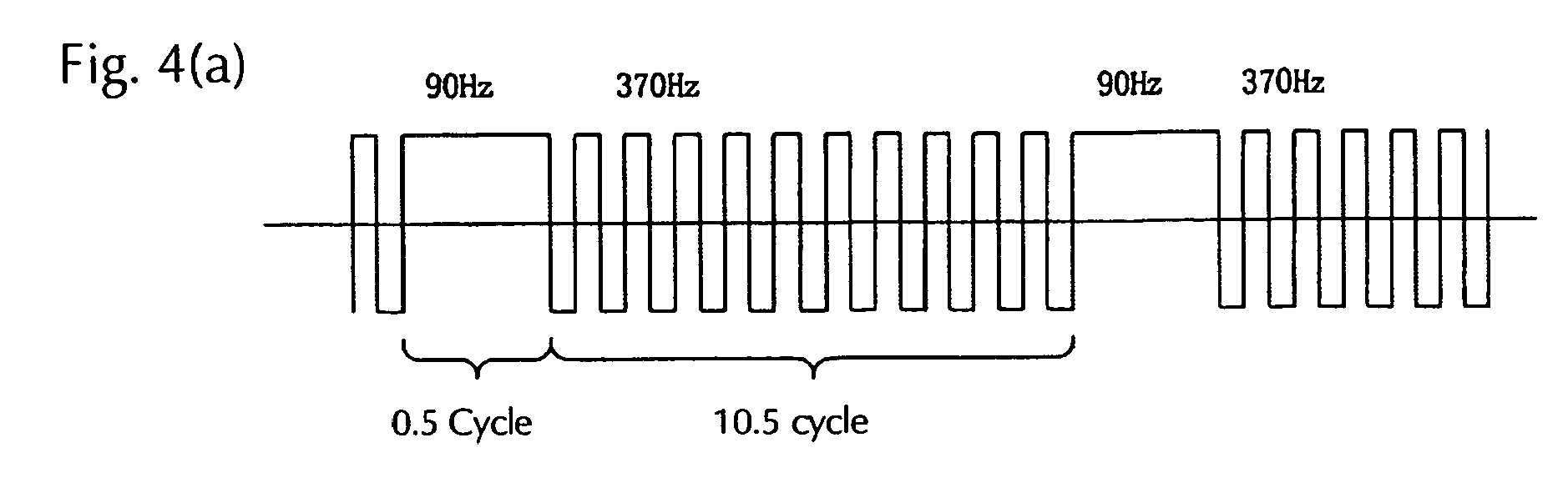
- the drive frequency outputted from the full bridge part U2 in the present implementation is based on a waveform wherein a high frequency (the basic frequency) and a low frequency being lower than that are combined, and for example an implementation of the low frequency for only 0.5 cycle after the high frequency has been implemented for a specified time or a specified number of cycles is repeated in a chronological order.
- the high frequency is the basic frequency when the high pressure discharge lamp is lighting steadily
- the low frequency is the frequency of the alternating current being supplied at the steady state lighting.
- the basic frequency is selected from a range between 60 and 1000 Hz
- the low frequency is a frequency which is lower that the basic frequency being selected from the range between 60 and 1000 Hz, and which is selected from a range between 5 and 200 Hz.
- the low frequency has a length of a half cycle, and the interval from one generation of the alternating current with the low frequency to the next generation of the alternating current with the low frequency is at most 120 seconds (0.01 second to 120 seconds).
- the frequency and the interval for the insertion of the low frequency are chosen in relation to the design of the discharge lamp and especially the thermal design of the electrodes.
- the drive signals for the full bridge circuit part U2 are determined in the controller U4 as follows.
- a rectangular wave signal having a duty (on/off rate) of 50 % is generated and outputted by the high frequency generating part 60 at a high frequency (the basic frequency). If the R-side is selected by the selector 80 the signal of the high frequency generating part 60 is sent via the selector 80 to the driver 51.
- the gate signals G1 to G4 are supplied from the driver 51 to the switching elements Q1 to Q4 of the full bridge circuit part U2, and the switching elements Q1 to Q4 are driven with a frequency corresponding to the high frequency signal. Then a rectangular wave-shaped alternating current voltage with the frequency of the high frequency signal is generated by the full bridge circuit part U2. This alternating current voltage is supplied to the discharge lamp 10.
- the number of cycles of the high frequency signal from the high frequency generating part 60 is counted by the cycle number counter 61.
- the count set value controller 62 has the function to hold a set value for the cycle number counter 61, and if the number of cycles counted by the cycle number counter 61 corresponds to said set value, that is, when the implementation of the high frequency signal for a specified number of cycles has ended, a signal S' is outputted by the counter and the selector 80 switches to the S-side. At the same time the operation of the high frequency generating part 60 is stopped and the low frequency generating part 70 is started.
- a rectangular wave signal having a duty of 50 % is generated and outputted from the low frequency generating part 70 at a low frequency.
- the selector 80 switches to the S-side, the low frequency signal outputted from the low frequency generating part 70 is sent to the driver 51.
- gate signals G1 to G4 are supplied from the driver 51 to the switching elements Q1 to Q4 of the full bridge circuit part U2, and the switching elements Q1 to Q4 are driven with a frequency corresponding to the low frequency signal.
- a rectangular wave-shaped alternating current voltage with the frequency of the low frequency signal is generated by the full bridge circuit part U2. This alternating current voltage is supplied to the discharge lamp 10.
- the number of cycles of the signal from the low frequency generating part 70 is counted by the cycle number counter 71.
- the count set value controller 72 has the function to hold a set value for the cycle number counter 71, and if the cycle number counter 71 corresponds to said set value (0.5 cycle), that is, when the implementation of the low frequency signal for a specified number of cycles has ended, a signal R' is outputted by the counter, the selector 80 switches to the R-side, the low frequency generating part 70 is stopped and the high frequency generating part 60 is started. As by means of this an output from the high frequency generating part 60 to the driver 51 is performed, the full bridge circuit part U2 again outputs the alternating current voltage with the high frequency.
- the control process of the present implementation is characterized in that said count set value controllers 62, 72 are switched or controlled sequentially in the course of time and it is possible to change them in the course of lighting.
- the low frequency is arranged at one side of the electrodes only under said parameters and a specified time has passed, the low frequency is arranged unilaterally at the other electrode. This is possible by changing the count set value controller 62 from 10.5 cycles to 11 cycles only once.
- the sequence control of sequence thereof is performed by the count set value controller 62.
- Fig.4 shows an example of the output waveform before and after the polarity change.
- the vertical axis represents the current while the horizontal axis expresses the time.
- the output waveform of Fig. 4(a) has been maintained for, for example, 5 s (seconds)
- the number of cycles of the basic frequency is changed to 11 cycles (omitted in the drawing)
- the polarity of the low cycle frequency is reverted and the waveform of Fig. 4(b) is formed. This period also is maintained for, for example, 5 s.
- the period during which the low frequency with one polarity is supplied consecutively is not limited to 5 s, it suffices if it is a period selected from a range from 0.5 s to 10 s.
- Fig. 5 is a view explaining the temperature changes at the electrode tip ends.
- the temperature of the electrode 20a of the side at which the half cycle low frequency is arranged and which becomes the anode cycle increases. Because directly after the supply of the alternating current with the low frequency the alternating current with the basic frequency being a high frequency is supplied, the state of the relatively high electrode temperature is maintained. In this state the next low frequency current with the same polarity is supplied. Because the amount of the heating becomes higher with the increase of the quantity of the electrodes received by the electrode, the electrode of the side sending out the power is heated while the electrode of the side receiving the power is not heated.
- the temperature of the electrode tip end increases and tungsten making up the projection par 21 starts to melt (W melting mode).
- the other electrode 20b of the side becoming the cathode cycle is supplied with current having the basic frequency, but because a current with a low frequency having the opposite polarity is supplied, it reaches a comparatively low temperature, the temperature of the projection 21 is comparatively low and tungsten (W) builds up at the projection 21(W build-up mode).
- the alternating current is supplied such that the waveform with the low frequency having one polarity appears at least twice consecutively sandwiching the alternating current waveform with the basic frequency, so that the melting of W and the build-up of W are performed alternatingly between the one and the other electrode.
- the shape of the electrode tip ends can be maintained in a good condition such as is shown in Fig. 5(c) .
- this polarity reversal operation has a range of, for example, 0.5 to 10 s and is performed smoothly, the generation of phenomena associated with the polarity reversal such as flicker can be avoided.
- the electrode temperature of the electrode at which the low frequency is arranged can be increased, such as was described above.
- the period (s) of the generation of the basic frequency, the period (s) of the generation of the low cycle frequency and the period of the consecutive insertion of the low frequency with the same polarity are set such that the following conditions 1 and 2 are satisfied.
- Condition 1 The period (s) of the generation of the basic frequency is at least the same as and at most a hundred times the period (s) of the generation of the low cycle frequency.
- Condition 2 The period of the consecutive insertion of a low frequency with the same polarity (the holding time) is at least 0.5 s and at most 20 s.
- the setting such as in said condition 1 is done for the following reasons.
- the period of the generation of the basic frequency is too short, the low cycle frequency is generated quite often, and therefore the speed of the temperature increase of the electrode becomes too high, the electrode tip end temperature increases abruptly, and the shape of the projection becomes distorted.
- the period of the generation of the basic frequency is the same as the period (s) of the generation of the low cycle frequency or longer than that, the increase of the tip end temperature is suppressed and the projection can be maintained.
- the period (s) of the generation of the basic frequency is preferably at least the same as the period (s) of the generation of the low cycle frequency.
- the period of the generation of the basic frequency is too long, the effect of increasing the temperature of the electrode is not obtained and the shape of the projections at both electrodes becomes distorted.
- the period (s) of the generation of the basic frequency is at most a hundred times the period (s) of the generation of the low cycle frequency, the effect of a temperature increase is obtained at the electrode operating as the anode at the time of the low cycle frequency and the projection can be maintained.
- the period (s) of the generation of the basic frequency desirably is at least the same as and at most a hundred times the period (s) of the generation of the low cycle frequency.
- the setting such as in condition 2 is done for the following reasons.
- the holding time for the consecutive insertion of a low frequency with the same polarity (the period of the consecutive insertion of a low frequency with the same polarity) is too short, the effect of increasing the temperature of the electrode becomes small, the electrode tip end tapers and the shape of the electrode cannot be maintained.
- a holding time of 0.2 s is too short and no sufficient effect is obtained. If the holding time is set to 0.5 s, it happens that the effect of a temperature increase is obtained at the anode cycle sided electrode during the period of the low cycle frequency. Because the polarity is switched at 0.5 s, naturally the electrode tip end temperature can be brought to an appropriate region at both electrodes and the projections can be maintained.
- the holding time is too long, the temperature of the anode cycle sided electrode becomes too high and the projection melts and vanishes. And as the result of the temperature having become too low at the electrode being the cathode side, tungsten is not supplied to the electrode tip end, the wear-off mode occurs and the shape of the projection becomes distorted.
- the projection at the anode cycle sided electrode melts and the temperature at the electrode being the cathode side becomes too low and the projection becomes distorted.
- the anode cycle sided electrode When the holding time is set to 20 s, the anode cycle sided electrode can be maintained at an appropriate temperature and also the shape of the projection can be maintained. And because the electrode being the cathode changes to the anode cycle with a cycle of 20 s, the temperature does not become too low and an appropriate shape of the projection can be maintained.
- a discharge lamp is supplied with an alternating current wherein a low frequency having one polarity appears with a specified period during the basic frequency at a specified time, and an alternating current wherein a low frequency having the other polarity appears with a specified period during the basic frequency at the next specified time.
- an example where the polarity of the low frequency is not changed step-like but is rather changed smoothly from the low frequency having one polarity to the low frequency having the other polarity will be explained with reference to Fig. 6 .
- Fig. 6 is a simplified timing diagram of a mode of an implementation of the current waveform to the discharge lamp according to the present implementation.
- the waveform of Fig. 6 expresses the situation wherein the waveform is changed from (a) to (i) while taking a specified time.
- a control is performed such that the reversal of the polarity of the asymmetrical waveform is done gradually, and the current value I1b and the current value I1a have the same amperage.
- the switching from the low frequency with one polarity to the low frequency with the other polarity is done by controlling such that the pulse width of the low frequency with one polarity is decreased gradually such as shown in (a) to (d) of the drawing, the low frequency does not appear during the high frequency at (e), and the pulse of the low frequency with the other polarity is increased gradually in (f) to (i).
- This control can be effected by changing the frequency of the low frequency generating part 70 in Fig. 3 .
- the reversal of the polarity of the half cycle low frequency can be done with only small fluctuations of the arc of the discharge lamp and without worries with regard to a motion of the point of origin.
- the shape of the electrode tip ends can be maintained good at all times by using the lamp current waveform according to the present implementation, there are also the side effects that flicker can be reduced even if the power supplied to the high pressure discharge lamp is a power of approximately 70 % of that at the time of the steady state lighting, and a stable arc discharge can be maintained.
- the basis of the drive frequency outputted by the full bridge circuit part U2 in the present implementation is a combination of a high frequency (the basic frequency) and a low frequency being lower than that.
- the high frequency is the basic frequency when the high pressure discharge lamp is lighting steadily
- the low frequency is the frequency of the alternating current being supplied at the steady state lighting.
- the basic frequency is selected from a range between 60 and 1000 Hz
- the low frequency is a frequency which is lower that the basic frequency being selected from the range between 60 and 1000 Hz, and which is selected from a range between 5 and 200 Hz.
- the low frequency has a length of at least a half cycle, the low frequency at the time of an alternating generation of the alternating currents with the basic frequency and the low frequency has a length of at most 5 cycles, and the interval from one generation of the alternating current with the low frequency to the next generation of the alternating current with the low frequency is at most 120 seconds.
- the frequency, the length of the insertion and the interval for the insertion of the low frequency are chosen in relation to the design of the discharge lamp and especially the thermal design of the electrodes.
- the low frequency is less than 5 Hz, and the low frequency is generated consecutively in intervals being less than 0.01 second, and the low frequency is generated consecutively for more than 5 periods, the temperature increase of the electrode tip end becomes too high, because of which not only the secondary projection but also the primary projection being necessary and indispensable for the super high pressure discharge lamp of the present invention vanishes.
- the low frequency exceeds 200 Hz and a low frequency of less than a half cycle is inserted, no sufficient temperature increase of the medium temperature region, where the secondary projection is generated, is obtained, and therefore the generation and the growth of the secondary projection cannot be suppressed. Also if the interval of the generation of the low frequency exceeds 120 seconds, the secondary projection grows up to such an extent during the steady state lighting that it will not be eroded.
- the range of the basic frequency being supplied to the high pressure discharge lamp is between 60 and 1000 Hz.
- the low frequency alternating current is selected from a range between 5 and 200 Hz being lower than the frequency of the alternating current with the basic frequency and has a length of at least a half cycle.
- the length of the low frequency at the time of an alternating generation of the alternating currents with the basic frequency and the low frequency is at most 5 cycles, and the interval from a generation of the alternating current with the low frequency to the next generation of the alternating current with the low frequency is at most 120 seconds.
- the drive signals for the full bridge circuit part U2 are determined in the controller U4 shown in Fig. 3 as follows.
- a rectangular wave signal having a duty (on/off rate) of 50 % is generated and outputted by the high frequency generating part 60 at a high frequency (the basic frequency). If the R-side is selected by the selector 80 the signal of the high frequency generating part 60 is sent via the selector 80 to the driver 51.
- the gate signals G1 to G4 are supplied from the driver 51 to the switching elements Q1 to Q4 of the full bridge circuit part U2, and the switching elements Q1 to Q4 are driven with a frequency corresponding to the high frequency signal. Then a rectangular wave-shaped alternating current voltage with the frequency of the high frequency signal is generated by the full bridge circuit part U2. This alternating current voltage is supplied to the discharge lamp 10.
- the number of cycles of the high frequency signal from the high frequency generating part 60 is counted by the cycle number counter 61.
- the count set value controller 62 has the function to hold a set value for the cycle number counter 61, and if the number of cycles counted by the cycle number counter 61 corresponds to said set value, that is, when the implementation of the high frequency signal for a specified number of cycles has ended, a signal S' is outputted by the counter and the selector 80 switches to the S-side. At the same time the operation of the high frequency generating part 60 is stopped and the low frequency generating part 70 is started.
- a rectangular wave signal having a duty of 50 % is generated and outputted from the low frequency generating part 70 at a low frequency.
- the selector 80 switches to the S-side, the low frequency signal outputted from the low frequency generating part 70 is sent to the driver 51.
- gate signals G1 to G4 are supplied from the driver 51 to the switching elements Q1 to Q4 of the full bridge circuit part U2, and the switching elements Q1 to Q4 are driven with a frequency corresponding to the low frequency signal.
- a rectangular wave-shaped alternating current voltage with the frequency of the low frequency signal is generated by the full bridge circuit part U2. This alternating current voltage is supplied to the discharge lamp 10.
- the number of cycles of the signal from the low frequency generating part 70 is counted by the cycle number counter 71.
- the count set value controller 72 has the function to hold a set value for the cycle number counter 71, and if the cycle number counter 71 corresponds to said set value, that is, when the implementation of the low frequency signal for a specified number of cycles has ended, a signal R' is outputted by the counter, the selector 80 switches to the R-side and the low frequency generating part 70 is stopped and the high frequency generating part 60 is started. As by means of this an output from the high frequency generating part 60 to the driver 51 is performed, the full bridge circuit part U2 again outputs the alternating current voltage with the high frequency.
- the control process of the present implementation is characterized in that the set value for said count set value controller is controlled sequentially in the course of time and it is possible to change it in the course of lighting.
- Fig. 8(a) shows an example of the change pattern of the set value for the number of cycles of the basic frequency wherein the vertical axis represents the number (times) of generation cycles of the basic frequency and the horizontal axis expresses the time.
- Fig. 8(b) shows an example of the waveform of the lamp current supplied to the high pressure discharge lamp 10 from the supply device 30, wherein the vertical axis represents the current value and the horizontal axis expresses the time.
- the period during which the high frequency (basic frequency) is outputted can be shortened gradually by changing the set value such that it is reduced with a rate of change of 1 cycle with every 1 second from the number of maximum cycles Fcy Max having been set in advance.
- the number of minimum cycles Fcy Min having been set in advance is reached as the result of the reduction, it is possible to extend the period during which the high frequency is outputted gradually by an increase of 1 cycle with every 1 second.
- This explanation was made exemplary with a rate of change of 1 cycle with every 1 second, but there is no limitation to these values which can be set arbitrarily.
- a count set value controller 72 for the low frequency is provided, and this value may also be a fixed numerical value of, for example, 1 cycle or 0.5 cycle.
- the time of the generation of the basic frequency and the rate of change of the basic frequency are set such that the following conditions 1 and 2 are satisfied.
- Condition 1 At the time at which the number of cycles reaches the maximum, the time of generation of the basic frequency is made at least twice and at most a thousand times the half cycle (s) of the low cycle frequency.
- the cycle increase/decrease speed is 1 s
- the number of cycles of the basic frequency is increased or decreased for 1 cycle with the passing of each 1 s.
- the setting such as in said condition 1 is done for the following reasons.
- the period of the generation of the basic frequency is too short at the time the number of cycles of the basic frequency reaches the maximum, the width between Fcy Max and Fcy Min becomes small and similar to having almost no swing width, because of which the tip end of the electrode tapers and the shape of the projection becomes distorted.
- the period of the generation of the basic frequency is too long, the time from one generation of the low frequency to the next generation of the low frequency becomes long, the temperature of the electrode becomes low, the region with a low load becomes too long, the wear-off mode occurs and the shape of the projection becomes distorted.
- the setting such as in said condition 2 is done for the following reasons.
- the cycle increase/decrease speed is, for example, 0.2 s, there are 5 cycle increases/decreases during 1 s. In this case it is not possible to change the temperature of the electrode tip end smoothly. There is no effect of the swing, and the temperature of the electrode tip end cannot be heated within a wide range. The electrode tip end shape becomes disordered and it is not possible to maintain a stable discharge.
- the cycle increase/decrease speed is too slow, the time of the high load from the electrode, in other words the state of a low electrode temperature, becomes too long and the projection at the tip end becomes distorted.
- the cycle increase/decrease speed is, for example, 20 s (increase or decrease for one cycle with the passing of each 20 s)
- a decrease of the electrode temperature is induced because the time of the high load is long, and the projection of the tip end cannot be maintained.
- the cycle increase/decrease speed becomes 10 s (increase or decrease for one cycle with the passing of each 10 s)
- Fig. 9 shows an example of the waveform of the lamp current supplied to the high pressure discharge lamp 10 from the supply device 30, wherein the vertical axis represents the current value and the horizontal axis expresses the time.
- Fig. 10 is a view explaining the state of the change of the set value for the number of cycles used to control this current waveform, wherein the vertical axis represents the number of cycles (times) the basic frequency is generated and the horizontal axis expresses the time.
- Fig. 9(a) in this example is the case of the largest number of cycles of the basic frequency (Fcy Max) in the state of operating by a combination of the alternating current with the basic frequency (high frequency) and the alternating current with the low frequency, and the waveform where the period ( ⁇ K) of the supply of the basic frequency is the longest (in other words, the number of times of the generation of the low frequency alternating current is the lowest).
- the waveform is changed in the sequence from (b) to (d).
- the value of the basic frequency is 370 Hz and the value of the low cycle frequency is 92 Hz.
- Fcy Max is 37 (cycles) (in time 100 ms) and Fcy Min is 0 (cycles).
- the number of generations of the low cycle frequency in Fig. 9(a) to Fig. 9(c) is 1 cycle.
- the minimum number of cycles (Fcy Min, in this case 0) is reached from the maximum number of cycles (Fcy Max) by gradually shortening the period during which the high frequency is outputted with a constant speed. Afterwards, it is changed with the constant speed until the maximum cycle number is reached again.
- the period of the supply of the alternating current with the high frequency in this way, the number of times of the generation of the alternating current with the low frequency is increased and decreased.
- the drawing is merely an example, and there is no limitation to this kind of change.
- Fig. 11 is a view explaining the state of the temperature change of the electrode tip ends.
- the period ( ⁇ k) from one generation of the low cycle frequency to the next generation of the low cycle frequency is comparatively long, the number of times the low frequency is outputted per unit time is small, and therefore the region being heated in the vicinity of the tip end of the electrode 20a is confined to a relatively frontal region (the portion (a)). At this time, the temperature of the projection 21 is relatively low and tungsten (W) is built-up with regard to the projection (W build-up mode).
- the region being heated in the vicinity of the tip end of the electrode 20a reaches its maximum size and extends for example up to the rear portion (d) of the electrode 20a.
- a melting of tungsten making up the projection part 21 of the electrode tip end occurs (W melting mode).
- the region being heated of the electrode changes by constantly changing the number of times of the generation of the low frequency by means of increasing and decreasing the number of cycles of the high frequency.
- the period of the basic frequency is changed slowly and gradually, abrupt changes of the shape of the tip end part hardly occur and also abrupt changes of the voltage hardly occur.
- Fig 12 is another example of the set values used to control the current waveform, wherein the vertical axis represents the number of cycles (times) of the generation of the basic frequency and the horizontal axis expresses the time.
- Fig. 13 is an example of the current waveform of the lamp wherein the vertical axis represents the current value and the horizontal axis expresses the time.
- the waveform of Fig. 13 changes in the sequence (a) ⁇ (b) ⁇ (c), and when the period of the output of the basic frequency reaches the minimum cycle number (Fcy Min) at the time tc, the waveform of Fig. 13 changes in the sequence (c) ⁇ (b) ⁇ (a).
- Fig. 14 is another example of the current waveform of the lamp, wherein the vertical axis represents the current value and the horizontal axis expresses the time.
- the generation cycle of the low cycle frequency is 0.5, that is, a half cycle, and the polarity is reverted with each generation of the low frequency (that is, alternatingly).
- the set value for the number of cycles used for the control with this current waveform is Fig. 14(d) .
- the waveform of Fig. 14 changes in the sequence (a) ⁇ (b) ⁇ (c), and when the period of the output of the basic frequency reaches the minimum cycle number (Fcy Min) at the time tc, the waveform of Fig. 14 changes in the sequence (c) ⁇ (b) ⁇ (a).
- the basic frequency is generated as in Fig. 13 .
- Fig. 15(a) to (c) show another example of the cycle set value.
- the vertical axis represents the number of cycles (times) of the generation of the basic frequency
- the horizontal axis expresses the time.
- Fig. 15(a) is a representation wherein the period of the generation of the high frequency is increased with a constant speed from the minimum cycle number (Fcy Min).
- Fcy Min minimum cycle number
- Fcy Max maximum cycle number
- Fig. 15(b) is a representation wherein the period of the generation of the high frequency is increased with a constant speed from the minimum cycle number (Fcy Min) until the maximum cycle number (Fcy Max) is reached.
- the maximum cycle number is reached, it is held in this state for a specified time at this maximum cycle number, and afterwards the period of the generation of the high frequency is decreased gradually with a constant speed from the maximum cycle number (Fcy Max).
- the minimum cycle number (Fcy Min) is reached, it is held in the state for a specified time.
- Fig. 15(c) is a representation wherein, when a specified cycle number is reached in the process of the increase from the minimum cycle number (Fcy Min) to the maximum cycle number (Fcy Max) in example (b), this state is maintained for a specified time, and when a specified cycle number is reached in the process of the decrease from the maximum cycle number (Fcy Max) to the minimum cycle number (Fcy Min), this state is maintained for a specified time.
- the optimal parameters are determined experimentally in advance according to the specification of the lamp, and the control shown in Fig. 15 can be implemented by storing the parameters in the count set value controllers 62, 72.
- each part of the electrodes etc. of the high pressure discharge lamp can be adapted suitably. Further, it is possible to apply the present invention to other kinds of high pressure discharge lamp lighting devices than those used for projectors, and to apply it also for devices being provided with high pressure discharge lamps with an enclosed amount of mercury of less than 0.20 mg/mm 3 (for example 0.12 mg/mm 3 to 0.20 mg/mm 3 ) from which generally the same behavior is demanded.
Landscapes
- Circuit Arrangements For Discharge Lamps (AREA)
Abstract
Description
- This invention relates to a high pressure discharge lamp lighting device comprising a super high pressure discharge lamp optimally used as the light source for a projector etc. and a power supply device.
- As to lamps used as the light source of a projector etc., super high pressure discharge lamps where at least 0.2 mg/mm3 of mercury is enclosed in the interior of the discharge vessel and the pressure at the time of the lighting reaches at least 200 atm are utilized. It is known that in such lamps a projection is formed at the surface of the tip end side of the electrodes at the time of the lighting and a stable lighting condition is maintained by holding the arc at these projections.
- Now, if a high pressure discharge lamp is lighted in the same condition for a long time, a plurality of projections is formed and the tip end surface part of the electrodes may become uneven. It is known that if the surface part of the electrode tip end is in disorder, the discharge position becomes unstable and reduction in brightness and flicker are generated because of motions of the arc.
- As a solution for this problem, the patent literature example 1 describes a method to drive a discharge lamp wherein an alternating current with a frequency selected from a frequency range between 60 and 1000 Hz as the basic frequency at the steady state lighting is supplied and a frequency selected from the range between 5 and 200 Hz being lower than the basic frequency is supplied in specific intervals.
- According to this technique, excessive tungsten adhered to the vicinity of the projections necessary for the discharge melts and the electrode tip ends are cleaned by supplying an alternating current such that the basic frequency being supplied at the time of the steady state lighting and a frequency being lower than the basic frequency are generated alternatingly; and because the shape of the projections can be maintained stable as the molten tungsten is supplied to the projections by means of the surface tension, is becomes possible to achieve a long lifetime of the electrodes.
- Then, the patent literature example 2 discloses a technique by means of which the lifetime of the electrodes is extended by changing the value of the frequency at the time of lighting. But because the technique described in the patent literature example 2 constantly increases and decreases the frequency in the course of time, there is the practical problem that an annoying noise is generated.
- Further, the patent literature example 3 discloses a technique by means of which the wear of the electrodes is reduced and the lifetime of the lamp is extended by periodically changing the lamp power. But with this technique it is not possible to prevent brightness changes because of changes of the power.
-
- Patent literature example 1: Japanese laid-open patent publication
2006-59790 - Patent literature example 2: Japanese laid-open patent publication
2007-280734 - Patent literature example 3: Japanese patent no.
4089627 - It is possible to maintain the shape of the projections of the electrodes stable by supplying a basic frequency alternating current and supplying an alternating current with a frequency being lower than the basic frequency in specified intervals such as described in the patent literature example 1, but even with this previous technique the shape of the electrode tip ends in the vicinity of the projection part is worn and it becomes impossible to maintain a stable discharge if the lighting is continued for a longer period.
- The reason for this is explained with regard to
Fig. 16 . In the state of the beginning of the lighting of the high pressure discharge lamp, a low frequency is supplied repeatedly in constant periods. When this low frequency power is supplied, the peripheral part of the projection is heated and unnecessary projections at the tip end surface of theelectrodes main projection 21 at the tip end such as shown inFig. 16(a) . - But if the high pressure discharge lamp has lighted for a long period, the formation and melting of unnecessary projections is repeated in the same region because the parts (regions) being heated at the tip end of the
electrodes projections 21 of theelectrodes Fig. 16(b) , and the shape of the tip end of theelectrodes - To avoid such a situation it is necessary to induce a change in the electrode temperature, that is, to ensure that the heated portion of the electrode is not fixed to the tip end, such that the temperature of the rear portion of the electrode is increased and the area in which the melting and build-up occurs extends over a wide range.
- To ensure that the heated portion of the electrode is not fixed, it simply suffices to extend the period of the supply of the low frequency.
- But even if the period of the low frequency is simply extended, there is the problem that the temperature of the projection tip end rises abruptly at the time of the increase of the temperature of the rear of the electrode and the projection wears off and decreases.
- Thus, it is possible to maintain the shape of the projection stable by supplying an alternating current with a lower frequency than the basic frequency in specified intervals such as described in the patent literature example 1, but the problem arises that the shape of the electrode tip end in the periphery of the projection part wears off and it is not possible to maintain a stable discharge when the above procedure is continued for a long time.
- The present invention was made to solve this problem, and the object to be solved by the invention is to provide a lighting device wherein the temperature control of the electrodes can be performed precisely, the shape of the projection of the electrode and the shape of the tip end can be maintained optimally for a long time and a long lifetime of the discharge lamp is achieved.
- The above-mentioned object is solved by the present invention in the following way.
- (1) In a lamp lighting device lighting a high pressure discharge lamp wherein mercury is enclosed and a pair of electrodes is disposed opposite to each other in the interior of a discharge vessel made from quartz glass, an alternating current is supplied to the high pressure discharge lamp such that a frequency at the time of the steady state lighting (the frequency at the time of the steady state lighting is referred to as 'basic frequency') and a low frequency alternating current of a half cycle with a lower frequency than the basic frequency appear alternatingly, and the alternating current is supplied such that half cycle wave forms with the same polarity appear consecutively at least twice such that the alternating current wave forms with the basic frequency are sandwiched.
- That is, during the supply of the basic frequency alternating current, a low frequency alternating current of a half cycle having the same polarity is inserted in specified periods and the alternating current is supplied to the high pressure discharge lamp such that the alternating current of a half cycle with the same polarity appears consecutively at least twice.
- Said basic frequency alternating current is an alternating current having a frequency selected from a range between 60 and 1000 Hz, and said low frequency alternating current is an alternating current having a frequency being lower than the frequency of the basic frequency alternating current and being selected from a range between 5 and 200 Hz. The interval from one generation of said low frequency alternating current to the generation of the next low frequency alternating current is at most 120 seconds.
- By means of the consecutively repeated supply of a current of a half cycle with the same polarity having a low cycle frequency to one electrode, the temperature of the electrode at the side becoming the anode cycle can be increased as a whole and the tip end part can be melted (melting mode).
- Then, the low frequency of the cathode cycle is consecutively inserted at the electrode of the opposite side and the temperature decreases further. Therefore, there is little tungsten being melted during this period at the electrode of the side operating as the cathode and W is built-up at the projection part (build-up mode).
- The low frequency of the cathode cycle is supplied consecutively, but because the current with the basic frequency is supplied periodically, the temperature of the electrode does not decrease too much. By means of suitably changing the polarity of the electrode being supplied with the current having the low cycle frequency, it is possible to maintain the evaporation of tungsten and the build-up mode at both electrodes with a good balance, to maintain the shape of the projections (electrodes) optimally and to extend the lifetime of the light source.
- Now, during the supply of the low frequency alternating current with one polarity such as described above it is also possible to gradually increase the frequency of the low frequency (that is, to gradually narrow the pulse width of the low frequency alternating current of a half cycle) until it becomes the same as the basic frequency and to gradually reduce the frequency (that is, to gradually enlarge the pulse width of the low frequency alternating current of a half cycle) after the polarity of the low frequency half cycle has been reverted to the other polarity at the time of the correspondence of the low frequency with the basic frequency.
- (2) In a lamp lighting device lighting a high pressure discharge lamp wherein mercury is enclosed and a pair of electrodes is disposed opposite to each other in the interior of a discharge vessel made from quartz glass, the period of the supply of the frequency at the time of the steady state lighting (the frequency at the time of the steady state lighting is referred to as 'basic frequency') and the period of the supply of the low frequency being a lower frequency than that are controlled such that they are changed gradually so that an excessive heating and melting of the electrode tip end does not occur.
- Concretely, an alternating current is supplied from the power supply device provided in said lamp lighting device to the high pressure discharge lamp such that the frequency at the time of the steady state lighting (the basic frequency) and the low frequency are generated alternatingly, and the period of the supply of the basic frequency is controlled such that it gradually increases and decreases with each specified time. That is, the period of the supply of the basic frequency is controlled such that it becomes gradually shorter (that is, the period of the supply of the low frequency becomes gradually longer) and then the period of the supply of the basic frequency is controlled such that it becomes gradually longer (that is, the period of the supply of the low frequency becomes gradually shorter).
- The basic frequency alternating current is an alternating current with a frequency selected from a range between 60 and 1000 Hz, and the low frequency alternating current is an alternating current with a frequency being lower than the frequency of said basic frequency alternating current and being selected from a range between 5 and 200 Hz and with a length of at least a half cycle, the low frequency at the time the alternating currents of the basic frequency and the low frequency are generated alternatingly has a length of at most 5 cycles, and the interval from one generation of the low frequency alternating current to the generation of the next low frequency alternating current is at most 120 seconds.
- When the period of the supply of the frequency at the time of the steady state lighting (the basic frequency) is shortened, the number of times the low frequency alternating current is generated per unit time increases. By gradually increasing the number of times the low frequency alternating current is generated, the portion being heated at the electrode is gradually enlarged and the surface area of the electrode being heated to supply tungsten to the projection broadens. Of course, during the state in which the number of times of the supply of the low frequency is high, the electrode is worn off as a whole because of an overall increase of the temperature of the electrode.
- Now, further the supply period of the basic frequency is changed such that it is gradually changed from a state in which the period of the supply of current with the basic frequency is short to a state in which it is long. By means of this the number of times the low frequency is generated gradually decreases, the temperature of the electrode decreases and the wear of the electrode and the vanishing of the projection are suppressed.
- By means of repeating this operation, a time period during which tungsten melts in a wide range and a time period during which there is no such melting are created alternatingly. With other words, the shape of the projection (electrode) is maintained optimally and the lifetime of the light source is extended by switching (temporally changing) the region in which the electrode is heated.
- Then, by means of changing the periods of the supply of the current with the basic frequency and that with the low frequency not abruptly but gradually, flicker of the lamp can be avoided.
- That is, in case of a momentary switching from the basic frequency to the current having only the low cycle frequency, the same flicker as in case of the occurrence of a power change of the lamp will be perceived by the human eye because of the abrupt change of the frequency. When the change between the basic frequency and the low cycle frequency is periodic and a smooth change, it will not be perceived as flicker.
- By means of the present invention the following results can be obtained.
- (1) By supplying a low cycle frequency current of a half cycle a plurality of times consecutively to one electrode and then changing the polarity of the low frequency and supplying a low cycle frequency current of a half cycle a plurality of times to the other electrode the melting of tungsten and the build-up of tungsten are performed alternatingly among the one electrode and the other electrode, an evaporation and a build-up mode of tungsten with a good balance can be maintained, the shape of the projections (electrodes) can be kept optimally and the lifetime of the light source can be extended.
- (2) By performing the polarity reversal such that the low cycle frequency is gradually approximated to the basic frequency, the temperature change of the electrodes becomes smooth and flicker at the time of the reversal can be reduced.
- (3) By supplying a low cycle frequency current of a half cycle a plurality of times consecutively to one electrode and then changing the polarity of the low frequency and supplying a low cycle frequency current of a half cycle a plurality of times to the other electrode, the shape of the tip end of the electrodes can always be kept good, and the generation of flicker is reduced and a stable arc discharge can be maintained even if the power supplied to the high pressure discharge lamp should be approximately 70 % of the power at the time of the steady state lighting.
- (4) By controlling a lighting device lighting a high pressure discharge lamp wherein mercury is enclosed and a pair of electrodes is disposed opposite to each other in the discharge vessel such that the period of the supply of the basic frequency gradually increases and decreases with each specified time, a time period during which tungsten melts in a wide range and a time period during which there is no such melting can be created alternatingly, the shape of the projections of the electrodes can be kept optimally and the lifetime of the light source can be extended.
- (5) By controlling such that the period of the supply of the basic frequency current is not changed abruptly but is increased and decreased gradually, flicker of the lamp can be avoided. Then, by slowly and gradually changing the period of the basic frequency, abrupt changes of the projection parts hardly occur and also sudden fluctuations of the lamp voltage hardly occur.
-
-
Fig. 1 is a sectional view of a high pressure discharge lamp according to present implementations; -
Fig. 2 is a view wherein the tip ends of the electrodes according to the present implementations are shown schematically; -
Fig. 3 is a circuit diagram of the power supply device for lighting the high pressure discharge lamp of the present implementations; -
Fig. 4 is a view showing an example of the waveform of the lamp current supplied to the high pressure discharge lamp from a power supply device according to a first implementation of the present invention; -
Fig. 5 is a view explaining the temperature state and the wear state of the electrode tip ends according to the first implementation of the present invention; -
Fig. 6 is a view showing another example (1) of the waveform of the lamp current according to the first implementation of the present invention; -
Fig. 7 is a view showing another example (2) of the waveform of the lamp current according to the first implementation of the present invention; -
Fig. 8 is a view showing an example of the pattern of change of the set value for the number of cycles with the basic frequency and an example of the waveform of the lamp current supplied to the high pressure discharge lamp; -
Fig. 9 is a view showing an example of the waveform of the lamp current supplied to the high pressure discharge lamp from a power supply device according to a second implementation of the present invention; -
Fig. 10 is a view explaining the pattern of change of the set value used for the current waveform control according to the second implementation of the present invention; -
Fig. 11 is a view explaining the temperature state and the wear state of the electrode tip ends according to the second implementation of the present invention; -
Fig. 12 is a view showing another example to explain the state of the change of the set value used for the current waveform control according to the second implementation of the present invention; -
Fig. 13 is a view showing another example (1) of the waveform of the lamp current according to the second implementation of the present invention; -
Fig. 14 is a view showing another example (2) of the waveform of the lamp current according to the second implementation of the present invention; -
Fig. 15 is a view showing another example of the pattern of change of the set value used for the current waveform control according to the second implementation of the present invention; and -
Fig. 16 is a view explaining the temperature state and the wear state of the electrode tip ends according to the state of the art. -
Fig. 1 is a sectional view of a high pressure discharge lamp according to implementations of the present invention. - The high
pressure discharge lamp 10 has an approximately sphericallight emission part 11 formed by a discharge vessel made from quartz glass. In the interior of this light emission part 11 a pair ofelectrodes portion 12 is formed. In the sealing portion 12 ametal foil 13 for the power supply made from molybdenum is embedded air-tightly by means of, for example, shrink sealing. The shaft part of theelectrode metal foil 13, and an external lead is connected to the other end of themetal foil 13. Power is supplied from a power supply device (30). - Mercury, a noble gas and a halogen are enclosed in the
light emission part 11. Mercury serves to obtain radiation light with the necessary visible light wavelength, for example a wavelength from 360 to 780 nm. To give a concrete value, at least 0.20 mg/mm3 of mercury are enclosed. Although the enclosed amount differs according to the temperature conditions, the pressure in the interior of the discharge vessel during the lighting is rendered a high vapor pressure of at least 200 atm. By enclosing even more mercury, high pressure discharge lamps with a high mercury vapor pressure of at least 250 atm or at least 300 atm during the lighting can be produced, and with the increase of the mercury vapor pressure light sources suitable for projectors can be implemented. - The noble gas, for example argon gas, is enclosed in an amount of approximately 13 kPa. The function thereof is to improve the starting characteristics of the lighting.
- As to the halogen, iodine, bromine or chlorine is enclosed in the state of a compound with mercury or another metal. The enclosed halogen amount is selected from a range from 10-6 µmol/mm3 to 10-2 µmol/mm3. The function of the halogen is to extend the lifetime by utilizing the so-called halogen cycle, and in case of extremely small-scale lamps with an extremely high lighting vapor pressure such as the high pressure discharge lamp of the present invention it has also the effect of preventing a devitrification of the discharge vessel.
- To give numerical values for the high pressure discharge lamp, for example the maximum outer diameter of the light emission part is 9.4 mm, the electrode spacing is 1.0 mm, the internal volume of the discharge vessel is 55 mm3, the rated voltage is 70 V, the rated current is 180 W and the power is supplied by means of an alternating current.
- This kind of high pressure discharge lamp is installed in projectors the size thereof being more and more reduced, and while an extremely small size is requested with regard to the overall dimensions, on the other hand also a high light emission and light intensity are demanded. Therefore, the thermal influence in the light emission part becomes strong. The tube wall load value of the lamp becomes 0.8 to 2.5 W/mm2 and concretely 2.4 W/mm2.
- When a lamp having such a high mercury vapor pressure and tube wall load value is mounted in a presentation device such as a projector or an overhead projector, radiation light with a good color rendering property can be provided.
-
Fig. 2 is an explanatory view wherein the tip ends of the electrodes shown inFig. 1 are shown schematically, and explains the projections formed at the electrode tip ends during the operation of the lamp. Theelectrodes spherical part 201 and ashaft part 202, and aprojection 21 is formed at the tip end of thespherical part 201. Thisprojection 21 is formed by a condensation of molten tungsten at the electrode tip end at the time of the lighting of the lamp. - Next, the lamp lighting device according to implementations of the present invention is explained with regard to
Fig. 3 . InFig. 3 , the lamp lighting device comprises apower supply device 30 for lighting a highpressure discharge lamp 10 and the high pressure discharge lamp. - The
power supply device 30 comprises a step-down chopper circuit U1 being supplied with a direct current voltage Vdc and reducing it, a full bridge inverter circuit U2 (in the following referred to as 'full bridge circuit') being connected to the output side of the step-down chopper circuit U1, transforming the direct current voltage to an alternating current voltage and supplying it to thedischarge lamp 10, a starter circuit U3 consisting of a coil Lh and a capacitor Ch being connected in series to the highpressure discharge lamp 10, adriver 51 driving switching elements Q1 to Q4 of the full bridge circuit U2, and a controller U4. - The controller U4 may consist of a processing device such as, for example, a microprocessor, and the functions and the configuration thereof are shown in this drawing by means of a block diagram.
- In
Fig. 3 , the step-down chopper circuit U1 comprises a switching element Qx and an inductor Lx connected to the plus side power source terminal being supplied with direct current voltage Vdc, a diode Dx the cathode side thereof being connected between the connection point of the switching element Qx and the inductor Lx and the minus side power source terminal, a smoothing capacitor Cx connected to the output side of the inductor Lx, and a resistor Rx for the current detection being connected between the minus side of the smoothing capacitor Cx and the anode side of the diode Dx. - Said switching element Qx is driven by the gate signal Gx outputted by the controller U4, and by means of driving the switching element Qx with a specified duty the input direct current voltage Vdc is stepped down to a voltage corresponding to this duty. At the output side of the step-down chopper circuit U1 a series circuit Vx of a resistor for the voltage detection is provided.
- The full bridge circuit U2 comprises the switching elements Q1 to Q4 which are connected bridge-shaped. These switching elements Q1 to Q4 are driven by gate signals G1 to G4 outputted by the
driver 51, and by means of bringing the switching elements Q1, Q4 and the switching elements Q2, Q3, which are arranged at opposing corners, into the on-state alternatingly, a rectangular wave shaped alternating current is generated between the connection point of the switching elements Q1, Q2 and the connection point of the switching elements Q3, Q4. - The starter circuit U3 comprises a coil Lh and a capacitor Ch. By means of outputting the resonant frequency of the resonant circuit consisting of the coil Lh and the capacitor Ch from the bridge circuit U2, a high voltage can be generated in the capacitor Ch because of the resonance effect thereof.
- Therefore, the starter circuit U3 is operated with a high frequency only at the time of starting, the high voltage is applied to both ends of the
discharge lamp 10, and the lamp is lighted. - When, in said circuit, the drive frequency of the full bridge circuit U2 is changed at the time of the steady state lighting of the lamp, this can be effected by regulating the switching period of the switching elements Q1 to Q4 of the full bridge circuit U2 or by means of regulating the operating duty of the switching element Qx of the step-down chopper circuit U1 by the output voltage.
- The switching element Qx of the step-down chopper circuit U1 is switched on/off according to the duty of the gate signal Gx outputted by the controller U4, and the power supplied to the
lamp 10 changes. That is, in case of powering up the duty of Qx is decreased and the control of the gate signal Gx is performed such that a power value corresponding to the inputted power regulation signal value is obtained. - The controller U4 comprises a
power controller 52 controlling the lamp power, a highfrequency generating part 60 generating a signal of a high frequency (the basic frequency), a firstcycle number counter 61 counting the number of cycles of the high frequency signal outputted by the highfrequency generating part 60, a first count setvalue controller 62 holding a set value for the count value of the high frequency signal outputted by the highfrequency generating part 60, a lowfrequency generating part 70 generating a low frequency signal with a frequency being lower than the basic frequency, a secondcycle number counter 71 counting the number of cycles of the low frequency signal outputted by the lowfrequency generating part 70, a second count setvalue controller 72 holding a set value for the count value of the low frequency signal outputted by the lowfrequency generating part 70, and aselector 80 selectively outputting one of the outputs of the highfrequency generating part 60 and the lowfrequency generating part 70 to thedriver 51. - The
power controller 52 determines the lamp current I and the lamp voltage V from the voltage at both ends of the resistor Rx for the current detection and the voltage outputted by the resistor Vx for the voltage detection and calculates the lamp power and controls the duty of the switching element Qx of the step-down chopper circuit U1 such that this power corresponds to the lighting power command. - In the following, a first and a second implementation of the present invention in the high pressure discharge lamp lighting device described in
Figs. 1 to 3 will be explained. - The drive frequency outputted from the full bridge part U2 in the present implementation is based on a waveform wherein a high frequency (the basic frequency) and a low frequency being lower than that are combined, and for example an implementation of the low frequency for only 0.5 cycle after the high frequency has been implemented for a specified time or a specified number of cycles is repeated in a chronological order.
- Here, the high frequency is the basic frequency when the high pressure discharge lamp is lighting steadily, and the low frequency is the frequency of the alternating current being supplied at the steady state lighting.
- As is disclosed in the patent literature example 1, the basic frequency is selected from a range between 60 and 1000 Hz, and the low frequency is a frequency which is lower that the basic frequency being selected from the range between 60 and 1000 Hz, and which is selected from a range between 5 and 200 Hz.
- The low frequency has a length of a half cycle, and the interval from one generation of the alternating current with the low frequency to the next generation of the alternating current with the low frequency is at most 120 seconds (0.01 second to 120 seconds). The frequency and the interval for the insertion of the low frequency are chosen in relation to the design of the discharge lamp and especially the thermal design of the electrodes.
- Such as is described in the patent literature example, by means of supplying an alternating current with a waveform wherein the high frequency and the low frequency are combined it becomes possible to melt the electrode tip end part by supplying the low frequency alternating current and to prevent the generation of unnecessary projections except the projection becoming the point of origin of the arc.
- The drive signals for the full bridge circuit part U2 are determined in the controller U4 as follows.
- In
Fig. 3 , first a rectangular wave signal having a duty (on/off rate) of 50 % is generated and outputted by the highfrequency generating part 60 at a high frequency (the basic frequency). If the R-side is selected by theselector 80 the signal of the highfrequency generating part 60 is sent via theselector 80 to thedriver 51. - By means of this the gate signals G1 to G4 are supplied from the
driver 51 to the switching elements Q1 to Q4 of the full bridge circuit part U2, and the switching elements Q1 to Q4 are driven with a frequency corresponding to the high frequency signal. Then a rectangular wave-shaped alternating current voltage with the frequency of the high frequency signal is generated by the full bridge circuit part U2. This alternating current voltage is supplied to thedischarge lamp 10. - The number of cycles of the high frequency signal from the high
frequency generating part 60 is counted by thecycle number counter 61. The count setvalue controller 62 has the function to hold a set value for thecycle number counter 61, and if the number of cycles counted by thecycle number counter 61 corresponds to said set value, that is, when the implementation of the high frequency signal for a specified number of cycles has ended, a signal S' is outputted by the counter and theselector 80 switches to the S-side. At the same time the operation of the highfrequency generating part 60 is stopped and the lowfrequency generating part 70 is started. - A rectangular wave signal having a duty of 50 % is generated and outputted from the low
frequency generating part 70 at a low frequency. When theselector 80 switches to the S-side, the low frequency signal outputted from the lowfrequency generating part 70 is sent to thedriver 51. By means of this, gate signals G1 to G4 are supplied from thedriver 51 to the switching elements Q1 to Q4 of the full bridge circuit part U2, and the switching elements Q1 to Q4 are driven with a frequency corresponding to the low frequency signal. Then a rectangular wave-shaped alternating current voltage with the frequency of the low frequency signal is generated by the full bridge circuit part U2. This alternating current voltage is supplied to thedischarge lamp 10. - At the same time, the number of cycles of the signal from the low
frequency generating part 70 is counted by thecycle number counter 71. The count setvalue controller 72 has the function to hold a set value for thecycle number counter 71, and if thecycle number counter 71 corresponds to said set value (0.5 cycle), that is, when the implementation of the low frequency signal for a specified number of cycles has ended, a signal R' is outputted by the counter, theselector 80 switches to the R-side, the lowfrequency generating part 70 is stopped and the highfrequency generating part 60 is started. As by means of this an output from the highfrequency generating part 60 to thedriver 51 is performed, the full bridge circuit part U2 again outputs the alternating current voltage with the high frequency. - In the following, the example established in the foregoing is shown.
- high frequency generating part 60: 370 Hz
- count set value controller 62: 10.5 cycles
- low frequency generating part 70: 90 Hz
- count set value controller 72: 0.5 cycle
- The control process of the present implementation is characterized in that said count set
value controllers value controller 62 from 10.5 cycles to 11 cycles only once. The sequence control of sequence thereof is performed by the count setvalue controller 62. -
Fig.4 shows an example of the output waveform before and after the polarity change. In the drawing, the vertical axis represents the current while the horizontal axis expresses the time. After the output waveform ofFig. 4(a) has been maintained for, for example, 5 s (seconds), the number of cycles of the basic frequency is changed to 11 cycles (omitted in the drawing), the polarity of the low cycle frequency is reverted and the waveform ofFig. 4(b) is formed. This period also is maintained for, for example, 5 s. - As is shown in
Fig. 4(a) or inFig. 4(b) , the period during which the low frequency with one polarity is supplied consecutively is not limited to 5 s, it suffices if it is a period selected from a range from 0.5 s to 10 s. - The specification of the lamp used in the present implementation and the operating conditions of the lamp are as follows.
- When the lamp was lighted as shown in
Fig. 4 under the following specification and conditions such that the low frequency alternating current of a half cycle was inserted while the alternating current with the basic frequency was supplied, and for this low frequency alternating current an alternating current of a half cycle and with the same polarity was supplied at least twice consecutively to the electrode of the high pressure discharge lamp, it was possible to maintain the tungsten evaporation and build-up modes with a good balance and to keep the shape of the projections (electrodes) optimally. -
- rated power: 270 W
- rated voltage: 80 V
- internal volume of the light emission part: 80 mm3
- electrode spacing: 1.2 mm
- Enclosed substances
- amount of mercury: 280 mg/mm3
- noble gas (concretely argon gas): 13 kPa
- halogen amount (for example iodine, bromine, chlorine): 10-6 to 10-2 µmol/mm3
- Operating conditions of the lamp
- basic frequency: 370Hz
- low cycle frequency: 46.25 Hz
- insertion interval of low frequency: 200 ms
- holding time (at one polarity): 1 s
-
Fig. 5 is a view explaining the temperature changes at the electrode tip ends. - First, in
Fig. 5(a) , the temperature of theelectrode 20a of the side at which the half cycle low frequency is arranged and which becomes the anode cycle (the electrode sending out the power, that is, the electrode becoming the plus side by being supplied with the half cycle low frequency) increases. Because directly after the supply of the alternating current with the low frequency the alternating current with the basic frequency being a high frequency is supplied, the state of the relatively high electrode temperature is maintained. In this state the next low frequency current with the same polarity is supplied. Because the amount of the heating becomes higher with the increase of the quantity of the electrodes received by the electrode, the electrode of the side sending out the power is heated while the electrode of the side receiving the power is not heated. - During such a supply for, for example, 5 s, the temperature of the electrode tip end increases and tungsten making up the
projection par 21 starts to melt (W melting mode). - In the meantime, the
other electrode 20b of the side becoming the cathode cycle is supplied with current having the basic frequency, but because a current with a low frequency having the opposite polarity is supplied, it reaches a comparatively low temperature, the temperature of theprojection 21 is comparatively low and tungsten (W) builds up at the projection 21(W build-up mode). - When, thereafter, the polarity is reversed and the half cycle low frequency is arranged at the side of the
other electrode 20b, the temperature of the tip end of theelectrode 20b rises such as is shown inFig. 5(b) and tungsten making up theprojection 21 starts to melt (W melting mode). - In this way, the alternating current is supplied such that the waveform with the low frequency having one polarity appears at least twice consecutively sandwiching the alternating current waveform with the basic frequency, so that the melting of W and the build-up of W are performed alternatingly between the one and the other electrode. By means of this, the shape of the electrode tip ends can be maintained in a good condition such as is shown in
Fig. 5(c) . - Because this polarity reversal operation has a range of, for example, 0.5 to 10 s and is performed smoothly, the generation of phenomena associated with the polarity reversal such as flicker can be avoided.
- When the low frequency is supplied while the polarity of the low frequency is changed alternatingly, one electrode is heated at the time of one polarity but the other electrode is not heated and the temperature thereof becomes low. Therefore, when the polarity is changed alternatingly, the electrodes are heated and cooled repeatedly and the temperature does not rise so much that tungsten is melted. By repeatedly supplying a voltage with the same polarity to one electrode such as in the present implementation, the electrode temperature of the electrode at which the low frequency is arranged (the electrode at the side sending out the power) can be increased, such as was described above.
- Desirably, the period (s) of the generation of the basic frequency, the period (s) of the generation of the low cycle frequency and the period of the consecutive insertion of the low frequency with the same polarity (referred to as 'holding time') are set such that the following conditions 1 and 2 are satisfied.
- Condition 1: The period (s) of the generation of the basic frequency is at least the same as and at most a hundred times the period (s) of the generation of the low cycle frequency.
- Condition 2: The period of the consecutive insertion of a low frequency with the same polarity (the holding time) is at least 0.5 s and at most 20 s.
- The setting such as in said condition 1 is done for the following reasons.
- If the period of the generation of the basic frequency is too short, the low cycle frequency is generated quite often, and therefore the speed of the temperature increase of the electrode becomes too high, the electrode tip end temperature increases abruptly, and the shape of the projection becomes distorted. When the period of the generation of the basic frequency is the same as the period (s) of the generation of the low cycle frequency or longer than that, the increase of the tip end temperature is suppressed and the projection can be maintained.
- Therefore, the period (s) of the generation of the basic frequency is preferably at least the same as the period (s) of the generation of the low cycle frequency.
- If, on the other hand, the period of the generation of the basic frequency is too long, the effect of increasing the temperature of the electrode is not obtained and the shape of the projections at both electrodes becomes distorted. When the period (s) of the generation of the basic frequency is at most a hundred times the period (s) of the generation of the low cycle frequency, the effect of a temperature increase is obtained at the electrode operating as the anode at the time of the low cycle frequency and the projection can be maintained.
- Thus, the period (s) of the generation of the basic frequency desirably is at least the same as and at most a hundred times the period (s) of the generation of the low cycle frequency.
- The setting such as in condition 2 is done for the following reasons.
- If the holding time for the consecutive insertion of a low frequency with the same polarity (the period of the consecutive insertion of a low frequency with the same polarity) is too short, the effect of increasing the temperature of the electrode becomes small, the electrode tip end tapers and the shape of the electrode cannot be maintained.
- For example, a holding time of 0.2 s is too short and no sufficient effect is obtained. If the holding time is set to 0.5 s, it happens that the effect of a temperature increase is obtained at the anode cycle sided electrode during the period of the low cycle frequency. Because the polarity is switched at 0.5 s, naturally the electrode tip end temperature can be brought to an appropriate region at both electrodes and the projections can be maintained.
- If the holding time is too long, the temperature of the anode cycle sided electrode becomes too high and the projection melts and vanishes. And as the result of the temperature having become too low at the electrode being the cathode side, tungsten is not supplied to the electrode tip end, the wear-off mode occurs and the shape of the projection becomes distorted.
- When the holding time is set to, for example, 50 s, the projection at the anode cycle sided electrode melts and the temperature at the electrode being the cathode side becomes too low and the projection becomes distorted.
- When the holding time is set to 20 s, the anode cycle sided electrode can be maintained at an appropriate temperature and also the shape of the projection can be maintained. And because the electrode being the cathode changes to the anode cycle with a cycle of 20 s, the temperature does not become too low and an appropriate shape of the projection can be maintained.
- In the above description it has been explained that a discharge lamp is supplied with an alternating current wherein a low frequency having one polarity appears with a specified period during the basic frequency at a specified time, and an alternating current wherein a low frequency having the other polarity appears with a specified period during the basic frequency at the next specified time. Now, an example where the polarity of the low frequency is not changed step-like but is rather changed smoothly from the low frequency having one polarity to the low frequency having the other polarity will be explained with reference to
Fig. 6 . -
Fig. 6 is a simplified timing diagram of a mode of an implementation of the current waveform to the discharge lamp according to the present implementation. - For the reversal of the polarity of an asymmetrical waveform, the waveform of
Fig. 6 expresses the situation wherein the waveform is changed from (a) to (i) while taking a specified time. In the drawing, a control is performed such that the reversal of the polarity of the asymmetrical waveform is done gradually, and the current value I1b and the current value I1a have the same amperage. - In this example, the switching from the low frequency with one polarity to the low frequency with the other polarity is done by controlling such that the pulse width of the low frequency with one polarity is decreased gradually such as shown in (a) to (d) of the drawing, the low frequency does not appear during the high frequency at (e), and the pulse of the low frequency with the other polarity is increased gradually in (f) to (i). This control can be effected by changing the frequency of the low
frequency generating part 70 inFig. 3 . - By means of this, the reversal of the polarity of the half cycle low frequency can be done with only small fluctuations of the arc of the discharge lamp and without worries with regard to a motion of the point of origin.
- Because, as was explained above, the shape of the electrode tip ends can be maintained good at all times by using the lamp current waveform according to the present implementation, there are also the side effects that flicker can be reduced even if the power supplied to the high pressure discharge lamp is a power of approximately 70 % of that at the time of the steady state lighting, and a stable arc discharge can be maintained.
- In the present implementation it is also possible to supply the low frequency while changing the frequency value, as is shown in
Fig. 7(a) . Then, it is also possible, such as shown inFig. 7(b) , to change the insertion interval of the low frequency or to combine these possibilities. - The basis of the drive frequency outputted by the full bridge circuit part U2 in the present implementation is a combination of a high frequency (the basic frequency) and a low frequency being lower than that.
- Here, the high frequency is the basic frequency when the high pressure discharge lamp is lighting steadily, and the low frequency is the frequency of the alternating current being supplied at the steady state lighting.
- As is disclosed in the patent literature example, the basic frequency is selected from a range between 60 and 1000 Hz, and the low frequency is a frequency which is lower that the basic frequency being selected from the range between 60 and 1000 Hz, and which is selected from a range between 5 and 200 Hz.
- The low frequency has a length of at least a half cycle, the low frequency at the time of an alternating generation of the alternating currents with the basic frequency and the low frequency has a length of at most 5 cycles, and the interval from one generation of the alternating current with the low frequency to the next generation of the alternating current with the low frequency is at most 120 seconds. The frequency, the length of the insertion and the interval for the insertion of the low frequency are chosen in relation to the design of the discharge lamp and especially the thermal design of the electrodes.
- Such as is described in the patent literature example, by means of supplying an alternating current with a waveform wherein the high frequency and the low frequency are combined, it becomes possible to melt the electrode tip end part by supplying the low frequency alternating current and to prevent the generation of unnecessary projections except the projection becoming the point of origin of the arc.
- When the high pressure discharge lamp is steadily lighted with a frequency between 60 Hz and 1000 Hz, the formation of a secondary projection in the medium temperature region of the electrode surface starts. This secondary projection is a so-called unnecessary projection which practically does not contribute to the discharge. When, if the formation of such a secondary projection has occurred, a switching from the frequency of the steady state lighting to a low frequency is performed, the temperature of the electrode tip end rises during the operation as the anode because the period of the operation as the anode is long. This temperature increase is transmitted to the medium temperature region where the secondary projection is generated, and the electrode surface temperature in this region increases because of which the secondary projection having started to form evaporates, is eroded and vanishes.
- To suppress the generation and growth of a secondary projection, it is, in essence, important to change the temperature of the electrode surface temporally. If the low frequency is less than 5 Hz, and the low frequency is generated consecutively in intervals being less than 0.01 second, and the low frequency is generated consecutively for more than 5 periods, the temperature increase of the electrode tip end becomes too high, because of which not only the secondary projection but also the primary projection being necessary and indispensable for the super high pressure discharge lamp of the present invention vanishes.
- If, on the other hand, the low frequency exceeds 200 Hz and a low frequency of less than a half cycle is inserted, no sufficient temperature increase of the medium temperature region, where the secondary projection is generated, is obtained, and therefore the generation and the growth of the secondary projection cannot be suppressed. Also if the interval of the generation of the low frequency exceeds 120 seconds, the secondary projection grows up to such an extent during the steady state lighting that it will not be eroded.
- According to the present implementation, the range of the basic frequency being supplied to the high pressure discharge lamp is between 60 and 1000 Hz. The low frequency alternating current is selected from a range between 5 and 200 Hz being lower than the frequency of the alternating current with the basic frequency and has a length of at least a half cycle. The length of the low frequency at the time of an alternating generation of the alternating currents with the basic frequency and the low frequency is at most 5 cycles, and the interval from a generation of the alternating current with the low frequency to the next generation of the alternating current with the low frequency is at most 120 seconds. By means of this it becomes possible to obtain the same result as with the previous invention, that is, the result that the generation and the growth of unnecessary projections practically not contributing to the discharge can be suppressed perfectly.
- The drive signals for the full bridge circuit part U2 are determined in the controller U4 shown in
Fig. 3 as follows. - In
Fig. 3 , first a rectangular wave signal having a duty (on/off rate) of 50 % is generated and outputted by the highfrequency generating part 60 at a high frequency (the basic frequency). If the R-side is selected by theselector 80 the signal of the highfrequency generating part 60 is sent via theselector 80 to thedriver 51. - By means of this the gate signals G1 to G4 are supplied from the
driver 51 to the switching elements Q1 to Q4 of the full bridge circuit part U2, and the switching elements Q1 to Q4 are driven with a frequency corresponding to the high frequency signal. Then a rectangular wave-shaped alternating current voltage with the frequency of the high frequency signal is generated by the full bridge circuit part U2. This alternating current voltage is supplied to thedischarge lamp 10. - The number of cycles of the high frequency signal from the high
frequency generating part 60 is counted by thecycle number counter 61. The count setvalue controller 62 has the function to hold a set value for thecycle number counter 61, and if the number of cycles counted by thecycle number counter 61 corresponds to said set value, that is, when the implementation of the high frequency signal for a specified number of cycles has ended, a signal S' is outputted by the counter and theselector 80 switches to the S-side. At the same time the operation of the highfrequency generating part 60 is stopped and the lowfrequency generating part 70 is started. - A rectangular wave signal having a duty of 50 % is generated and outputted from the low
frequency generating part 70 at a low frequency. When theselector 80 switches to the S-side, the low frequency signal outputted from the lowfrequency generating part 70 is sent to thedriver 51. By means of this, gate signals G1 to G4 are supplied from thedriver 51 to the switching elements Q1 to Q4 of the full bridge circuit part U2, and the switching elements Q1 to Q4 are driven with a frequency corresponding to the low frequency signal. Then a rectangular wave-shaped alternating current voltage with the frequency of the low frequency signal is generated by the full bridge circuit part U2. This alternating current voltage is supplied to thedischarge lamp 10. - At the same time, the number of cycles of the signal from the low
frequency generating part 70 is counted by thecycle number counter 71. The count setvalue controller 72 has the function to hold a set value for thecycle number counter 71, and if thecycle number counter 71 corresponds to said set value, that is, when the implementation of the low frequency signal for a specified number of cycles has ended, a signal R' is outputted by the counter, theselector 80 switches to the R-side and the lowfrequency generating part 70 is stopped and the highfrequency generating part 60 is started. As by means of this an output from the highfrequency generating part 60 to thedriver 51 is performed, the full bridge circuit part U2 again outputs the alternating current voltage with the high frequency. - In the following, the example established in the foregoing is shown.
- high frequency generating part 60: 370 Hz
- count set value controller 62: 100.5 cycles
- low frequency generating part 70: 90 Hz
- count set value controller 72: 1 cycle
- The control process of the present implementation is characterized in that the set value for said count set value controller is controlled sequentially in the course of time and it is possible to change it in the course of lighting.
-
Fig. 8(a) shows an example of the change pattern of the set value for the number of cycles of the basic frequency wherein the vertical axis represents the number (times) of generation cycles of the basic frequency and the horizontal axis expresses the time.Fig. 8(b) shows an example of the waveform of the lamp current supplied to the highpressure discharge lamp 10 from thesupply device 30, wherein the vertical axis represents the current value and the horizontal axis expresses the time. - As is shown in
Fig. 8(a) , the period during which the high frequency (basic frequency) is outputted can be shortened gradually by changing the set value such that it is reduced with a rate of change of 1 cycle with every 1 second from the number of maximum cycles Fcy Max having been set in advance. When the number of minimum cycles Fcy Min having been set in advance is reached as the result of the reduction, it is possible to extend the period during which the high frequency is outputted gradually by an increase of 1 cycle with every 1 second. - This explanation was made exemplary with a rate of change of 1 cycle with every 1 second, but there is no limitation to these values which can be set arbitrarily. Here, also a count
set value controller 72 for the low frequency is provided, and this value may also be a fixed numerical value of, for example, 1 cycle or 0.5 cycle. - Desirably, the time of the generation of the basic frequency and the rate of change of the basic frequency are set such that the following conditions 1 and 2 are satisfied.
- Condition 1: At the time at which the number of cycles reaches the maximum, the time of generation of the basic frequency is made at least twice and at most a thousand times the half cycle (s) of the low cycle frequency.
- Condition 2: When the time being necessary for increasing or decreasing the number of cycles of the basic frequency for one cycle is referred to as 'cycle increase/decrease speed (s)', this cycle increase/decrease speed (s) is set to at least 0.5 s and at most 10 s.
- When, for example the cycle increase/decrease speed is 1 s, the number of cycles of the basic frequency is increased or decreased for 1 cycle with the passing of each 1 s.
- The setting such as in said condition 1 is done for the following reasons.
- To keep the shape of the projections good, it is necessary to set the period of the consecutive formation of the basic frequency at the time (Fcy Max) shown in
Fig. 8(a) , at which the number of cycles of the basic frequency reaches the maximum, to an appropriate range. - If the period of the generation of the basic frequency is too short at the time the number of cycles of the basic frequency reaches the maximum, the width between Fcy Max and Fcy Min becomes small and similar to having almost no swing width, because of which the tip end of the electrode tapers and the shape of the projection becomes distorted. To avoid such a problem, it is desirable to set the period of the generation of the basic frequency to at least twice the half cycle of the low cycle frequency.
- If, on the other hand, the period of the generation of the basic frequency is too long, the time from one generation of the low frequency to the next generation of the low frequency becomes long, the temperature of the electrode becomes low, the region with a low load becomes too long, the wear-off mode occurs and the shape of the projection becomes distorted.
- Therefore it is considered desirable to set a range of at most a thousand times for the period of the generation of the basic frequency.
- The setting such as in said condition 2 is done for the following reasons.
- If the cycle increase/decrease speed is too fast, the electrode temperature cannot follow the change thereof, the effect of the swing is not obtained and the shape of the projection becomes distorted.
- If the cycle increase/decrease speed is, for example, 0.2 s, there are 5 cycle increases/decreases during 1 s. In this case it is not possible to change the temperature of the electrode tip end smoothly. There is no effect of the swing, and the temperature of the electrode tip end cannot be heated within a wide range. The electrode tip end shape becomes disordered and it is not possible to maintain a stable discharge.
- When the cycle increase/decrease speed becomes 0.5 s (2 cycle increases/decreases during 1 s), it becomes possible that the temperature of the electrode tip end follows the cycle increases/decreases, and the electrode tip end temperature can be heated within a wide range. As the result, the projection of the tip end can be maintained.
- It is desirable to set the increase/decrease speed of the interval of the generation of the low cycle frequency (the time at which the basic frequency is increased/decreased for 1 cycle) to at least 0.5 s.
- If, on the other hand, the cycle increase/decrease speed is too slow, the time of the high load from the electrode, in other words the state of a low electrode temperature, becomes too long and the projection at the tip end becomes distorted.
- If the cycle increase/decrease speed is, for example, 20 s (increase or decrease for one cycle with the passing of each 20 s), a decrease of the electrode temperature is induced because the time of the high load is long, and the projection of the tip end cannot be maintained. When the cycle increase/decrease speed becomes 10 s (increase or decrease for one cycle with the passing of each 10 s), it becomes possible to control the low temperature and high temperature of the electrode tip end temperature and the projection of the tip end can be maintained.
- Therefore, is desirable to set the increase/decrease speed of the interval of the generation of the low cycle frequency (the time at which the basic frequency is increased/decreased for 1 cycle) to at most 10 s. As long as these set values satisfy the necessary conditions, of course also settings for a step-wise increase or decrease of a plurality of cycles - 2 cycles or 3 cycles - are possible.
- Then, although a detailed explanation thereof will be omitted, there may also be a combination with a technique whereby the frequency of the high frequency generating part or the frequency of the low frequency generating part is changed depending on the lamp voltage value or the lamp current value, and similarly, also an implementation is possible wherein parameters regarding the change of each set value (Fcy Max, Fcy Min) for the number of cycles of the count set
value controllers 62, 67 or of the rate of change in dependence of the lamp voltage or the lamp current are tabulated and the optimal parameters can be selected. - In the following, concrete examples of the current waveform pattern of the present implementation and the change pattern of the set value for the number of cycles in the count set
value controller 62 will be explained. - The specification of the lamp used in the embodiments explained below and the operating conditions of the lamp are as follows.
-
- rated power: 270 W
- rated voltage: 80 V
- internal volume of the light emission part: 80 mm3
- electrode spacing: 1.2 mm
- Enclosed substances
- amount of mercury: 0.28 mg/mm3
- noble gas (concretely argon gas): 13 kPa
- halogen amount (for example iodine, bromine, chlorine): 10-6 to 10-2 µmol/mm3
- Operating conditions of the lamps
- basic frequency: 370 Hz
- low cycle frequency: 46.25 Hz, 92 Hz
- minimum insertion interval of low frequency: 0 ms
- maximum insertion interval of low frequency: 300 ms
- cycle increase/decrease speed: 1 cycle/2 s
-
Fig. 9 shows an example of the waveform of the lamp current supplied to the highpressure discharge lamp 10 from thesupply device 30, wherein the vertical axis represents the current value and the horizontal axis expresses the time.Fig. 10 is a view explaining the state of the change of the set value for the number of cycles used to control this current waveform, wherein the vertical axis represents the number of cycles (times) the basic frequency is generated and the horizontal axis expresses the time. - When the time changes like ta, tb, tc, td ... such as in
Fig. 10 and the set value of the number of cycles changes, the current waveform appears in the sequence (a) → (b) → (c) → (d) such as shown inFig. 9 . When afterwards the time becomes tc', tb', ta' after td, there is the change of (d) → (c) → (b) → (a) inFig. 9 . -
Fig. 9(a) in this example is the case of the largest number of cycles of the basic frequency (Fcy Max) in the state of operating by a combination of the alternating current with the basic frequency (high frequency) and the alternating current with the low frequency, and the waveform where the period (τK) of the supply of the basic frequency is the longest (in other words, the number of times of the generation of the low frequency alternating current is the lowest). - By means of changing the set value from this waveform (a) such that it is reduced from the maximum number of cycles (Fcy Max) having been set in advance with a rate of change of 1 cycle for each specified time (for example for each 1 second), the waveform is changed in the sequence from (b) to (d).
- As to concrete numeric values for the above embodiment, the value of the basic frequency is 370 Hz and the value of the low cycle frequency is 92 Hz. In the state (a), Fcy Max is 37 (cycles) (in
time 100 ms) and Fcy Min is 0 (cycles). The number of generations of the low cycle frequency inFig. 9(a) to Fig. 9(c) is 1 cycle. - As is shown in
Fig. 10 , the minimum number of cycles (Fcy Min, in this case 0) is reached from the maximum number of cycles (Fcy Max) by gradually shortening the period during which the high frequency is outputted with a constant speed. Afterwards, it is changed with the constant speed until the maximum cycle number is reached again. By changing the period of the supply of the alternating current with the high frequency in this way, the number of times of the generation of the alternating current with the low frequency is increased and decreased. The drawing is merely an example, and there is no limitation to this kind of change. -
Fig. 11 is a view explaining the state of the temperature change of the electrode tip ends. - If the period (τk) from one generation of the low cycle frequency to the next generation of the low cycle frequency is comparatively long, the number of times the low frequency is outputted per unit time is small, and therefore the region being heated in the vicinity of the tip end of the
electrode 20a is confined to a relatively frontal region (the portion (a)). At this time, the temperature of theprojection 21 is relatively low and tungsten (W) is built-up with regard to the projection (W build-up mode). - When the number of times of the output of the high frequency gradually decreases and the output of the low frequency gradually increases, the frequency of the occurrence of a high temperature at the electrode increases, the temperature of the projection becomes high, and the region being heated of the electrode tip end extends rearwards.
- When the period of the output of the basic frequency reaches the minimum cycle value (Fcy Min), the region being heated in the vicinity of the tip end of the
electrode 20a reaches its maximum size and extends for example up to the rear portion (d) of theelectrode 20a. A melting of tungsten making up theprojection part 21 of the electrode tip end occurs (W melting mode). - According to the present implementation, the region being heated of the electrode changes by constantly changing the number of times of the generation of the low frequency by means of increasing and decreasing the number of cycles of the high frequency. As the result it becomes possible to maintain the shape of the electrode tip end optimally even if the lamp is lighted for a long time. As, in this embodiment, the period of the basic frequency is changed slowly and gradually, abrupt changes of the shape of the tip end part hardly occur and also abrupt changes of the voltage hardly occur.
-
Fig 12 is another example of the set values used to control the current waveform, wherein the vertical axis represents the number of cycles (times) of the generation of the basic frequency and the horizontal axis expresses the time. Then,Fig. 13 , is an example of the current waveform of the lamp wherein the vertical axis represents the current value and the horizontal axis expresses the time. - When the time changes like ta, tb, tc ... such as is shown in
Fig. 12 , the waveform ofFig. 13 changes in the sequence (a) → (b) → (c), and when the period of the output of the basic frequency reaches the minimum cycle number (Fcy Min) at the time tc, the waveform ofFig. 13 changes in the sequence (c) → (b) → (a). -
Fig. 14 is another example of the current waveform of the lamp, wherein the vertical axis represents the current value and the horizontal axis expresses the time. - In this example, the generation cycle of the low cycle frequency is 0.5, that is, a half cycle, and the polarity is reverted with each generation of the low frequency (that is, alternatingly). The set value for the number of cycles used for the control with this current waveform is
Fig. 14(d) . - That is, when the time changes like ta, tb, tc ..., the waveform of
Fig. 14 changes in the sequence (a) → (b) → (c), and when the period of the output of the basic frequency reaches the minimum cycle number (Fcy Min) at the time tc, the waveform ofFig. 14 changes in the sequence (c) → (b) → (a). Of course, it is also possible perform a control such that the basic frequency is generated as inFig. 13 . -
Fig. 15(a) to (c) show another example of the cycle set value. In these drawings the vertical axis represents the number of cycles (times) of the generation of the basic frequency, and the horizontal axis expresses the time. -
Fig. 15(a) is a representation wherein the period of the generation of the high frequency is increased with a constant speed from the minimum cycle number (Fcy Min). When the maximum cycle number (Fcy Max) is reached, it is held in this state for a specified time at this maximum cycle number, and afterwards the period of the generation of the high frequency is decreased gradually with a constant speed from the maximum cycle number (Fcy Max). -
Fig. 15(b) is a representation wherein the period of the generation of the high frequency is increased with a constant speed from the minimum cycle number (Fcy Min) until the maximum cycle number (Fcy Max) is reached. When the maximum cycle number is reached, it is held in this state for a specified time at this maximum cycle number, and afterwards the period of the generation of the high frequency is decreased gradually with a constant speed from the maximum cycle number (Fcy Max). When the minimum cycle number (Fcy Min) is reached, it is held in the state for a specified time. -
Fig. 15(c) is a representation wherein, when a specified cycle number is reached in the process of the increase from the minimum cycle number (Fcy Min) to the maximum cycle number (Fcy Max) in example (b), this state is maintained for a specified time, and when a specified cycle number is reached in the process of the decrease from the maximum cycle number (Fcy Max) to the minimum cycle number (Fcy Min), this state is maintained for a specified time. - As to these parameters, in practice the optimal parameters are determined experimentally in advance according to the specification of the lamp, and the control shown in
Fig. 15 can be implemented by storing the parameters in the count setvalue controllers - The present invention has been explained in the foregoing, but it goes without saying that the present invention is not limited to the above mentioned implementations, and various changes can be added. For example, each part of the electrodes etc. of the high pressure discharge lamp can be adapted suitably. Further, it is possible to apply the present invention to other kinds of high pressure discharge lamp lighting devices than those used for projectors, and to apply it also for devices being provided with high pressure discharge lamps with an enclosed amount of mercury of less than 0.20 mg/mm3 (for example 0.12 mg/mm3 to 0.20 mg/mm3) from which generally the same behavior is demanded.
-
- 10
- discharge lamp
- 11
- light emission part
- 12
- sealing portion
- 13
- metal foil
- 14
- external lead
- 20a, 20b
- electrode
- 21
- projection
- 201
- spherical part
- 202
- shaft part
- 30
- supply device
- 51
- driver
- 52
- power controller
- 60
- high frequency generating part
- 61
- first cycle number counter
- 62
- fist count value controller
- 70
- low frequency generating part
- 72
- second count value controller
- 71
- second cycle number counter
- 80
- selector
- U1
- step-down chopper circuit
- U2
- full bridge circuit (full bridge type inverter circuit)
- U3
- starter circuit
- U4
- controller
- Lh, Lx
- coil
- Cx, Cp, Ch
- capacitor
- Qx
- switching element
- Q1, Q2, Q3, Q4
- switching element
- Vx
- resistor for the voltage detection
- Rx
- resistor for the current detection
- Gx, G1 - G4
- Gate signal
Claims (3)
- A high pressure discharge lamp lighting device comprising
a high pressure discharge lamp wherein mercury is enclosed and a pair of electrodes is disposed opposite to each other in the interior of a discharge vessel made from quartz glass, and
a supply device supplying alternating current to this discharge lamp,
characterized in that
said supply device alternatingly supplies an alternating current with a basic frequency consisting of the frequency at the time of the steady state lighting and an alternating current with a low frequency being lower than the basic frequency to said high pressure discharge lamp;
said alternating current with the basic frequency is an alternating current with a frequency selected from a range between 60 and 1000 Hz;
said alternating current with the low frequency is an alternating current of a half cycle selected from a range between 5 and 200 Hz, which is lower than the frequency of the alternating current with the basic frequency, and is formed such that the interval from one generation of the low frequency alternating current to the next generation of the low frequency current is at most 120 seconds; and
said supply device supplies the alternating current such that half cycle wave forms with the same polarity appear consecutively at least twice such that the alternating current wave form of the basic frequency is sandwiched. - The high pressure discharge lamp lighting device according to claim 1, wherein said supply device controls the value of the low frequency such that it smoothly approximates the value of the basic frequency when switching the polarity of the electrode being supplied with the low frequency alternating current.
- A high pressure discharge lamp lighting device comprising
a high pressure discharge lamp wherein mercury is enclosed and a pair of electrodes is disposed opposite to each other in the interior of a discharge vessel made from quartz glass, and
a supply device supplying alternating current to this discharge lamp,
characterized in that
said supply device alternatingly supplies an alternating current with a basic frequency consisting of the frequency at the time of the steady state lighting and an alternating current with a low frequency being lower than the basic frequency to said high pressure discharge lamp;
said alternating current with the basic frequency is an alternating current with a frequency selected from a range between 60 and 1000 Hz;
said alternating current with the low frequency is an alternating current with a low frequency selected from a range between 5 and 200 Hz, which is lower than the frequency of the alternating current with the basic frequency, and with a length of at least a half cycle, and the interval from one generation of the low frequency alternating current to the generation of the next low frequency alternating current being at most 120 seconds, and
said supply device supplies the alternating current to the high pressure discharge lamp such that the interval of the supply of the basic frequency is gradually increased and decreased with each specified time.
Applications Claiming Priority (3)
| Application Number | Priority Date | Filing Date | Title |
|---|---|---|---|
| JP2010077638A JP5494120B2 (en) | 2010-03-30 | 2010-03-30 | High pressure discharge lamp lighting device |
| JP2010077639A JP5625438B2 (en) | 2010-03-30 | 2010-03-30 | High pressure discharge lamp lighting device |
| PCT/JP2011/055473 WO2011122274A1 (en) | 2010-03-30 | 2011-03-09 | High-pressure discharge lamp lighting device |
Publications (2)
| Publication Number | Publication Date |
|---|---|
| EP2555597A1 true EP2555597A1 (en) | 2013-02-06 |
| EP2555597A4 EP2555597A4 (en) | 2015-08-26 |
Family
ID=44711999
Family Applications (1)
| Application Number | Title | Priority Date | Filing Date |
|---|---|---|---|
| EP11762514.5A Withdrawn EP2555597A4 (en) | 2010-03-30 | 2011-03-09 | HIGH PRESSURE DISCHARGE LAMP LIGHTING DEVICE |
Country Status (3)
| Country | Link |
|---|---|
| US (1) | US9030111B2 (en) |
| EP (1) | EP2555597A4 (en) |
| WO (1) | WO2011122274A1 (en) |
Families Citing this family (13)
| Publication number | Priority date | Publication date | Assignee | Title |
|---|---|---|---|---|
| GB2477463B (en) | 2011-05-17 | 2013-01-16 | Greentek Green Solutions 2009 Ltd | System and method for ignition and operation of a high-intensity discharge lamp |
| JP6055170B2 (en) * | 2011-06-15 | 2016-12-27 | セイコーエプソン株式会社 | Light source device, discharge lamp driving method, and projector |
| JP5158242B2 (en) * | 2011-08-01 | 2013-03-06 | ウシオ電機株式会社 | High pressure discharge lamp lighting device |
| JP5896152B2 (en) * | 2012-08-01 | 2016-03-30 | ウシオ電機株式会社 | High pressure discharge lamp lighting device |
| JP6201427B2 (en) | 2013-05-29 | 2017-09-27 | セイコーエプソン株式会社 | Discharge lamp driving device, light source device, projector, and discharge lamp driving method |
| JP6291728B2 (en) * | 2013-06-10 | 2018-03-14 | セイコーエプソン株式会社 | Light source device, projector, and projection system |
| DE102013223138B4 (en) | 2013-11-13 | 2025-02-13 | Osram Gmbh | Method for operating a discharge lamp and projection arrangement |
| JP2015118776A (en) * | 2013-12-17 | 2015-06-25 | ウシオ電機株式会社 | Discharge lamp lighting device |
| JP5895977B2 (en) * | 2014-07-10 | 2016-03-30 | ウシオ電機株式会社 | Discharge lamp lighting device |
| JP5930232B2 (en) | 2014-08-28 | 2016-06-08 | ウシオ電機株式会社 | Discharge lamp lighting device |
| JP6488787B2 (en) * | 2015-03-17 | 2019-03-27 | セイコーエプソン株式会社 | Discharge lamp driving device, light source device, projector, and discharge lamp driving method |
| US9785041B2 (en) | 2015-05-01 | 2017-10-10 | Seiko Epson Corporation | Discharge lamp driving device, projector, and discharge lamp driving method |
| CN106255298B (en) | 2015-06-04 | 2019-03-22 | 精工爱普生株式会社 | Discharge lamp driven apparatus, light supply apparatus, projector and electric discharge lamp driving method |
Family Cites Families (17)
| Publication number | Priority date | Publication date | Assignee | Title |
|---|---|---|---|---|
| JPH01298682A (en) | 1988-05-26 | 1989-12-01 | Matsushita Electric Works Ltd | Switching power source device |
| JPH0834001B2 (en) | 1990-07-25 | 1996-03-29 | 松下電器産業株式会社 | Method of manufacturing magnetic recording medium |
| JP4089627B2 (en) | 2004-01-26 | 2008-05-28 | 松下電器産業株式会社 | Discharge lamp lighting device |
| JP4416125B2 (en) | 2004-03-18 | 2010-02-17 | ウシオ電機株式会社 | High pressure discharge lamp lighting device |
| CN100576418C (en) * | 2004-08-02 | 2009-12-30 | 优志旺电机株式会社 | High pressure discharge lamp lighting device |
| JP4857683B2 (en) | 2005-09-20 | 2012-01-18 | ウシオ電機株式会社 | Discharge lamp lighting device |
| JP4876677B2 (en) * | 2006-03-31 | 2012-02-15 | ウシオ電機株式会社 | High pressure discharge lamp lighting device |
| JP2007280734A (en) | 2006-04-05 | 2007-10-25 | Matsushita Electric Ind Co Ltd | High pressure discharge lamp lighting device, high pressure discharge lamp device, projection-type image display device, and high pressure discharge lamp lighting method |
| JP4853831B2 (en) * | 2006-12-20 | 2012-01-11 | 岩崎電気株式会社 | High pressure discharge lamp lighting device and high pressure discharge lamp lighting method |
| JP4438826B2 (en) | 2007-06-04 | 2010-03-24 | セイコーエプソン株式会社 | Projector and light source device driving method for projector |
| JP5145787B2 (en) * | 2007-06-20 | 2013-02-20 | ウシオ電機株式会社 | Discharge lamp lighting device and projector |
| JP5024544B2 (en) * | 2007-10-26 | 2012-09-12 | 岩崎電気株式会社 | High pressure discharge lamp lighting device and light source device |
| JP4877263B2 (en) | 2008-04-01 | 2012-02-15 | パナソニック株式会社 | High pressure discharge lamp lighting device, high pressure discharge lamp device using the same, projector using the high pressure discharge lamp device, and method for lighting the high pressure discharge lamp |
| US8076865B2 (en) * | 2008-05-23 | 2011-12-13 | Osram Sylvania Inc. | Ignition for ceramic metal halide high frequency ballasts |
| WO2010035368A1 (en) * | 2008-09-29 | 2010-04-01 | パナソニック株式会社 | High-voltage discharge lamp lighting apparatus, high-voltage discharge lamp apparatus using the same, projector using the high-voltage discharge lamp apparatus, and high-voltage discharge lamp lighting method |
| JP5287454B2 (en) * | 2009-04-14 | 2013-09-11 | 岩崎電気株式会社 | High pressure discharge lamp lighting device, projector and lighting method of high pressure discharge lamp |
| JP4992994B2 (en) * | 2009-12-01 | 2012-08-08 | ウシオ電機株式会社 | High pressure discharge lamp lighting device and projector |
-
2011
- 2011-03-09 EP EP11762514.5A patent/EP2555597A4/en not_active Withdrawn
- 2011-03-09 WO PCT/JP2011/055473 patent/WO2011122274A1/en not_active Ceased
- 2011-03-09 US US13/580,525 patent/US9030111B2/en active Active
Non-Patent Citations (1)
| Title |
|---|
| See references of WO2011122274A1 * |
Also Published As
| Publication number | Publication date |
|---|---|
| US20120313546A1 (en) | 2012-12-13 |
| EP2555597A4 (en) | 2015-08-26 |
| US9030111B2 (en) | 2015-05-12 |
| WO2011122274A1 (en) | 2011-10-06 |
Similar Documents
| Publication | Publication Date | Title |
|---|---|---|
| US9030111B2 (en) | High pressure discharge lamp lighting device with electrode temperature control | |
| EP1458010B1 (en) | Emission device comprising an ultra-high pressure mercury discharge lamp | |
| JP4992994B2 (en) | High pressure discharge lamp lighting device and projector | |
| JP4983877B2 (en) | High pressure discharge lamp lighting device and projector | |
| US8314570B2 (en) | High pressure discharge lamp light source device | |
| US8164266B2 (en) | High pressure discharge lamp lighting apparatus | |
| JP5309775B2 (en) | Discharge lamp driving device and driving method, light source device, and image display device | |
| JP4636169B2 (en) | High pressure discharge lamp lighting device | |
| JP2007087637A (en) | Discharge lamp lighting device | |
| JP5895977B2 (en) | Discharge lamp lighting device | |
| JP5625438B2 (en) | High pressure discharge lamp lighting device | |
| JP4389623B2 (en) | High pressure discharge lamp lighting device | |
| EP1698214B1 (en) | Method and circuit arrangement for operating a discharge lamp | |
| JP5494120B2 (en) | High pressure discharge lamp lighting device | |
| JP5692325B2 (en) | High pressure discharge lamp lighting device | |
| JP6245438B2 (en) | Discharge lamp lighting device | |
| CN109644544B (en) | Discharge lamp lighting device | |
| JP2018037339A (en) | Discharge lamp lighting device |
Legal Events
| Date | Code | Title | Description |
|---|---|---|---|
| PUAI | Public reference made under article 153(3) epc to a published international application that has entered the european phase |
Free format text: ORIGINAL CODE: 0009012 |
|
| 17P | Request for examination filed |
Effective date: 20120810 |
|
| AK | Designated contracting states |
Kind code of ref document: A1 Designated state(s): AL AT BE BG CH CY CZ DE DK EE ES FI FR GB GR HR HU IE IS IT LI LT LU LV MC MK MT NL NO PL PT RO RS SE SI SK SM TR |
|
| DAX | Request for extension of the european patent (deleted) | ||
| RIC1 | Information provided on ipc code assigned before grant |
Ipc: H05B 41/24 20060101AFI20141219BHEP |
|
| RA4 | Supplementary search report drawn up and despatched (corrected) |
Effective date: 20150728 |
|
| RIC1 | Information provided on ipc code assigned before grant |
Ipc: H05B 41/24 20060101AFI20150722BHEP |
|
| RAP1 | Party data changed (applicant data changed or rights of an application transferred) |
Owner name: USHIO DENKI KABUSHIKI KAISHA |
|
| RAP1 | Party data changed (applicant data changed or rights of an application transferred) |
Owner name: USHIO DENKI KABUSHIKI KAISHA |
|
| 17Q | First examination report despatched |
Effective date: 20180522 |
|
| STAA | Information on the status of an ep patent application or granted ep patent |
Free format text: STATUS: THE APPLICATION IS DEEMED TO BE WITHDRAWN |
|
| 18D | Application deemed to be withdrawn |
Effective date: 20201001 |