EP2555505A2 - Display apparatus and method for driving the same - Google Patents
Display apparatus and method for driving the same Download PDFInfo
- Publication number
- EP2555505A2 EP2555505A2 EP12156541A EP12156541A EP2555505A2 EP 2555505 A2 EP2555505 A2 EP 2555505A2 EP 12156541 A EP12156541 A EP 12156541A EP 12156541 A EP12156541 A EP 12156541A EP 2555505 A2 EP2555505 A2 EP 2555505A2
- Authority
- EP
- European Patent Office
- Prior art keywords
- luminance
- color
- image data
- data
- luminance value
- Prior art date
- Legal status (The legal status is an assumption and is not a legal conclusion. Google has not performed a legal analysis and makes no representation as to the accuracy of the status listed.)
- Withdrawn
Links
- 238000000034 method Methods 0.000 title claims abstract description 19
- 238000006243 chemical reaction Methods 0.000 claims abstract description 38
- 238000009826 distribution Methods 0.000 claims abstract description 20
- 238000004458 analytical method Methods 0.000 claims abstract description 9
- 238000010586 diagram Methods 0.000 description 8
- 230000001965 increasing effect Effects 0.000 description 6
- 230000003247 decreasing effect Effects 0.000 description 5
- 238000005516 engineering process Methods 0.000 description 3
- 230000002708 enhancing effect Effects 0.000 description 3
- 230000008859 change Effects 0.000 description 2
- 239000003086 colorant Substances 0.000 description 2
- 230000006872 improvement Effects 0.000 description 2
- 238000004519 manufacturing process Methods 0.000 description 2
- 241001270131 Agaricus moelleri Species 0.000 description 1
- 230000015572 biosynthetic process Effects 0.000 description 1
- 239000004973 liquid crystal related substance Substances 0.000 description 1
- 239000011159 matrix material Substances 0.000 description 1
- 238000012986 modification Methods 0.000 description 1
- 230000004048 modification Effects 0.000 description 1
- 230000008569 process Effects 0.000 description 1
- 239000013598 vector Substances 0.000 description 1
Images


Classifications
-
- G—PHYSICS
- G09—EDUCATION; CRYPTOGRAPHY; DISPLAY; ADVERTISING; SEALS
- G09G—ARRANGEMENTS OR CIRCUITS FOR CONTROL OF INDICATING DEVICES USING STATIC MEANS TO PRESENT VARIABLE INFORMATION
- G09G5/00—Control arrangements or circuits for visual indicators common to cathode-ray tube indicators and other visual indicators
- G09G5/02—Control arrangements or circuits for visual indicators common to cathode-ray tube indicators and other visual indicators characterised by the way in which colour is displayed
-
- H—ELECTRICITY
- H04—ELECTRIC COMMUNICATION TECHNIQUE
- H04N—PICTORIAL COMMUNICATION, e.g. TELEVISION
- H04N1/00—Scanning, transmission or reproduction of documents or the like, e.g. facsimile transmission; Details thereof
- H04N1/46—Colour picture communication systems
- H04N1/56—Processing of colour picture signals
- H04N1/60—Colour correction or control
-
- G—PHYSICS
- G06—COMPUTING; CALCULATING OR COUNTING
- G06T—IMAGE DATA PROCESSING OR GENERATION, IN GENERAL
- G06T11/00—2D [Two Dimensional] image generation
- G06T11/001—Texturing; Colouring; Generation of texture or colour
-
- G—PHYSICS
- G06—COMPUTING; CALCULATING OR COUNTING
- G06T—IMAGE DATA PROCESSING OR GENERATION, IN GENERAL
- G06T5/00—Image enhancement or restoration
- G06T5/90—Dynamic range modification of images or parts thereof
- G06T5/92—Dynamic range modification of images or parts thereof based on global image properties
-
- H—ELECTRICITY
- H04—ELECTRIC COMMUNICATION TECHNIQUE
- H04N—PICTORIAL COMMUNICATION, e.g. TELEVISION
- H04N5/00—Details of television systems
- H04N5/14—Picture signal circuitry for video frequency region
- H04N5/20—Circuitry for controlling amplitude response
-
- H—ELECTRICITY
- H04—ELECTRIC COMMUNICATION TECHNIQUE
- H04N—PICTORIAL COMMUNICATION, e.g. TELEVISION
- H04N9/00—Details of colour television systems
- H04N9/77—Circuits for processing the brightness signal and the chrominance signal relative to each other, e.g. adjusting the phase of the brightness signal relative to the colour signal, correcting differential gain or differential phase
Definitions
- the disclosed technology relates to a display apparatus and a method for driving the same.
- the display apparatus which adjusts a luminance value of an image, and a method for driving the same are disclosed.
- CMY color model may be used as another representative color space used in the printing field.
- colors of cyan, magenta and yellow may be used on a display apparatus using C (Cyan), M (Magenta) and Y (Yellow) signals.
- Y Luminance
- Cb B-color difference
- Cr R-color difference
- the display apparatus includes a first image conversion unit configured to convert first image data forming an image frame into second image data including a plurality of luminance values, and a luminance analysis unit configured to determine quantities of luminance values of the second image data, and configured to determine a distribution of the luminance values.
- the distribution includes luminance value groups each including one or more luminance values, and the display apparatus also includes a luminance adjustment unit configured to adjust the respective luminance values of the second image data based on the distribution of luminance values of the second image data.
- the luminance value groups may include a first luminance value group and a second luminance value group, and the maximum luminance value of the first luminance value group is less than the minimum luminance value of the second luminance value group.
- the luminance adjustment unit may be configured to adjust the respective luminance values of the second image data based on the number of the second image data belonging to the first luminance value group and the second luminance value group, and wherein the respective luminance values of the second image data belonging to the first luminance value group are adjusted according to the same first criteria, and the respective luminance values of the second image data belonging to the second luminance value group are adjusted according to the same second criteria, different from the first criteria.
- the first criteria is used for all luminance values in the first luminance group
- the second criteria is used for all luminance values in the second luminance group
- the third criteria is used for all luminance values in the third luminance group.
- the luminance adjustment unit adjusts a variation rate of neighboring adjusted luminance values with respect to the corresponding neighboring luminance values of each of the luminance value groups to be greater than 1, and if the number of the second image data belonging to the first luminance value group is lower than the threshold value, the luminance adjustment unit adjusts the variation rate to be lower than 1.
- the threshold value is 1/2 a total number of the second image data belonging to the first and second luminance value groups.
- the threshold value is 1/n a total number of the second image data belonging to all of the different "n" luminance value groups present in the embodiment.
- the plurality of luminance value groups may include a first luminance value group, a second luminance value group, and a third luminance value group, wherein the maximum luminance value of the first luminance value group is less than the minimum luminance value of the second luminance value group, and wherein the maximum luminance value of the second luminance value group is less than the minimum luminance value of the third luminance value group.
- the luminance adjustment unit may be configured to adjust the respective luminance values of the second image data based on the number of the second image data belonging to the first luminance value group, the second luminance value group and the third luminance value group, wherein the respective luminance values of the second image data belonging to the first luminance value group are adjusted according to the same criteria, i.e.
- the respective luminance values of the second image data belonging to the second luminance value group are adjusted according to the same criteria, i.e. a second criteria common for the second luminance value group data and different from the first criteria and wherein the respective luminance values of the second image data belonging to the third luminance value group are adjusted according to the same criteria, i.e. a third criteria common for the third luminance value group data and different than the first and second criteria.
- the first criteria is used for all luminance values in the first luminance group
- the second criteria is used for all luminance values in the second luminance group
- the third criteria is used for all luminance values in the third luminance group.
- the luminance adjustment unit adjusts a variation rate of adjusted luminance value with respect to the luminance values of each of the luminance value groups to be greater than 1, and if the number of the second image data belonging to the first luminance value group is lower than the threshold value, the luminance adjustment unit adjusts the variation rate to be lower than 1.
- the threshold value may 1/3 a total number of the second image data belonging to the first, second and third luminance value groups, or 1/n, where "n" is the number of different luminance value groups.
- a luminance level shift unit may be provided that is configured to shift levels of the luminance values according to a ratio.
- the luminance level shift unit may be configured to receive a consumption current limit ratio and shifts levels of the luminance values according to the consumption current limit ratio.
- the first image data may include first color data, second color data, and third color data
- the plurality of second image data include a first color chrominance value and a third color chrominance value.
- the first image data may include first color data, second color first data, second color second data, and third color data
- the first image conversion unit comprises a first operation unit configured to convert an average of the second color first data and the second color second data into second color third data; a second operation unit configured to perform operations of a first difference value between the second color first data and the second color third data, and a second difference value between the second color second data and the second color third data; and a variable conversion unit configured to convert the first color data, the second color third data, and the third color data into the second image data including the luminance values, the first color chrominance value, and the third color chrominance value.
- the display apparatus may further comprise a second image conversion unit configure to convert the second image data including the adjusted luminance values into third image data; and a display unit configured to display the image frame using the third image data, wherein the third image data includes inversely converted first color data, inversely converted second color first data, inversely converted second color second data, and inversely converted third color data.
- the second image conversion unit may comprise a variable inverse conversion unit configured to inversely convert the adjusted luminance values, the first color chrominance value and the third color chrominance value into the inversely converted first color data, the inversely converted second color data and the inversely converted third color data; and an inverse operation unit configured to add the first difference value to the inversely converted second color data to generate the inversely converted second color first data, and adds the second difference value to the inversely converted second color data to generate the inversely converted second color second data.
- the first color may be red, the second color is green, and the third color is blue.
- the display apparatus may further comprise a chroma correction unit configured to correct chrominance values of the second image data.
- the chroma correction unit may be configured to correct chrominance values of the second image data according to the adjusted luminance values by the luminance adjustment unit.
- the chroma correction unit may be configured to correct chrominance values of the second image data according to the user's preference chroma.
- the display apparatus includes a luminance analysis unit configured to determine quantities of luminance values of image data forming an image frame and having respective luminance values, and configured to determine a distribution of the luminance values.
- the distribution includes luminance value groups each including the respective luminance values, and the display apparatus also includes a luminance adjustment unit configured to adjust the respective luminance values of the image data based on the distribution of luminance values of the image data.
- the luminance value groups may include a first luminance value group, a second luminance value group, and a third luminance value group, and wherein the maximum luminance value of the first luminance value group is less than the minimum luminance value of the second luminance value group, and the maximum luminance value of the second luminance value group is less than the minimum luminance value of the second luminance value group.
- the luminance adjustment unit may be configured to adjust the respective luminance values of the second image data based on the number of the second image data belonging to the first luminance value group, the second luminance value group and the third luminance value group, and wherein the respective luminance values of the image data belonging to the first luminance value group are adjusted according to the same criteria, the respective luminance values of the image data belonging to the second luminance value group are adjusted according to the same criteria, and the respective luminance values of the image data belonging to the third luminance value group are adjusted according to the same criteria.
- the luminance adjustment unit adjusts a variation rate of adjusted luminance value with respect to the luminance values of each of the luminance value groups to be greater than 1, and if the number of the image data belonging to each of the luminance value groups is less than the threshold value, the luminance adjustment unit adjusts the variation rate to be less than 1, and the critical value 1/3 a total number of the second image data belonging to the first, second and third luminance value groups.
- the luminance adjustment unit may further comprise a luminance level shift unit configured to shift levels of the luminance values according to a ratio, wherein the luminance level shift unit is configured to receive a consumption current limit ratio and shifts levels of the luminance values according to the consumption current limit ratio.
- the display apparatus includes a first operation unit configured to receive an average of second color first data and second color second data of first image data and to convert the average into second color third data.
- the first image data includes first color data, second color first data, second color second data and third color data.
- the display apparatus also includes a second operation unit configured to determine a first difference value between the second color first data and the second color third data, and a second difference value between the second color second data and the second color third data, and a variable conversion unit configured to convert the first color data, the second color third data, and the third color data into the second image data including the luminance values, the first color chrominance value, and the third color chrominance value.
- Another inventive aspect is a method of driving a display apparatus.
- the method includes converting a plurality of first image data forming an image frame into a plurality of second image data each including a luminance value, determining quantities of the second image data for the respective luminance values, determining a distribution of the luminance values, where the distribution includes luminance value groups each including one or more luminance values, and adjusting the respective luminance values of the second image data based on the distribution of luminance values of the second image data.
- the plurality of luminance value groups may include a first luminance value group and a second luminance value group, and the maximum luminance value of the first luminance value group is less than the minimum luminance value of the second luminance value group.
- Adjusting of the respective luminance values of the second image data may comprise adjusting the respective luminance values of the second image data based on the number of the second image data belonging to the first luminance value group, the second luminance value group and the third luminance value group, and wherein the respective luminance values of the second image data belonging to the first luminance value group are adjusted according to the same criteria, the respective luminance values of the second image data belonging to the second luminance value group are adjusted according to the same criteria, and the respective luminance values of the second image data belonging to the third luminance value group are adjusted according to the same criteria.
- the adjusting of the respective luminance values of the second image data may comprise adjusting a variation rate of adjusted luminance value with respect to the luminance values of each of the luminance value groups to be greater than 1 if the number of the second image data belonging to the first luminance value group exceeds a threshold value, and adjusting the variation rate to be less than 1 if the number of the second image data belonging to the first luminance value group is less than the threshold value, and wherein the critical value is 1/3 a total number of the second image data belonging to the first, second and third luminance value groups, or 1/n where "n" is the number of different luminance value groups.
- the adjusting the respective luminance values of the second image data may comprise shifting levels of the respective luminance values according to a ratio, and the shifting of the levels of the respective luminance values comprises receiving a consumption current limit ratio and shifting levels of the luminance values according to the consumption current limit ratio.
- the first image data may include first color data, second color first data, second color second data and third color data, and wherein the converting the first image data comprises converting an average of the second color first data and the second color second data into second color third data; performing determining a first difference between the second color first data and the second color third data, and a second difference value between the second color second data and the second color third data; and converting the first color data, the second color third data, and the third color data into the second image data including the luminance values, the first color chrominance value, and the third color chrominance value.
- the method may further comprise converting the second image data including the adjusted luminance values into third image data including inversely converted first color data, inversely converted second color first data, inversely converted second color second data, and inversely converted third color data, wherein converting of the second image data comprises inversely converting the adjusted luminance values, the first color chrominance value, and the third color chrominance value into the inversely converted first color data, the inversely converted second color data, and the inversely converted third color data; adding the first difference value to the inversely converted second color data to generate the inversely converted second color first data; and adding the second difference value to the inversely converted second color data to generate the inversely converted second color second data.
- Embodiments described herein will be described referring to plan views and/or cross-sectional views by way of ideal schematic views of the invention. Accordingly, the exemplary views may be modified depending on manufacturing technologies and/or tolerances. Therefore, the embodiments are not limited to those shown in the views, but include modifications in configurations formed on the basis of manufacturing processes. Therefore, regions exemplified in figures have schematic properties and shapes of regions shown in figures exemplify specific shapes of regions of elements.
- a display apparatus includes an apparatus for displaying picture images, and examples thereof may include a liquid crystal display (LCD), an electrophoretic display (EPD), an organic light emitting diode (OLED), an LED, an organic electro luminescent (EL) display, a field emission display (FED), a surface-conduction electron-emitter display (SED), a plasma display panel (PDP), and a cathode ray tube (CRT) display apparatus.
- LCD liquid crystal display
- EPD electrophoretic display
- OLED organic light emitting diode
- LED organic electro luminescent
- FED field emission display
- SED surface-conduction electron-emitter display
- PDP plasma display panel
- CTR cathode ray tube
- FIG. 1 is a block diagram of a display apparatus according to an embodiment.
- the display apparatus 1000 includes a first image conversion unit 100, a luminance analysis unit 200 and a luminance adjustment unit 300.
- the display apparatus 1000 may further include a second image conversion unit 500 and a display unit 600.
- FIG. 2 is a plan view schematically illustrating a display unit according to an embodiment.
- the display unit 10 includes a plurality of pixels 11, 12, 13 and 14.
- the plurality of pixels 11, 12, 13 and 14 may be arranged in a matrix formation.
- the plurality of pixels 11, 12, 13 and 14 may include two or more different color pixels.
- the plurality of pixels 11, 12, 13 and 14 may include a first color pixel 11, second color pixels 13 and 14, and a third color pixel 12.
- the first color pixel 11 is a red (R) pixel
- the second color pixels 13 and 14 are green (G) pixels
- the third color pixel 12 is a blue (B) pixel.
- the RGB pixels may be alternately arranged.
- the RGB pixels may be arranged in a stripe or dot pattern alternately arranged in a column-wise or row-wise direction.
- pixels may be arranged in a pen tile configuration.
- numbers of R pixels and B pixels are equal to each other, while the number of G pixels is two times the number of the R pixels or the B pixels.
- R pixels and B pixels are alternately arranged in a jth column, and only G pixels are arranged in a (j+1)th column adjacent to the jth column. Meanwhile, every other G pixels are arranged in an ith row, and R and B pixels are arranged between the G pixels.
- the R and B pixels are also alternately arranged in the column-wise direction.
- the image data that is generally used may include R/G/B data.
- the R data, G data and B data exist in a ratio of 1:1:1.
- a ratio of R pixels: G pixels: B pixels is 1:2:1 in the pixel arrangement shown in FIG. 2 .
- the R/G/B data may be converted into RG/BG data using a panel driver circuit.
- the panel driver circuit may be provided outside the display apparatus or may be incorporated into the display apparatus.
- the data input to the display apparatus is RG1/BG2 data suitable to the pixel arrangement.
- G1 refers to green first data and G2 green second data.
- the original input image data may be RG1/BG2 data, or R/G/B data converted from RG1/BG2 using an external panel driver circuit.
- the first image conversion unit 100 receives RG1/BG2 data as first image data. Since the display unit 10 includes a plurality of RG1/BG2 pixels, the RG1/BG2 data also include a plurality of data.
- the plurality of RG1/BG2 data may form frames 50, 51 and 52 for one image, as shown in FIG. 3 .
- the one image frames 50, 51 and 52 include all or part of one frame image or still image.
- the one image frames 50, 51 and 52 may be defined as the entire screen (50) of the display unit 10, or a partial screen (51, 52) forming a specific block.
- the specific block may be a region of interest to be subjected to luminance conversion. In some embodiments, the specific block may be a different window frame within the entire screen.
- the first image conversion unit 100 converts the received plurality of RG1/BG2 data into image data including luminance values, which will be described in more detail with reference to FIG. 4.
- FIG. 4 is a detailed block diagram illustrating an example structure of a first image conversion unit shown in FIG. 1 .
- the first image conversion unit 100 may include a first operation unit 110, a variable conversion unit 120, and a second operation unit 130.
- the first operation unit 110 receives RG1/BG2 and converts the same into RG3B data.
- the variable conversion unit 120 receives the RG3B data from the first operation unit 110 and converts the same into second image data.
- the second image data may include luminance values and chrominance values.
- one luminance value (Y) and two chrominance values may be converted from one of the first image data.
- the chrominance values may include a blue chrominance value (Cb) and a red chrominance value (Cr).
- the second operation unit 130 receives the G3 data from the first operation unit 110 and outputs a difference value G13 between the G3 data and G1 data and a difference value G23 between the G3 data and G2 data.
- the G13 and G23 obtained by the second operation unit 130 may be input to the second image conversion unit 500 to be described later.
- YCbCr data (or Y values of YCbCr data) output from the first image conversion unit 100 is input to the luminance analysis unit 200.
- the luminance analysis unit 200 sums numbers of the second image data for luminance levels and matches the same to the respective luminance levels. Accordingly, the luminance analysis unit 200 determines a distribution of luminance levels.
- the YCbCr data output from the first image conversion unit 100 is obtained by converting RG1/BG2 data forming frames for an image
- the numbers of all of the YCbCr data input to the luminance analysis unit 200 can be computed for the respective luminance levels.
- the numbers of all of the YCbCr data for the respective luminance levels can be computed as the number of target YCbCr data having the same Y value. As illustrated in FIG. 5 , the computed numbers are matched to the respective luminance values.
- the numbers of luminance values may be counted as natural numbers, which may be discrete numbers.
- the luminance values may also be discrete numbers if they are based on digital input values.
- a graph illustrating a discontinuous distribution may be obtained by matching the counted numbers to the luminance values. While FIG. 5 illustrates a continuous curve for a better understanding, a discontinuous graph may be formed in practice, which may also apply to the following graphs.
- a plurality of luminance values may be classified into two or more luminance value groups of the distribution.
- Each of the two or more luminance value groups may include one or more luminance values.
- each of the two or more luminance value groups may include continuous luminance values or two or more adjacent luminance values.
- the plurality of luminance value groups may include a first luminance value group and a second luminance value group.
- Each of the first luminance value group and the second luminance value group may include one or more luminance values.
- the minimum luminance value of the second luminance value group may be greater than the maximum luminance value of the first luminance value group.
- the minimum value of the luminance values may be the minimum luminance value of the first luminance value group
- the maximum value of the luminance values may be the maximum luminance value of the second luminance value group.
- a boundary between the first luminance value group and the second luminance value group may be formed by dividing the entire luminance value section in a ratio of 1:1.
- the dividing of the luminance value groups is not limited to the illustrated example.
- the numbers of the plurality of luminance values of the respective luminance value groups are matched to a total of the numbers.
- the numbers of second image data belonging to the respective luminance value group are input to the luminance adjustment unit 300.
- the luminance adjustment unit 300 adjusts the luminance values of the second image data based on the input numbers of the second image data.
- the respective luminance values can be adjusted by the method illustrated in FIG. 7 .
- FIG. 7 is a graph illustrating a relationship between original luminance values of second image data and adjusted luminance values. Referring to FIG. 7 , a variation rate of adjusted luminance values (Y') with respect to a variation rate of luminance values (Y) in a first luminance value group section is adjusted to be greater than a variation rate of adjusted luminance values (Y') with respect to a variation rate of luminance values (Y) in a second luminance value group section.
- a slope in the graph for the adjusted luminance values in the first luminance value group section may be adjusted to be greater than 1. That is to say, a variation rate of adjusted luminance values (Y') with respect to the input luminance values (Y) is greater than 1 in the first luminance value group section. In other words, wherein a luminance value difference between two neighboring luminance values of the first luminance group prior to adjustment is equal to 1, after adjustment the difference between the two neighboring luminance values is larger than 1.
- a slope in the graph for the adjusted luminance values in the second luminance value group section may be adjusted to be lower than 1.
- a variation rate of adjusted luminance values (Y') with respect to the input luminance values (Y) is lower than 1 in the second luminance value group section.
- a luminance value difference between two neighboring luminance values of the second luminance group prior to adjustment is equal to 1
- the graph for the adjusted luminance values in a boundary between the first luminance value group section and the second luminance value group section may be a continuous graph.
- the minimum luminance value of the first luminance value group and the maximum luminance value of the second luminance value group may be equal to input luminance values.
- the luminance value adjustment increases a luminance value difference in the first luminance value group section in which luminance values are relatively low while decreasing a luminance value difference in the second luminance value group section in which luminance values are relatively high. Therefore, the second image data belonging to the first luminance value group, which includes a relatively large number of pixels, can be more distinctly distinguished than the second image data belonging to the second luminance value group. Further, even if the overall levels of luminance values are decreased, luminance values of more pixels can be easily divided, thereby enhancing visibility. This can be utilized in selectively enhancing visibility of a primary display image when the number of pixels belonging to a luminance value group is proportional to the significance of an image to be displayed.
- the variation rate of adjusted luminance values (Y') with respect to input luminance values (Y) in each luminance value group section may be adjusted according to criteria including the difference between numbers of image data for the respective luminance value groups, the improvement extent of visibility, adjustment or non-adjustment of the overall luminance values and adjustment scale.
- a variation rate of adjusted luminance values (Y') with respect to input luminance values (Y) in the first luminance value group may be adjusted to approximately 1.1 or 1.2 or within the range of [1.1; 1.2]
- a variation rate in the second luminance value group may be adjusted to approximately 0.9 or 0.8 or within the range of [0.9; 0.8], but not limited thereto.
- FIG. 8 illustrates that the number of second image data belonging to the second luminance value group having relatively high luminance is larger than the number of second image data belonging to the first luminance value group having relatively low luminance.
- FIG. 9 illustrates that luminance values are adjusted by the luminance adjustment unit 300. Referring to FIGS. 8 and 9 , since the number of second image data of the second luminance value group is larger than that of the first luminance value group, a variation rate of adjusted luminance values (Y') with respect to a variation rate of input luminance values (Y) in the first luminance value group section is adjusted to be greater than 1 and a variation rate of adjusted luminance values (Y') with respect to a variation rate of input luminance values (Y) in the second luminance value group section is adjusted to be less than 1.
- the luminance adjustment unit 300 may proportionately readjust the respective adjusted luminance values so that the total of the adjusted luminance values is 100%. For example, if the total of adjusted luminance values is increased by 10% compared to the total of input luminance values, the adjusted luminance values can be readjusted by multiplying the respective adjusted luminance values by an inverse of 1.1.
- distributions having a plurality of luminance value groups include a first luminance value group, a second luminance value group, and a third luminance value group.
- the minimum value of all of the luminance values may be the minimum luminance value of the first luminance value group
- the maximum value of all of the luminance values may be the maximum luminance value of the third luminance value group.
- a boundary between the first luminance value group and the second luminance value group may be formed by dividing the entire luminance value section in a ratio of 1:2, and a boundary between the second luminance value group and the third luminance value group may be formed by dividing the entire luminance value section in a ratio of 2:1.
- the dividing of the luminance value groups is not limited to the illustrated example.
- the number of the second image data belonging to the first luminance value group and the number of the second image data belonging to the third luminance value group are greater than a threshold value, while the number of the second image data belonging to the second luminance value group is less than the threshold value.
- the threshold value may be, but is not limited to, 1/3 a total number of the second image data input to the luminance adjustment unit 300.
- the threshold value may be 1/n a total number of the second image data input to the luminance adjustment unit 300, where "n" is the number of different luminance value groups present in the embodiment.
- the luminance adjustment unit 300 adjusts luminance values of the first luminance value group and the third luminance value group, which exceeds the threshold value, thereby adjusting a variation rate of adjusted luminance values (Y') with respect to input luminance values (Y) to be greater than 1.
- a variation rate of adjusted luminance values (Y') with respect to input luminance values (Y) is adjusted to be greater than 1.
- the graph for the adjusted luminance values may be a continuous graph at a boundary between the first luminance value group section and the second luminance value group section and a boundary between the second luminance value group section and the third luminance value group section.
- the minimum luminance value of the first luminance value group and the maximum luminance value of the third luminance value group may be equal to input luminance values.
- the variation rate of adjusted luminance values (Y') with respect to input luminance values (Y) in each luminance value group section may be adjusted according to criteria including the difference between numbers of image data for the respective luminance value groups, the improvement extent of visibility, adjustment or non-adjustment of the overall luminance values and adjustment scale.
- the variation rates of adjusted luminance values (Y') with respect to input luminance values (Y) in the first luminance value group and the third luminance value group exceeding the critical value may be equal to each other irrespective of the excess extent of the respective luminance value groups.
- the variation rate of either of the first luminance value group or the third luminance value group, whichever has more luminance values exceeding the critical value may be adjusted to be greater than the other.
- 2 or more critical values may be assigned, thereby adjusting the variation rate adjustment extent differently according to whether the luminance values exceed the respective critical values.
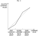
- the numbers of second image data belonging to the first luminance value group and the third luminance value group are less than a predetermined critical value, while the number of second image data belonging to the second luminance value group is greater than the predetermined critical value.
- the predetermined critical value may be, but not limited to, 1/3 a total number of the second image data input to the luminance adjustment unit 300, or 1/n a total number of the second image data input to the luminance adjustment unit 300, where n is the number of different luminance value groups present in the data set.
- a variation rate of adjusted luminance values (Y') with respect to the input luminance values (Y) is adjusted to be greater than 1 in the second luminance value group section, while variation rates of adjusted luminance values (Y') with respect to the input luminance values (Y) are adjusted to be less than 1 in the first luminance value group section and the third luminance value group section.
- the luminance adjustment unit 300 may generally readjust the respective adjusted luminance values.
- the luminance adjustment unit 300 may further include a luminance level shift unit (not shown).
- the luminance level shift unit may receive a consumption current limit signal indicating a consumption current limit ratio and may reduce all of the luminance values according to the consumption current limit ratio.
- Targets to be down shifted may be adjusted luminance values.
- the received consumption current limit ratio is 50%
- all of the adjusted luminance values (Y') are reduced to 50%.
- the variation rate of adjusted luminance values (Y') with respect to the input luminance values (Y) is adjusted to be greater than 1
- a greater luminance difference between gray scales can be ensured than with original data, thereby enhancing visibility.
- the second image conversion unit 500 receives adjusted or readjusted luminance values (Y' or Y") from the luminance adjustment unit 300 or chrominance values (G13, G23) output from the first image conversion unit 100, generates R'G1'/B'G2' data as third image data, and outputs the same to the display unit 600.
- the R'G1'/B'G2' data are inversely converted data.
- R', G1', B' and G2' may be referred to as inversely converted R' data, inversely converted G1' data, inversely converted B' data and inversely converted G2' data, respectively.
- FIG. 14 is a block diagram of an example structure of a second image conversion unit shown in FIG. 1 .
- the second image conversion unit 500 may include a variable inverse conversion unit 510, and an inverse operation unit 520.
- the variable inverse conversion unit 510 receives Y'CbCr or Y"CbCr data from the luminance adjustment unit and inversely converts the same into R'G4B' data.
- the inverse operation unit 520 receives the R'G4B' data from the variable inverse conversion unit 510, receives G13 and G23 data from the second operation unit 130 of the first image conversion unit 100, and performs operations of G1' data and G2' data using the data.
- the inverse operation unit 520 generates third image data, that is, R'G1' data and B'G2' data, using the computed data, and outputs the generated R'G1' data and B'G2' data to the display unit 600.
- the display unit 600 displays an adjusted image frame using the third image data R'G1'/B'G2' data.
- pixels are arranged in a pen tile configuration, and RG1/BG2 input data are converted into R'G1'/R'G2' data to then be input to the display unit.
- the above described concepts may be applied to a real type pixel arrangement in which R, G, B pixels are alternately arranged in a stripe or dot pattern.
- the converting of RG1/BG2 into R/G3/B and the converting of R/G4/B into R'G1'/B'G2' in the above-described embodiments may be skipped.
- FIG. 15 is a block diagram of a display apparatus according to another embodiment.
- the display apparatus 2000 is different from the display apparatus according to the previous embodiment in that it further includes a chroma correction unit 400.
- the chroma correction unit 400 may correct chrominance values of the second image data. As a luminance adjustment unit 300 adjusts luminance values of the second image data, brightness of an original image may be varied. The chroma correction unit 400 may correct chromas of the image increasing or decreasing according to the luminance value adjustment by the luminance adjustment unit 300.
- a user may have a preference for a particular chroma and may demand viewing a desired image according to the preference chroma value.
- the chroma correction unit 400 may receive a user's preference chroma and may correct a chrominance value according to the received user's preference chroma.
- a sensitively enhanced image can be output by increasing or decreasing the chroma according to the changed luminance.
- enhanced visibility of the image can be provided by color adjustment.
- FIG. 16 is a flow chart illustrating a method for driving a display apparatus according to an embodiment.
- the method for driving a display apparatus may include converting a plurality of first image data forming an image frame into a plurality of second image data each including a luminance value (S10). Converting of the image frame, first image data, second image data and first image data is substantially the same as that shown in FIGS. 1 to 15 , and repeated explanations thereof will not be given.
- the respective luminance values of the second image data are adjusted based on the numbers of the second image data matched for the respective luminance value groups (S40).
- the adjusting of the respective luminance values of the second image data is substantially the same as that shown in FIGS. 1 to 15 , and repeated explanations thereof will not be given.
- R/G/B data are converted into Y/Cb/Cr data and processed, thereby preventing a color change. Therefore, visibility can be enhanced by increasing brightness of an image in a limited brightness level, and a chroma is increased or decreased according to the brightness change, thereby outputting a sensitively enhanced image and providing for enhanced visibility of the image by color adjustment.
Landscapes
- Engineering & Computer Science (AREA)
- Multimedia (AREA)
- Signal Processing (AREA)
- Physics & Mathematics (AREA)
- General Physics & Mathematics (AREA)
- Theoretical Computer Science (AREA)
- Computer Hardware Design (AREA)
- Control Of Indicators Other Than Cathode Ray Tubes (AREA)
- Transforming Electric Information Into Light Information (AREA)
- Controls And Circuits For Display Device (AREA)
- Testing, Inspecting, Measuring Of Stereoscopic Televisions And Televisions (AREA)
Abstract
Description
- The disclosed technology relates to a display apparatus and a method for driving the same. The display apparatus, which adjusts a luminance value of an image, and a method for driving the same are disclosed.
- In general, there are numerous color producing methods for an image display field. For example, three primary colors of red, green and blue may be mixed with one another and then displayed on a display apparatus using R (Red), G (Green) and B (Blue) signals. In addition, as another representative color space used in the printing field, a CMY color model may be used. According to the CMY color model, colors of cyan, magenta and yellow may be used on a display apparatus using C (Cyan), M (Magenta) and Y (Yellow) signals. Further, using a Y (Luminance), Cb (B-color difference) and Cr (R-color difference) color model, images may be displayed using gamma-converted luminance and chrominance component signals. Additionally, a color model using H (Hue), S (Saturation) and V (Value), which effectively portrays human features , is widely used in extracting characteristic vectors of an image.
- In order to achieve a low power display in the signal conversion process, various studies are being conducted, including a method of limiting the maximum luminance or hue.
- One inventive aspect is a display apparatus. The display apparatus includes a first image conversion unit configured to convert first image data forming an image frame into second image data including a plurality of luminance values, and a luminance analysis unit configured to determine quantities of luminance values of the second image data, and configured to determine a distribution of the luminance values. The distribution includes luminance value groups each including one or more luminance values, and the display apparatus also includes a luminance adjustment unit configured to adjust the respective luminance values of the second image data based on the distribution of luminance values of the second image data.
- The luminance value groups may include a first luminance value group and a second luminance value group, and the maximum luminance value of the first luminance value group is less than the minimum luminance value of the second luminance value group.
- The luminance adjustment unit may be configured to adjust the respective luminance values of the second image data based on the number of the second image data belonging to the first luminance value group and the second luminance value group, and wherein the respective luminance values of the second image data belonging to the first luminance value group are adjusted according to the same first criteria, and the respective luminance values of the second image data belonging to the second luminance value group are adjusted according to the same second criteria, different from the first criteria.
- In other words, the first criteria is used for all luminance values in the first luminance group, the second criteria is used for all luminance values in the second luminance group, the third criteria is used for all luminance values in the third luminance group.
- Preferably, if the number of the second image data belonging to the first luminance value group exceeds a threshold value, the luminance adjustment unit adjusts a variation rate of neighboring adjusted luminance values with respect to the corresponding neighboring luminance values of each of the luminance value groups to be greater than 1, and if the number of the second image data belonging to the first luminance value group is lower than the threshold value, the luminance adjustment unit adjusts the variation rate to be lower than 1.
- Preferably, the threshold value is 1/2 a total number of the second image data belonging to the first and second luminance value groups. In general, the threshold value is 1/n a total number of the second image data belonging to all of the different "n" luminance value groups present in the embodiment.
- The plurality of luminance value groups may include a first luminance value group, a second luminance value group, and a third luminance value group, wherein the maximum luminance value of the first luminance value group is less than the minimum luminance value of the second luminance value group, and wherein the maximum luminance value of the second luminance value group is less than the minimum luminance value of the third luminance value group. The luminance adjustment unit may be configured to adjust the respective luminance values of the second image data based on the number of the second image data belonging to the first luminance value group, the second luminance value group and the third luminance value group, wherein the respective luminance values of the second image data belonging to the first luminance value group are adjusted according to the same criteria, i.e. a first criteria common for the first luminance value group data, the respective luminance values of the second image data belonging to the second luminance value group are adjusted according to the same criteria, i.e. a second criteria common for the second luminance value group data and different from the first criteria and wherein the respective luminance values of the second image data belonging to the third luminance value group are adjusted according to the same criteria, i.e. a third criteria common for the third luminance value group data and different than the first and second criteria.
- In other words, the first criteria is used for all luminance values in the first luminance group, the second criteria is used for all luminance values in the second luminance group, the third criteria is used for all luminance values in the third luminance group.
- If the number of the second image data belonging to the first luminance value group exceeds a threshold value, the luminance adjustment unit adjusts a variation rate of adjusted luminance value with respect to the luminance values of each of the luminance value groups to be greater than 1, and if the number of the second image data belonging to the first luminance value group is lower than the threshold value, the luminance adjustment unit adjusts the variation rate to be lower than 1.
- The threshold value may 1/3 a total number of the second image data belonging to the first, second and third luminance value groups, or 1/n, where "n" is the number of different luminance value groups.
- A luminance level shift unit may be provided that is configured to shift levels of the luminance values according to a ratio. The luminance level shift unit may be configured to receive a consumption current limit ratio and shifts levels of the luminance values according to the consumption current limit ratio.
- The first image data may include first color data, second color data, and third color data, and the plurality of second image data include a first color chrominance value and a third color chrominance value.
- The first image data may include first color data, second color first data, second color second data, and third color data, and the first image conversion unit comprises a first operation unit configured to convert an average of the second color first data and the second color second data into second color third data; a second operation unit configured to perform operations of a first difference value between the second color first data and the second color third data, and a second difference value between the second color second data and the second color third data; and a variable conversion unit configured to convert the first color data, the second color third data, and the third color data into the second image data including the luminance values, the first color chrominance value, and the third color chrominance value.
- The display apparatus may further comprise a second image conversion unit configure to convert the second image data including the adjusted luminance values into third image data; and a display unit configured to display the image frame using the third image data, wherein the third image data includes inversely converted first color data, inversely converted second color first data, inversely converted second color second data, and inversely converted third color data.
- The second image conversion unit may comprise a variable inverse conversion unit configured to inversely convert the adjusted luminance values, the first color chrominance value and the third color chrominance value into the inversely converted first color data, the inversely converted second color data and the inversely converted third color data; and an inverse operation unit configured to add the first difference value to the inversely converted second color data to generate the inversely converted second color first data, and adds the second difference value to the inversely converted second color data to generate the inversely converted second color second data.
- The first color may be red, the second color is green, and the third color is blue.
- The display apparatus may further comprise a chroma correction unit configured to correct chrominance values of the second image data. The chroma correction unit may be configured to correct chrominance values of the second image data according to the adjusted luminance values by the luminance adjustment unit. The chroma correction unit may be configured to correct chrominance values of the second image data according to the user's preference chroma.
- Another inventive aspect is a display apparatus. The display apparatus includes a luminance analysis unit configured to determine quantities of luminance values of image data forming an image frame and having respective luminance values, and configured to determine a distribution of the luminance values. The distribution includes luminance value groups each including the respective luminance values, and the display apparatus also includes a luminance adjustment unit configured to adjust the respective luminance values of the image data based on the distribution of luminance values of the image data.
- The luminance value groups may include a first luminance value group, a second luminance value group, and a third luminance value group, and wherein the maximum luminance value of the first luminance value group is less than the minimum luminance value of the second luminance value group, and the maximum luminance value of the second luminance value group is less than the minimum luminance value of the second luminance value group.
- The luminance adjustment unit may be configured to adjust the respective luminance values of the second image data based on the number of the second image data belonging to the first luminance value group, the second luminance value group and the third luminance value group, and wherein the respective luminance values of the image data belonging to the first luminance value group are adjusted according to the same criteria, the respective luminance values of the image data belonging to the second luminance value group are adjusted according to the same criteria, and the respective luminance values of the image data belonging to the third luminance value group are adjusted according to the same criteria.
- If the number of the image data belonging to each of the luminance value groups exceeds a threshold value, the luminance adjustment unit adjusts a variation rate of adjusted luminance value with respect to the luminance values of each of the luminance value groups to be greater than 1, and if the number of the image data belonging to each of the luminance value groups is less than the threshold value, the luminance adjustment unit adjusts the variation rate to be less than 1, and the critical value 1/3 a total number of the second image data belonging to the first, second and third luminance value groups.
- The luminance adjustment unit may further comprise a luminance level shift unit configured to shift levels of the luminance values according to a ratio, wherein the luminance level shift unit is configured to receive a consumption current limit ratio and shifts levels of the luminance values according to the consumption current limit ratio.
- Another inventive aspect is a display apparatus. The display apparatus includes a first operation unit configured to receive an average of second color first data and second color second data of first image data and to convert the average into second color third data. The first image data includes first color data, second color first data, second color second data and third color data. The display apparatus also includes a second operation unit configured to determine a first difference value between the second color first data and the second color third data, and a second difference value between the second color second data and the second color third data, and a variable conversion unit configured to convert the first color data, the second color third data, and the third color data into the second image data including the luminance values, the first color chrominance value, and the third color chrominance value.
- Another inventive aspect is a method of driving a display apparatus. The method includes converting a plurality of first image data forming an image frame into a plurality of second image data each including a luminance value, determining quantities of the second image data for the respective luminance values, determining a distribution of the luminance values, where the distribution includes luminance value groups each including one or more luminance values, and adjusting the respective luminance values of the second image data based on the distribution of luminance values of the second image data.
- The plurality of luminance value groups may include a first luminance value group and a second luminance value group, and the maximum luminance value of the first luminance value group is less than the minimum luminance value of the second luminance value group. Adjusting of the respective luminance values of the second image data may comprise adjusting the respective luminance values of the second image data based on the number of the second image data belonging to the first luminance value group, the second luminance value group and the third luminance value group, and wherein the respective luminance values of the second image data belonging to the first luminance value group are adjusted according to the same criteria, the respective luminance values of the second image data belonging to the second luminance value group are adjusted according to the same criteria, and the respective luminance values of the second image data belonging to the third luminance value group are adjusted according to the same criteria.
- The adjusting of the respective luminance values of the second image data may comprise adjusting a variation rate of adjusted luminance value with respect to the luminance values of each of the luminance value groups to be greater than 1 if the number of the second image data belonging to the first luminance value group exceeds a threshold value, and adjusting the variation rate to be less than 1 if the number of the second image data belonging to the first luminance value group is less than the threshold value, and wherein the critical value is 1/3 a total number of the second image data belonging to the first, second and third luminance value groups, or 1/n where "n" is the number of different luminance value groups.
- The adjusting the respective luminance values of the second image data may comprise shifting levels of the respective luminance values according to a ratio, and the shifting of the levels of the respective luminance values comprises receiving a consumption current limit ratio and shifting levels of the luminance values according to the consumption current limit ratio.
- The first image data may include first color data, second color first data, second color second data and third color data, and wherein the converting the first image data comprises converting an average of the second color first data and the second color second data into second color third data; performing determining a first difference between the second color first data and the second color third data, and a second difference value between the second color second data and the second color third data; and converting the first color data, the second color third data, and the third color data into the second image data including the luminance values, the first color chrominance value, and the third color chrominance value.
- The method may further comprise converting the second image data including the adjusted luminance values into third image data including inversely converted first color data, inversely converted second color first data, inversely converted second color second data, and inversely converted third color data, wherein converting of the second image data comprises inversely converting the adjusted luminance values, the first color chrominance value, and the third color chrominance value into the inversely converted first color data, the inversely converted second color data, and the inversely converted third color data; adding the first difference value to the inversely converted second color data to generate the inversely converted second color first data; and adding the second difference value to the inversely converted second color data to generate the inversely converted second color second data.
- The above and other features and advantages are described in detail according to certain embodiments with reference to the attached drawings in which:
-
FIG. 1 is a block diagram of a display apparatus according to an embodiment; -
FIG. 2 is a plan view schematically illustrating a display unit according to an embodiment; -
FIG. 3 is a plan view schematically illustrating an image frame according to an embodiment; -
FIG. 4 is a detailed block diagram illustrating an example structure of a first image conversion unit shown inFIG. 1 ; -
FIG. 5 is a graph illustrating a relationship between luminance values and numbers of second image data for the respective luminance values; -
FIG. 6 is a graph illustrating a relationship between luminance value groups and numbers of second image data for the respective luminance value groups; -
FIG. 7 is a graph illustrating a relationship between original luminance values of second image data and adjusted luminance values; -
FIG. 8 is a graph illustrating a relationship between luminance value groups and numbers of second image data for the respective luminance value groups; -
FIG. 9 is a graph illustrating a relationship between original luminance values of second image data and adjusted luminance values; -
FIG. 10 is a graph illustrating a relationship between luminance value groups and numbers of second image data for the respective luminance value groups; -
FIG. 11 is a graph illustrating a relationship between original luminance values of second image data and adjusted luminance values; -
FIG. 12 is a graph illustrating a relationship between luminance value groups and numbers of second image data for the respective luminance value groups; -
FIG. 13 is a graph illustrating a relationship between original luminance values of second image data and adjusted luminance values; -
FIG. 14 is a block diagram of an example structure of a second image conversion unit shown inFIG. 1 ; -
FIG. 15 is a block diagram of a display apparatus according to another embodiment of the present invention; and -
FIG. 16 is a flow chart illustrating a method for driving a display apparatus according to an embodiment of the present invention. - Certain aspects and features of systems and methods may be understood more readily by reference to the following detailed description and the accompanying drawings. The present invention may, however, be embodied in many different forms and should not be construed as being limited to the embodiments set forth herein. Rather, these embodiments are provided so that this disclosure will be thorough and complete. In some embodiments, well-known structures and devices may not be shown in order not to obscure the description with unnecessary detail. Like numbers generally refer to like elements throughout. In the drawings, the thickness of layers and regions may be exaggerated for clarity.
- It will be understood that when an element or layer is referred to as being "on," or "connected to" another element or layer, it can be directly on or connected to the other element or layer or intervening elements or layers may be present. In contrast, when an element is referred to as being "directly on" or "directly connected to" another element or layer, there are no intervening elements or layers present. As used herein, the term "and/or" includes any and all combinations of one or more of the associated listed items.
- Spatially relative terms, such as "below," "beneath," "lower," "above," "upper," and the like, may be used herein for ease of description to describe one element or feature's relationship to another element(s) or feature(s) as illustrated in the figures. It will be understood that the spatially relative terms are intended to encompass different orientations of the device in use or operation in addition to the orientation depicted in the figures.
- Embodiments described herein will be described referring to plan views and/or cross-sectional views by way of ideal schematic views of the invention. Accordingly, the exemplary views may be modified depending on manufacturing technologies and/or tolerances. Therefore, the embodiments are not limited to those shown in the views, but include modifications in configurations formed on the basis of manufacturing processes. Therefore, regions exemplified in figures have schematic properties and shapes of regions shown in figures exemplify specific shapes of regions of elements.
- A display apparatus according to some embodiments includes an apparatus for displaying picture images, and examples thereof may include a liquid crystal display (LCD), an electrophoretic display (EPD), an organic light emitting diode (OLED), an LED, an organic electro luminescent (EL) display, a field emission display (FED), a surface-conduction electron-emitter display (SED), a plasma display panel (PDP), and a cathode ray tube (CRT) display apparatus. Hereinafter, embodiments are described in further detail with reference to the accompanying drawings.
-
FIG. 1 is a block diagram of a display apparatus according to an embodiment. Referring toFIG. 1 , thedisplay apparatus 1000 includes a firstimage conversion unit 100, aluminance analysis unit 200 and aluminance adjustment unit 300. In addition, thedisplay apparatus 1000 may further include a secondimage conversion unit 500 and adisplay unit 600. -
FIG. 2 is a plan view schematically illustrating a display unit according to an embodiment. Referring toFIG. 2 , thedisplay unit 10 includes a plurality ofpixels pixels - The plurality of
pixels pixels first color pixel 11,second color pixels third color pixel 12. Here, thefirst color pixel 11 is a red (R) pixel, thesecond color pixels third color pixel 12 is a blue (B) pixel. - The RGB pixels may be alternately arranged. In some embodiments, the RGB pixels may be arranged in a stripe or dot pattern alternately arranged in a column-wise or row-wise direction.
- In some other embodiments, as shown in
FIG. 2 , pixels may be arranged in a pen tile configuration. In the embodiment shown inFIG. 2 , numbers of R pixels and B pixels are equal to each other, while the number of G pixels is two times the number of the R pixels or the B pixels. R pixels and B pixels are alternately arranged in a jth column, and only G pixels are arranged in a (j+1)th column adjacent to the jth column. Meanwhile, every other G pixels are arranged in an ith row, and R and B pixels are arranged between the G pixels. The R and B pixels are also alternately arranged in the column-wise direction. - The image data that is generally used may include R/G/B data. Here, the R data, G data and B data exist in a ratio of 1:1:1. However, since a ratio of R pixels: G pixels: B pixels is 1:2:1 in the pixel arrangement shown in
FIG. 2 , it is difficult to drive the display unit using the general R/G/B data. Therefore, the R/G/B data may be converted into RG/BG data using a panel driver circuit. The panel driver circuit may be provided outside the display apparatus or may be incorporated into the display apparatus. In this embodiment, it is assumed that the data input to the display apparatus is RG1/BG2 data suitable to the pixel arrangement. Here, G1 refers to green first data and G2 green second data. The original input image data may be RG1/BG2 data, or R/G/B data converted from RG1/BG2 using an external panel driver circuit. - Referring back to
FIG. 1 , as described above, the firstimage conversion unit 100 receives RG1/BG2 data as first image data. Since thedisplay unit 10 includes a plurality of RG1/BG2 pixels, the RG1/BG2 data also include a plurality of data. The plurality of RG1/BG2 data may form frames 50, 51 and 52 for one image, as shown inFIG. 3 . The one image frames 50, 51 and 52 include all or part of one frame image or still image. As shown inFIG. 3 , the one image frames 50, 51 and 52 may be defined as the entire screen (50) of thedisplay unit 10, or a partial screen (51, 52) forming a specific block. Here, the specific block may be a region of interest to be subjected to luminance conversion. In some embodiments, the specific block may be a different window frame within the entire screen. - The first
image conversion unit 100 converts the received plurality of RG1/BG2 data into image data including luminance values, which will be described in more detail with reference toFIG. 4. FIG. 4 is a detailed block diagram illustrating an example structure of a first image conversion unit shown inFIG. 1 . Referring toFIG. 4 , the firstimage conversion unit 100 may include afirst operation unit 110, avariable conversion unit 120, and asecond operation unit 130. - The
first operation unit 110 receives RG1/BG2 and converts the same into RG3B data. Here, G3 may be obtained using Equation 1:
- The
variable conversion unit 120 receives the RG3B data from thefirst operation unit 110 and converts the same into second image data. The second image data may include luminance values and chrominance values. In some embodiments, one luminance value (Y) and two chrominance values may be converted from one of the first image data. The chrominance values may include a blue chrominance value (Cb) and a red chrominance value (Cr). - The
second operation unit 130 receives the G3 data from thefirst operation unit 110 and outputs a difference value G13 between the G3 data and G1 data and a difference value G23 between the G3 data and G2 data. The difference value G13 between the G3 data and G1 data and the difference value G23 between the G3 data and G2 data can be computed using Equations 2 and 3:

- The G13 and G23 obtained by the
second operation unit 130 may be input to the secondimage conversion unit 500 to be described later. - Referring back to
FIG. 1 , YCbCr data (or Y values of YCbCr data) output from the firstimage conversion unit 100 is input to theluminance analysis unit 200. Theluminance analysis unit 200 sums numbers of the second image data for luminance levels and matches the same to the respective luminance levels. Accordingly, theluminance analysis unit 200 determines a distribution of luminance levels. First, assuming that the YCbCr data output from the firstimage conversion unit 100 is obtained by converting RG1/BG2 data forming frames for an image, the numbers of all of the YCbCr data input to theluminance analysis unit 200 can be computed for the respective luminance levels. The numbers of all of the YCbCr data for the respective luminance levels can be computed as the number of target YCbCr data having the same Y value. As illustrated inFIG. 5 , the computed numbers are matched to the respective luminance values. - Meanwhile, the numbers of luminance values may be counted as natural numbers, which may be discrete numbers. In addition, the luminance values may also be discrete numbers if they are based on digital input values. In this case, a graph illustrating a discontinuous distribution may be obtained by matching the counted numbers to the luminance values. While
FIG. 5 illustrates a continuous curve for a better understanding, a discontinuous graph may be formed in practice, which may also apply to the following graphs. - In some other embodiments, a plurality of luminance values may be classified into two or more luminance value groups of the distribution. Each of the two or more luminance value groups may include one or more luminance values. In some embodiments, each of the two or more luminance value groups may include continuous luminance values or two or more adjacent luminance values.
- For example, as shown in the distributions of
FIGS. 6 and8 , the plurality of luminance value groups may include a first luminance value group and a second luminance value group. Each of the first luminance value group and the second luminance value group may include one or more luminance values. In an exemplary embodiment, the minimum luminance value of the second luminance value group may be greater than the maximum luminance value of the first luminance value group. - In some embodiments, if a section between the minimum and maximum values of the luminance values is an entire luminance value section, the minimum value of the luminance values may be the minimum luminance value of the first luminance value group, and the maximum value of the luminance values may be the maximum luminance value of the second luminance value group. In addition, a boundary between the first luminance value group and the second luminance value group may be formed by dividing the entire luminance value section in a ratio of 1:1. However, the dividing of the luminance value groups is not limited to the illustrated example.
- When the luminance values of each luminance value group is 2 or greater, the numbers of the plurality of luminance values of the respective luminance value groups are matched to a total of the numbers.
- Referring back to
FIG. 1 , the numbers of second image data belonging to the respective luminance value group are input to theluminance adjustment unit 300. Theluminance adjustment unit 300 adjusts the luminance values of the second image data based on the input numbers of the second image data. - For example, as shown in
FIG. 6 , when the number of the second image data belonging to the first luminance value group exceeds the number of the second image data belonging to the second luminance value group, or the number of the second image data belonging to the first luminance value group exceeds a threshold value, e.g., 1/2 the number of second image data forming frames for an image, or 1/n the number of second image data forming frames for an image, where n is the number of different luminance value groups present in the data set, or when the luminance adjustment unit adjusts a variation rate of adjusted luminance value with respect to the luminance values of each of the luminance value groups to be greater than 1, and when the number of the second image data belonging to the first luminance value group is less than the threshold value (that is, when the number of the second luminance value group is less than 1/2 (or 1/n as defined above) of the number of second image data forming frames for an image), the respective luminance values can be adjusted by the method illustrated inFIG. 7 . -
FIG. 7 is a graph illustrating a relationship between original luminance values of second image data and adjusted luminance values. Referring toFIG. 7 , a variation rate of adjusted luminance values (Y') with respect to a variation rate of luminance values (Y) in a first luminance value group section is adjusted to be greater than a variation rate of adjusted luminance values (Y') with respect to a variation rate of luminance values (Y) in a second luminance value group section. - In detail, a slope in the graph for the adjusted luminance values in the first luminance value group section may be adjusted to be greater than 1. That is to say, a variation rate of adjusted luminance values (Y') with respect to the input luminance values (Y) is greater than 1 in the first luminance value group section. In other words, wherein a luminance value difference between two neighboring luminance values of the first luminance group prior to adjustment is equal to 1, after adjustment the difference between the two neighboring luminance values is larger than 1. On the other hand, a slope in the graph for the adjusted luminance values in the second luminance value group section may be adjusted to be lower than 1. That is to say, a variation rate of adjusted luminance values (Y') with respect to the input luminance values (Y) is lower than 1 in the second luminance value group section. In other words, wherein a luminance value difference between two neighboring luminance values of the second luminance group prior to adjustment is equal to 1, after adjustment the difference between the two neighboring luminance values is lower than 1. Meanwhile, the graph for the adjusted luminance values in a boundary between the first luminance value group section and the second luminance value group section may be a continuous graph. In addition, the minimum luminance value of the first luminance value group and the maximum luminance value of the second luminance value group may be equal to input luminance values.
- The luminance value adjustment increases a luminance value difference in the first luminance value group section in which luminance values are relatively low while decreasing a luminance value difference in the second luminance value group section in which luminance values are relatively high. Therefore, the second image data belonging to the first luminance value group, which includes a relatively large number of pixels, can be more distinctly distinguished than the second image data belonging to the second luminance value group. Further, even if the overall levels of luminance values are decreased, luminance values of more pixels can be easily divided, thereby enhancing visibility. This can be utilized in selectively enhancing visibility of a primary display image when the number of pixels belonging to a luminance value group is proportional to the significance of an image to be displayed.
- The variation rate of adjusted luminance values (Y') with respect to input luminance values (Y) in each luminance value group section may be adjusted according to criteria including the difference between numbers of image data for the respective luminance value groups, the improvement extent of visibility, adjustment or non-adjustment of the overall luminance values and adjustment scale. In an exemplary embodiment, a variation rate of adjusted luminance values (Y') with respect to input luminance values (Y) in the first luminance value group may be adjusted to approximately 1.1 or 1.2 or within the range of [1.1; 1.2], and a variation rate in the second luminance value group may be adjusted to approximately 0.9 or 0.8 or within the range of [0.9; 0.8], but not limited thereto.
-
FIG. 8 illustrates that the number of second image data belonging to the second luminance value group having relatively high luminance is larger than the number of second image data belonging to the first luminance value group having relatively low luminance.FIG. 9 illustrates that luminance values are adjusted by theluminance adjustment unit 300. Referring toFIGS. 8 and9 , since the number of second image data of the second luminance value group is larger than that of the first luminance value group, a variation rate of adjusted luminance values (Y') with respect to a variation rate of input luminance values (Y) in the first luminance value group section is adjusted to be greater than 1 and a variation rate of adjusted luminance values (Y') with respect to a variation rate of input luminance values (Y) in the second luminance value group section is adjusted to be less than 1. - As shown in
FIGS. 8 and9 , if a total of adjusted luminance values is increased or reduced compared to a total of input luminance values, power consumed may also be varied. To avoid this, theluminance adjustment unit 300 may proportionately readjust the respective adjusted luminance values so that the total of the adjusted luminance values is 100%. For example, if the total of adjusted luminance values is increased by 10% compared to the total of input luminance values, the adjusted luminance values can be readjusted by multiplying the respective adjusted luminance values by an inverse of 1.1. - In embodiments shown in
FIGS. 10 to 12 , distributions having a plurality of luminance value groups include a first luminance value group, a second luminance value group, and a third luminance value group. In some embodiments, if a section ranging between the minimum and maximum values of all luminance values is an entire luminance value section, the minimum value of all of the luminance values may be the minimum luminance value of the first luminance value group, and the maximum value of all of the luminance values may be the maximum luminance value of the third luminance value group. In addition, a boundary between the first luminance value group and the second luminance value group may be formed by dividing the entire luminance value section in a ratio of 1:2, and a boundary between the second luminance value group and the third luminance value group may be formed by dividing the entire luminance value section in a ratio of 2:1. However, the dividing of the luminance value groups is not limited to the illustrated example. - Referring to
FIG. 10 , the number of the second image data belonging to the first luminance value group and the number of the second image data belonging to the third luminance value group are greater than a threshold value, while the number of the second image data belonging to the second luminance value group is less than the threshold value. For example, the threshold value may be, but is not limited to, 1/3 a total number of the second image data input to theluminance adjustment unit 300. In general, the threshold value may be 1/n a total number of the second image data input to theluminance adjustment unit 300, where "n" is the number of different luminance value groups present in the embodiment. - As shown in
FIG. 11 , theluminance adjustment unit 300 adjusts luminance values of the first luminance value group and the third luminance value group, which exceeds the threshold value, thereby adjusting a variation rate of adjusted luminance values (Y') with respect to input luminance values (Y) to be greater than 1. In addition, for luminance values of the second luminance value group, which are less than the threshold value, a variation rate of adjusted luminance values (Y') with respect to input luminance values (Y) is adjusted to be greater than 1. - Meanwhile, the graph for the adjusted luminance values may be a continuous graph at a boundary between the first luminance value group section and the second luminance value group section and a boundary between the second luminance value group section and the third luminance value group section. In addition, the minimum luminance value of the first luminance value group and the maximum luminance value of the third luminance value group may be equal to input luminance values.
- As described above, the variation rate of adjusted luminance values (Y') with respect to input luminance values (Y) in each luminance value group section may be adjusted according to criteria including the difference between numbers of image data for the respective luminance value groups, the improvement extent of visibility, adjustment or non-adjustment of the overall luminance values and adjustment scale.
- The variation rates of adjusted luminance values (Y') with respect to input luminance values (Y) in the first luminance value group and the third luminance value group exceeding the critical value may be equal to each other irrespective of the excess extent of the respective luminance value groups. In some embodiments, the variation rate of either of the first luminance value group or the third luminance value group, whichever has more luminance values exceeding the critical value, may be adjusted to be greater than the other. In some other embodiments, 2 or more critical values may be assigned, thereby adjusting the variation rate adjustment extent differently according to whether the luminance values exceed the respective critical values.
- Referring to
FIG. 12 , in this embodiment, the numbers of second image data belonging to the first luminance value group and the third luminance value group are less than a predetermined critical value, while the number of second image data belonging to the second luminance value group is greater than the predetermined critical value. The predetermined critical value may be, but not limited to, 1/3 a total number of the second image data input to theluminance adjustment unit 300, or 1/n a total number of the second image data input to theluminance adjustment unit 300, where n is the number of different luminance value groups present in the data set. - Referring to
FIG. 13 , since the number of second image data belonging to the second luminance value group is greater than the threshold value, a variation rate of adjusted luminance values (Y') with respect to the input luminance values (Y) is adjusted to be greater than 1 in the second luminance value group section, while variation rates of adjusted luminance values (Y') with respect to the input luminance values (Y) are adjusted to be less than 1 in the first luminance value group section and the third luminance value group section. - Referring back to
FIG. 1 , theluminance adjustment unit 300 may generally readjust the respective adjusted luminance values. To this end, theluminance adjustment unit 300 may further include a luminance level shift unit (not shown). In an exemplary embodiment, the luminance level shift unit may receive a consumption current limit signal indicating a consumption current limit ratio and may reduce all of the luminance values according to the consumption current limit ratio. - Targets to be down shifted may be adjusted luminance values. Readjusted luminance values (Y") may be computed using Equation 4:

wherein Y' is an adjusted luminance value and B is a consumption current limit ratio. - For example, when the received consumption current limit ratio is 50%, all of the adjusted luminance values (Y') are reduced to 50%. Here, as described above, in the luminance value group section in which the variation rate of adjusted luminance values (Y') with respect to the input luminance values (Y) is adjusted to be greater than 1, even if the luminance values are reduced by 50%, a greater luminance difference between gray scales can be ensured than with original data, thereby enhancing visibility.
- The second
image conversion unit 500 receives adjusted or readjusted luminance values (Y' or Y") from theluminance adjustment unit 300 or chrominance values (G13, G23) output from the firstimage conversion unit 100, generates R'G1'/B'G2' data as third image data, and outputs the same to thedisplay unit 600. Here, the R'G1'/B'G2' data are inversely converted data. Thus, R', G1', B' and G2' may be referred to as inversely converted R' data, inversely converted G1' data, inversely converted B' data and inversely converted G2' data, respectively. -
FIG. 14 is a block diagram of an example structure of a second image conversion unit shown inFIG. 1 . Referring toFIG. 14 , the secondimage conversion unit 500 is described in more detail. The secondimage conversion unit 500 may include a variableinverse conversion unit 510, and aninverse operation unit 520. - The variable
inverse conversion unit 510 receives Y'CbCr or Y"CbCr data from the luminance adjustment unit and inversely converts the same into R'G4B' data. Theinverse operation unit 520 receives the R'G4B' data from the variableinverse conversion unit 510, receives G13 and G23 data from thesecond operation unit 130 of the firstimage conversion unit 100, and performs operations of G1' data and G2' data using the data. The G1' data and G2' data are computed using Equation 5:

- The
inverse operation unit 520 generates third image data, that is, R'G1' data and B'G2' data, using the computed data, and outputs the generated R'G1' data and B'G2' data to thedisplay unit 600. Thedisplay unit 600 displays an adjusted image frame using the third image data R'G1'/B'G2' data. - In the display apparatus of the above-described embodiments, pixels are arranged in a pen tile configuration, and RG1/BG2 input data are converted into R'G1'/R'G2' data to then be input to the display unit. However, the above described concepts may be applied to a real type pixel arrangement in which R, G, B pixels are alternately arranged in a stripe or dot pattern. In this case, the converting of RG1/BG2 into R/G3/B and the converting of R/G4/B into R'G1'/B'G2' in the above-described embodiments may be skipped.
-
FIG. 15 is a block diagram of a display apparatus according to another embodiment. Referring toFIG. 15 , thedisplay apparatus 2000 is different from the display apparatus according to the previous embodiment in that it further includes achroma correction unit 400. - The
chroma correction unit 400 may correct chrominance values of the second image data. As aluminance adjustment unit 300 adjusts luminance values of the second image data, brightness of an original image may be varied. Thechroma correction unit 400 may correct chromas of the image increasing or decreasing according to the luminance value adjustment by theluminance adjustment unit 300. - In addition, a user may have a preference for a particular chroma and may demand viewing a desired image according to the preference chroma value. The
chroma correction unit 400 may receive a user's preference chroma and may correct a chrominance value according to the received user's preference chroma. As described above, a sensitively enhanced image can be output by increasing or decreasing the chroma according to the changed luminance. In addition, enhanced visibility of the image can be provided by color adjustment. -
FIG. 16 is a flow chart illustrating a method for driving a display apparatus according to an embodiment. The method for driving a display apparatus may include converting a plurality of first image data forming an image frame into a plurality of second image data each including a luminance value (S10). Converting of the image frame, first image data, second image data and first image data is substantially the same as that shown inFIGS. 1 to 15 , and repeated explanations thereof will not be given. - Next, numbers of the second image data for the respective luminance values are counted (S20), and the counted numbers are summed and matched with a plurality of luminance value groups each including one or more luminance values (S30). The counting, summing and matching is substantially the same as that shown in
FIGS. 1 to 15 , and repeated explanations thereof will not be given. - Next, the respective luminance values of the second image data are adjusted based on the numbers of the second image data matched for the respective luminance value groups (S40). The adjusting of the respective luminance values of the second image data is substantially the same as that shown in
FIGS. 1 to 15 , and repeated explanations thereof will not be given. - In some inventive aspects, R/G/B data are converted into Y/Cb/Cr data and processed, thereby preventing a color change. Therefore, visibility can be enhanced by increasing brightness of an image in a limited brightness level, and a chroma is increased or decreased according to the brightness change, thereby outputting a sensitively enhanced image and providing for enhanced visibility of the image by color adjustment.
- While the various aspects have been particularly shown and described with reference to exemplary embodiments, it will be understood by those of ordinary skill in the art that various changes in form and details may be made therein without departing from the spirit and scope of the present invention. It is therefore understood that the present embodiments are to be considered in all respects as illustrative and not restrictive.
Claims (15)
- A display apparatus comprising:a first image conversion unit (100) configured to convert first image data forming an image frame into second image data including a plurality of luminance values;a luminance analysis unit (200) configured to determine quantities of luminance values of the second image data, and configured to determine a distribution of the luminance values, whereinthe distribution includes luminance value groups each including one or more different luminance values; anda luminance adjustment unit (300) configured to adjust the respective luminance values of the second image data based on the distribution of luminance values of the second image data.
- The display apparatus of claim 1, wherein the luminance value groups include a first luminance value group and a second luminance value group, and the maximum luminance value of the first luminance value group is less than the minimum luminance value of the second luminance value group.
- The display apparatus of claim 2, wherein the luminance adjustment unit (300) is configured to adjust the respective luminance values of the second image data based on the number of the second image data belonging to the first luminance value group and the second luminance value group, and wherein the respective luminance values of the second image data belonging to the first luminance value group are adjusted according to the same first criteria, and the respective luminance values of the second image data belonging to the second luminance value group are adjusted according to the same second criteria, different from the first criteria.
- The display apparatus of claim 3, wherein if the number of the second image data belonging to the first luminance value group exceeds a threshold value, the luminance adjustment unit (300) adjusts a variation rate of neighboring adjusted luminance values with respect to the corresponding neighboring luminance values of each of the luminance value groups to be greater than 1, and if the number of the second image data belonging to the first luminance value group is lower than the threshold value, the luminance adjustment unit (300) adjusts the variation rate to be lower than 1.
- The display apparatus of claim 4, wherein the threshold value is 1/2 a total number of the second image data belonging to the first and second luminance value groups.
- The display apparatus of one of the previous claims, further comprising a luminance level shift unit that is configured to shift levels of the luminance values according to a ratio.
- The display apparatus of claim 6, wherein the luminance level shift unit is configured to receive a consumption current limit ratio and shifts levels of the luminance values according to the consumption current limit ratio.
- The display apparatus of one of the previous claims, wherein the first image data include first color data, second color data, and third color data, and the plurality of second image data include a first color chrominance value and a third color chrominance value.
- The display apparatus of one of the previous claims 1 to 7, wherein the first image data includes first color data, second color first data, second color second data, and third color data, and the first image conversion unit (100) comprises:a first operation unit (110) configured to convert an average of the second color first data andthe second color second data into second color third data;a second operation unit (130) configured to perform operations of a first difference value between the second color first data and the second color third data, and a second difference value between the second color second data and the second color third data; anda variable conversion unit (120) configured to convert the first color data, the second color third data, and the third color data into the second image data including the luminance values, the first color chrominance value, and the third color chrominance value.
- The display apparatus of claim 9, further comprising:a second image conversion unit (500) configured to convert the second image data including the adjusted luminance values into third image data; anda display unit (600) configured to display the image frame using the third image data,wherein the third image data includes inversely converted first color data, inversely converted second color first data, inversely converted second color second data, and inversely converted third color data.
- The display apparatus of claim 10, wherein the second image conversion unit (500) comprises:a variable inverse conversion unit (510) configured to inversely convert the adjusted luminance values, the first color chrominance value and the third color chrominance value into the inversely converted first color data, the inversely converted second color data and the inversely converted third color data; andan inverse operation unit (520) configured to add the first difference value to the inversely converted second color data to generate the inversely converted second color first data, and adds the second difference value to the inversely converted second color data to generate the inversely converted second color second data.
- The display apparatus of one of the previous claims, further comprising a chroma correction unit (400) configured to correct chrominance values of the second image data, preferably according to the adjusted luminance values of the luminance adjustment unit (300).
- A method of driving a display apparatus, the method comprising:converting a plurality of first image data forming an image frame into a plurality of second image data each including a luminance value;determining quantities of the second image data for the respective luminance values;determining a distribution of the luminance values, wherein the distribution includes luminance value groups each including one or more luminance values; andadjusting the respective luminance values of the second image data based on the quantities of luminance values of the second image data.
- The method of claim 13, wherein the plurality of luminance value groups include a first luminance value group and a second luminance value group, and the maximum luminance value of the first luminance value group is lower than the minimum luminance value of the second luminance value group.
- The method of claim 14, wherein adjusting of the respective luminance values of the second image data comprises adjusting the respective luminance values of the second image data based on the number of the second image data belonging to the first luminance value group, the second luminance value group and the third luminance value group, and wherein the respective luminance values of the second image data belonging to the first luminance value group are adjusted according to the same criteria, the respective luminance values of the second image data belonging to the second luminance value group are adjusted according to the same criteria, and the respective luminance values of the second image data belonging to the third luminance value group are adjusted according to the same criteria.
Applications Claiming Priority (1)
| Application Number | Priority Date | Filing Date | Title |
|---|---|---|---|
| KR1020110077035A KR20130015179A (en) | 2011-08-02 | 2011-08-02 | Display apparatus and method for driving the same |
Publications (2)
| Publication Number | Publication Date |
|---|---|
| EP2555505A2 true EP2555505A2 (en) | 2013-02-06 |
| EP2555505A3 EP2555505A3 (en) | 2014-01-08 |
Family
ID=45656442
Family Applications (1)
| Application Number | Title | Priority Date | Filing Date |
|---|---|---|---|
| EP12156541.0A Withdrawn EP2555505A3 (en) | 2011-08-02 | 2012-02-22 | Display apparatus and method for driving the same |
Country Status (6)
| Country | Link |
|---|---|
| US (1) | US8817038B2 (en) |
| EP (1) | EP2555505A3 (en) |
| JP (1) | JP5995456B2 (en) |
| KR (1) | KR20130015179A (en) |
| CN (1) | CN102915721B (en) |
| TW (1) | TWI554992B (en) |
Cited By (1)
| Publication number | Priority date | Publication date | Assignee | Title |
|---|---|---|---|---|
| EP3185207A4 (en) * | 2014-08-22 | 2018-09-19 | Olympus Corporation | Image processing device, image processing method, and image processing program |
Families Citing this family (22)
| Publication number | Priority date | Publication date | Assignee | Title |
|---|---|---|---|---|
| JP2011205467A (en) * | 2010-03-26 | 2011-10-13 | Fuji Xerox Co Ltd | Color processing apparatus, and program |
| US9460497B2 (en) | 2012-09-21 | 2016-10-04 | Htc Corporation | Image enhancement methods and systems using the same |
| US20140285531A1 (en) * | 2013-03-19 | 2014-09-25 | Ericsson Television Inc. | System, method, and device for adjusting display luminance |
| CN104517587B (en) * | 2013-09-27 | 2017-11-24 | 联想(北京)有限公司 | A kind of screen display method and electronic equipment |
| CN103699347B (en) * | 2013-11-26 | 2017-04-12 | 敦泰科技有限公司 | Method for data transmission, processor and terminal |
| KR102196912B1 (en) * | 2014-02-13 | 2020-12-31 | 삼성디스플레이 주식회사 | display device and driving method thereof |
| JP2015170905A (en) * | 2014-03-05 | 2015-09-28 | ソニー株式会社 | Image processor, image processing method and image display device |
| KR102240043B1 (en) | 2014-07-17 | 2021-04-15 | 삼성디스플레이 주식회사 | Method of driving organic light emitting display device and organic light emitting display device for performing the same |
| EP2998977B1 (en) * | 2014-09-19 | 2018-07-04 | ABB Schweiz AG | A method for determining the operating status of a mv switching device of the electromagnetic type |
| JP6233424B2 (en) * | 2016-01-05 | 2017-11-22 | ソニー株式会社 | Imaging system and imaging method |
| KR102439245B1 (en) * | 2016-01-29 | 2022-09-01 | 삼성전자주식회사 | Electronic device and controlling method thereof |
| CN107741825A (en) * | 2016-03-31 | 2018-02-27 | 广东欧珀移动通信有限公司 | A kind of adjusting method of brightness, adjusting means and terminal and medium product |
| CN105959584B (en) * | 2016-04-29 | 2019-01-22 | 京东方科技集团股份有限公司 | A kind of image processing method, image processing apparatus and display device |
| CN106157869B (en) * | 2016-06-30 | 2019-11-05 | 京东方科技集团股份有限公司 | A kind of colour cast modification method, correcting device and display device showing image |
| US10067565B2 (en) * | 2016-09-29 | 2018-09-04 | Intel Corporation | Methods and apparatus for identifying potentially seizure-inducing virtual reality content |
| CN106898293B (en) * | 2017-02-16 | 2019-06-04 | 深圳市奥拓电子股份有限公司 | A kind of light-emitting diode display and its display brightness method of adjustment |
| KR102578536B1 (en) * | 2017-06-27 | 2023-09-13 | 가부시키가이샤 한도오따이 에네루기 켄큐쇼 | Display system and data processing methods |
| CN107452355B (en) * | 2017-08-09 | 2019-09-20 | 青岛海信电器股份有限公司 | A kind of method of adjustment and device of dynamic contrast |
| CN107808649B (en) * | 2017-10-10 | 2019-07-12 | 惠科股份有限公司 | The driving method and display device of display panel |
| KR102525560B1 (en) * | 2017-11-10 | 2023-04-26 | 삼성디스플레이 주식회사 | Image signal processing circuit, display device including the same and image signal processing method of the display device |
| KR102533411B1 (en) * | 2017-12-04 | 2023-05-18 | 삼성디스플레이 주식회사 | Image processor, display apparatus including the same, image processing method |
| BE1026562B1 (en) * | 2018-08-22 | 2020-03-26 | Drukkerij Voet Bvba | METHOD AND SYSTEM FOR INCREASING PRINT QUALITY |
Family Cites Families (19)
| Publication number | Priority date | Publication date | Assignee | Title |
|---|---|---|---|---|
| US5557358A (en) * | 1991-10-11 | 1996-09-17 | Minolta Camera Kabushiki Kaisha | Camera having an electronic viewfinder for displaying an object image under different photographic conditions |
| JP3709981B2 (en) * | 2001-05-31 | 2005-10-26 | 松下電器産業株式会社 | Gradation correction apparatus and method |
| US6980691B2 (en) * | 2001-07-05 | 2005-12-27 | Corel Corporation | Correction of “red-eye” effects in images |
| TWI220849B (en) | 2003-06-20 | 2004-09-01 | Weltrend Semiconductor Inc | Contrast enhancement method using region detection |
| KR100592385B1 (en) | 2003-11-17 | 2006-06-22 | 엘지.필립스 엘시디 주식회사 | Driving Method and Driving Device of Liquid Crystal Display |
| JP2006308631A (en) * | 2005-04-26 | 2006-11-09 | Seiko Epson Corp | Device, method and program for image display, and recording medium with image display program recorded |
| CA2611397C (en) * | 2005-07-11 | 2010-12-21 | Nippon Telegraph And Telephone Corporation | Video matching device, method, and program |
| JP4419933B2 (en) * | 2005-08-26 | 2010-02-24 | ソニー株式会社 | Image processing apparatus, image display apparatus, and image processing method |
| TWI309136B (en) * | 2005-12-01 | 2009-04-21 | Novatek Microelectronics Corp | Apparatus for adjusting specific color attributes and method thereof |
| JP4624248B2 (en) * | 2005-12-06 | 2011-02-02 | 富士フイルム株式会社 | Image processing apparatus, skin color adjustment method, and program |
| US8369646B2 (en) * | 2006-05-17 | 2013-02-05 | Sony Corporation | Image correction circuit, image correction method and image display |
| JP2008158399A (en) | 2006-12-26 | 2008-07-10 | Sony Corp | Device for reducing power consumption, self-luminous display device, electronic equipment, method for reducing power consumption and computer program |
| KR20080081644A (en) | 2007-03-06 | 2008-09-10 | 삼성에스디아이 주식회사 | Plasma display device and driving method thereof |
| JP2008311985A (en) * | 2007-06-15 | 2008-12-25 | Panasonic Corp | Phase adjustment apparatus and digital camera |
| US8285071B2 (en) | 2007-09-10 | 2012-10-09 | Himax Technologies Limited | Content-adaptive contrast improving method and apparatus for digital image |
| KR101393487B1 (en) | 2007-10-25 | 2014-05-14 | 삼성전자주식회사 | Display apparatus and method for image enhancement |
| JP4575963B2 (en) | 2008-02-14 | 2010-11-04 | 三菱電機株式会社 | Image processing device |
| JP4956488B2 (en) | 2008-06-10 | 2012-06-20 | 株式会社東芝 | Image processing apparatus and image display apparatus |
| JP2011141341A (en) * | 2010-01-05 | 2011-07-21 | Canon Inc | Image signal distribution apparatus and control method thereof, and program |
-
2011
- 2011-08-02 KR KR1020110077035A patent/KR20130015179A/en not_active Application Discontinuation
- 2011-12-07 US US13/313,914 patent/US8817038B2/en active Active
-
2012
- 2012-01-31 TW TW101102982A patent/TWI554992B/en active
- 2012-02-07 JP JP2012024427A patent/JP5995456B2/en active Active
- 2012-02-08 CN CN201210027706.8A patent/CN102915721B/en active Active
- 2012-02-22 EP EP12156541.0A patent/EP2555505A3/en not_active Withdrawn
Non-Patent Citations (1)
| Title |
|---|
| None |
Cited By (1)
| Publication number | Priority date | Publication date | Assignee | Title |
|---|---|---|---|---|
| EP3185207A4 (en) * | 2014-08-22 | 2018-09-19 | Olympus Corporation | Image processing device, image processing method, and image processing program |
Also Published As
| Publication number | Publication date |
|---|---|
| TW201308283A (en) | 2013-02-16 |
| CN102915721B (en) | 2016-12-14 |
| US8817038B2 (en) | 2014-08-26 |
| TWI554992B (en) | 2016-10-21 |
| KR20130015179A (en) | 2013-02-13 |
| JP5995456B2 (en) | 2016-09-21 |
| JP2013033202A (en) | 2013-02-14 |
| CN102915721A (en) | 2013-02-06 |
| EP2555505A3 (en) | 2014-01-08 |
| US20130033517A1 (en) | 2013-02-07 |
Similar Documents
| Publication | Publication Date | Title |
|---|---|---|
| US8817038B2 (en) | Display apparatus and method for driving the same | |
| US11056050B2 (en) | Display unit, image processing unit, and display method for improving image quality | |
| US9311841B2 (en) | Multi-primary colour display device | |
| US7808462B2 (en) | Display apparatus | |
| US9318075B2 (en) | Image driving using color-compensated image data that has been color-scheme converted | |
| KR101117980B1 (en) | Apparatus and method for driving liquid crystal display device | |
| WO2016150041A1 (en) | Pixel arrangement method, pixel rendering method and image display apparatus | |
| EP2135461B1 (en) | Input-signal transformation for rgbw displays | |
| US9251761B2 (en) | Gray-scale correction method for display device, and method of producing display device | |
| KR101720706B1 (en) | Display device | |
| US10290256B2 (en) | Field-sequential image display device and image display method | |
| TW201413693A (en) | Display, image processing unit, and display method | |
| US20140176620A1 (en) | Display unit, image processing device, display method, and electronic apparatus | |
| KR20070036720A (en) | Display image correcting device, image display device, and display image correcting method | |
| KR101137872B1 (en) | Apparatus and method for driving liquid crystal display device | |
| KR20080061772A (en) | Driving circuit for liquid crystal display device and method for driving the same | |
| JP2006267149A (en) | Display apparatus | |
| TW201415449A (en) | Image display unit, method of driving image display unit, signal generator, signal generation program, and signal generation method | |
| US20160035289A1 (en) | Image processing device and liquid crystal display device | |
| CN105684071B (en) | Signal generating apparatus, signal generate program, signal creating method and image display device | |
| US20150130856A1 (en) | Signal generation apparatus, signal generation program, signal generation method, and image display apparatus | |
| JP2007324665A (en) | Image correction apparatus and video display apparatus | |
| US10002573B2 (en) | Field sequential display device and drive method therefor | |
| KR102588297B1 (en) | Display apparatus and driving method thereof | |
| US20110249040A1 (en) | Color signal processing apparatus and color signal processing method |
Legal Events
| Date | Code | Title | Description |
|---|---|---|---|
| PUAI | Public reference made under article 153(3) epc to a published international application that has entered the european phase |
Free format text: ORIGINAL CODE: 0009012 |
|
| AK | Designated contracting states |
Kind code of ref document: A2 Designated state(s): AL AT BE BG CH CY CZ DE DK EE ES FI FR GB GR HR HU IE IS IT LI LT LU LV MC MK MT NL NO PL PT RO RS SE SI SK SM TR |
|
| AX | Request for extension of the european patent |
Extension state: BA ME |
|
| PUAL | Search report despatched |
Free format text: ORIGINAL CODE: 0009013 |
|
| AK | Designated contracting states |
Kind code of ref document: A3 Designated state(s): AL AT BE BG CH CY CZ DE DK EE ES FI FR GB GR HR HU IE IS IT LI LT LU LV MC MK MT NL NO PL PT RO RS SE SI SK SM TR |
|
| AX | Request for extension of the european patent |
Extension state: BA ME |
|
| RIC1 | Information provided on ipc code assigned before grant |
Ipc: G06T 5/00 20060101ALI20131202BHEP Ipc: H04N 1/60 20060101AFI20131202BHEP |
|
| 17P | Request for examination filed |
Effective date: 20140513 |
|
| RBV | Designated contracting states (corrected) |
Designated state(s): AL AT BE BG CH CY CZ DE DK EE ES FI FR GB GR HR HU IE IS IT LI LT LU LV MC MK MT NL NO PL PT RO RS SE SI SK SM TR |
|
| 17Q | First examination report despatched |
Effective date: 20150804 |
|
| RAP1 | Party data changed (applicant data changed or rights of an application transferred) |
Owner name: SAMSUNG DISPLAY CO., LTD. |
|
| GRAP | Despatch of communication of intention to grant a patent |
Free format text: ORIGINAL CODE: EPIDOSNIGR1 |
|
| INTG | Intention to grant announced |
Effective date: 20180103 |
|
| STAA | Information on the status of an ep patent application or granted ep patent |
Free format text: STATUS: THE APPLICATION IS DEEMED TO BE WITHDRAWN |
|
| 18D | Application deemed to be withdrawn |
Effective date: 20180515 |