EP2555463A2 - Kommunikationssystem mit verbesserten Kanalumschaltungsfunktionen basierend auf Modulationstreue und entsprechenden Methoden - Google Patents
Kommunikationssystem mit verbesserten Kanalumschaltungsfunktionen basierend auf Modulationstreue und entsprechenden Methoden Download PDFInfo
- Publication number
- EP2555463A2 EP2555463A2 EP12004971A EP12004971A EP2555463A2 EP 2555463 A2 EP2555463 A2 EP 2555463A2 EP 12004971 A EP12004971 A EP 12004971A EP 12004971 A EP12004971 A EP 12004971A EP 2555463 A2 EP2555463 A2 EP 2555463A2
- Authority
- EP
- European Patent Office
- Prior art keywords
- modulation
- base station
- fidelity
- channel
- wireless communications
- Prior art date
- Legal status (The legal status is an assumption and is not a legal conclusion. Google has not performed a legal analysis and makes no representation as to the accuracy of the status listed.)
- Granted
Links
Images


Classifications
-
- H—ELECTRICITY
- H04—ELECTRIC COMMUNICATION TECHNIQUE
- H04L—TRANSMISSION OF DIGITAL INFORMATION, e.g. TELEGRAPHIC COMMUNICATION
- H04L1/00—Arrangements for detecting or preventing errors in the information received
- H04L1/0001—Systems modifying transmission characteristics according to link quality, e.g. power backoff
- H04L1/0015—Systems modifying transmission characteristics according to link quality, e.g. power backoff characterised by the adaptation strategy
- H04L1/0019—Systems modifying transmission characteristics according to link quality, e.g. power backoff characterised by the adaptation strategy in which mode-switching is based on a statistical approach
-
- H—ELECTRICITY
- H04—ELECTRIC COMMUNICATION TECHNIQUE
- H04L—TRANSMISSION OF DIGITAL INFORMATION, e.g. TELEGRAPHIC COMMUNICATION
- H04L1/00—Arrangements for detecting or preventing errors in the information received
- H04L1/20—Arrangements for detecting or preventing errors in the information received using signal quality detector
- H04L1/206—Arrangements for detecting or preventing errors in the information received using signal quality detector for modulated signals
Definitions
- the present invention relates to the field of communications systems and, more particularly, to wireless communications systems and related methods.
- Wireless communications systems continue to grow in popularity and utilization.
- One such example is cellular networks, which continue to grow worldwide and add ever expanding coverage areas and enhanced cellular communications formats to increase bandwidth and data communication rates.
- trunked radio systems are used for such applications, as they allow for a given number of channels (i.e., communications frequencies) to be used to establish numerous talk groups.
- a control channel sends packets of data to enable talk group members to communicate with one another, regardless of frequency. This advantageously allows many people to conduct conversations over a relatively small number of frequencies.
- trunking systems are used to provide two-way communication for fire departments, police and other municipal services, who all share spectrum allocated to a city, county, or other entity.
- P25 A relatively new approach to trunked radio for governmental use is being developed as Project 25 (P25), or APCO-25, which encompasses a suite of standards for digital radio communications for use by federal, state/province and local public safety agencies in North America to enable them to communicate with other agencies and mutual aid response teams in emergencies.
- P25 takes advantage of the technological advances and expanded capabilities of digital radio.
- a wireless communications system includes at least one base station, and one or more communications devices configured to communicate with the base stations via a plurality of different wireless communications channels using a modulation standard wherein a received modulation differs from a transmitted modulation as measured by a modulation fidelity value.
- the communication devices are configured to determine respective modulation fidelity values associated with a current channel and an alternate channel based upon the modulation fidelity measured between the transmitted modulation and the received modulation for the current channel and the alternate channel, and to selectively switch between the current channel and the alternate channel based upon the determined modulation fidelity values.
- the system may advantageously allow for relatively quick assessment of alternate channel conditions, to thereby reduce channel switching delay.
- the communications device may be configured to determine the modulation fidelity values based upon an RMS frequency deviation error. Additionally, the communications device may be further configured to generate a bit error rate (BER) estimate for the current channel based upon the determined modulation fidelity values and a pre-determined calibration curve.
- BER bit error rate
- the base station and the communications device(s) are further configured to cooperate to determine positions of the best modulation fidelity (i.e., lowest RMS frequency deviation error) for the current channel and alternate channels at respective symbol sample points, and to determine the respective modulation fidelity values at the determined positions.
- the communications device may be further configured to determine the modulation fidelity based upon an average of measured frequency deviation errors at the determined positions.
- the communications device may be further configured to determine the modulation fidelity based upon error vector magnitudes (EVMs).
- EVMs error vector magnitudes
- a related communications device such as the one described briefly above, and a related communications method are also provided.
- the communications method includes causing at least one communications device to communicate with at least one base station via a current wireless communications channel from among a plurality of different wireless communications channels using a modulation standard, wherein a received modulation differs from a transmitted modulation as measured by a modulation fidelity value.
- the method further includes determining respective modulation fidelity values associated with the current channel and an alternate channel based upon a RMS frequency deviation error between the received modulation and the transmitted modulation for each channel, and selectively switching between the current channel and the alternate channel based upon the determined modulation fidelity values.
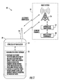
- FIG. 1 is a schematic block diagram of a wireless communications system in accordance with the invention.
- FIG. 2 is a flow diagram illustrating method aspects associated with the system of FIG. 1 .
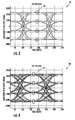
- FIG. 3 is an eye pattern diagram of received signal amplitude vs. time showing ideal modulation characteristics for sampled signals from the system of FIG. 1 .
- FIG. 4 is an eye pattern diagram similar to that of FIG. 3 further showing the effects of additional filtering in the receiver for sampled signals from the system of FIG. 1 .
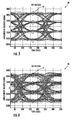
- FIGS. 5 and 6 are eye pattern diagrams similar to that of FIG. 4 further showing the effects of decreasing signal to interference ratios for sampled signals from the system of FIG. 1 .
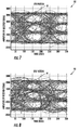
- FIGS. 7 and 8 are eye pattern diagrams similar to that of FIG. 4 further showing the effects of increased delay spread for sampled signals from the system of FIG. 1 .
- FIG. 9 is an eye diagram similar to that of FIG. 4 showing sampling positions for frequency error measurements in cases where symbol synchronization is known and unknown for sampled signals from the system of FIG. 1 .
- FIG. 10 is a graph of frequency modulation vs. time illustrating a demodulated FM signal over a measurement time interval for the system of FIG. 1 .
- FIG. 11 is an eye pattern diagram showing received signal amplitude vs. time for the demodulated FM signal of FIG. 10 over the measurement time interval for sampled signals from the system of FIG. 1 .
- FIG. 12 is a graph of signal interference ratio vs. modulation fidelity for the system of FIG. 1 .
- FIG. 13 is a graph of BER vs. modulation fidelity for the system of FIG. 1 .
- a wireless communications system 30 illustratively includes one or more base stations 31 and one or more communications devices 32.
- the base station 31 and communications device 32 are configured to communicate with one another via a plurality of different wireless communications channels using a modulation standard wherein the received modulation differs from the transmitted modulation as measured by a modulation fidelity value.
- a modulation standard that may be used by the system 30 is P25 (also known as APCO-25).
- P25 provides for digital radio communications by federal, state/province and local public safety agencies in North America to enable communications with other agencies and mutual aid response teams in emergencies.
- P25 modulation standard is made with reference to the P25 modulation standard, but it will be appreciated by the skilled artisan that the system and method aspects set forth herein may also be used with other wireless communication standards or protocols (e.g., the European TETRA protocol, cellular communications, etc.).
- pi/4 DQPSK is used as the downlink modulation standard, although here again other modulation standards may be used in different applications.
- the P25 Phase 2 standard is further described in the document entitled "Project 25 Phase 2 Two-Slot Time Division Multiple Access Physical Layer Protocol Specification", TIA-102.BBAB, July 2009.
- the communications device 32 includes one or more antennas 33, one or more wireless RF transceivers 34 coupled to the antenna, and a controller 35 coupled to the wireless RF transceiver.
- the wireless RF transceiver 34 may be configured to operate in accordance with one or more of the communications formats noted above, for example.
- the controller 35 may be implemented using a combination of hardware (e.g., processor, memories, signal processing circuitry, etc.) and software (e.g., a computer-readable medium having computer-executable instructions for performing the functions or operations described herein).
- the communications device 32 is based upon a multimode handheld radio, such as a P7300 dual-band multimode radio from the present assignee Harris Corporation, of Melbourne, Florida, although other types of communications devices may be used depending on the given communications format.
- a multimode handheld radio such as a P7300 dual-band multimode radio from the present assignee Harris Corporation, of Melbourne, Florida, although other types of communications devices may be used depending on the given communications format.
- the base station 31 illustratively includes one or more antennas (illustrated by a communications tower 36), a wireless RF transceiver(s), and a base station controller 38. It should be noted that, even though a communications tower is shown in FIG. 1 , the base station 31 may be a mobile device in some embodiments. Moreover, the various components of the base station 31 need not be geographically co-located in all instances. For example, some base station control operations may be performed remotely (e.g., at a network operating center, etc.).
- RSSI This provides a good indication as to which channel is broadcasting the strongest signal.
- a stronger signal does not always translate to more reliable data communication.
- the channel with the higher RSSI may be subject to a higher level of interference and/or multi-path than the other channel providing the "weaker" signal, and thus be less reliable than the other channel despite the higher RSSI.
- digital error rate is more indicative of reliability
- digital error rate calculations typically require a relatively long period to calculate, which for a large number of available channels may therefore require a long amount of time to measure, and thereby diminish data transmission time to undesirable levels.
- digital error rate determinations also typically require symbol synchronization information to be available, which is not always the case when measuring additional channels other than the current channel being used for communication.
- the system 30 and methods described herein estimate channel conditions for use in making roaming or channel switching decisions based upon an estimated modulation fidelity metric, which may advantageously be determined over a relatively short time duration. Since the modulation fidelity metric may be estimated over a relatively short duration of time, the delay between detecting that the current channel you are on is not yielding the best communication quality and switching to a better channel may therefore be minimized.
- Modulation fidelity estimation may be visually represented using eye pattern diagrams, which may conceptually be understood as an "oscilloscope view" of a repetitively sampled digital signal. As such, various eye pattern diagrams are referenced in the following description to illustrate the measurements and calculations being performed to determine modulation fidelity estimates.
- an eye pattern diagram 50 is shown for a relatively strong signal with a low frequency deviation error as measured at the symbol points (indicated by ovals 51).
- the eye pattern diagram 50 represents a close approximation of the ideal transmitted modulation, as there is little deviation (e.g., root mean square (RMS) error) from the expected frequency values at the symbol points.
- RMS root mean square
- the RMS frequency deviation error at the symbol points becomes more pronounced, as seen in the eye pattern diagram 50' of FIG. 4 at the symbol points (indicated by ovals 51').
- modulation fidelity values may be used to measure a difference between the received modulation (e.g., as shown in FIG. 4 ) from the transmitted modulation (e.g., as shown in FIG. 3 ).
- the symbol points occur at the position where the eye opening is the largest (i.e., at the center of the eye). This provides a convenient point for RMS frequency error measurement which will yield a modulation fidelity estimate, as symbol synchronization algorithms may be configured to find or lock on to this point in the signal transmission for signal synchronization, as this is where the RMS frequency error will be at its lowest. However, it should be noted that frequency error determination may be performed at other points in some embodiments. Determination of symbol positions will be discussed further below with reference to FIG. 9 .
- the effects of varying signal to interference (S/I) ratios can be seen on modulation fidelity.
- S/I ratio signal to interference
- the modulation fidelity worsens, which is reflected by the decreasing opening of the eye pattern.
- the width of the signal lines at the symbol points in FIG. 5 is narrower than at the symbol points in FIG. 6 (indicated by ovals 71), and thus that there is a better modulation fidelity with respect to the eye pattern diagram 60 than with respect to the eye pattern diagram 70.
- FIGS. 7 and 8 the effects of delay spread on eye patterns may be seen in FIGS. 7 and 8 . More particularly, a 50 ⁇ s delay spread is present in the eye pattern diagram 80 of FIG. 7 , and a 75 ⁇ s delay spread is present in the eye pattern diagram 90 of FIG. 8 . As may be seen, the higher delay spread (eye pattern diagram 90) results in a reduced eye opening, as shown by higher RMS errors at the symbol points (indicated by ovals 81 in FIG. 7 and ovals 91 in FIG. 8 ).
- the communications device 31 determines respective modulation fidelity values associated with a current channel and one or more alternate channels based upon an RMS frequency error between the received modulation and the transmitted modulation for each channel, at Block 42.
- the base station 31 may transmit signals with known FM signal characteristics (e.g., carrier frequency, symbol synchronization, etc.) which may be communicated to the communications device 32 via a control channel, from which the communications device may perform the error measurements and modulation fidelity estimates.
- the error measurements may be transmitted to the base station 31 (which may also include network computing/processing equipment) for performing the modulation fidelity determinations.
- the center point of the eye is accordingly known, and the frequency deviation error values (e.g., RMS error) occurring at this location (there are four in FIG. 9 , which are within the boundary 101) may be averaged to determine a modulation fidelity value.
- RMS error frequency deviation error values
- MF mean ⁇ abs ⁇ measured_FM - closest_symbol_FM , where MF is the modulation fidelity value, and error values are determined based upon the mean of absolute error values of a difference between measure FM values (measured_FM) and the expected ideal FM values (i.e., closest_symbol_FM which are known apriori based on the ideal characteristics of the transmitted modulation).
- MF mean ⁇ abs ⁇ measured_FM - closest_symbol_FM
- error values are determined based upon the mean of absolute error values of a difference between measure FM values (measured_FM) and the expected ideal FM values (i.e., closest_symbol_FM which are known apriori based on the ideal characteristics of the transmitted modulation).
- a median or other averaging value may be used in some applications.
- Another approach that may be used for determining modulation fidelity is based upon error vector magnitudes, as will be appreciated by those skilled in the art.
- modulation fidelity estimates may be determined on each decimated set of FM values for each of a plurality of sample positions, which are within the boundary 102.
- the final modulation fidelity may be considered as the minimum over each of the different sample positions (i.e., the minimum modulation fidelity value is used, which will occur at the symbol sample point where the RMS frequency deviation error is lowest).
- modulation fidelity may be determined over a relatively short time interval.
- demodulated FM values may be calculated over a 30 ms interval, for example, or less.
- the corresponding eye pattern diagram 110 is shown in FIG. 11 .
- the estimated receive modulation fidelity is approximately 150 Hz. Since received modulation fidelity may be estimated over a relatively short time duration, the system 30 may advantageously quickly assess adjacent channel conditions without acquiring symbol synchronization.
- the average modulation fidelity estimate may be determined over the selected time interval to reduce estimate variance in some applications, if desired.
- RSSI values may optionally be determined for the current and alternate channels, at Block 43.
- the communications device 32 may exclude from switching consideration those alternate channels that do not have a modulation fidelity value corresponding to a delivered audio quality (DAQ) threshold, at Block 44.
- DAQ delivered audio quality
- a DAQ threshold of 3.4 may be required in P25 applications, which corresponds to a modulation fidelity value of approximately 165 Hz or less. Accordingly, alternate channels having a modulation fidelity value of 165 Hz or less would be eligible for channel switching, while those with modulation fidelity values of greater than 165 Hz would not be considered for channel switching.
- the one with the highest RSSI value may then be selected to be switched to as the new current channel for communications between the base station 31 and the communications device 32, at Blocks 45-46.
- the highest RSSI value indicates the strongest signal and, typically, the base station 30 that is in closest proximity to the communications device 32.
- modulation fidelity may be used as the basis for channel switching without consideration of RSSI in some embodiments.
- a search for alternate channels may be triggered by the DAQ requirements for the current channel not being met, for example, or this may be done on a scheduled or periodic basis to continuously utilize the best available channel, depending upon the given implementation.
- the channel switching determination may be made by the base station 31 based upon modulation fidelity information provided by the communication device 32 (e.g., over the control channel). That is, the base station 32 may determine when channel switching is appropriate based upon the above-described criteria, and inform the communication device 32 of the given alternate channel that it is to switch to for subsequent data communications. However, in most implementations the communications device 31 will be configured to perform the alternate channel selection and switch over to the alternate channel as the new current channel for data communication. Moreover, it should also be noted that, as used herein, channel switching also refers to handoffs between different base stations. That is, an alternate channel may be provided by a different base station. In this regard, a plurality of base stations 31 may also communicate with one another (either via wired or wireless network connections) to coordinate roaming or handoff operations, as will be appreciated by those skilled in the art, based upon the modulation fidelity estimates from the various channels.
- FIGS. 12 and 13 another advantage of the modulation fidelity determination is that it may also be used to provide a BER estimate, but without the above-described drawbacks associated with traditional BER measurement and estimation. More particularly, in FIG. 12 a plot 120 of the relationship between the S/I ratio (SIR) and modulation fidelity is shown, and in FIG. 13 a plot 130 of the relationship between BER and modulation fidelity is shown. Accordingly, using such plots or corresponding look-up tables, when a given modulation fidelity value is estimated, a corresponding BER (or SIR) may advantageously be provided.
- Table 1 (below) includes select example look-up values for a P25 phase 1 system is provided below. Table 1 DAQ BER Modulation Fidelity [Hz] 4 ⁇ 1% ⁇ 135 3.4 ⁇ 2% ⁇ 165 3.0 ⁇ 2.6% ⁇ 185
Landscapes
- Engineering & Computer Science (AREA)
- Quality & Reliability (AREA)
- Computer Networks & Wireless Communication (AREA)
- Signal Processing (AREA)
- Physics & Mathematics (AREA)
- Probability & Statistics with Applications (AREA)
- Mobile Radio Communication Systems (AREA)
Applications Claiming Priority (1)
| Application Number | Priority Date | Filing Date | Title |
|---|---|---|---|
| US13/196,156 US8675480B2 (en) | 2011-08-02 | 2011-08-02 | Communications system providing enhanced channel switching features based upon modulation fidelity and related methods |
Publications (3)
| Publication Number | Publication Date |
|---|---|
| EP2555463A2 true EP2555463A2 (de) | 2013-02-06 |
| EP2555463A3 EP2555463A3 (de) | 2013-08-21 |
| EP2555463B1 EP2555463B1 (de) | 2014-10-08 |
Family
ID=46762780
Family Applications (1)
| Application Number | Title | Priority Date | Filing Date |
|---|---|---|---|
| EP12004971.3A Active EP2555463B1 (de) | 2011-08-02 | 2012-07-04 | Kommunikationssystem mit verbesserten Kanalumschaltungsfunktionen basierend auf Modulationstreue und entsprechende Methode |
Country Status (3)
| Country | Link |
|---|---|
| US (1) | US8675480B2 (de) |
| EP (1) | EP2555463B1 (de) |
| CA (1) | CA2782599C (de) |
Cited By (2)
| Publication number | Priority date | Publication date | Assignee | Title |
|---|---|---|---|---|
| WO2015088766A1 (en) * | 2013-12-13 | 2015-06-18 | Motorola Solutions, Inc. | Apparatus and method for enabling efficient handover of a receiving radio between radio frequency sites |
| CN111405540A (zh) * | 2020-04-08 | 2020-07-10 | 成都爱科特科技发展有限公司 | 一种用于紧急业务的信道分配方法 |
Families Citing this family (1)
| Publication number | Priority date | Publication date | Assignee | Title |
|---|---|---|---|---|
| CN113359084B (zh) * | 2021-05-08 | 2022-11-08 | 电子科技大学 | 一种卡口人员进出检测装置及方法 |
Citations (1)
| Publication number | Priority date | Publication date | Assignee | Title |
|---|---|---|---|---|
| US5553243A (en) | 1994-01-07 | 1996-09-03 | Ericsson Ge Mobile Communications Inc. | Method and apparatus for determining with high resolution the fidelity of information received on a communications channel |
Family Cites Families (29)
| Publication number | Priority date | Publication date | Assignee | Title |
|---|---|---|---|---|
| US5761240A (en) | 1996-02-06 | 1998-06-02 | Ericsson Inc. | Method and apparatus for determining an optical communications channel without loss of channel messages on a current communications channel |
| US6122503A (en) | 1996-10-08 | 2000-09-19 | At&T Wireless Services Inc | Method and apparatus for over-the-air programming of telecommunication services |
| US6148197A (en) | 1998-03-06 | 2000-11-14 | Sbc Technology Resources, Inc. | Intelligent roaming system with over the air programming |
| FI107979B (fi) | 1998-03-18 | 2001-10-31 | Nokia Mobile Phones Ltd | Järjestelmä ja laite matkaviestinverkon palvelujen hyödyntämiseksi |
| US7340251B1 (en) | 1999-03-30 | 2008-03-04 | Nokia Corporation | Scanning guard timer |
| US6859649B1 (en) | 1999-05-07 | 2005-02-22 | Cingular Wireless Ii, Inc. | Method for registering with a communication service |
| US7266371B1 (en) | 2000-02-22 | 2007-09-04 | Cingular Wireless Ii, Llc | Activation and remote modification of wireless services in a packet network context |
| US6597921B2 (en) | 2000-12-22 | 2003-07-22 | Sbc Properties, Lp | Method and system for protocol feature communication |
| US7706336B2 (en) | 2001-02-28 | 2010-04-27 | Motorola, Inc. | Mobile station architectures for circuit and packet modes and methods therefor |
| US7869826B2 (en) | 2001-06-15 | 2011-01-11 | Nokia Corporation | Method and apparatus for relating communications system identifications (SIDS) |
| US7835951B1 (en) | 2002-01-08 | 2010-11-16 | Brightpoint, Inc. | Distribution channel management for wireless devices and services |
| KR100879942B1 (ko) * | 2002-02-16 | 2009-01-22 | 엘지전자 주식회사 | 채널품질지시자 코딩을 위한 기저수열 생성방법 |
| US7359332B2 (en) * | 2002-03-13 | 2008-04-15 | Broadcom Corporation | Enhanced DOCSIS upstream channel changes |
| US6940843B2 (en) | 2003-02-14 | 2005-09-06 | Cisco Technology, Inc. | Selecting an access point according to a measure of received signal quality |
| US7580720B2 (en) | 2003-06-02 | 2009-08-25 | At&T Intellectual Property I, L.P. | Method and system for protocol feature communication |
| US7447176B2 (en) | 2003-06-03 | 2008-11-04 | Microsoft Corporation | Making roaming decisions based on association qualities between wireless devices and wireless access points |
| KR100962647B1 (ko) | 2003-10-27 | 2010-06-11 | 삼성전자주식회사 | 모바일 단말기의 이동성 지원 방법 및 그 시스템 |
| US7673036B1 (en) | 2003-12-05 | 2010-03-02 | At&T Mobility Ii Llc | Method and system for automated handling of service problems identified by a wireless device customer |
| WO2005081962A2 (en) | 2004-02-23 | 2005-09-09 | Roamware, Inc. | INTEGRATED CELLULAR VoIP FOR CALL REROUTING |
| WO2005086927A2 (en) | 2004-03-10 | 2005-09-22 | Roamware, Inc. | Inbound roamer multimedia messaging systems |
| US20050276252A1 (en) * | 2004-06-09 | 2005-12-15 | Sizeland Robert L | Medium access control for wireless networks |
| US7496362B2 (en) | 2004-07-28 | 2009-02-24 | Starhome Gmbh | Cellular network infrastructure as support for inbound roaming users |
| US7509125B2 (en) | 2005-03-18 | 2009-03-24 | Research In Motion Limited | Method for scanning wireless frequencies |
| US7522918B2 (en) * | 2005-07-08 | 2009-04-21 | Cta Communications, Inc. | Method and System for Evaluating Radio Coverage |
| US8466836B2 (en) * | 2005-08-31 | 2013-06-18 | CSR Technology Holdings Inc. | Fast fourier transform with down sampling based navigational satellite signal tracking |
| US8457219B2 (en) * | 2005-12-30 | 2013-06-04 | Ikanos Communications, Inc. | Self-protection against non-stationary disturbances |
| US8102756B2 (en) * | 2007-07-25 | 2012-01-24 | Qualcomm Incorporated | Method and apparatus for initial acquisition of signaling parameters for a wireless communications network |
| US8320858B2 (en) * | 2010-11-22 | 2012-11-27 | Motorola Solutions, Inc. | Apparatus for receiving multiple independent RF signals simultaneously and method thereof |
| US8543065B2 (en) * | 2010-11-30 | 2013-09-24 | Motorola Solutions, Inc. | Methods for using effective radiated transmit power of a base station at a wireless communication device to determine uplink transmission range and/or to adjust transmit power |
-
2011
- 2011-08-02 US US13/196,156 patent/US8675480B2/en active Active
-
2012
- 2012-07-04 CA CA2782599A patent/CA2782599C/en active Active
- 2012-07-04 EP EP12004971.3A patent/EP2555463B1/de active Active
Patent Citations (1)
| Publication number | Priority date | Publication date | Assignee | Title |
|---|---|---|---|---|
| US5553243A (en) | 1994-01-07 | 1996-09-03 | Ericsson Ge Mobile Communications Inc. | Method and apparatus for determining with high resolution the fidelity of information received on a communications channel |
Non-Patent Citations (1)
| Title |
|---|
| "Project 25 Phase 2 Two-Slot Time Division Multiple Access Physical Layer Protocol Specification", TIA-102.BBAB, July 2009 (2009-07-01) |
Cited By (6)
| Publication number | Priority date | Publication date | Assignee | Title |
|---|---|---|---|---|
| WO2015088766A1 (en) * | 2013-12-13 | 2015-06-18 | Motorola Solutions, Inc. | Apparatus and method for enabling efficient handover of a receiving radio between radio frequency sites |
| CN106105318A (zh) * | 2013-12-13 | 2016-11-09 | 摩托罗拉解决方案公司 | 用于实现接收无线电装置在射频站点之间的有效切换的装置和方法 |
| US9578578B2 (en) | 2013-12-13 | 2017-02-21 | Motorola Solutions, Inc. | Apparatus and method for enabling efficient handover of a receiving radio between radio frequency sites |
| AU2014364313B2 (en) * | 2013-12-13 | 2017-10-26 | Motorola Solutions, Inc. | Apparatus and method for enabling efficient handover of a receiving radio between radio frequency sites |
| CN106105318B (zh) * | 2013-12-13 | 2019-10-22 | 摩托罗拉解决方案公司 | 用于实现接收无线电装置在射频站点之间的有效切换的装置和方法 |
| CN111405540A (zh) * | 2020-04-08 | 2020-07-10 | 成都爱科特科技发展有限公司 | 一种用于紧急业务的信道分配方法 |
Also Published As
| Publication number | Publication date |
|---|---|
| EP2555463A3 (de) | 2013-08-21 |
| CA2782599C (en) | 2014-10-07 |
| CA2782599A1 (en) | 2013-02-02 |
| US8675480B2 (en) | 2014-03-18 |
| US20130033980A1 (en) | 2013-02-07 |
| EP2555463B1 (de) | 2014-10-08 |
Similar Documents
| Publication | Publication Date | Title |
|---|---|---|
| US10901067B2 (en) | Method and system for user equipment location determination on a wireless transmission system | |
| US9288783B2 (en) | Methods and apparatuses for reduction of interference during positioning measurements | |
| US20110039574A1 (en) | Apparatus and method for positioning a wireless user equipment | |
| EP2645797B1 (de) | Kommunikationsvorrichtung mit selektiver Spektrumszuweisung und dazugehörige Verfahren | |
| EP3878200B1 (de) | Messanpassung auf basis von kanalhärtung | |
| JPH08508865A (ja) | 異なる容量を有する2クラスのチャネルの使用 | |
| US20220231883A1 (en) | Methods and Apparatus for Measurement and UE Antenna Selection | |
| US8223692B2 (en) | Method and apparatus for determining a mobility of a mobile station in a wireless communication system | |
| WO2004032352A1 (en) | Improved link estimation in a communication system | |
| EP2555463B1 (de) | Kommunikationssystem mit verbesserten Kanalumschaltungsfunktionen basierend auf Modulationstreue und entsprechende Methode | |
| CN1274160C (zh) | 通信系统中的链路选择 | |
| US7263363B2 (en) | Method for mitigating intermodulation interference using channel power estimation and attenuation in a two-way radio communications system | |
| US9936463B2 (en) | Method for detecting a terminal by a base station, base station, and network entity | |
| Maiti et al. | Field experimental evaluation of mobile terminal velocity estimation based on Doppler spread detection for mobility control in heterogeneous cellular networks | |
| CN114286371B (zh) | 信号测量方法、装置及网络设备 | |
| EP1191719A2 (de) | Verfahren und Gerät zur Signalqualitätsbestimmung in einem Kommunikationssystem | |
| Akhila et al. | Handover in GSM networks | |
| Leung et al. | Interference estimation with noisy measurements in broadband wireless packet networks | |
| Budka et al. | A Bayesian method to improve mobile geolocation accuracy | |
| Maiti et al. | A field experimental evaluation of mobile terminal velocity estimation based on Doppler spread detection |
Legal Events
| Date | Code | Title | Description |
|---|---|---|---|
| PUAI | Public reference made under article 153(3) epc to a published international application that has entered the european phase |
Free format text: ORIGINAL CODE: 0009012 |
|
| 17P | Request for examination filed |
Effective date: 20120704 |
|
| AK | Designated contracting states |
Kind code of ref document: A2 Designated state(s): AL AT BE BG CH CY CZ DE DK EE ES FI FR GB GR HR HU IE IS IT LI LT LU LV MC MK MT NL NO PL PT RO RS SE SI SK SM TR |
|
| AX | Request for extension of the european patent |
Extension state: BA ME |
|
| PUAL | Search report despatched |
Free format text: ORIGINAL CODE: 0009013 |
|
| AK | Designated contracting states |
Kind code of ref document: A3 Designated state(s): AL AT BE BG CH CY CZ DE DK EE ES FI FR GB GR HR HU IE IS IT LI LT LU LV MC MK MT NL NO PL PT RO RS SE SI SK SM TR |
|
| AX | Request for extension of the european patent |
Extension state: BA ME |
|
| RIC1 | Information provided on ipc code assigned before grant |
Ipc: H04L 1/20 20060101AFI20130715BHEP |
|
| GRAP | Despatch of communication of intention to grant a patent |
Free format text: ORIGINAL CODE: EPIDOSNIGR1 |
|
| INTG | Intention to grant announced |
Effective date: 20140416 |
|
| GRAS | Grant fee paid |
Free format text: ORIGINAL CODE: EPIDOSNIGR3 |
|
| GRAA | (expected) grant |
Free format text: ORIGINAL CODE: 0009210 |
|
| AK | Designated contracting states |
Kind code of ref document: B1 Designated state(s): AL AT BE BG CH CY CZ DE DK EE ES FI FR GB GR HR HU IE IS IT LI LT LU LV MC MK MT NL NO PL PT RO RS SE SI SK SM TR |
|
| REG | Reference to a national code |
Ref country code: GB Ref legal event code: FG4D |
|
| REG | Reference to a national code |
Ref country code: AT Ref legal event code: REF Ref document number: 691115 Country of ref document: AT Kind code of ref document: T Effective date: 20141015 Ref country code: CH Ref legal event code: EP |
|
| REG | Reference to a national code |
Ref country code: IE Ref legal event code: FG4D |
|
| REG | Reference to a national code |
Ref country code: DE Ref legal event code: R096 Ref document number: 602012003277 Country of ref document: DE Effective date: 20141120 |
|
| REG | Reference to a national code |
Ref country code: NL Ref legal event code: VDEP Effective date: 20141008 |
|
| REG | Reference to a national code |
Ref country code: AT Ref legal event code: MK05 Ref document number: 691115 Country of ref document: AT Kind code of ref document: T Effective date: 20141008 |
|
| REG | Reference to a national code |
Ref country code: LT Ref legal event code: MG4D |
|
| PG25 | Lapsed in a contracting state [announced via postgrant information from national office to epo] |
Ref country code: NL Free format text: LAPSE BECAUSE OF FAILURE TO SUBMIT A TRANSLATION OF THE DESCRIPTION OR TO PAY THE FEE WITHIN THE PRESCRIBED TIME-LIMIT Effective date: 20141008 |
|
| PG25 | Lapsed in a contracting state [announced via postgrant information from national office to epo] |
Ref country code: PT Free format text: LAPSE BECAUSE OF FAILURE TO SUBMIT A TRANSLATION OF THE DESCRIPTION OR TO PAY THE FEE WITHIN THE PRESCRIBED TIME-LIMIT Effective date: 20150209 Ref country code: FI Free format text: LAPSE BECAUSE OF FAILURE TO SUBMIT A TRANSLATION OF THE DESCRIPTION OR TO PAY THE FEE WITHIN THE PRESCRIBED TIME-LIMIT Effective date: 20141008 Ref country code: IS Free format text: LAPSE BECAUSE OF FAILURE TO SUBMIT A TRANSLATION OF THE DESCRIPTION OR TO PAY THE FEE WITHIN THE PRESCRIBED TIME-LIMIT Effective date: 20150208 Ref country code: ES Free format text: LAPSE BECAUSE OF FAILURE TO SUBMIT A TRANSLATION OF THE DESCRIPTION OR TO PAY THE FEE WITHIN THE PRESCRIBED TIME-LIMIT Effective date: 20141008 Ref country code: NO Free format text: LAPSE BECAUSE OF FAILURE TO SUBMIT A TRANSLATION OF THE DESCRIPTION OR TO PAY THE FEE WITHIN THE PRESCRIBED TIME-LIMIT Effective date: 20150108 Ref country code: LT Free format text: LAPSE BECAUSE OF FAILURE TO SUBMIT A TRANSLATION OF THE DESCRIPTION OR TO PAY THE FEE WITHIN THE PRESCRIBED TIME-LIMIT Effective date: 20141008 |
|
| PG25 | Lapsed in a contracting state [announced via postgrant information from national office to epo] |
Ref country code: SE Free format text: LAPSE BECAUSE OF FAILURE TO SUBMIT A TRANSLATION OF THE DESCRIPTION OR TO PAY THE FEE WITHIN THE PRESCRIBED TIME-LIMIT Effective date: 20141008 Ref country code: PL Free format text: LAPSE BECAUSE OF FAILURE TO SUBMIT A TRANSLATION OF THE DESCRIPTION OR TO PAY THE FEE WITHIN THE PRESCRIBED TIME-LIMIT Effective date: 20141008 Ref country code: GR Free format text: LAPSE BECAUSE OF FAILURE TO SUBMIT A TRANSLATION OF THE DESCRIPTION OR TO PAY THE FEE WITHIN THE PRESCRIBED TIME-LIMIT Effective date: 20150109 Ref country code: CY Free format text: LAPSE BECAUSE OF FAILURE TO SUBMIT A TRANSLATION OF THE DESCRIPTION OR TO PAY THE FEE WITHIN THE PRESCRIBED TIME-LIMIT Effective date: 20141008 Ref country code: AT Free format text: LAPSE BECAUSE OF FAILURE TO SUBMIT A TRANSLATION OF THE DESCRIPTION OR TO PAY THE FEE WITHIN THE PRESCRIBED TIME-LIMIT Effective date: 20141008 Ref country code: LV Free format text: LAPSE BECAUSE OF FAILURE TO SUBMIT A TRANSLATION OF THE DESCRIPTION OR TO PAY THE FEE WITHIN THE PRESCRIBED TIME-LIMIT Effective date: 20141008 Ref country code: RS Free format text: LAPSE BECAUSE OF FAILURE TO SUBMIT A TRANSLATION OF THE DESCRIPTION OR TO PAY THE FEE WITHIN THE PRESCRIBED TIME-LIMIT Effective date: 20141008 Ref country code: HR Free format text: LAPSE BECAUSE OF FAILURE TO SUBMIT A TRANSLATION OF THE DESCRIPTION OR TO PAY THE FEE WITHIN THE PRESCRIBED TIME-LIMIT Effective date: 20141008 |
|
| REG | Reference to a national code |
Ref country code: DE Ref legal event code: R097 Ref document number: 602012003277 Country of ref document: DE |
|
| PG25 | Lapsed in a contracting state [announced via postgrant information from national office to epo] |
Ref country code: SK Free format text: LAPSE BECAUSE OF FAILURE TO SUBMIT A TRANSLATION OF THE DESCRIPTION OR TO PAY THE FEE WITHIN THE PRESCRIBED TIME-LIMIT Effective date: 20141008 Ref country code: CZ Free format text: LAPSE BECAUSE OF FAILURE TO SUBMIT A TRANSLATION OF THE DESCRIPTION OR TO PAY THE FEE WITHIN THE PRESCRIBED TIME-LIMIT Effective date: 20141008 Ref country code: RO Free format text: LAPSE BECAUSE OF FAILURE TO SUBMIT A TRANSLATION OF THE DESCRIPTION OR TO PAY THE FEE WITHIN THE PRESCRIBED TIME-LIMIT Effective date: 20141008 Ref country code: EE Free format text: LAPSE BECAUSE OF FAILURE TO SUBMIT A TRANSLATION OF THE DESCRIPTION OR TO PAY THE FEE WITHIN THE PRESCRIBED TIME-LIMIT Effective date: 20141008 Ref country code: DK Free format text: LAPSE BECAUSE OF FAILURE TO SUBMIT A TRANSLATION OF THE DESCRIPTION OR TO PAY THE FEE WITHIN THE PRESCRIBED TIME-LIMIT Effective date: 20141008 |
|
| PLBE | No opposition filed within time limit |
Free format text: ORIGINAL CODE: 0009261 |
|
| STAA | Information on the status of an ep patent application or granted ep patent |
Free format text: STATUS: NO OPPOSITION FILED WITHIN TIME LIMIT |
|
| PG25 | Lapsed in a contracting state [announced via postgrant information from national office to epo] |
Ref country code: IT Free format text: LAPSE BECAUSE OF FAILURE TO SUBMIT A TRANSLATION OF THE DESCRIPTION OR TO PAY THE FEE WITHIN THE PRESCRIBED TIME-LIMIT Effective date: 20141008 |
|
| 26N | No opposition filed |
Effective date: 20150709 |
|
| PG25 | Lapsed in a contracting state [announced via postgrant information from national office to epo] |
Ref country code: SI Free format text: LAPSE BECAUSE OF FAILURE TO SUBMIT A TRANSLATION OF THE DESCRIPTION OR TO PAY THE FEE WITHIN THE PRESCRIBED TIME-LIMIT Effective date: 20141008 Ref country code: MC Free format text: LAPSE BECAUSE OF FAILURE TO SUBMIT A TRANSLATION OF THE DESCRIPTION OR TO PAY THE FEE WITHIN THE PRESCRIBED TIME-LIMIT Effective date: 20141008 |
|
| REG | Reference to a national code |
Ref country code: CH Ref legal event code: PL |
|
| PG25 | Lapsed in a contracting state [announced via postgrant information from national office to epo] |
Ref country code: LU Free format text: LAPSE BECAUSE OF FAILURE TO SUBMIT A TRANSLATION OF THE DESCRIPTION OR TO PAY THE FEE WITHIN THE PRESCRIBED TIME-LIMIT Effective date: 20150704 |
|
| REG | Reference to a national code |
Ref country code: IE Ref legal event code: MM4A |
|
| PG25 | Lapsed in a contracting state [announced via postgrant information from national office to epo] |
Ref country code: LI Free format text: LAPSE BECAUSE OF NON-PAYMENT OF DUE FEES Effective date: 20150731 Ref country code: CH Free format text: LAPSE BECAUSE OF NON-PAYMENT OF DUE FEES Effective date: 20150731 |
|
| REG | Reference to a national code |
Ref country code: FR Ref legal event code: PLFP Year of fee payment: 5 |
|
| PG25 | Lapsed in a contracting state [announced via postgrant information from national office to epo] |
Ref country code: IE Free format text: LAPSE BECAUSE OF NON-PAYMENT OF DUE FEES Effective date: 20150704 |
|
| PG25 | Lapsed in a contracting state [announced via postgrant information from national office to epo] |
Ref country code: MT Free format text: LAPSE BECAUSE OF FAILURE TO SUBMIT A TRANSLATION OF THE DESCRIPTION OR TO PAY THE FEE WITHIN THE PRESCRIBED TIME-LIMIT Effective date: 20141008 |
|
| PG25 | Lapsed in a contracting state [announced via postgrant information from national office to epo] |
Ref country code: HU Free format text: LAPSE BECAUSE OF FAILURE TO SUBMIT A TRANSLATION OF THE DESCRIPTION OR TO PAY THE FEE WITHIN THE PRESCRIBED TIME-LIMIT; INVALID AB INITIO Effective date: 20120704 Ref country code: BG Free format text: LAPSE BECAUSE OF FAILURE TO SUBMIT A TRANSLATION OF THE DESCRIPTION OR TO PAY THE FEE WITHIN THE PRESCRIBED TIME-LIMIT Effective date: 20141008 Ref country code: SM Free format text: LAPSE BECAUSE OF FAILURE TO SUBMIT A TRANSLATION OF THE DESCRIPTION OR TO PAY THE FEE WITHIN THE PRESCRIBED TIME-LIMIT Effective date: 20141008 |
|
| REG | Reference to a national code |
Ref country code: FR Ref legal event code: PLFP Year of fee payment: 6 |
|
| PG25 | Lapsed in a contracting state [announced via postgrant information from national office to epo] |
Ref country code: TR Free format text: LAPSE BECAUSE OF FAILURE TO SUBMIT A TRANSLATION OF THE DESCRIPTION OR TO PAY THE FEE WITHIN THE PRESCRIBED TIME-LIMIT Effective date: 20141008 |
|
| PG25 | Lapsed in a contracting state [announced via postgrant information from national office to epo] |
Ref country code: BE Free format text: LAPSE BECAUSE OF FAILURE TO SUBMIT A TRANSLATION OF THE DESCRIPTION OR TO PAY THE FEE WITHIN THE PRESCRIBED TIME-LIMIT Effective date: 20141008 |
|
| PG25 | Lapsed in a contracting state [announced via postgrant information from national office to epo] |
Ref country code: MK Free format text: LAPSE BECAUSE OF FAILURE TO SUBMIT A TRANSLATION OF THE DESCRIPTION OR TO PAY THE FEE WITHIN THE PRESCRIBED TIME-LIMIT Effective date: 20141008 |
|
| REG | Reference to a national code |
Ref country code: FR Ref legal event code: PLFP Year of fee payment: 7 |
|
| PG25 | Lapsed in a contracting state [announced via postgrant information from national office to epo] |
Ref country code: AL Free format text: LAPSE BECAUSE OF FAILURE TO SUBMIT A TRANSLATION OF THE DESCRIPTION OR TO PAY THE FEE WITHIN THE PRESCRIBED TIME-LIMIT Effective date: 20141008 |
|
| REG | Reference to a national code |
Ref country code: DE Ref legal event code: R082 Ref document number: 602012003277 Country of ref document: DE Representative=s name: WUESTHOFF & WUESTHOFF, PATENTANWAELTE PARTG MB, DE Ref country code: DE Ref legal event code: R081 Ref document number: 602012003277 Country of ref document: DE Owner name: HARRIS GLOBAL COMMUNICATIONS, INC., ALBANY, US Free format text: FORMER OWNER: HARRIS CORP., MELBOURNE, FLA., US |
|
| REG | Reference to a national code |
Ref country code: GB Ref legal event code: 732E Free format text: REGISTERED BETWEEN 20190207 AND 20190213 |
|
| P01 | Opt-out of the competence of the unified patent court (upc) registered |
Effective date: 20230530 |
|
| PGFP | Annual fee paid to national office [announced via postgrant information from national office to epo] |
Ref country code: DE Payment date: 20250729 Year of fee payment: 14 |
|
| PGFP | Annual fee paid to national office [announced via postgrant information from national office to epo] |
Ref country code: GB Payment date: 20250728 Year of fee payment: 14 |
|
| PGFP | Annual fee paid to national office [announced via postgrant information from national office to epo] |
Ref country code: FR Payment date: 20250725 Year of fee payment: 14 |