EP2555419A2 - Generatorregelsystem und -verfahren mit zweifachen Reglern - Google Patents
Generatorregelsystem und -verfahren mit zweifachen Reglern Download PDFInfo
- Publication number
- EP2555419A2 EP2555419A2 EP12179183A EP12179183A EP2555419A2 EP 2555419 A2 EP2555419 A2 EP 2555419A2 EP 12179183 A EP12179183 A EP 12179183A EP 12179183 A EP12179183 A EP 12179183A EP 2555419 A2 EP2555419 A2 EP 2555419A2
- Authority
- EP
- European Patent Office
- Prior art keywords
- controller
- master
- response
- analog
- backup
- Prior art date
- Legal status (The legal status is an assumption and is not a legal conclusion. Google has not performed a legal analysis and makes no representation as to the accuracy of the status listed.)
- Withdrawn
Links
Images



Classifications
-
- G—PHYSICS
- G06—COMPUTING OR CALCULATING; COUNTING
- G06F—ELECTRIC DIGITAL DATA PROCESSING
- G06F11/00—Error detection; Error correction; Monitoring
- G06F11/07—Responding to the occurrence of a fault, e.g. fault tolerance
- G06F11/16—Error detection or correction of the data by redundancy in hardware
- G06F11/18—Error detection or correction of the data by redundancy in hardware using passive fault-masking of the redundant circuits
- G06F11/183—Error detection or correction of the data by redundancy in hardware using passive fault-masking of the redundant circuits by voting, the voting not being performed by the redundant components
-
- G—PHYSICS
- G05—CONTROLLING; REGULATING
- G05B—CONTROL OR REGULATING SYSTEMS IN GENERAL; FUNCTIONAL ELEMENTS OF SUCH SYSTEMS; MONITORING OR TESTING ARRANGEMENTS FOR SUCH SYSTEMS OR ELEMENTS
- G05B19/00—Program-control systems
- G05B19/02—Program-control systems electric
- G05B19/04—Program control other than numerical control, i.e. in sequence controllers or logic controllers
- G05B19/042—Program control other than numerical control, i.e. in sequence controllers or logic controllers using digital processors
- G05B19/0428—Safety, monitoring
-
- G—PHYSICS
- G05—CONTROLLING; REGULATING
- G05B—CONTROL OR REGULATING SYSTEMS IN GENERAL; FUNCTIONAL ELEMENTS OF SUCH SYSTEMS; MONITORING OR TESTING ARRANGEMENTS FOR SUCH SYSTEMS OR ELEMENTS
- G05B9/00—Safety arrangements
- G05B9/02—Safety arrangements electric
- G05B9/03—Safety arrangements electric with multiple-channel loop, i.e. redundant control systems
-
- G—PHYSICS
- G06—COMPUTING OR CALCULATING; COUNTING
- G06F—ELECTRIC DIGITAL DATA PROCESSING
- G06F11/00—Error detection; Error correction; Monitoring
- G06F11/07—Responding to the occurrence of a fault, e.g. fault tolerance
- G06F11/16—Error detection or correction of the data by redundancy in hardware
- G06F11/18—Error detection or correction of the data by redundancy in hardware using passive fault-masking of the redundant circuits
- G06F11/182—Error detection or correction of the data by redundancy in hardware using passive fault-masking of the redundant circuits based on mutual exchange of the output between redundant processing components
-
- G—PHYSICS
- G06—COMPUTING OR CALCULATING; COUNTING
- G06F—ELECTRIC DIGITAL DATA PROCESSING
- G06F11/00—Error detection; Error correction; Monitoring
- G06F11/07—Responding to the occurrence of a fault, e.g. fault tolerance
- G06F11/16—Error detection or correction of the data by redundancy in hardware
- G06F11/20—Error detection or correction of the data by redundancy in hardware using active fault-masking, e.g. by switching out faulty elements or by switching in spare elements
- G06F11/202—Error detection or correction of the data by redundancy in hardware using active fault-masking, e.g. by switching out faulty elements or by switching in spare elements where processing functionality is redundant
-
- G—PHYSICS
- G05—CONTROLLING; REGULATING
- G05B—CONTROL OR REGULATING SYSTEMS IN GENERAL; FUNCTIONAL ELEMENTS OF SUCH SYSTEMS; MONITORING OR TESTING ARRANGEMENTS FOR SUCH SYSTEMS OR ELEMENTS
- G05B2219/00—Program-control systems
- G05B2219/20—Pc systems
- G05B2219/22—Pc multi processor system
- G05B2219/2231—Leader-follower
-
- G—PHYSICS
- G05—CONTROLLING; REGULATING
- G05B—CONTROL OR REGULATING SYSTEMS IN GENERAL; FUNCTIONAL ELEMENTS OF SUCH SYSTEMS; MONITORING OR TESTING ARRANGEMENTS FOR SUCH SYSTEMS OR ELEMENTS
- G05B2219/00—Program-control systems
- G05B2219/20—Pc systems
- G05B2219/22—Pc multi processor system
- G05B2219/2237—Selection of leader or follower
-
- G—PHYSICS
- G05—CONTROLLING; REGULATING
- G05B—CONTROL OR REGULATING SYSTEMS IN GENERAL; FUNCTIONAL ELEMENTS OF SUCH SYSTEMS; MONITORING OR TESTING ARRANGEMENTS FOR SUCH SYSTEMS OR ELEMENTS
- G05B2219/00—Program-control systems
- G05B2219/20—Pc systems
- G05B2219/24—Pc safety
- G05B2219/24178—Controlled device decides which redundant controller will be active
-
- G—PHYSICS
- G05—CONTROLLING; REGULATING
- G05B—CONTROL OR REGULATING SYSTEMS IN GENERAL; FUNCTIONAL ELEMENTS OF SUCH SYSTEMS; MONITORING OR TESTING ARRANGEMENTS FOR SUCH SYSTEMS OR ELEMENTS
- G05B2219/00—Program-control systems
- G05B2219/20—Pc systems
- G05B2219/24—Pc safety
- G05B2219/24182—Redundancy
-
- G—PHYSICS
- G05—CONTROLLING; REGULATING
- G05B—CONTROL OR REGULATING SYSTEMS IN GENERAL; FUNCTIONAL ELEMENTS OF SUCH SYSTEMS; MONITORING OR TESTING ARRANGEMENTS FOR SUCH SYSTEMS OR ELEMENTS
- G05B2219/00—Program-control systems
- G05B2219/20—Pc systems
- G05B2219/24—Pc safety
- G05B2219/24184—Redundant I-O, software comparison of both channels
Definitions
- the subject matter disclosed herein relates to generator control, and more particularly to a dual controller generator regulating system.
- TMR triple modular redundancy
- MTBF mean time between component failures
- two master controllers include a full compliment of control and power electronics.
- each controller can perform the regulatory needs for generator control such as automatic (terminal) voltage regulation, limiters (such as Volts/Hz, UEL) and protection (such as high voltage trip).
- a third controller does not perform any regulation and does not control any power electronics, but is able to instrument such signals as stator potential transformers (PTs) and stator current transformers (CTs), and regulator bridge voltage and current in the same manner as the masters.
- the third controller can also measure discrete inputs such as general-purpose contact inputs, specific inputs. As such the third controller is able to form a third opinion of a signal, the other two options being from the master controllers.
- the third controller is without power electronics, it can increase the cost, volume and power consumption of the overall system.
- a regulating system configured to include a first controller configured to receive analog input and discrete input, a second controller communicatively coupled to the first controller, and configured to receive analog input and discrete input, a selector communicatively coupled to the first controller and second controller and configured to select either one of the first controller and the second controller as a master for the regulating system and state logic residing on each of the first controller and second controller to determine which of the first and second controller is the master.
- a method for transferring state machine logic in a regulating system can include in response to being a master of the system and having analog inputs, detecting an unhealthy status, communicating the unhealthy status to a backup controller and to a selector that switches the backup controller to a backup status and a master status, in response to being a backup of the system and receiving an unhealthy status from the backup controller, requesting to become a master of the system and in response to being a backup of the system, identifying that the analog inputs agree with analog inputs for a master of the system, and identifying an out of boundary conditions of the analog inputs and the analog inputs of the master for the system, requesting to become master of the system.
- a computer program product for transferring state machine logic in a regulating system.
- the computer program product can include a non-transitory computer readable medium storing instructions for causing a computer to implement a method.
- the method can include in response to being a master of the system and having analog inputs, detecting an unhealthy status, communicating the unhealthy status to a backup controller and to a selector that switches the backup controller to a backup status and a master status, in response to being a backup of the system and receiving an unhealthy status from the backup controller, requesting to become a master of the system and in response to being a backup of the system, identifying that the analog inputs agree with analog inputs for a master of the system, and identifying an out of boundary conditions of the analog inputs and the analog inputs of the master for the system, requesting to become master of the system.
- FIG. 1 illustrates a block diagram of an example dual controller generator regulating system 100.
- the system 100 includes controllers M1, M2.
- Each controller M1, M2 includes a processing device that communicates bidirectionally over a communication link for state exchange.
- the system 100 provides the redundancy performance of three controllers but with only the two controllers.
- Each of the controllers M1, M2 receives generator signals from various components of a generator system, including but not limited to generator stator values, generator field values, and regulator values.
- Generator stator values can include but are not limited to: 1) Generator voltages from PTs (Vmag); 2) Line voltages from PTs (Xmag); 3) Generator currents from CT's (Imag); and 4) other signals of choice such as Watts or volt-ampere reactive (VARs).
- Generator field values can include but are not limited to: 1) Field Current (Vfld); 2) Field Voltage (Ifld).
- Regulator values can also include, but are not limited to: Regulator Current (Ireg) and Regulator Voltage (Vreg). These analog values are included as inputs 105,106.
- the controllers M1, M2 can also independently measure a multiplicity of general-purpose discrete inputs and specific function discrete inputs 110, 111.
- specific function inputs can be 52G and 86G as the generator tie-line breaker and lockout relay status inputs, respectively.
- the system 100 includes various logic and algorithms for health determination and resides in the controllers M1, M2.
- the system 100 can send receive and compare signals such as the inputs 105, 106, 110, 111. Comparison can be performed via exchange of state information between the controllers M1, M2.
- the system can also resolved differences and determines which of the controllers M1, M2 that is designated as master has a healthy measurement of the signals.
- the system 100 resolves signal disagreements by software algorithm and places the healthy controller in control of the regulating system.
- the system 100 further includes a state machine that holds the operating mode of the controller (such as active master or backup modes) as further described herein.
- the system 100 further includes an analog problem resolver 130, 131 for each of the controllers M1, M2. Since there are only two opinions of a measured signal of the analog inputs 105, 106 (such as Ireg), the system 100 determines signal health should there be disagreement between a specific signal as measured by M1 and M2. The analog problem resolvers 130, 131 therefore generate a third opinion to determine which of the analog inputs 105, 106 is the correct signal. In example embodiments, the analog problem resolvers 130, 131 can generate the third opinion based on calculated and theoretical values rather than actual measured valued. The third opinion is only calculated if the controllers M1, M2 can communicate the appropriate information to each other.
- an analog problem resolver 130, 131 for each of the controllers M1, M2. Since there are only two opinions of a measured signal of the analog inputs 105, 106 (such as Ireg), the system 100 determines signal health should there be disagreement between a specific signal as measured by M1 and M2. The analog problem resolvers 130, 131 therefore generate a
- the system can also include boundary transfer logic 135, 136 for each of the controllers M1, M2.
- Supplementing specific health signals is a protective transfer scheme that takes a macroscopic view of the system 100.
- the boundary transfer logic 135, 136 includes generator protective transfer relays (i.e., via software) that request a system transfer based on out-of-bounds operating conditions. This function is only performed in back-up master if the analog inputs 105, 106 (such as generator stator signals) agree. In this way, the boundary transfer logic 135, 136 passes the analog inputs 105, 106 to the rest of the system 100 and the generator system when it is determined that the analog inputs 105, 105 are correct.
- the system can also include application decision logic 140, 141, which resolves the discrete inputs 110, 111. Those inputs that have specific (dedicated usage) can use other system information to resolve the correct state of an input if there is a discrepancy from the measurements.
- the system 100 can include various decision logic disposed between the controllers M1, M2 and the respective analog problem resolver 130, 131, boundary transfer logic 135, 136, and application decision logic 140, 141.
- the system can include decision logic 115, 116 to determine if the respective controller M1, M2 has been heard. This decision logic aids in whether or not the respective analog problem resolver 130, 131 can rely on a measured analog input 105, 106.
- the system 100 can further include decision logic 120, 121 to determine whether or not the analog inputs 105, 106 agree as discussed above. If the analog inputs 105, 106 agree, then the analog problem resolvers 130, 131 are not accessed, and the boundary transfer logic 135, 136 is accessed as described herein.
- the system 100 can further include decision logic to determine if the discrete inputs 110, 111 agree. As described herein, if they do not agree, then the application decision logic 140, 141 is accessed.
- the controllers M1, M2 each include state machines and transfer state information between each other. If one of the controllers M1, M2 finds that an input or internal signal is not healthy (such as by the Analog Problem Resolver 130, 131), the appropriate controller M1, M2 communicates the unhealthy to the other of the controllers M1, M2. When one of the controllers M1, M2 receives information that the other controller M1, M2 (i.e., its peer) is not healthy, the appropriate controller M1, M2 requests to become the system master. If one of the controllers M1, M2 is not the system master and analog inputs agree and an out of boundary condition occurs, the appropriate controller M1, M2 requests to become the system master.
- the system 100 further includes a selector device 150 communicatively coupled to the controllers M1, M2.
- the selector device 150 controls a power relay 160 that ultimately connects either M1 or M2 to the exciter field of the generator system.
- the selector device 150 status is communicated to the controllers M1, M2.
- the controllers M1, M2 can determine their primary role (either active master or back-up) by knowledge of the selector status.
- FIG. 2 illustrates a state diagram 200 depicting transfer state machine logic in accordance with example embodiments.
- each controller M1, M2 includes a state machine to supplement controller activity.
- Each controller M1, M2 is either in a master or a back-up mode. However, the logic is further refined into additional states. If selected, the controller is a master as reflected in states 205, 210, 215, and if not selected, the controller is a back up state as reflected in states 220, 225, 230.
- the state of the controller may change based on the logic in FIG. 2 . State transitions are made if the conditions of the overall system 100 change.
- State 220 is a primary transfer exchange through which mastership is changed.
- the one of the controllers M1, M2 is a backup and requests to become master if the peer is not PeerOK by a transition to state 230.
- One of the controllers M1, M2 can also request to become master through operator request or a protective (out of bounds) condition.
- the WantToBeMaster signal is used to trigger the selector 150 that is a separate piece of hardware.
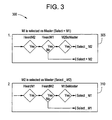
- FIG. 3 illustrates a state diagram 300 depicting selector state machine logic in accordance with example embodiments.
- the selector 150 is a piece of hardware that controls the power relay 160 that ultimately connects power converters for the controllers M1, M2 to the exciter field of the generator system.
- the selector 150 holds the controller M1, M2 state of the system 100 (i.e., controller M1 or controller M2 is the system 100 master).
- controller M1 is selected as master, but a transition to controller M2 as master occurs based on the controller M2 is heard by the selector 150 and either controller M1 is not heard for controller M2 requests to become master as described herein.
- controller M2 is selected as master, but a transition to controller M1 as master occurs based on the controller M1 is heard by the selector 150 and either controller M2 is not heard for controller M1 requests to become master as described herein.
- the system 100 chooses between the analog inputs 105, 106 data if there is a discrepancy.
- controllers M1, M2 There are various examples in which the choice of correctness when data differences between the peers.
- the following discussion describes several examples. For purposes of discussion, one controller can be referred to as “self”, and the other "peer”. It will be appreciated that there are several other example contemplated, and that the following examples are only illustrative and may be expanded to other signals.
- Example 1 For transformer (PT and CT) feedbacks, regardless of the value of the peer, a significant dc component is not a normal event and can constitute an instrumentation problem. On disagreement in magnitude and following a time delay: 1) Generator voltage magnitude, 2) Line/extra voltage magnitude, or 3) Generator current magnitude, a negative sequence component can be examined and a high value shall indicate a problem.
- Example 2 An estimate of regulator voltage (if a master) can be formed by the product of firing command and dc link voltage measurement. Regulator voltage minus the estimate forms an error signal conditional on cell gating active. On disagreement of regulator voltage by more than 10% nominal dc link: 1) If a master and a delay of 100ms and an error signal (>10%), or 2) If a backup and a delay of 200ms and an error signal from the master ( ⁇ 10%), then indicate a problem. For bridge malfunction (e.g., gating etc), if a master and an error signal (>10%) indicate a problem.
- each controller M1, M2 includes a processor, which can be part of an overall computer system.
- FIG. 4 illustrates an example embodiment of a system 400 that can be implemented with the controllers M1, M2.
- the methods described herein can be implemented in software (e.g., firmware), hardware, or a combination thereof.
- the methods described herein are implemented in software, as an executable program, and is executed by a special or general-purpose digital computer, such as a personal computer, workstation, minicomputer, or mainframe computer.
- the system 400 therefore includes general-purpose computer 401.
- the computer 401 includes a processor 405, memory 410 coupled to a memory controller 415, and one or more input and/or output (I/O) devices 440, 445 (or peripherals) that are communicatively coupled via a local input/output controller 435.
- the input/output controller 435 can be, but is not limited to, one or more buses or other wired or wireless connections, as is known in the art.
- the input/output controller 435 may have additional elements, which are omitted for simplicity, such as controllers, buffers (caches), drivers, repeaters, and receivers, to enable communications.
- the local interface may include address, control, and/or data connections to enable appropriate communications among the aforementioned components.
- the processor 405 is a hardware device for executing software, particularly that stored in memory 410.
- the processor 405 can be any custom made or commercially available processor, a central processing unit (CPU), an auxiliary processor among several processors associated with the computer 401, a semiconductor based microprocessor (in the form of a microchip or chip set), a macroprocessor, or generally any device for executing software instructions.
- the memory 410 can include any one or combination of volatile memory elements (e.g., random access memory (RAM, such as DRAM, SRAM, SDRAM, etc.)) and nonvolatile memory elements (e.g., ROM, erasable programmable read only memory (EPROM), electronically erasable programmable read only memory (EEPROM), programmable read only memory (PROM), tape, compact disc read only memory (CD-ROM), disk, diskette, cartridge, cassette or the like, etc.).
- RAM random access memory
- EPROM erasable programmable read only memory
- EEPROM electronically erasable programmable read only memory
- PROM programmable read only memory
- tape compact disc read only memory
- CD-ROM compact disc read only memory
- disk diskette
- cassette or the like etc.
- the memory 410 may incorporate electronic, magnetic, optical, and/or other types of storage media. Note that the memory 410 can have a distributed architecture, where various components are situated remote from one another, but can be accessed by the processor
- the software in memory 410 may include one or more separate programs, each of which comprises an ordered listing of executable instructions for implementing logical functions.
- the software in the memory 410 includes the dual controller generator regulating methods described herein in accordance with example embodiments and a suitable operating system (OS) 411.
- the OS 411 essentially controls the execution of other computer programs, such the dual controller generator regulating systems and methods as described herein, and provides scheduling, input-output control, file and data management, memory management, and communication control and related services.
- the dual controller generator regulating methods described herein may be in the form of a source program, executable program (object code), script, or any other entity comprising a set of instructions to be performed.
- a source program then the program needs to be translated via a compiler, assembler, interpreter, or the like, which may or may not be included within the memory 410, so as to operate properly in connection with the OS 411.
- the dual controller generator regulating methods can be written as an object oriented programming language, which has classes of data and methods, or a procedure programming language, which has routines, subroutines, and/or functions.
- a conventional keyboard 450 and mouse 455 can be coupled to the input/output controller 435.
- Other output devices such as the I/O devices 440, 445 may include input devices, for example but not limited to a printer, a scanner, microphone, and the like.
- the I/O devices 440, 445 may further include devices that communicate both inputs and outputs, for instance but not limited to, a network interface card (NIC) or modulator/demodulator (for accessing other files, devices, systems, or a network), a radio frequency (RF) or other transceiver, a telephonic interface, a bridge, a router, and the like.
- the system 400 can further include a display controller 425 coupled to a display 430.
- the system 400 can further include a network interface 460 for coupling to a network 465.
- the network 465 can be an IP-based network for communication between the computer 401 and any external server, client and the like via a broadband connection.
- the network 465 transmits and receives data between the computer 401 and external systems.
- network 465 can be a managed IP network administered by a service provider.
- the network 465 may be implemented in a wireless fashion, e.g., using wireless protocols and technologies, such as WiFi, WiMax, etc.
- the network 465 can also be a packet-switched network such as a local area network, wide area network, metropolitan area network, Internet network, or other similar type of network environment.
- the network 465 may be a fixed wireless network, a wireless local area network (LAN), a wireless wide area network (WAN) a personal area network (PAN), a virtual private network (VPN), intranet or other suitable network system and includes equipment for receiving and transmitting signals.
- LAN wireless local area network
- WAN wireless wide area network
- PAN personal area network
- VPN virtual private network
- the software in the memory 410 may further include a basic input output system (BIOS) (omitted for simplicity).
- BIOS is a set of essential software routines that initialize and test hardware at startup, start the OS 411, and support the transfer of data among the hardware devices.
- the BIOS is stored in ROM so that the BIOS can be executed when the computer 401 is activated.
- the processor 405 When the computer 401 is in operation, the processor 405 is configured to execute software stored within the memory 410, to communicate data to and from the memory 410, and to generally control operations of the computer 401 pursuant to the software.
- the dual controller generator regulating methods described herein and the OS 411, in whole or in part, but typically the latter, are read by the processor 405, perhaps buffered within the processor 405, and then executed.
- the methods can be stored on any computer readable medium, such as storage 420, for use by or in connection with any computer related system or method.
- aspects of the present invention may be embodied as a system, method or computer program product. Accordingly, aspects of the present invention may take the form of an entirely hardware embodiment, an entirely software embodiment (including firmware, resident software, micro-code, etc.) or an embodiment combining software and hardware aspects that may all generally be referred to herein as a "circuit,” “module” or “system.” Furthermore, aspects of the present invention may take the form of a computer program product embodied in one or more computer readable medium(s) having computer readable program code embodied thereon.
- the computer readable medium may be a computer readable signal medium or a computer readable storage medium.
- a computer readable storage medium may be, for example, but not limited to, an electronic, magnetic, optical, electromagnetic, infrared, or semiconductor system, apparatus, or device, or any suitable combination of the foregoing.
- a computer readable storage medium may be any tangible medium that can contain, or store a program for use by or in connection with an instruction execution system, apparatus, or device.
- a computer readable signal medium may include a propagated data signal with computer readable program code embodied therein, for example, in baseband or as part of a carrier wave. Such a propagated signal may take any of a variety of forms, including, but not limited to, electro-magnetic, optical, or any suitable combination thereof.
- a computer readable signal medium may be any computer readable medium that is not a computer readable storage medium and that can communicate, propagate, or transport a program for use by or in connection with an instruction execution system, apparatus, or device.
- Program code embodied on a computer readable medium may be transmitted using any appropriate medium, including but not limited to wireless, wireline, optical fiber cable, RF, etc., or any suitable combination of the foregoing.
- Computer program code for carrying out operations for aspects of the present invention may be written in any combination of one or more programming languages, including an object oriented programming language such as Java, Smalltalk, C++ or the like and conventional procedural programming languages, such as the "C" programming language or similar programming languages.
- the program code may execute entirely on the user's computer, partly on the user's computer, as a stand-alone software package, partly on the user's computer and partly on a remote computer or entirely on the remote computer or server.
- the remote computer may be connected to the user's computer through any type of network, including a local area network (LAN) or a wide area network (WAN), or the connection may be made to an external computer (for example, through the Internet using an Internet Service Provider).
- LAN local area network
- WAN wide area network
- Internet Service Provider for example, AT&T, MCI, Sprint, EarthLink, MSN, GTE, etc.
- These computer program instructions may also be stored in a computer readable medium that can direct a computer, other programmable data processing apparatus, or other devices to function in a particular manner, such that the instructions stored in the computer readable medium produce an article of manufacture including instructions which implement the function/act specified in the flowchart and/or block diagram block or blocks.
- the computer program instructions may also be loaded onto a computer, other programmable data processing apparatus, or other devices to cause a series of operational steps to be performed on the computer, other programmable apparatus or other devices to produce a computer implemented process such that the instructions which execute on the computer or other programmable apparatus provide processes for implementing the functions/acts specified in the flowchart and/or block diagram block or blocks.
- each block in the flowchart or block diagrams may represent a module, segment, or portion of code, which comprises one or more executable instructions for implementing the specified logical function(s).
- the functions noted in the block may occur out of the order noted in the figures. For example, two blocks shown in succession may, in fact, be executed substantially concurrently, or the blocks may sometimes be executed in the reverse order, depending upon the functionality involved.
- the dual controller generator regulating methods described herein can implemented with any or a combination of the following technologies, which are each well known in the art: a discrete logic circuit(s) having logic gates for implementing logic functions upon data signals, an application specific integrated circuit (ASIC) having appropriate combinational logic gates, a programmable gate array(s) (PGA), a field programmable gate array (FPGA), etc.
- ASIC application specific integrated circuit
- PGA programmable gate array
- FPGA field programmable gate array
Landscapes
- Engineering & Computer Science (AREA)
- Theoretical Computer Science (AREA)
- Physics & Mathematics (AREA)
- General Physics & Mathematics (AREA)
- Quality & Reliability (AREA)
- General Engineering & Computer Science (AREA)
- Automation & Control Theory (AREA)
- Safety Devices In Control Systems (AREA)
- Feedback Control In General (AREA)
Applications Claiming Priority (1)
| Application Number | Priority Date | Filing Date | Title |
|---|---|---|---|
| US13/204,325 US20130035772A1 (en) | 2011-08-05 | 2011-08-05 | Generator regulating system and method with dual controllers |
Publications (2)
| Publication Number | Publication Date |
|---|---|
| EP2555419A2 true EP2555419A2 (de) | 2013-02-06 |
| EP2555419A3 EP2555419A3 (de) | 2018-02-28 |
Family
ID=47172236
Family Applications (1)
| Application Number | Title | Priority Date | Filing Date |
|---|---|---|---|
| EP12179183.4A Withdrawn EP2555419A3 (de) | 2011-08-05 | 2012-08-03 | Generatorregelsystem und -verfahren mit zweifachen Reglern |
Country Status (3)
| Country | Link |
|---|---|
| US (1) | US20130035772A1 (de) |
| EP (1) | EP2555419A3 (de) |
| CN (1) | CN102969960A (de) |
Cited By (1)
| Publication number | Priority date | Publication date | Assignee | Title |
|---|---|---|---|---|
| CN109164787A (zh) * | 2018-08-31 | 2019-01-08 | 杭州和利时自动化有限公司 | 一种模拟量信号采集装置 |
Families Citing this family (9)
| Publication number | Priority date | Publication date | Assignee | Title |
|---|---|---|---|---|
| DE102008054589B3 (de) * | 2008-12-12 | 2010-08-19 | Thielert Aircraft Engines Gmbh | Motorsteuerungssystem für einen Flugdieselmotor |
| US9214797B2 (en) * | 2013-02-13 | 2015-12-15 | General Electric Company | Apparatus, systems, and methods for operation of a trip unit in a circuit protection device |
| CN104283485B (zh) * | 2013-07-09 | 2017-10-31 | 比亚迪股份有限公司 | 电动汽车及其电机控制系统和控制方法 |
| US9685819B2 (en) | 2014-04-25 | 2017-06-20 | Kohler, Co. | Redundant generator control |
| CN106452269A (zh) * | 2016-12-14 | 2017-02-22 | 合肥德仁智能科技有限公司 | 一种用于电动车辆的高可靠性交流电机控制装置 |
| US10620599B2 (en) * | 2018-01-04 | 2020-04-14 | General Electric Company | Distributed finite state machine configuration for controlling a physical asset |
| US11050651B2 (en) * | 2018-01-04 | 2021-06-29 | General Electric Company | Systems and methods for health monitoring and upgrade of a distributed controller |
| US11491930B2 (en) * | 2019-12-03 | 2022-11-08 | Woodward, Inc. | Systems and methods for commanded or uncommanded channel switchover in a multiple processor controller |
| CN111983997B (zh) * | 2020-08-31 | 2021-07-20 | 北京清大华亿科技有限公司 | 一种基于耦合性分析的控制回路性能监测方法及系统 |
Family Cites Families (11)
| Publication number | Priority date | Publication date | Assignee | Title |
|---|---|---|---|---|
| JPS5831602B2 (ja) * | 1976-02-04 | 1983-07-07 | 株式会社日立製作所 | 二重系制御装置 |
| DE19717686A1 (de) * | 1997-04-28 | 1998-10-29 | Itt Mfg Enterprises Inc | Schaltungsanordnung für ein Kraftfahrzeug-Regelungssystem |
| US6845467B1 (en) * | 2001-02-13 | 2005-01-18 | Cisco Systems Canada Co. | System and method of operation of dual redundant controllers |
| US7058170B2 (en) * | 2001-05-30 | 2006-06-06 | Siemens Communications, Inc. | Method for operating and apparatus for a back-plane supporting redundant circuit cards |
| WO2003032429A2 (en) * | 2001-10-12 | 2003-04-17 | Proton Energy Systems, Inc. | Method and system for bridging short duration power interruptions |
| DE102005005995A1 (de) * | 2004-02-23 | 2006-06-22 | Continental Teves Ag & Co. Ohg | Verfahren und Vorrichtung zum Überwachen von Signalverarbeitungseinheiten für Sensoren |
| US7290170B2 (en) * | 2004-04-07 | 2007-10-30 | International Business Machines Corporation | Arbitration method and system for redundant controllers, with output interlock and automatic switching capabilities |
| US7680034B2 (en) * | 2006-11-03 | 2010-03-16 | General Electric Company | Redundant control systems and methods |
| US7573145B2 (en) * | 2006-11-16 | 2009-08-11 | Cummins Power Generation Ip, Inc. | Electric power generation system controlled to reduce perception of operational changes |
| US8000859B2 (en) * | 2007-08-30 | 2011-08-16 | GM Global Technology Operations LLC | Duel control solenoid circuit |
| JP2011123545A (ja) * | 2009-12-08 | 2011-06-23 | Toshiba Corp | 比較冗長型情報処理装置 |
-
2011
- 2011-08-05 US US13/204,325 patent/US20130035772A1/en not_active Abandoned
-
2012
- 2012-08-03 EP EP12179183.4A patent/EP2555419A3/de not_active Withdrawn
- 2012-08-06 CN CN2012102766181A patent/CN102969960A/zh active Pending
Non-Patent Citations (1)
| Title |
|---|
| None |
Cited By (1)
| Publication number | Priority date | Publication date | Assignee | Title |
|---|---|---|---|---|
| CN109164787A (zh) * | 2018-08-31 | 2019-01-08 | 杭州和利时自动化有限公司 | 一种模拟量信号采集装置 |
Also Published As
| Publication number | Publication date |
|---|---|
| US20130035772A1 (en) | 2013-02-07 |
| CN102969960A (zh) | 2013-03-13 |
| EP2555419A3 (de) | 2018-02-28 |
Similar Documents
| Publication | Publication Date | Title |
|---|---|---|
| EP2555419A2 (de) | Generatorregelsystem und -verfahren mit zweifachen Reglern | |
| US20200124682A1 (en) | Systems and modules for testing uninterruptible power supply (ups) systems with multiple ups module | |
| US9122471B2 (en) | Identification of power source electrical connectivity | |
| CN102789529B (zh) | 故障预测方法、装置、系统和设备 | |
| JP2019505805A (ja) | 三相直列補償送電線における障害位置を判定するためのシステムおよび方法 | |
| WO2015130440A1 (en) | Topology determination using graph theory | |
| US9430007B2 (en) | Voltage regulator stress reducing system | |
| US20240200831A1 (en) | Method and apparatus for determining fault of heating apparatus, and electric water heater | |
| CN107924347B (zh) | 用于确定电气设备的平均故障时间的方法 | |
| JP2016063573A (ja) | 系統安定化システム | |
| US20130060397A1 (en) | Management of power distribution constraints | |
| CN104424603B (zh) | 用于处理配电网络中的用电量计量的方法和装置 | |
| US11462917B1 (en) | Methods, systems, and devices for maintenance and optimization of battery cabinets | |
| US10630084B2 (en) | Battery management system for extending service life of a battery | |
| US20250094273A1 (en) | Processor core fault handling method and apparatus, device, and storage medium | |
| US11474582B2 (en) | Automated validation of power topology via power state transitioning | |
| US20150331437A1 (en) | Systems and methods of monitoring bridging time | |
| JP6223832B2 (ja) | 系統安定化システム、保護継電装置、系統安定化方法及び系統安定化プログラム | |
| Ransom | Upgrading relay protection?—Be prepared | |
| WO2020206400A1 (en) | Microgrid control design system | |
| Cvijić et al. | Reliable adaptive optimization demonstration using big data | |
| JP7598951B2 (ja) | 診断装置、診断方法及びプログラム | |
| CN111146756B (zh) | 保护定值校核方法以及系统 | |
| JP7172186B2 (ja) | 空き容量算出装置、空き容量算出方法およびプログラム | |
| JP7467379B2 (ja) | 状態推定システム及び状態推定方法 |
Legal Events
| Date | Code | Title | Description |
|---|---|---|---|
| PUAI | Public reference made under article 153(3) epc to a published international application that has entered the european phase |
Free format text: ORIGINAL CODE: 0009012 |
|
| AK | Designated contracting states |
Kind code of ref document: A2 Designated state(s): AL AT BE BG CH CY CZ DE DK EE ES FI FR GB GR HR HU IE IS IT LI LT LU LV MC MK MT NL NO PL PT RO RS SE SI SK SM TR |
|
| AX | Request for extension of the european patent |
Extension state: BA ME |
|
| RIC1 | Information provided on ipc code assigned before grant |
Ipc: G05B 23/02 20060101ALI20170926BHEP Ipc: H02P 9/00 20060101AFI20170926BHEP Ipc: G06F 11/20 20060101ALI20170926BHEP Ipc: G05B 19/042 20060101ALI20170926BHEP Ipc: G06F 11/16 20060101ALI20170926BHEP Ipc: G06F 11/18 20060101ALI20170926BHEP |
|
| PUAL | Search report despatched |
Free format text: ORIGINAL CODE: 0009013 |
|
| AK | Designated contracting states |
Kind code of ref document: A3 Designated state(s): AL AT BE BG CH CY CZ DE DK EE ES FI FR GB GR HR HU IE IS IT LI LT LU LV MC MK MT NL NO PL PT RO RS SE SI SK SM TR |
|
| AX | Request for extension of the european patent |
Extension state: BA ME |
|
| RIC1 | Information provided on ipc code assigned before grant |
Ipc: G05B 23/02 20060101ALI20180125BHEP Ipc: G05B 19/042 20060101ALI20180125BHEP Ipc: G06F 11/18 20060101ALI20180125BHEP Ipc: G06F 11/16 20060101ALI20180125BHEP Ipc: G06F 11/20 20060101ALI20180125BHEP Ipc: H02P 9/00 20060101AFI20180125BHEP |
|
| STAA | Information on the status of an ep patent application or granted ep patent |
Free format text: STATUS: THE APPLICATION IS DEEMED TO BE WITHDRAWN |
|
| 18D | Application deemed to be withdrawn |
Effective date: 20180829 |