EP2555416A1 - Motor control device - Google Patents
Motor control device Download PDFInfo
- Publication number
- EP2555416A1 EP2555416A1 EP11762713A EP11762713A EP2555416A1 EP 2555416 A1 EP2555416 A1 EP 2555416A1 EP 11762713 A EP11762713 A EP 11762713A EP 11762713 A EP11762713 A EP 11762713A EP 2555416 A1 EP2555416 A1 EP 2555416A1
- Authority
- EP
- European Patent Office
- Prior art keywords
- region
- phase
- short
- circuit
- controllable
- Prior art date
- Legal status (The legal status is an assumption and is not a legal conclusion. Google has not performed a legal analysis and makes no representation as to the accuracy of the status listed.)
- Granted
Links
Images








Classifications
-
- B—PERFORMING OPERATIONS; TRANSPORTING
- B62—LAND VEHICLES FOR TRAVELLING OTHERWISE THAN ON RAILS
- B62D—MOTOR VEHICLES; TRAILERS
- B62D5/00—Power-assisted or power-driven steering
- B62D5/04—Power-assisted or power-driven steering electrical, e.g. using an electric servo-motor connected to, or forming part of, the steering gear
- B62D5/0457—Power-assisted or power-driven steering electrical, e.g. using an electric servo-motor connected to, or forming part of, the steering gear characterised by control features of the drive means as such
- B62D5/0481—Power-assisted or power-driven steering electrical, e.g. using an electric servo-motor connected to, or forming part of, the steering gear characterised by control features of the drive means as such monitoring the steering system, e.g. failures
- B62D5/0487—Power-assisted or power-driven steering electrical, e.g. using an electric servo-motor connected to, or forming part of, the steering gear characterised by control features of the drive means as such monitoring the steering system, e.g. failures detecting motor faults
-
- B—PERFORMING OPERATIONS; TRANSPORTING
- B62—LAND VEHICLES FOR TRAVELLING OTHERWISE THAN ON RAILS
- B62D—MOTOR VEHICLES; TRAILERS
- B62D5/00—Power-assisted or power-driven steering
- B62D5/04—Power-assisted or power-driven steering electrical, e.g. using an electric servo-motor connected to, or forming part of, the steering gear
- B62D5/0457—Power-assisted or power-driven steering electrical, e.g. using an electric servo-motor connected to, or forming part of, the steering gear characterised by control features of the drive means as such
- B62D5/0481—Power-assisted or power-driven steering electrical, e.g. using an electric servo-motor connected to, or forming part of, the steering gear characterised by control features of the drive means as such monitoring the steering system, e.g. failures
- B62D5/0484—Power-assisted or power-driven steering electrical, e.g. using an electric servo-motor connected to, or forming part of, the steering gear characterised by control features of the drive means as such monitoring the steering system, e.g. failures for reaction to failures, e.g. limp home
-
- H—ELECTRICITY
- H02—GENERATION; CONVERSION OR DISTRIBUTION OF ELECTRIC POWER
- H02P—CONTROL OR REGULATION OF ELECTRIC MOTORS, ELECTRIC GENERATORS OR DYNAMO-ELECTRIC CONVERTERS; CONTROLLING TRANSFORMERS, REACTORS OR CHOKE COILS
- H02P27/00—Arrangements or methods for the control of AC motors characterised by the kind of supply voltage
- H02P27/04—Arrangements or methods for the control of AC motors characterised by the kind of supply voltage using variable-frequency supply voltage, e.g. inverter or converter supply voltage
- H02P27/06—Arrangements or methods for the control of AC motors characterised by the kind of supply voltage using variable-frequency supply voltage, e.g. inverter or converter supply voltage using DC to AC converters or inverters
- H02P27/08—Arrangements or methods for the control of AC motors characterised by the kind of supply voltage using variable-frequency supply voltage, e.g. inverter or converter supply voltage using DC to AC converters or inverters with pulse width modulation
-
- H—ELECTRICITY
- H02—GENERATION; CONVERSION OR DISTRIBUTION OF ELECTRIC POWER
- H02P—CONTROL OR REGULATION OF ELECTRIC MOTORS, ELECTRIC GENERATORS OR DYNAMO-ELECTRIC CONVERTERS; CONTROLLING TRANSFORMERS, REACTORS OR CHOKE COILS
- H02P29/00—Arrangements for regulating or controlling electric motors, appropriate for both AC and DC motors
- H02P29/02—Providing protection against overload without automatic interruption of supply
- H02P29/032—Preventing damage to the motor, e.g. setting individual current limits for different drive conditions
Definitions
- the present invention relates to a motor control device for driving a three-phase brushless motor.
- the three-phasebrushlessmotorisusedas for example, ageneration source of a steering assist force in an electric power steering system.
- a driving circuit of a brushless motor used in an electric power steering system includes switching elements such as FETs (Field Effect Transistors) .
- FETs Field Effect Transistors
- the switching element fails, the brushless motor becomes a load when operating the steering wheel, and steering may become heavy.
- a relay is inserted in the connection between the brushless motor and the driving circuit.
- relays are inserted in motor connections of two phases, respectively, and when control is not performed and when the switching element fails, the relays are turned off.
- An object of the present invention is to provide a motor control device that enables driving of a three-phase brushless motor when one switching element in the driving circuit of the three-phase brushless motor has short-circuit faulted.
- a motor control device is for controlling a three-phase brushless motor (18) including a rotor and field coils, and includes a driving circuit (30) that includes three series circuits each formed by connecting two switching elements (31 UH and 31 UL ; 31 VH and 31 VL ; 31 WH and 31 WL ) in series corresponding to three phases, where the series circuits are connected in parallel between a power supply (33) and a ground (34), and regenerative diodes (32 UH and 32 UL ; 32 VH and 32 VL ; 32 WH and 32 WL ) are connected in parallel to the respective switching elements, and a controllable region identifying means (41) that identifies a rotor rotation angle region in which driving of the three-phase brushless motor is possible as a controllable region when one of the switching elements has short-circuit faulted.
- the alphanumeric characters in parentheses indicate corresponding components, etc., in preferred embodiments described later, and as a matter of course, the scope of the present invention
- a rotor rotation angle region in which driving of the three-phase brushless motor is possible is identified as a controllable region. Accordingly, even when one of the switching elements has short-circuit faulted, the three-phase brushless motor can be driven.
- the controllable region identification unit is arranged to identify a region consisting of the possible region and the indeterminate region or the possible region as the controllable region.
- one of the switching elements for example, a low-side switching element (31 VL ) of the V phase has short-circuit faulted.
- the V phase is a faulted phase
- other two phases that is, the U phase and the W phase are normal phases.
- a load current flows in a first closed circuit (61, refer to Fig.
- a load current flows in a second closed circuit (62, refer to Fig. 3 ) formed by the switching element (31 VL ) that has short-circuit faulted and the regenerative diode (32 WL ) connected in parallel to the low-side switching element (31 UL ) of the U phase that is one normal phase.
- a load current flows in a second closed circuit (62, refer to Fig. 3 ) formed by the switching element (31 VL ) that has short-circuit faulted and the regenerative diode (32 WL ) connected in parallel to the low-side switching element (31 WL ) of the W phase that is the other normal phase.
- the first rotation angle region and the second rotation angle region partially overlap, and in the overlapping region, a load current flows in both of the U phase and the W phase.
- a rotor rotation angle region in which a load current flows in both of the U phase and the W phase that are two normal phases is identified as an "impossible region”
- a rotor rotation angle region in which a load current flows in only the U phase that is one normal phase and a rotor rotation angle region in which a load current flows in only the W phase that is the other normal phase are identified as "indeterminate regions”
- a rotor rotation angle region in which a load current flows in neither of the normal phases is identified as a "possible region.”
- a region consisting of the "possible region” and the "indeterminate region” or the "possible region” is identified as a “controllable region.”
- controllable region identifying means is arranged to identify the controllable region based on phase voltages of the phases in the state where all switching elements other than a switching element that has short-circuit faulted are off.
- controllable region is identified based on phase voltages (induced voltages) of the phases in the state where all switching elements other than the switching element that has short-circuit faulted are off.
- a rotor rotation angle region in which phase voltages (V U and V W ) of both normal phases (U phase and W phase) become equal to or less than a phase voltage (V V ) of the short-circuit faulted phase (V phase in this example) (a region in which a load current flows in both first and second closed circuits (61 and 62)) is identified as an "impossible region.”
- a rotor rotation angle region in which phase voltages (V U and V W ) of both normal phases (U phase and V phase) become larger than the phase voltage (V V ) of the short-circuit faulted phase (V phase in this example) (a region in which a load current flows in neither of the first and second closed circuits (61 and 62)) is identified as a "possible region.”
- a rotor rotation region in which the phase voltages (V U and V W ) of both normal phases (U phase and W phase) become smaller than the phase voltage (V V ) of the short-circuit faulted phase (V phase in this example) (a region in which a load current flows in neither of the third and fourth closed circuits (63 and 64)) is identified as a "possible region.”
- a rotor rotation angle region in which the phase voltage of either one of the normal phases (U phase and W phase) becomes smaller than the phase voltage (V V ) of the short-circuit faulted phase (V phase in this example) and the phase voltage of the other normal phase becomes equal to or more than the phase voltage (V V ) of the short-circuit faulted phase (a region in which a load current flows in either one of the third and fourth closed circuits (63 and 64)) is defined as the "indeterminate region. " A region consisting of the "possible region” and the "indeterminate region”
- controllable region identifying means is arranged to identify the controllable region based on phase currents of the phases in a state where all switching elements other than the switching element that has short-circuit faulted are off. In this configuration, based on phase currents of the phases in the state where all switching elements other than the switching element that has short-circuit faulted are off, the controllable region is identified.
- a rotor rotation angle region in which phase currents (I U and I W ) of both U phase and W phase that are normal phases become larger than zero is identified as an "impossible region.”
- a rotor rotation angle region in which the phase currents (I U and I W ) of both U phase and W phase that are normal phases become zero or less is identified as a "possible region.”
- a rotor rotation angle region in which the polarity of the phase current of either one of the normal phases (U phase and W phase) becomes zero or less and the phase current of the other normal phase becomes larger than zero is identified as the
- a rotor rotation angle region in which phase currents (I U and I W ) of both U phase and W phase that are normal phases become smaller than zero (a region in which a load current flows in both of the third and fourth closed circuits (63 and 64)) is identified as an "impossible region.”
- a rotor rotation angle region in which the phase currents (I U and I W ) of both U phase and W phase that are normal phases become zero or more (a region in which a load current flows in neither of the third and fourth closed circuits (63 and 64)) is identified as a "possible region.”
- a rotor rotation angle region in which the polarity of the phase current of either one of the normal phases (U phase and W phase) becomes zero or more and the phase current of the other normal phase becomes smaller than zero (a region in which a load current flows in either one of the third and fourth closed circuits (63 and 64)) is identified as
- controllable region identifying means is arranged to identify a controllable region based on information showing the position of the switching element that has short-circuit faulted and information that is created in advance for identifying the controllable region from the position of the switching element that has short-circuit faulted.
- the controllable region is identified.
- a map in which, for each switching element, a "possible region,” an “indeterminate region,” and an “impossible region” corresponding to the case where the switching element has short-circuit faulted are stored is created in advance.
- a short-circuit fault occurs, based on information showing the position of the switching element that has short-circuit faulted and the map, a "possible region, " an "indeterminate region,” and an “impossible region” are identified.
- a region consisting of the "possible region” and the “indeterminate region” or the "possible region” is identified as a "controllable region.”
- controllable region identifying means is arranged to identify a controllable region based on information showing the position of the switching element that has short-circuit faulted, a direction of rotation of the three-phase brushless motor, and a map created in advance for identifying the controllable region from the position of the switching element that has short-circuit faulted and the direction of rotation of the three-phase brushless motor.
- the map may indicate, according to the directions of rotation of the three-phase brushless motor and the switching elements, controllable regions each corresponding to a case where each switching element has short-circuit faulted.
- the map may indicate a controllable region corresponding to a case where any one of the switching elements has short-circuit faulted, for example, when the three-phase brushless motor is rotated in either one direction of rotation of forward and reverse directions.
- controllable region identifying means may include a means that converts a controllable region indicated by the map into a controllable region corresponding to a position of the switching element that has short-circuit faulted and a direction of rotation of the three-phase brushless motor based on information showing the position of the switching element that has short-circuit faulted, the direction of rotation of the three-phase brushless motor, and the map.
- the motor control device further includes a fault position identifying means (41, S12) for identifying, when one of the switching elements has short-circuit faulted, the position of the switching element that has short-circuit faulted, and a motor control means (41, 43, S15) that drives the three-phase brushless motor by the normal phases when a rotor rotation angle is in the controllable region.
- a fault position identifying means 41, S12
- a motor control means 41, 43, S15
- the position of the switching element that has short-circuit faulted is identified. For example, based on the position of the switching element that has short-circuit faulted, a rotor rotation angle region in which driving of the three-phase brushless motor is possible is identified as a controllable region. Then, when the rotor rotation angle is in the controllable region, the three-phase brushless motor is driven. Accordingly, even when one of the switching elements has short-circuit faulted, the three-phase brushless motor can be driven.
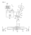
- Fig. 1 is a schematic view showing a general configuration of an electric power steering system to which a motor control device according to a preferred embodiment of the present invention is applied.
- the electric power steering system 1 includes a steering wheel 2 as a steering member, a turning mechanism 4 that turns steered wheels 3 in conjunction with rotation of the steering wheel 2, and a steering assist mechanism 5 for assisting driver' s steering.
- the steering wheel 2 and the turning mechanism 4 are mechanically joined via a steering shaft 6 and an intermediate shaft 7.
- the steering shaft 6 extends straight.
- the steering shaft 6 includes an input shaft 8 joined to the steering wheel 2 and an output shaft 9 joined to the intermediate shaft 7.
- the input shaft 8 and the output shaft 9 are joined rotatable relative to each other coaxially via a torsion bar 10. Specifically, when the steering wheel 2 is rotated, the input shaft 8 and the output shaft 9 rotate in the same direction while rotating relative to each other.
- a torque sensor 11 disposed around the steering shaft 6 detects a steering torque applied to the steering wheel 2 based on a relative rotational displacement of the input shaft 8 and the output shaft 9.
- the steering torque detected by the torque sensor 11 is input into an ECU (Electronic Control Unit) 12.
- ECU Electronic Control Unit
- a vehicle speed detected by a vehicle speed sensor 23 is input into the ECU 12.
- the turning mechanism 4 is a rack-and-pinion mechanism including a pinion shaft 13 and a rack shaft 14 as a turning shaft.
- a steered wheel 3 is joined via a tie rod 15 and a knuckle arm (not illustrated).
- the pinion shaft 13 is joined to the intermediate shaft 7.
- the pinion shaft 13 rotates in conjunction with steering of the steering wheel 2.
- the rack shaft 14 extends straight along the left-right direction (orthogonal to the straight direction) of the vehicle. At the intermediate portion in the axial direction of the rack shaft 14, a rack 17 that meshes with the pinion 16 is formed. By the pinion 16 and the rack 17, rotation of the pinion shaft 13 is converted into axial movement of the rack shaft 14. By moving the rack shaft 14 in the axial direction, the steered wheels 3 can be turned.
- the steering assist mechanism 5 includes a steering assisting electric motor 18 and a reduction gear mechanism 19 for transmitting an output torque of the electric motor 18 to the turning mechanism 4.
- the electric motor 3 is a three-phase brushless motor in the present preferred embodiment.
- the reduction gear mechanism 19 is a worm gear mechanism including a worm shaft 20 and a worm wheel 21 that meshes with the worm shaft 20.
- the reduction gear mechanism 19 is housed in a gear housing 22 as a transmission mechanism housing.
- the worm shaft 20 is driven to rotate by the electric motor 18.
- the worm wheel 21 is joined rotatably in the same direction as the direction of rotation of the steering shaft 6.
- the worm wheel 21 is driven to rotate by the worm shaft 20.
- the worm shaft 20 is driven to rotate by the electric motor 18, the worm wheel 21 is driven to rotate, and the steering shaft 6 rotates.
- the rotation of the steering shaft 6 is transmitted to the pinion shaft 13 via the intermediate shaft 7.
- the rotation of the pinion shaft 13 is converted into axial movement of the rack shaft 14. Accordingly, the steered wheels 3 are turned. Specifically, by rotationally driving the worm shaft 2 by the electric motor 18, the steered wheels 3 are turned.
- the electric motor 18 is controlled by an ECU 12 as a motor control device.
- the ECU 12 controls the electric motor 18 based on a steering torque detected by the torque sensor 11 and a vehicle speed detected by the vehicle speed sensor 23, etc.
- a target assist amount is determined by using a map in which the relationship between the steering torque and the target assist amount is stored for each vehicle speed, and control is performed to bring an assist force to be generated by the electric motor 18 close to the target assist amount.
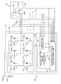
- Fig. 2 is a schematic view showing an electric configuration of the ECU 12 as a motor control device.
- the electric motor 18 includes a stator having a U-phase field coil 18U, a V-phase field coil 18V, and a W-phase field coil 18W, and a rotor to which permanent magnets to be subjected to repelling magnetic fields from the field coils 18U, 18V, and 18W are fixed.
- the ECU 12 includes a driving circuit 30 that generates driving power for the electric motor 18 and a control unit 40 for controlling the driving circuit 30.
- the control unit 40 consists of a microcomputer including a CPU and a memory (ROM, RAM, nonvolatile memory, etc.) storing operation programs, etc., for the CPU.
- the driving circuit 30 is a three-phase bridge inverter circuit.
- a series circuit of a pair of FETs (Field Effect Transistors) 31 UH and 31 UL corresponding to the U phase of the electric motor 18, a series circuit of a pair of FETs 31 VH and 31 VL corresponding to the V phase, and a series circuit of a pair of FETs 31 WH and 31 WL corresponding to the W phase are connected in parallel between a DC power supply 33 and a ground 34.
- regenerative diodes 32 UH to 32 WL are connected in parallel, respectively, in orientations that make a forward current flow from the ground 34 side to the DC power supply 33 side.
- the FET on the power supply side of the pair of FETs of each phase may be referred to as a "high-side FET” or “upper FET,” and the FET on the ground 34 side may be referred to as a “low-side FET” or “lower FET.”
- FETs 31 To collectively designate the six FETs 31 UH to 31 WL , they are referred to as “FETs 31.”
- regenerative diodes 32 UH to 32 WL they are referred to as "regenerative diodes 32.”
- the U-phase field coil 18U of the electric motor 18 is connected to a connection point between the pair of FETs 31 UH and 31 UL corresponding to the U phase.
- the V-phase field coil 18V of the electric motor 18 is connected to a connection point between the pair of FETs 31 VH and 31 VL corresponding to the V phase.
- the W-phase field coil 18W of the electric motor 18 is connected to the connection point between the pair of FETs 31 WH and 31 WL corresponding to the W phase.
- current sensors 51 U , 51 V , and 51 W for detecting phase currents I U , I V , and I W of the phases are provided on the electric motor 18 side.
- a rotation angle sensor 52 such as a resolver for detecting a rotation angle (electric angle) of the rotor is provided.
- the control unit 40 functions as a plurality of functional processing units by executing predetermined operation programs stored in the memory.
- the plurality of functional processing units include a controllable region identification unit 41, a sine wave driving unit 42, and a driving unit 43 for time of short-circuit fault.
- the sine wave driving unit 42 drives the electric motor 18 by 180-degree energization sine wave driving by controlling the FETs 31 in a normal state where no fault occurs.
- a rotor rotation angle (electric angle) detected by the rotation angle sensor 52 a steering torque detected by the torque sensor 11, a vehicle speed detected by the vehicle speed sensor 23, and phase currents I U , I V , and I W detected by the current sensors 51 U , 51 V , and 51 W , are input.
- the sine wave driving unit 42 determines a target assist amount based on, for example, the map in which the relationship between the steering torque and the target assist amount (current target value) is stored for each vehicle speed, the steering torque detected by the torque sensor 11, and the vehicle speed detected by the vehicle speed sensor 23. Then, the sine wave driving unit 42 PWM (Pulse Width Modulation)-controls the FETs 31 so that the assist force (torque) to be generated by the electric motor 18 becomes close to the target assist amount based on the target assist amount, the phase currents I U , I V , and I W of the phases detected by the current sensors 51 U , 51 V , and 51 W , and the rotor rotation angle (electric angle) detected by the rotation angle sensor 52.
- PWM Pulse Width Modulation
- the controllable region identification unit 41 performs control for stopping driving of the electric motor 18 when an abnormality of the electric motor 18 is detected, determination as to whether a short-circuit fault has occurred in the FETs 31, identification of the position of an FET that has short-circuit faulted when a short-circuit fault has occurred in the FET 31, and identification of a controllable region.
- the controllable region is a rotor rotation angle region (electric angle region) in which the electric motor 18 can be driven when one of the six FETs 31 UH to 31 WL has short-circuit faulted.
- controllable region identification unit 41 identifies an electric angle region in which a load current flows in neither of the two normal phases is identified as a "possible region,” an electric angle region in which a load current flows in either one of the two normal phases is identified as an “indeterminate region,” and an electric angle region in which a load current flows in both of the two normal phases is identified as an "impossible region.”
- a region of the combination of the "possible region” and “indeterminate region” is identified as a controllable region in which the electric motor 18 can be driven, and the "impossible region” is identified as an uncontrollable region in which the electric motor 18 cannot be driven. It is also possible that only the “possible region” is identified as a controllable region in which the electric motor 18 can be driven, and a region of the combination of the "indeterminate region” and "impossible region” is identified as an uncontrollable region in which the electric motor 18 cannot be driven.
- the first closed circuit 61 includes the low-side FET 31 VL of the V phase that has short-circuit faulted, the regenerative diode 32 UL connected in parallel to the low-side FET 31 UL of the U phase that is a normal phase, the U-phase field coil 18U, and the V-phase field coil 18V.
- the second closed circuit 62 includes the low-side FET 31 VL of the V phase that has short-circuit faulted, the regenerative diode 32 WL connected in parallel to the low-side FET 31 WL of the W phase that is a normal phase, the W-phase field coil 18W, and the V-phase field coil 18V.
- the "impossible region,” the "possible region,” and the “indeterminate region” are as follows. That is, an electric angle region in which a load current flows in both of the first closed circuit 61 and the second closed circuit 62 is the “impossible region.” On the other hand, an electric angle region in which a load current flows in neither of the first closed circuit 61 and the second closed circuit 62 is the “possible region.” An electric angle region in which a load current flows in either one of the first closed circuit 61 and the second closed circuit 62 is the "indeterminate region.”
- the third closed circuit 63 includes the high-side FET 31 VH of the V phase that has short-circuit faulted, the V-phase field coil 18V, the U-phase field coil 18U, and the regenerative diode 32 UH connected in parallel to the high-side FET 31 UH of the U phase that is a normal phase.
- the fourth closed circuit 64 includes the high-side FET 31 VH of the V phase that has short-circuit faulted, the V-phase field coil 18V, the W-phase field coil 18W, and the regenerative diode 32 WH connected in parallel to the high-side FET 31 WH of the W phase that is a normal phase.
- the "impossible region,” the "possible region,” and the “indeterminate region” are as follows. That is, an electric angle region in which a load current flows in both of the third closed circuit 63 and the fourth closed circuit 64 is the “impossible region.” On the other hand, an electric angle region in which a load current flows in neither of the third closed circuit 63 and the fourth closed circuit 64 is the “possible region.” An electric angle region in which a load current flows in either one of the third closed circuit 63 and the fourth closed circuit 64 is the "indeterminate region.”
- the phase voltage V V of the V phase that is a short-circuit faulted phase must be higher (larger) than the phase voltage V U of the U phase that is a normal phase.
- the polarity of a current flowing from the driving circuit 30 toward the electric motor 18 is positive, the polarity of the phase current I U of the U phase that is a normal phase is positive.
- the phase voltage V V of the V phase that is a short-circuit faulted phase must be higher than the phase voltage V W of the W phase that is a normal phase.
- the polarity of the phase current I W of the W phase that is a normal phase is positive.
- the phase voltage V V of the V phase that is a short-circuit faulted phase must be lower (smaller) than the phase voltage V U of the U phase that is a normal phase.
- the polarity of the phase current I U of the U phase that is a normal phase becomes negative.
- the phase voltage V V of the V phase that is a short-circuit faulted phase must be lower than the phase voltage V W of the W phase that is a normal phase.
- the polarity of the phase current I W of the W phase that is a normal phase becomes negative.
- the driving unit 43 for time of short-circuit fault performs a process for driving the electric motor 18 in the "possible region” and "indeterminate region” identified by the controllable region identification unit 41.
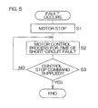
- Fig. 5 is a flowchart showing operations of the control unit 40 when a fault occurs.
- the controllable region identification unit 41 detects occurrence of an operation failure (fault) in the electric motor 18 during 180-degree energization sine wave driving of the electric motor 18 by the sine wave driving unit 42
- the controllable region identification unit 41 supplies a motor stop command to the sine wave driving unit 42 (Step S1).
- the sine wave driving unit 42 receives the motor stop command from the fault determination unit 41, the sine wave driving unit 42 interrupts 180-degree energization sine wave driving and turns all FETs 31 off. Accordingly, the electric motor 18 is stopped.
- Step S2 the controllable region identification unit 41 and the driving unit 43 for time of short-circuit fault perform a motor control process for the time of a short-circuit fault.
- the motor control process for the time of a short-circuit fault is continuously performed until a control stop command such as a power supply turning-off command is supplied (Step S3: YES).
- Fig. 6 is a flowchart showing procedures of a motor control process for the time of a short-circuit fault.
- the controllable region identification unit 41 determines whether the FET that has short-circuit faulted (the position of the FET that has short-circuit faulted) has already been identified (Step S11). Specifically, it is determined whether it has already been identified of which phase among the three phases the FET that has short-circuit faulted is, and whether the FET that has short-circuit faulted is the high-side or low-side FET.
- the controllable region identification unit 41 performs processes for determining whether a short-circuit fault has occurred and for identifying an FET that has short-circuit faulted when a short-circuit fault has occurred based on phase voltages (induced voltages) V U , V V , and V W of the phases (Step S12).
- the controllable region identification unit 41 performs a primary determination process. In the primary determination process, the controllable region identification unit 41 acquires phase voltages V U , V V , and V W of the phases.
- the controllable region identification unit 41 investigates whether a first condition that any of the phase voltages is equal to or less than a predetermined ground level VG (for example, 0.5 [V]) is satisfied and whether a second condition that any of the phase voltages is equal to or more than a predetermined power supply level VB (for example, 5.0 [V]).
- a predetermined ground level VG for example, 0.5 [V]
- VB for example, 5.0 [V]
- the controllable region identification unit 41 When it could be identified whether the FET that has short-circuit faulted is the high-side FET or the low-side FET through the primary determination process, the controllable region identification unit 41 performs a secondary determination process. In the secondary determination process, the controllable region identification unit 41 applies a current to the electric motor 18 by controlling the FETs 31 according to an electric angle (forced commutation control). Then, the controllable region identification unit 41 monitors the phase voltages V U , V V , and V W of the phases, and based on waveforms of these voltages, identifies a phase (short-circuit faulted phase) of the FET that has short-circuit faulted. Accordingly, an FET that has short-circuit faulted can be identified.
- Step S13 In a case where an FET that has short-circuit faulted cannot be identified by the process of Step S12 (including the case where a short-circuit fault has not occurred) (Step S13: NO), the process shifts to Step S3 in Fig. 5 . In Step S3, when a control end command is not supplied, the process returns to Step S11. When it has already been identified whether the FET that has short-circuit faulted is the high-side FET or the low-side FET at the time of start of the process of Step S12, the controllable region identification unit 41 starts the secondary determination process without performing the first determination process.
- Step S14 the controllable region identification unit 41 performs a controllable region identification process.
- the controllable region identification unit 41 identifies a "possible region,” an "indeterminate region,” and an "impossible region” corresponding to the FET that has short-circuit faulted and the direction in which the electric motor 18 should be rotated.
- the direction of rotation in which the electric motor 18 should be rotated is determined based on, for example, an output signal of the torque sensor 11 as described later. Details of the controllable region identification process are described later.
- Step S15 When the regions ("possible region,” “indeterminate region,” and “impossible region) corresponding to the FET that has short-circuit faulted and the direction in which the electric motor 18 should be rotated are identified by the controllable region identification process, the controllable region identification unit 41 and the driving unit 43 for time of short-circuit fault perform motor control corresponding to a region to which the current electric angle belongs among the identified "possible region, "indeterminate region,” and “impossible region” (Step S15).
- the driving unit 43 for time of short-circuit fault drives the electric motor 18.
- the driving unit 43 for time of short-circuit fault does not drive the electric motor 18. Details of the process of Step S15 are described later.
- Step S11 when it is determined that the FET that has short-circuit faulted has already been identified (Step S11: YES), based on the direction in which the electric motor 18 should be rotated and predetermined information that has already been identified, the controllable region identification unit 41 identifies the regions ("possible region,” “indeterminate region,” and “impossible region”) corresponding to the FET that has short-circuit faulted and the direction in which the electric motor 18 should be rotated, and then the process shifts to Step S15.
- the predetermined information is information showing the regions ("possible regions,” “indeterminate regions,” and “impossible regions") by direction of rotation corresponding to the short-circuit faulted FET that has already been identified in Step S14.
- the predetermined information is the short-circuit faulted FET that has already been identified and map data (map data shown in Fig. 9 ) to be adopted in the third method.
- the predetermined information is the short-circuit faulted FET that has already been identified and map data to be adopted in the fourth method (map data showing the "possible region,” “indeterminate region,” and “impossible region” corresponding to a case where any one of the FETs 31 has short-circuit faulted while the electric motor 18 is rotated in either one of direction of rotation).
- controllable region identification process in Step S14 is described.
- a method for identifying the controllable region the following three methods are available.
- a controllable region is identified in a state where induced voltages are generated. Accordingly, the rotor must be rotated. Therefore, when the electric motor 18 is rotated by driver's steering operation, a controllable region can be identified in this state, however, when the electric motor 18 is not rotated by a steering operation, the controllable region identification unit 41 must forcibly rotationally drive the electric motor 18 by controlling the FETs 31 according to an electric angle.
- a controllable region is identified based on a map created in advance, so that the rotor does not need to be rotated.
- the direction of rotation of the electric motor 18 includes a forward (CW: clockwise) direction and a reverse (CCW: counterclockwise) direction. Between the forward direction and the reverse direction, the induced voltage waveforms of the phases differ even when the FET that has short-circuit faulted is the same, so that the controllable region differs between the directions, however, the concept of the method for identifying a controllable region is the same.
- the direction of rotation of the rotor is the forward direction.
- the direction of rotation of the electric motor 18 can be identified based on a change in electric angle detected by the rotation angle sensor 52. For example, when the electric angle changes to increase, the direction of rotation of the electric motor 18 is identified as the forward direction, and when the electric angle changes to decrease, the direction of rotation of the electric motor 18 is identified as the reverse direction.
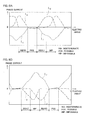
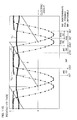
- Fig. 3 shows phase voltages (induced voltages) V U , V V , and V W of the phases when the rotor of the electric motor 18 is rotated in the forward direction by a steering operation in the case where the low-side FET 31 VL of the V phase has short-circuit faulted.
- the controllable region identification unit 41 identifies an electric angle region in which the phase voltages V U and V W of both normal phases (U phase and the W phase) become equal to or less than the phase voltage V V of the short-circuit faulted phase (V phase in this example) (an electric angle region in which a load current flows in both of the first and second closed circuits 61 and 62) as an "impossible region.”
- the electric angle is obtained from the rotation angle sensor 52.
- the controllable region identification unit 41 identifies an electric angle region in which the phase voltages V U and V W of both normal phases (U phase and W phase) become larger than the phase voltage V V of the short-circuit faulted phase (V phase in this example) (an electric angle region in which a load current flows in neither of the first and second closed circuits 61 and 62) as a "possible region.”
- the controllable region identification unit 41 may identify an electric angle region in which the phase voltage of one normal phase A becomes equal to or more than the phase voltage of the other normal phase B as a "possible region (A)", and identify an electric angle region in which the phase voltage of the other normal phase B becomes larger than the phase voltage of the one normal phase A as a "possible region (B).”
- the controllable region identification unit 41 may identify an electric angle region in which the phase voltage of one normal phase A becomes equal to or more than the phase voltage of the other normal phase B as a "possible region (A)", and identify an electric angle region in which
- the controllable region identification unit 41 identifies an electric angle region in which the phase voltage of either one of the normal phases (U phase and W phase) becomes larger than the phase voltage V V of the short-circuit faulted phase (V phase in this example) and the phase voltage of the other normal phase becomes equal to or less than the phase voltage V V of the short-circuit faulted phase (an electric angle region in which a load current flows in either one of the first and second closed circuits 61 and 62) as an "indeterminate region.”
- the FET that has short-circuit faulted is a low-side FET
- the controllable region identification unit 41 may identify an electric angle region in which the phase voltage of one normal phase A becomes larger than the phase voltage of the faulted phase C as an "indeterminate region (A),” and identify an electric angle region in which the phase voltage of the other normal phase B becomes larger than the phase voltage of the
- controllable region identification unit 41 may identify an electric angle region in which the phase voltage V U of the U phase that is a normal phase becomes larger than the phase voltage V V of the V phase and the phase voltage V W of the W phase that is a normal phase becomes equal to or less than the phase voltage V V of the V phase (an electric angle region in which a load current flows in only the second closed circuit 62 including the W-phase field coil 18W of the first and second closed circuits 61 and 62) as an "indeterminate region (U)."
- the controllable region identification unit 41 may identify an electric angle region in which the phase voltage V W of the W phase that is a normal phase becomes larger than the phase voltage V V of the V phase and the phase voltage V U of the U phase that is a normal phase becomes equal to or less than the phase voltage V V of the V phase (an electric angle region in which a load current flows in only the first closed circuit 61 including the U-phase field coil 18U of the first and second closed circuits 61 and 62
- a high-side FET has short-circuit faulted.
- Fig. 4 the case where the high-side FET 31 VH of the V phase has short-circuit faulted is described by way of example.
- Fig. 7B shows phase voltages (induced voltages) V U , V V , and V W of the phases when the rotor of the electric motor 18 is rotated in the forward direction by a steering operation in the case where the high-side FET 31 VH of the V phase has short-circuit faulted.
- the controllable region identification unit 41 identifies an electric angle region in which the phase voltages V U and V W of both normal phases (U phase and W phase) become equal to or more than the phase voltage V V of the short-circuit faulted phase (V phase in this example) (an electric angle region in which a load current flows in both of the third and fourth closed circuits 63 and 64) as an "impossible region.”
- the controllable region identification unit 41 identifies an electric angle region in which the phase voltages V U and V W of both normal phases (U phase and W phase) become smaller than the phase voltage V V of the short-circuit faulted phase (V phase in this example) (an electric angle region in which a load current flows in neither of the third and fourth closed circuits 63 and 64) as a "possible region.”
- the controllable region identification unit 41 may identify an electric angle region in which the phase voltages V U and V W of both normal phases (U phase and W phase) become equal to or more than the phase voltage V V of the short-
- the controllable region identification unit 41 identifies an electric angle region in which the phase voltage of either one of the normal phases (U phase and W phase) becomes smaller than the phase voltage V V of the short-circuit faulted phase (V phase in this example) and the phase voltage of the other normal phase becomes equal to or more than the phase voltage V V of the short-circuit faulted phase (an electric angle region in which a load current flows in either one of the third and fourth closed circuits 63 and 64) as an "indeterminate region.”
- the controllable region identification unit 41 may identify an electric angle region in which the phase voltage of one normal phase A becomes smaller than the phase voltage of the faulted phase C as an "indeterminate region (A) " and identify an electric angle region in which the phase voltage of the other normal phase B becomes smaller than the phase voltage of the faulte
- controllable region identification unit 41 may identify an electric angle region in which the phase voltage V U of the U phase that is a normal phase becomes smaller than the phase voltage V V of the V phase and the phase voltage V W of the W phase that is a normal phase becomes equal to or more than the phase voltage V V of the V phase (an electric angle region in which a load current flows in only the fourth closed circuit 64 including the W-phase field coil 18W of the third and fourth closed circuits 63 and 64) as an "indeterminate region (U) .”
- the controllable region identification unit 41 may identify an electric angle region in which the phase voltage V W of the W phase that is a normal phase becomes smaller than the phase voltage V V of the V phase and the phase voltage V U of the U phase that is a normal phase becomes equal to or more than the phase voltage V V of the V phase (an electric angle region in which a load current flows in only the third closed circuit 63 including the U-phase field coil 18U of the third and fourth closed circuits 63 and 64) as
- the controllable region identification unit 41 identifies the "possible region,” “indeterminate region,” and “impossible region” when the electric motor 18 is rotated in the other direction of rotation.
- the "possible region,” “indeterminate region,” and “impossible region” when the electric motor 18 is rotated in the forward direction and the possible region, “ “indeterminate region,” and “impossible region” when the electric motor 18 is rotated in the reverse direction are different from each other by 180 degrees in terms of electric angle. Therefore, in a case where the "possible region,” “indeterminate region,” and “impossible region” when the electric motor 18 is rotated in one direction of rotation have been identified, the “possible region,” “indeterminate region,” and “impossible region” when the electric motor 18 is rotated in the other direction of rotation can be identified based on the identified “possible region,” “indeterminate region,” and “impossible region.”
- region regulating electric angles ⁇ electric angles that regulate these regions
- the controllable region identification unit 41 identifies the "possible region,” “indeterminate region,” and “impossible region” corresponding to the FET that has short-circuit faulted and the direction of rotation in which the electric motor 18 should be rotated based on the direction of rotation in which the electric motor 18 should be rotated and the regions ("possible region,” “indeterminate region,” and “impossible region”) corresponding to the forward direction and the regions ("possible region,” “indeterminate region,” and “impossible region”) corresponding to the reverse direction identified by the first method.
- the direction of rotation in which the electric motor 18 should be rotated is determined based on, for example, an output signal of the torque sensor 11. In detail, based on whether the output signal of the torque sensor 11 indicates a clockwise steering torque or a counterclockwise steering torque, the direction in which the electric motor 18 should be rotated is determined. Specifically, when the output signal of the torque sensor 11 indicates a clockwise steering torque, a direction of rotation for generating a torque that assists clockwise steering is determined as the direction of rotation in which the electric motor 18 should be rotated. On the other hand, when the output signal of the torque sensor 11 indicates a counterclockwise steering torque, a direction of rotation for generating a torque that assists counterclockwise steering is determined as the direction of rotation in which the electric motor 18 should be rotated.
- phase currents detected by the current sensors 51 U , 51 V , and 51 W are input into the controllable region identification unit 41.
- the induced voltage waveforms of the phases differ even when the FET that has short-circuit faulted is the same, so that the controllable region differs between the directions, however, the concept of the method for identifying a controllable region is the same.
- the direction of rotation of the rotor is the forward direction.
- Fig. 3 a case where the low-side FET 31 VL of the V phase has short-circuit faulted is described by way of example.
- Fig. 8A shows phase currents I U , I V , and I W of the phases when the rotor of the electric motor 18 is rotated in the forward direction by a steering operation in the case where the low-side FET 31 VL of the V phase has short-circuit faulted.
- the controllable region identification unit 41 identifies an electric angle region in which the phase currents I U and I W of both U phase and W phase that are normal phases become larger than zero (an electric angle region in which a load current flows in both of the first and second closed circuits 61 and 62) as an "impossible region.”
- the controllable region identification unit 41 identifies an electric angle region in which the phase currents I U and I W of both U phase and W phase that are normal phases become zero or less (an electric angle region in which a load current flows in neither of the first and second closed circuits 61 and 62) as a "possible region.”
- the controllable region identification unit 41 identifies an electric angle region in which the phase current of either one of the normal phases (U phase and W phase) becomes zero or less and the phase current of the other normal phase becomes larger than zero as an "indeterminate region.”
- the controllable region identification unit 41 may identify an electric angle region in which the phase current of one normal phase A becomes zero or less as an "indeterminate region (A),” and identify an electric angle region in which the phase current of the other normal phase B becomes zero or less as an "indeterminate region (B).
- controllable region identification unit 41 may identify an electric angle region in which the phase current I U of the U phase that is a normal phase becomes zero or less and the phase current I W of the W phase that is a normal phase becomes larger than zero (an electric angle region in which a load current flows in only the second closed circuit 62 including the W-phase field coil 18W of the first and second closed circuits 61 and 62) as an "indeterminate region (U)."
- the controllable region identification unit 41 may identify an electric angle region in which the phase current I W of the W phase that is a normal phase becomes zero or less and the phase current I U of the U phase that is a normal phase becomes larger than zero (an electric angle region in which a load current flows in only the first closed circuit 61 including the U-phase field coil 18U of the first and second closed circuits 61 and 62) as an "indeterminate region (W)."
- a high-side FET has short-circuit faulted.
- Fig. 4 the case where the high-side FET 31 VH of the V phase has short-circuit faulted is described by way of example.
- Fig. 8B shows phase currents I U , I V , and I W when the rotor of the electric motor 18 is rotated in the forward direction by a steering operation in the case where the high-side FET 31 VH of the V phase has short-circuit faulted.
- the controllable region identification unit 41 identifies an electric angle region in which the phase currents I U and I W of both U phase and W phase that are normal phases become smaller than zero (an electric angle region in which a load current flows in both of the third and fourth closed circuits 63 and 64) as an "impossible region.”
- the controllable region identification unit 41 identifies an electric angle region in which the phase currents I U and I W of both U phase and W phase that are normal phases become zero or more (an electric angle region in which a load current flows in neither of the third and fourth closed circuits 63 and 64) as a "possible region.”
- the controllable region identification unit 41 identifies an electric angle region in which the polarity of the phase current of either one of the normal phases (U phase and W phase) becomes zero or more and the phase current of the other normal phase becomes smaller than zero as an "indeterminate region. "
- the controllable region identification unit 41 may identify an electric angle region in which the phase current of one normal phase A becomes zero or more as an "indeterminate region (A),” and identify an electric angle region in which the phase current of the other normal phase B becomes zero or more as an "indeterminate region (B).
- controllable region identification unit 41 may identify an electric angle region in which the phase current I U of the U phase that is a normal phase becomes zero or more and the phase current I W of the W phase that is a normal phase becomes smaller than zero (an electric angle region in which a load current flows in only the fourth closed circuit 64 including the W-phase field coil 18W of the third and fourth closed circuits 63 and 64) as an "indeterminate region (U)."
- the controllable region identification unit 41 may identify an electric angle region in which the phase current I W of the W phase that is a normal phase becomes zero or more and the phase current I U of the U phase that is a normal phase becomes smaller than zero (an electric angle region in which a load current flows in only the third closed circuit 63 including the U-phase field coil 18U of the third and fourth closed circuits 63 and 64) as an "indeterminate region (W)."
- the controllable region identification unit 41 identifies the "possible region,” “indeterminate region,” and “impossible region” when the electric motor 18 is rotated in the other direction of rotation by the same manner as in the first method.
- the controllable region identification unit 41 identifies the "possible region,” “indeterminate region,” and “impossible region” corresponding to the FET that has short-circuit faulted and the direction of rotation in which the electric motor 18 should be rotated based on the direction of rotation in which the electric motor 18 should be rotated and the regions ("possible region,” “indeterminate region,” and “impossible region”) corresponding to the forward direction and the regions ("possible region,” “indeterminate region,” and “impossible region”) corresponding to the reverse direction identified by the second method.
- the direction of rotation in which the electric motor 18 should be rotated is determined based on, for example, an output signal of the torque sensor 11.
- a map showing the "possible region,” “indeterminate region,” and “impossible region” corresponding to each case where each FET has short-circuit faulted according to the direction of rotation (CW, CCW) of the electric motor 18 and the FET is created in advance and stored in a nonvolatile memory.
- Fig. 9 shows an example of contents in such a map.
- CW and CCW denote the directions of rotation of the electric motor 18 when the electric motor 18 is driven in Step S15 in Fig. 6
- CW indicates the forward direction
- CCW indicates the reverse direction.
- U, V, W, upper and lower denote the position of the FET that has short-circuit faulted.
- each of U, V, and W denotes a phase corresponding to the FET that has short-circuit faulted.
- “Upper” indicates that the FET that has short-circuit faulted is an upper FET (high-side FET), and “lower” indicates that the FET that short-circuit faulted is a lower FET (low-side FET).
- This map is created based on theoretical values or measured data.
- the controllable region identification unit 41 identifies the "possible region,” “indeterminate region,” and “impossible region” corresponding to the FET that has short-circuit faulted and the direction in which the electric motor 18 should be rotated based on the direction of rotation in which the electric motor 18 should be rotated, the position of the FET 31 that has short-circuit faulted, and the map.
- the direction of rotation in which the electric motor 18 should be rotated is determined based on, for example, an output signal of the torque sensor 11.
- Fig. 10 shows theoretical values (simulation values) of induced voltage waveforms V U , V V , and V W of the phases and the electric angle ⁇ in normal driving.
- the direction of rotation is the forward (CW) direction.
- a point at which the induced voltage waveform of the U phase changes from positive to negative in normal driving is set as an electric angle ⁇ of 0°.
- V U , V V , V W of induced voltages of the phases in normal driving are expressed by the following equations (3) provided that E is an amplitude.
- V W E ⁇ sin ⁇ - ⁇ + 2 / 3 ⁇
- Fig. 11A shows theoretical values (simulation values) of induced voltage waveforms V U ', V V ', and V W ' of the phases with respect to the electric angle ⁇ when it is assumed that the low-side FET 31 VL of the V phase has short-circuit faulted.
- an electric angle region in which the induced voltages V U ' and V W ' of both normal phases (U phase and V phase) become larger than the induced voltage V V ' of the short-circuit faulted phase (V phase) is obtained as a "possible region.
- a region (in this example, 210° to 270°) in which the induced voltage V U ' of the U phase becomes equal to or more than the induced voltage V W ' of the W phase is obtained as a "possible region (U)," and a region (in this example, 150° to 210°) in which the induced voltage V W ' of the W phase becomes equal to or more than the induced voltage V U ' of the U phase is obtained as a "possible region (W) .”
- An electric angle region (330° to 90° in this example) in which the induced voltages V U ' and V W ' of both normal phases (U phase and V phase) become equal to or less than the induced voltage V V ' of the short-circuit faulted phase (V phase) is obtained as an "impossible region.”
- electric angle regions (90° to 150° and 270° to 330°) between the "possible region” and the “impossible region” are obtained as “indeterminate regions.
- the electric angle region (270° to 330°) in which the induced voltage V U ' of the U phase becomes larger than the induced voltage V V ' of the short-circuit faulted phase (V phase) is obtained as an "indeterminate region (U)
- the electric angle region (90° to 150°) in which the induced voltage V W ' of the W phase becomes larger than the induced voltage V V ' of the short-circuit faulted phase (V phase) is obtained as an "indeterminate region (W).”
- Fig. 11B shows theoretical values (simulation values) of the induced voltage waveforms V U ', V V ', and V W ' of the phases with respect to the electric angle ⁇ when it is assumed that the high-side FET 31 VH of the V phase has short-circuit faulted.
- the direction of rotation of the electric motor 18 is the forward (CW) direction.
- an electric angle region (330° to 90° in this example) in which the induced voltages V U ' and V W ' of both normal phases (U phase and V phase) become smaller than the induced voltage V V ' of the short-circuit faulted phase (V phase) is obtained as a "possible region.”
- a region (30° to 90° in this example) in which the induced voltage V U ' of the U phase becomes equal to or less than the induced voltage V W ' of the W phase is obtained as a "possible region (U),” and a region (330° to 30° in this example) in which the induced voltage V W ' of the W phase becomes smaller than the induced voltage V U ' of the U phase is obtained as a "possible region (W).”
- an electric angle region (150° to 270° in this example) in which the induced voltages V U ' and V W ' of both normal phases (U phase and V phase) become equal to or more
- Electric angle regions (90° to 150° and 270° to 330°) between the "possible region” and the “impossible region” are obtained as “indeterminate regions.”
- the electric angle region (90° to 150°) in which the induced voltage V U ' of the U phase becomes smaller than the induced voltage V V ' of the short-circuit faulted phase (V phase) is obtained as an "indeterminate region (U)
- the electric angle region (270° to 330°) in which the induced voltage V W ' of the W phase becomes smaller than the induced voltage V V ' of the short-circuit faulted phase (V phase) is obtained as an "indeterminate region (W).”
- the regions when the low-side FET 31 UL of the U phase has short-circuit faulted, the regions when the high-side FET 31 UH of the U phase has short-circuit faulted, the regions when the low-side FET 31 WL of the W phase has short-circuit faulted, and the regions when the low-side FET 31 WL of the W phase has short-circuit faulted are obtained. Based on the regions thus obtained, a map when the direction of rotation of the electric motor 18 is the forward (CW) direction is created in advance. By the same method, a map when the direction of rotation of the electric motor 18 is the reverse (CCW) direction is created in advance. Accordingly, the map shown in Fig. 9 is obtained.
- the fourth method is described.
- a map showing the "possible region,” “indeterminate region,” and “impossible region” corresponding to the case where any one of FETs 31 has short-circuit faulted when the electric motor 18 is rotated in either one direction of rotation of the forward (CW) direction and the reverse (CCW) direction is created in advance and stored in a nonvolatile memory.
- controllable region identification unit 41 identifies the "possible region,” “indeterminate region,” and “impossible region” corresponding to the FET 31 that has short-circuit faulted and the direction in which the electric motor 18 rotates based on this map, positional information of the FET 31 identified as the short-circuit faulted FET, and the direction of rotation in which the electric motor 18 should be rotated.
- the direction in which the electric motor 18 should be rotated is determined based on, for example, an output signal of the torque sensor 11.
- the positional information of the FET 31 identified as the short-circuit faulted FET is composed of information showing which of U, V, and W phases the FET 31 belongs to (short-circuit faulted phase), and information showing whether the FET 31 is an upper or lower FET.
- Fig. 12 shows procedures of a controllable region identification process according to the fourth method.
- map data shown in Fig. 9 only data showing the "possible region,” “indeterminate region,” and “impossible region” corresponding to the case where the short-circuit faulted FET 31 is the low-side FET 31 VL of the V phase and the direction of rotation of the electric motor is the forward (CW) direction (hereinafter, referred to as "reference data”) is stored as a map in a nonvolatile memory.
- the controllable region identification unit 41 determines whether the direction of rotation in which the electric motor 18 shouldbe rotated is the forward (CW) direction (Step S21) .
- the controllable region identification unit 41 shifts to Step S23.
- the controllable region identification unit 41 converts electric angles (region regulating electric angles ⁇ ) that regulate the regions ("possible region,” “indeterminate region,” and “impossible region") in the reference data based on the following equation (5) (Step S22).
- reference data is data corresponding to the forward (CW) direction, so that when the direction of rotation in which the electric motor 18 should be rotated is the reverse (CCW) direction, the region regulating electric angles ⁇ are converted into ⁇ - 180°. However, when the converted electric angle ⁇ becomes a negative value, the region regulating electric angle ⁇ is converted into ⁇ - 180° + 360°.
- Step S23 the controllable region identification unit 41 determines whether the short-circuit faulted phase that has already been identified is the V phase.
- the controllable region identification unit 41 shifts to Step S27.
- Step S24 the controllable region identification unit 41 determines whether the short-circuit faulted phase that has already been identified is the U phase (Step S24).
- the controllable region identification unit 41 converts the region regulating electric angles ⁇ based on the following equation (6) (Step S25).
- Step S24 NO
- the controllable region identification unit 41 converts the region regulating electric angles ⁇ based on the following equation (7) (Step S26).
- ⁇ ⁇ + 120°
- ⁇ ⁇ + 120 ⁇ ° - 360 ⁇ °
- the reference data is data corresponding to the V phase, so that when the short-circuit faulted phase is the U phase, the region regulating electric angles ⁇ are converted into ⁇ - 120°. However, when the converted electric angle ⁇ becomes a negative value, the region regulating electric angle ⁇ is converted into ⁇ - 120° + 360°.
- Step S27 the controllable region identification unit 41 determines whether the short-circuit faulted FET 31 that has already been identified is a lower (low-side) FET. When the short-circuit faulted FET 31 that has alreadybeen identified is a lower FET (Step S27: YES), the controllable region identification unit 41 ends the current controllable region identification process.
- Step S27 NO
- the region regulating electric angles ⁇ are converted based on the following equation (8) (Step S25).
- ⁇ ⁇ - 180°
- the regions (possible region,” “indeterminate regions,” and "impossible region") are converted.
- the controllable region identification unit 41 ends the current controllable region identification process.
- the reference data is data corresponding to a lower FET, so that when the short-circuit faulted FET is an upper FET, the region regulating electric angles ⁇ are converted into ⁇ - 120°. However, when the converted electric angle ⁇ becomes a negative value, the region regulating electric angle ⁇ is converted into ⁇ - 120° + 360°.
- the "possible region,” “indeterminate region,” and “impossible region” corresponding to the short-circuit faulted FET 31 and the direction of rotation in which the electric motor 18 should be rotated are obtained.
- the short-circuit faulted FET 31 is the upper FET of the U phase and the direction of rotation in which the electric motor 18 should be rotated is the reverse (CCW) direction is described by way of example.
- the "possible region” is the range from 150° to 270°.
- the direction of rotation in which the electric motor 18 should be rotated is the reverse (CCW) direction, so that by the Step S22, the "possible region” is converted into the range from 330° to 90°.
- the short-circuit faulted phase is the U phase, so that by the Step S25, the “possible region” is converted into the range from 210° to 330°.
- the short-circuit faulted FET 31 is the upper FET, so that by the Step S28, the "possible region” is converted into the range from 30° to 150°.
- the "possible region" in the case where the short-circuit faulted FET 31 is the upper FET of the U phase and the direction of rotation of the electric motor 18 is the reverse (CCW) direction is the range from 30° to 150°, and this matches the computation results.
- the "indeterminate region” is the region from 90° to 150° (one indeterminate region) and the region from 270° to 330° (the other indeterminate region).
- the direction of rotation in which the electric motor 18 should be rotated is the reverse (CCW) direction, so that by the step S22, the one indeterminate region is converted into the range from 270° to 330°, and the other indeterminate region is converted into the range from 90° to 150°.
- the short-circuit faulted phase is the U phase, so that by the step S25, the one indeterminate region is converted into the range from 150° to 210°, and the other indeterminate region is converted into the range from 330° to 30°.
- the short-circuit faulted FET 31 is the upper FET, so that by the Step S28, the one indeterminate region is converted into the range from 330° to 30, and the other indeterminate region is converted into the range from 150° to 210°.
- the "indeterminate region" in the case where the short-circuit faulted FET 31 is the upper FET of the U phase and the direction of rotation of the electric motor 18 is the reverse (CCW) direction is the range from 150° to 210° and the range from 330° to 30°, and this matches the computation results.
- Step S15 in Fig. 6 the motor control process of Step S15 in Fig. 6 is described.
- the controllable region identification unit 4 determines a region to which the current electric angle belongs ("possible region, " "indeterminate region,” or “impossible region”). Then, according to the region to which the current electric angle belongs, the driving unit 43 for time of short-circuit fault is controlled. When the current electric angle belongs to the "impossible region,” the driving unit 43 for time of short-circuit fault does not drive the electric motor 18. When the current electric angle belongs to the "possible region” or “indeterminate region,” the driving unit 43 for time of short-circuit fault drives the electric motor 18.
- the driving unit 43 for time of short-circuit fault drives the electric motor 18 by a 120-degree rectangular wave drive method, a 120-degree one-sided PWM drive method, etc.
- the driving unit 43 for time of short-circuit fault drives the electric motor 18 by a rectangular wave drive method, 120-degree rectangular wave drive method, etc.
- Fig. 13 is an explanatory view for describing timings of turning-on of the FETs 31 in the case where the electric motor 18 is driven to rotate in the forward direction by a 120-degree rectangular wave drive method.
- Fig. 13 shows induced voltage waveforms V U , V V , and V W of the phases with respect to the electric angle ⁇ when the electric motor 18 is driven in a normal state, and timings of turning-on/off of the FETs 31 with respect to the electric angle ⁇ when the electric motor 18 is driven by a 120-degree rectangular wave drive method in a normal state.
- the upper shows timings of turning-on/off of the high-side FETs
- the lower shows timings of turning-on/off of the low-side FETs.
- the electric angle range of 360 degrees is divided into six small regions by 60 degrees. In each small region, a character (U, V, or W) to represent a phase corresponding to the FET to be turned on is entered.
- the relationships between the small regions and the FETs 31 to be turned on in the small regions are as follows. 330° to 30°: high-side FET 31 VH of V phase and low-side FET 31 WL of W phase 30° to 90°: high-side FET 31 VH of V phase and low-side FET 31 UL of U phase 90° to 150°: high-side FET 31 WH of W phase and low-side FET 31 UL of U phase 150° to 210°: high-side FET 31 WH of W phase and low-side FET 31 VL of V phase 210° to 270°: high-side FET 31 UH of U phase and low-side FET 31 VL of V phase 270° to 330°: high-side FET 31 UH of U phase and low-side FET 31 WL of W phase
- the driving unit 43 When one of the six FETs 31 has short-circuit faulted, the driving unit 43
- the driving unit 43 for time of short-circuit fault turns-on the high-side FET 31 WH of the W phase and the low-side FET 31 UL of the U phase according to the timing chart of Fig. 13 .
- an electric current that has passed through the high-side FET 31 WH of the W phase from the power supply 33 passes through the electric motor 18 (field coils 18W, 18U, and 18V) and then flows to the ground 34 via the low-side FET 31 UL of the U phase and the low-side FET (faulted FET) 31 VL of the V phase. Accordingly, the electric motor 18 is driven and an assist force is generated.
- the driving unit 43 for time of short-circuit fault turns-on the high-side FET 31 WH of the W phase and the low-side FET (faulted FET) 31 VL of the V phase according to the timing chart of Fig. 13 .
- an electric current that passed through the high-side FET 31 WH of the W phase from the power supply 33 passes through the electric motor 18 (field coils 18W and 18V) and then flows to the ground 34 via the low-side FET (faulted FET) 31 VL of the V phase. Accordingly, the electric motor 18 is driven and an assist force is generated.
- the driving unit 43 for time of short-circuit fault turns-on the high-side FET 31 UH of the U phase and the low-side FET (faulted FET) 31 VL of the V phase according to the timing chart of Fig. 13 .
- an electric current that passed through the high-side FET 31 UH of the U phase from the power supply 33 passes through the electric motor 18 (field coils 18U and 18V) and then flows to the ground 34 via the low-side FET (faulted FET) 31 VL of the V phase. Accordingly, the electric motor 18 is driven and an assist force is generated.
- the driving unit 43 for time of short-circuit fault turns-on the high-side FET 31 UH of the U phase and the low-side FET 31 WL of the W phase according to the timing chart of Fig. 13 .
- an electric current that passed through the high-side FET 31 UH of the U phase from the power supply 33 passes through the electric motor 18 (field coils 18U, 18W, and 18V) and then flows to the ground 34 via the low-side FET 31 WL of the W phase and the low-side FET (faulted FET) 31 VL of the V phase.
- the "possible region,” “indeterminate region,” and “impossible region” are as follows.
- an electric current that passed through the high-side FET (faulted FET) 31 VH of the V phase from the power supply 33 passes through the electric motor 18 (field coils 18V and 18W) and then flows to the ground 34 via the low-side FET 31 WL of the W phase.
- the driving unit 43 for time of short-circuit fault turns-on the high-side FET (faulted FET) 31 VH of the V phase and the low-side FET 31 UL of the U phase according to the timing chart of Fig. 13 .
- an electric current that passed through the high-side FET (faulted FET) 31 VH of the V phase from the power supply 33 passes through the electric motor 18 (field coils 18V and 18U) and then flows to the ground 34 via the low-side FET 31 UL of the U phase.
- the driving unit 43 for time of short-circuit fault turns-on the high-side FET 31 WH of the W phase and the low-side FET 31 UL of the U phase according to the timing chart of Fig. 13 .
- an electric current that passed through the high-side FET 31 WH of the W phase from the power supply 33 passes through the electric motor 18 (field coils 18W and 18U) and then flows to the ground 34 via the low-side FET 31 UL of the U phase
- an electric current that passed through the high-side FET (faulted FET) 31 VH of the V phase from the power supply 33 passes through the electric motor 18 (field coils 18V and 18U), and then flows to the ground 34 via the low-side FET 31 UL of the U phase.
- the driving unit 43 for time of short-circuit fault turns-off all FETs other than the short-circuit faulted FET.
- the driving unit 43 for time of short-circuit fault turns-on the high-side FET 31 UH of the U phase and the low-side FET 31 WL of the W phase according to the timing chart of Fig. 13 .
- an electric current that passed through the high-side FET 31 UH of the U phase from the power supply 33 passes through the electric motor 18 (field coils 18U and 18W) and then flows to the ground 34 via the low-side FET 31 WL of the W phase
- an electric current that passed through the high-side FET (faulted FET) 31 VH of the V phase from the power supply 33 passes through the electric motor 18 (field coils 18V and 18W), and then flows to the ground 34 via the low-side FET 31 WL of the W phase.
- Step S12 in Fig. 6 the controllable region identification unit 41 identifies whether the FET that has short-circuit faulted is a high-side FET or a low-side FET by performing the primary determination process, and then, identifies the phase (short-circuit faulted phase) of the FET 31 that has short-circuit faulted by performing the secondary determination process.
- controllable region identification unit 41 applies an electric current to the electric motor 18 by controlling the FETs 31 according to the electric angle, and identifies the short-circuit faulted phase based on voltage waveforms of the phase voltages V U , V V , and V W of the phases.
- an FET that has short-circuit faulted may be identified based on the following modification of a process for identifying a short-circuit faulted FET.
- a concept of the modification of the process for identifying a short-circuit faulted FET is described.
- one FET 31 in a state where all other FETs are off, when the rotor is rotated by a driver's steering operation, as described above, an induced voltage is generated in the electric motor 18, and due to this induced voltage, a load current flows in the impossible region or indeterminate region (for example, refer to Fig. 3 , Fig. 4 ). When the load current flows, it becomes a motor load.
- the impossible region differs depending on the direction of rotation of the electric motor 18 and the FET 31 that has short-circuit faulted. Therefore, the rotation angle (motor electric angle) of the rotor at which the absolute value of the steering torque becomes maximum becomes a rotation angle in an impossible region corresponding to the direction of rotation of the electric motor 18 and the FET 31 that has short-circuit faulted. Therefore, by identifying the direction of rotation of the electric motor 18 and the motor electric angle at which the absolute value of the steering torque becomes maximum, the FET 31 that has short-circuit faulted can be identified.
- the direction of rotation of the electric motor 18 can be identified based on a change in electric angle detected by the rotation angle sensor 52. For example, when the electric angle changes to increase, the direction of rotation of the electric motor 18 is identified as the forward direction, and when the electric angle changes to decrease, the direction of rotation of the electric motor 18 is identified as the reverse direction.
- Fig. 14A to Fig. 14C are graphs showing theoretical values (simulation values) of the output signal of the torque sensor 11 with respect to the motor electric angle in the case where the electric motor 18 is rotated in the forward (CW) direction by a driver's steering operation in a state where one high-side FET 31 has short-circuit faulted and all other FETs are off.
- the motor electric angles shown in Fig. 14A to Fig. 17C are electric angles when a point at which the induced voltage wave form of the U phase changes from positive to negative in normal driving as shown in Fig. 10 is set as 0°.
- the output signal of the torque sensor 11 is in the range of +2.5 ⁇ 2.5 (V).
- the output signal of the torque sensor 11 is in the range of +2.5 (V) to 0.5 (V), and the smaller the output signal of the torque sensor 11, the larger the absolute value of the steering torque.
- the output signal of the torque sensor 11 is in the range of +5.0 (V) to 2.5(V), and the larger the output signal of the torque sensor 11, the larger the absolute value of the steering torque.
- Fig. 14A shows theoretical values of the output signal of the torque sensor 11 with respect to the motor electric angle when it is assumed that the high-side FET 31 UH of the U phase has short-circuit faulted.
- the motor electric angle is 90 degrees
- the absolute value of the steering torque detected by the torque sensor 11 becomes maximum.
- Fig. 14B shows theoretical values of the output signal of the torque sensor 11 with respect to the motor electric angle when it is assumed that the high-side FET 31 VH of the V phase has short-circuit faulted.
- the motor electric angle is 210 degrees
- the absolute value of the steering torque detected by the torque sensor 11 becomes maximum.
- Fig. 14C shows theoretical values of the output signal of the torque sensor 11 with respect to the motor electric angle when it is assumed that the high-side FET 31 WH of the W phase has short-circuit faulted.
- the motor electric angle is 330 degrees
- the absolute value of the steering torque detected by the torque sensor 11 becomes maximum.
- Fig. 15A to Fig. 15C are graphs showing theoretical values of the output signal of the torque sensor 11 with respect to the motor electric angle when the electric motor 18 is rotated in the forward (CW) direction by a driver' s steering operation in a state where one low-side FET 31 has short-circuit faulted and all other FETs are off.
- Fig. 15A shows theoretical values of the output signal of the torque sensor 11 with respect to the motor electric angle when it is assumed that the low-side FET 31 UL of the U phase has short-circuit faulted.
- the motor electric angle is 270 degrees
- the absolute value of the steering torque detected by the torque sensor 11 becomes maximum.
- Fig. 15B shows theoretical values of the output signal of the torque sensor 11 with respect to the motor electric angle when it is assumed that the low-side FET 31 VL of the V phase has short-circuit faulted.
- the motor electric angle is 30 degrees, the absolute value of the steering torque detected by the torque sensor 11 becomes maximum.
- Fig. 15C shows theoretical values of the output signal of the torque sensor 11 with respect to the motor electric angle when it is assumed that the low-side FET 31 WL of the W phase has short-circuit faulted.
- the motor electric angle is 150 degrees
- the absolute value of the steering torque detected by the torque sensor 11 becomes maximum.
- Fig. 16A to Fig. 16C are graphs showing theoretical values of the output signal of the torque sensor 11 with respect to the motor electric angle when the electric motor 18 is rotated in the reverse (CCW) direction by a driver' s steering operation in a state where one high-side FET 31 has short-circuit faulted and all other FETs are off.
- Fig. 16A shows theoretical values of the output signal of the torque sensor 11 with respect to the motor electric angle when it is assumed that the high-side FET 31 UH of the U phase has short-circuit faulted.
- the motor electric angle is 270 degrees
- the absolute value of the steering torque detected by the torque sensor 11 becomes maximum.
- Fig. 16B shows theoretical values of the output signal of the torque sensor 11 with respect to the motor electric angle when it is assumed that the high-side FET 31 VH of the V phase has short-circuit faulted.
- the motor electric angle is 30 degrees, the absolute value of the steering torque detected by the torque sensor 11 becomes maximum.
- Fig. 16C shows theoretical values of the output signal of the torque sensor 11 with respect to the motor electric angle when it is assumed that the high-side FET 31 WH of the W phase has short-circuit faulted.
- the motor electric angle is 150 degrees
- the absolute value of the steering torque detected by the torque sensor 11 becomes maximum.
- Fig. 17A to Fig. 17C are graphs showing theoretical values of the output signal of the torque sensor 11 with respect to the motor electric angle when the electric motor 18 is rotated in the reverse (CCW) direction by a driver' s steering operation in a state where one low-side FET 31 has short-circuit faulted and all other FETs are off.
- Fig. 17A shows theoretical values of the output signal of the torque sensor 11 with respect to the motor electric angle when it is assumed that the low-side FET 31 UL of the U phase has short-circuit faulted.
- the motor electric angle is 90 degrees
- the absolute value of the steering torque detected by the torque sensor 11 becomes maximum.
- Fig. 17B shows theoretical values of the output signal of the torque sensor 11 with respect to the motor electric angle when it is assumed that the low-side FET 31 VL of the V phase has short-circuit faulted.
- the motor electric angle is 210 degrees
- the absolute value of the steering torque detected by the torque sensor 11 becomes maximum.
- Fig. 17C shows theoretical values of the output signal of the torque sensor 11 with respect to the motor electric angle when it is assumed that the low-side FET 31 WL of the W phase has short-circuit faulted.
- the motor electric angle is 330 degrees
- the absolute value of the steering torque detected by the torque sensor 11 becomes maximum.
- the relationship between the combination of the direction of rotation of the electric motor and the motor electric angle when the absolute value of the steering torque becomes maximum hereinafter, referred to as motor electric angle at the maximum torque
- motor electric angle at the maximum torque the relationship between the combination of the direction of rotation of the electric motor and the motor electric angle when the absolute value of the steering torque becomes maximum
- Fig. 18 is a flowchart showing procedures of a modification of a process for identifying the short-circuit faulted FET.
- the process waits until the steering wheel 2 is steered by a driver (Step S31).
- the controllable region identification unit 41 loads a steering torque detected by the torque sensor 11 and a rotation angle (motor electric angle) of the rotor detected by the rotation angle sensor 52, and stores these by associating these with each other (Step S32).
- the controllable region identification unit 41 determines whether steering torques corresponding to 360-degree or more rotation of the rotor have been loaded (Step S33).
- the controllable region identification unit 41 returns to Step S32 and loads and stores a steering torque and a motor electric angle again.
- Step S33 when it is determined that steering torques corresponding to 360-degree or more rotation of the rotor have been loaded (Step S33: YES), the controllable region identification unit 41 identifies a motor electric angle when the absolute value of the steering torque becomes maximum as a motor electric angle at the maximum torque (Step S34) . Then, the controllable region identification unit 41 identifies the FET 31 that has short-circuit faulted based on the identified motor electric angle at the maximum torque, the direction of rotation of the electric motor 18, and the contents of Table 1 (Step S35).
- the motor electric angle at the maximum torque contains a slight error. Therefore, it is preferably determined which motor electric angle at the maximum torque in Table 1 the identified motor electric angle at the maximum torque corresponds to as follows. That is, for each motor electric angle at the maximum torque shown in Table 1, an electric angle range having a width (for example, ⁇ 30°) centered at the motor electric angle is set. Then, by determining which electric angle range the identifiedmotor electric angle at the maximum torque is included in, it is determined which motor electric angle at the maximum torque in Table 1 the identified motor electric angle at the maximum torque corresponds to.
- controllable region identification unit 41 may perform the process for identifying a short-circuit faulted FET described with reference to Fig. 18 instead of the secondary determination process.
- the present invention can also be applied to a three-phase brushless motor used for purposes other than electric power steering systems.
Landscapes
- Engineering & Computer Science (AREA)
- Power Engineering (AREA)
- Chemical & Material Sciences (AREA)
- Combustion & Propulsion (AREA)
- Transportation (AREA)
- Mechanical Engineering (AREA)
- Control Of Motors That Do Not Use Commutators (AREA)
- Control Of Ac Motors In General (AREA)
Abstract
Description
- The present invention relates to a motor control device for driving a three-phase brushless motor. The three-phasebrushlessmotorisusedas, for example, ageneration source of a steering assist force in an electric power steering system.
- A driving circuit of a brushless motor used in an electric power steering system includes switching elements such as FETs (Field Effect Transistors) . When the switching element fails, the brushless motor becomes a load when operating the steering wheel, and steering may become heavy. In order to cope with this problem, a relay is inserted in the connection between the brushless motor and the driving circuit. For example, in a case of a three-phase brushless motor, relays are inserted in motor connections of two phases, respectively, and when control is not performed and when the switching element fails, the relays are turned off.
-
- Patent Document 1: Japanese Published Unexamined Patent Application No.
2009-35155 - Patent Document 2: Japanese Published Unexamined Patent Application No.
2008-99394 - In the prior arts described above, when the switching element in the motor driving circuit fails, the relays are turned off, so that the brushless motor cannot be driven. Therefore, in the electric power steering system, a steering assist force (assist force) cannot be generated.
An object of the present invention is to provide a motor control device that enables driving of a three-phase brushless motor when one switching element in the driving circuit of the three-phase brushless motor has short-circuit faulted. - A motor control device according to the present invention is for controlling a three-phase brushless motor (18) including a rotor and field coils, and includes a driving circuit (30) that includes three series circuits each formed by connecting two switching elements (31UH and 31UL; 31VH and 31VL; 31WH and 31WL) in series corresponding to three phases, where the series circuits are connected in parallel between a power supply (33) and a ground (34), and regenerative diodes (32UH and 32UL; 32VH and 32VL; 32WH and 32WL) are connected in parallel to the respective switching elements, and a controllable region identifying means (41) that identifies a rotor rotation angle region in which driving of the three-phase brushless motor is possible as a controllable region when one of the switching elements has short-circuit faulted. The alphanumeric characters in parentheses indicate corresponding components, etc., in preferred embodiments described later, and as a matter of course, the scope of the present invention is not limited to the preferred embodiments. Hereinafter, the same applies to this section.
- In this configuration, when one of the switching elements has short-circuit faulted, a rotor rotation angle region in which driving of the three-phase brushless motor is possible is identified as a controllable region. Accordingly, even when one of the switching elements has short-circuit faulted, the three-phase brushless motor can be driven.
In a preferred embodiment of the present invention, when the rotor of the three-phase brushless motor is rotated in a state where all switching elements other than the switching element that has short-circuit faulted are off, in a case where a rotor rotation angle region in which a load current flows in neither of two normal phases is defined as a possible region, a rotor rotation angle region in which a load current flows in either one of the two normal phases is defined as an indeterminate region, and a rotor rotation angle region in which a load current flows in both of the two normal phases is defined as an impossible region, the controllable region identification unit is arranged to identify a region consisting of the possible region and the indeterminate region or the possible region as the controllable region. - It is assumed that one of the switching elements, for example, a low-side switching element (31VL) of the V phase has short-circuit faulted. In this case, the V phase is a faulted phase, and other two phases, that is, the U phase and the W phase are normal phases. In the case where the rotor of the three-phase brushless motor is rotated in the state where all switching elements other than the switching element that has short-circuit faulted are off, when the rotor is in a specific first rotation angle region, a load current flows in a first closed circuit (61, refer to
Fig. 3 ) formed by the switching element (31VL) that has short-circuit faulted and the regenerative diode (32UL) connected in parallel to the low-side switching element (31UL) of the U phase that is one normal phase. When the rotor is in a specific second rotation angle region, a load current flows in a second closed circuit (62, refer toFig. 3 ) formed by the switching element (31VL) that has short-circuit faulted and the regenerative diode (32WL) connected in parallel to the low-side switching element (31WL) of the W phase that is the other normal phase. The first rotation angle region and the second rotation angle region partially overlap, and in the overlapping region, a load current flows in both of the U phase and the W phase. - Therefore, for example, when the low-side switching element (31VL) of the V phase has short-circuit faulted, a rotor rotation angle region in which a load current flows in both of the U phase and the W phase that are two normal phases is identified as an "impossible region," a rotor rotation angle region in which a load current flows in only the U phase that is one normal phase and a rotor rotation angle region in which a load current flows in only the W phase that is the other normal phase are identified as "indeterminate regions," and a rotor rotation angle region in which a load current flows in neither of the normal phases is identified as a "possible region." A region consisting of the "possible region" and the "indeterminate region" or the "possible region" is identified as a "controllable region."
- In a preferred embodiment of the present invention, the controllable region identifying means is arranged to identify the controllable region based on phase voltages of the phases in the state where all switching elements other than a switching element that has short-circuit faulted are off. In this configuration, the controllable region is identified based on phase voltages (induced voltages) of the phases in the state where all switching elements other than the switching element that has short-circuit faulted are off.
- For example, when the low-side switching element (31VL) of the V phase has short-circuit faulted, a rotor rotation angle region in which phase voltages (VU and VW) of both normal phases (U phase and W phase) become equal to or less than a phase voltage (VV) of the short-circuit faulted phase (V phase in this example) (a region in which a load current flows in both first and second closed circuits (61 and 62)) is identified as an "impossible region." A rotor rotation angle region in which phase voltages (VU and VW) of both normal phases (U phase and V phase) become larger than the phase voltage (VV) of the short-circuit faulted phase (V phase in this example) (a region in which a load current flows in neither of the first and second closed circuits (61 and 62)) is identified as a "possible region." A rotor rotation angle region in which the phase voltage of either one of the normal phases (U phase and W phase) becomes larger than the phase voltage VV of the short-circuit faulted phase (V phase in this example) and the phase voltage of the other normal phase becomes equal to or less than the phase voltage (VV) of the short-circuit faulted phase (a region in which a load current flows in either one of the first and second closed circuits (61 and 62)) is identified as an "indeterminate region. " A region consisting of the "possible region" and the "indeterminate region" or the "possible region" is identified as the "controllable region."
- On the other hand, when the high-side switching element (31VH) of the V phase has short-circuit faulted, a rotor rotation angle region in which phase voltages (VU and VW) of both normal phases (U phase and W phase) become equal to or more than the phase voltage (VV) of the short-circuit faulted phase (V phase in this example) (a region in which a load current flows in both of third and fourth closed circuits (63 and 64) shown in
Fig. 4 ) is identified as an "impossible region." A rotor rotation region in which the phase voltages (VU and VW) of both normal phases (U phase and W phase) become smaller than the phase voltage (VV) of the short-circuit faulted phase (V phase in this example) (a region in which a load current flows in neither of the third and fourth closed circuits (63 and 64)) is identified as a "possible region." A rotor rotation angle region in which the phase voltage of either one of the normal phases (U phase and W phase) becomes smaller than the phase voltage (VV) of the short-circuit faulted phase (V phase in this example) and the phase voltage of the other normal phase becomes equal to or more than the phase voltage (VV) of the short-circuit faulted phase (a region in which a load current flows in either one of the third and fourth closed circuits (63 and 64)) is defined as the "indeterminate region. " A region consisting of the "possible region" and the "indeterminate region" or the "possible region" is identified as a "controllable region." - In a preferred embodiment of the preset invention, the controllable region identifying means is arranged to identify the controllable region based on phase currents of the phases in a state where all switching elements other than the switching element that has short-circuit faulted are off. In this configuration, based on phase currents of the phases in the state where all switching elements other than the switching element that has short-circuit faulted are off, the controllable region is identified.
- For example, when the low-side switching element (31VL of the V phase has short-circuit faulted, a rotor rotation angle region in which phase currents (IU and IW) of both U phase and W phase that are normal phases become larger than zero (a region in which a load current flows in both of the first and second closed circuits (61 and 62)) is identified as an "impossible region." A rotor rotation angle region in which the phase currents (IU and IW) of both U phase and W phase that are normal phases become zero or less (a region in which a load current flows in neither of the first and second closed circuits (61 and 62)) is identified as a "possible region." A rotor rotation angle region in which the polarity of the phase current of either one of the normal phases (U phase and W phase) becomes zero or less and the phase current of the other normal phase becomes larger than zero (a region in which a load current flows in either one of the first and second closed circuits (61 and 62)) is identified as the "indeterminate region." A region consisting of the "possible region" and the "indeterminate region" or the "possible region" is identified as the "controllable region."
- On the other hand, when the high-side switching element (31VH) of the V phase has short-circuit faulted, a rotor rotation angle region in which phase currents (IU and IW) of both U phase and W phase that are normal phases become smaller than zero (a region in which a load current flows in both of the third and fourth closed circuits (63 and 64)) is identified as an "impossible region." A rotor rotation angle region in which the phase currents (IU and IW) of both U phase and W phase that are normal phases become zero or more (a region in which a load current flows in neither of the third and fourth closed circuits (63 and 64)) is identified as a "possible region." A rotor rotation angle region in which the polarity of the phase current of either one of the normal phases (U phase and W phase) becomes zero or more and the phase current of the other normal phase becomes smaller than zero (a region in which a load current flows in either one of the third and fourth closed circuits (63 and 64)) is identified as an "indeterminate region." A region consisting of the "possible region" and the "indeterminate region" or the "possible region" is identified as a "controllable region."
- In a preferred embodiment of the present invention, the controllable region identifying means is arranged to identify a controllable region based on information showing the position of the switching element that has short-circuit faulted and information that is created in advance for identifying the controllable region from the position of the switching element that has short-circuit faulted. In this configuration, based on information showing the position of the switching element that has short-circuit faulted and information that is created in advance for identifying a controllable region from the position of the switching element that has short-circuit faulted, the controllable region is identified.
- For example, a map in which, for each switching element, a "possible region," an "indeterminate region," and an "impossible region" corresponding to the case where the switching element has short-circuit faulted are stored is created in advance. When a short-circuit fault occurs, based on information showing the position of the switching element that has short-circuit faulted and the map, a "possible region, " an "indeterminate region," and an "impossible region" are identified. Then, a region consisting of the "possible region" and the "indeterminate region" or the "possible region" is identified as a "controllable region."
- In a preferred embodiment of the present invention, the controllable region identifying means is arranged to identify a controllable region based on information showing the position of the switching element that has short-circuit faulted, a direction of rotation of the three-phase brushless motor, and a map created in advance for identifying the controllable region from the position of the switching element that has short-circuit faulted and the direction of rotation of the three-phase brushless motor.
- The map may indicate, according to the directions of rotation of the three-phase brushless motor and the switching elements, controllable regions each corresponding to a case where each switching element has short-circuit faulted.
The map may indicate a controllable region corresponding to a case where any one of the switching elements has short-circuit faulted, for example, when the three-phase brushless motor is rotated in either one direction of rotation of forward and reverse directions. In this case, the controllable region identifying means may include a means that converts a controllable region indicated by the map into a controllable region corresponding to a position of the switching element that has short-circuit faulted and a direction of rotation of the three-phase brushless motor based on information showing the position of the switching element that has short-circuit faulted, the direction of rotation of the three-phase brushless motor, and the map. - In a preferred embodiment of the present invention, the motor control device further includes a fault position identifying means (41, S12) for identifying, when one of the switching elements has short-circuit faulted, the position of the switching element that has short-circuit faulted, and a motor control means (41, 43, S15) that drives the three-phase brushless motor by the normal phases when a rotor rotation angle is in the controllable region.
- When one of the switching elements has short-circuit faulted, the position of the switching element that has short-circuit faulted is identified. For example, based on the position of the switching element that has short-circuit faulted, a rotor rotation angle region in which driving of the three-phase brushless motor is possible is identified as a controllable region. Then, when the rotor rotation angle is in the controllable region, the three-phase brushless motor is driven. Accordingly, even when one of the switching elements has short-circuit faulted, the three-phase brushless motor can be driven.
- Theabove-describedand/orotherobjects, features, and effects of the present invention are clarified by the following description of the preferred embodiment with reference to the accompanying drawings.
-
-
Fig. 1 is a schematic view showing a general configuration of an electric power steering system to which a motor control device according to a preferred embodiment of the present invention is applied. -
Fig. 2 is a block diagram showing an electric configuration of an ECU as a motor control device. -
Fig. 3 is an electric circuit diagram showing closed circuits in which a load current flows when a low-side FET has short-circuit faulted. -
Fig. 4 is an electric circuit diagram showing closed circuits in which a load current flows when a high-side FET has short-circuit faulted. -
Fig. 5 is a flowchart showing operations of a control unit when a short-circuit fault has occurred. -
Fig. 6 is a flowchart showing detailed procedures of Step S2 inFig. 5 . -
Fig. 7A is an explanatory view for describing a method (first method) for identifying a controllable region. -
Fig. 7B is an explanatory view for describing the method (first method) for identifying a controllable region. -
Fig. 8A is an explanatory view for describing a method (second method) for identifying a controllable region. -
Fig. 8B is an explanatory view for describing the method (second method) for identifying a controllable region. -
Fig. 9 is an explanatory view for describing a method (third method) for identifying a controllable region. -
Fig. 10 is an explanatory view for describing the method (third method) for identifying a controllable region. -
Fig. 11A is an explanatory view for describing the method (third method) for identifying a controllable region. -
Fig. 11B is an explanatory view for describing the method (third method) for identifying a controllable region. -
Fig. 12 is an explanatory view for describing a method (fourth method) for identifying a controllable region. -
Fig. 13 is an explanatory view for describing timings of turning on/off of FETs when driving the electric motor by a 120-degree rectangular wave drive method in a controllable region. -
Fig. 14A is a graph showing a theoretical value of an output signal of a torque sensor with respect to a motor electric angle when the electric motor is rotated in the forward (CW) direction in a state where the high-side FET of the U phase has short-circuit faulted and all other FETs are off. -
Fig. 14B is a graph showing a theoretical value of an output signal of the torque sensor with respect to a motor electric angle when the electric motor is rotated in the forward (CW) direction in a state where the high-side FET of the V phase has short-circuit faulted and all other FETs are off. -
Fig. 14C is a graph showing a theoretical value of an output signal of the torque sensor with respect to a motor electric angle when the electric motor is rotated in the forward (CW) direction in a state where the high-side FET of the W phase has short-circuit faulted and all other FETs are off. -
Fig. 15A is a graph showing a theoretical value of an output signal of the torque sensor with respect to a motor electric angle when the electric motor is rotated in the forward (CW) direction in a state where the low-side FET of the U phase has short-circuit faulted and all other FETs are off. -
Fig. 15B is a graph showing a theoretical value of an output signal of the torque sensor with respect to a motor electric angle when the electric motor is rotated in the forward (CW) direction in a state where the low-side FET of the V phase has short-circuit faulted and all other FETs are off. -
Fig. 15C is a graph showing a theoretical value of an output signal of the torque sensor with respect to a motor electric angle when the electric motor is rotated in the forward (CW) direction in a state where the low-side FET of the W phase has short-circuit faulted and all other FETs are off. -
Fig. 16A is a graph showing a theoretical value of an output signal of the torque sensor with respect to a motor electric angle when the electric motor is rotated in the reverse (CCW) direction in a state where the high-side FET of the U phase has short-circuit faulted and all other FETs are off. -
Fig. 16B is a graph showing a theoretical value of an output signal of the torque sensor with respect to a motor electric angle when the electric motor is rotated in the reverse (CCW) direction in a state where the high-side FET of the V phase has short-circuit faulted and all other FETs are off. -
Fig. 16C is a graph showing a theoretical value of an output signal of the torque sensor with respect to a motor electric angle when the electric motor is rotated in the reverse (CCW) direction in a state where the high-side FET of the W phase has short-circuit faulted and all other FETs are off. -
Fig. 17A is a graph showing a theoretical value of an output signal of the torque sensor with respect to a motor electric angle when the electric motor is rotated in the reverse (CCW) direction in a state where the low-side FET of the U phase has short-circuit faulted and all other FETs are off. -
Fig. 17B is a graph showing a theoretical value of an output signal of the torque sensor with respect to a motor electric angle when the electric motor is rotated in the reverse (CCW) direction in a state where the low-side FET of the V phase has short-circuit faulted and all other FETs are off. -
Fig. 17C is a graph showing a theoretical value of an output signal of the torque sensor with respect to a motor electric angle when the electric motor is rotated in the reverse (CCW) direction in a state where the low-side FET of the W phase has short-circuit faulted and all other FETs are off. -
Fig. 18 is a flowchart showing procedures of a modification of a process for identifying an FET that has short-circuit faulted. - Hereinafter, preferred embodiments of the present invention are described in detail with reference to the accompanying drawings.
Fig. 1 is a schematic view showing a general configuration of an electric power steering system to which a motor control device according to a preferred embodiment of the present invention is applied.
The electricpower steering system 1 includes asteering wheel 2 as a steering member, aturning mechanism 4 that turns steeredwheels 3 in conjunction with rotation of thesteering wheel 2, and asteering assist mechanism 5 for assisting driver' s steering. Thesteering wheel 2 and theturning mechanism 4 are mechanically joined via asteering shaft 6 and anintermediate shaft 7. - The steering
shaft 6 extends straight. The steeringshaft 6 includes an input shaft 8 joined to thesteering wheel 2 and anoutput shaft 9 joined to theintermediate shaft 7. The input shaft 8 and theoutput shaft 9 are joined rotatable relative to each other coaxially via atorsion bar 10. Specifically, when thesteering wheel 2 is rotated, the input shaft 8 and theoutput shaft 9 rotate in the same direction while rotating relative to each other. - A
torque sensor 11 disposed around thesteering shaft 6 detects a steering torque applied to thesteering wheel 2 based on a relative rotational displacement of the input shaft 8 and theoutput shaft 9. The steering torque detected by thetorque sensor 11 is input into an ECU (Electronic Control Unit) 12. In addition, a vehicle speed detected by avehicle speed sensor 23 is input into theECU 12. - The
turning mechanism 4 is a rack-and-pinion mechanism including apinion shaft 13 and arack shaft 14 as a turning shaft. To each end portion of therack shaft 14, a steeredwheel 3 is joined via atie rod 15 and a knuckle arm (not illustrated). Thepinion shaft 13 is joined to theintermediate shaft 7. Thepinion shaft 13 rotates in conjunction with steering of thesteering wheel 2. To the tip end (lower end inFig. 1 ) of thepinion shaft 13, apinion 16 is joined. - The
rack shaft 14 extends straight along the left-right direction (orthogonal to the straight direction) of the vehicle. At the intermediate portion in the axial direction of therack shaft 14, arack 17 that meshes with thepinion 16 is formed. By thepinion 16 and therack 17, rotation of thepinion shaft 13 is converted into axial movement of therack shaft 14. By moving therack shaft 14 in the axial direction, the steeredwheels 3 can be turned. - When the
steering wheel 2 is steered (rotated), this rotation is transmitted to thepinion shaft 13 via thesteering shaft 6 and theintermediate shaft 7. Then, rotation of thepinion shaft 13 is converted into axial movement of therack shaft 13 by thepinion 16 and therack 17. Accordingly, the steeredwheels 3 are turned.
Thesteering assist mechanism 5 includes a steering assistingelectric motor 18 and areduction gear mechanism 19 for transmitting an output torque of theelectric motor 18 to theturning mechanism 4. Theelectric motor 3 is a three-phase brushless motor in the present preferred embodiment. Thereduction gear mechanism 19 is a worm gear mechanism including aworm shaft 20 and aworm wheel 21 that meshes with theworm shaft 20. Thereduction gear mechanism 19 is housed in agear housing 22 as a transmission mechanism housing. - The
worm shaft 20 is driven to rotate by theelectric motor 18. Theworm wheel 21 is joined rotatably in the same direction as the direction of rotation of thesteering shaft 6. Theworm wheel 21 is driven to rotate by theworm shaft 20.
When theworm shaft 20 is driven to rotate by theelectric motor 18, theworm wheel 21 is driven to rotate, and thesteering shaft 6 rotates. Then, the rotation of thesteering shaft 6 is transmitted to thepinion shaft 13 via theintermediate shaft 7. The rotation of thepinion shaft 13 is converted into axial movement of therack shaft 14. Accordingly, the steeredwheels 3 are turned. Specifically, by rotationally driving theworm shaft 2 by theelectric motor 18, the steeredwheels 3 are turned. - The
electric motor 18 is controlled by anECU 12 as a motor control device. TheECU 12 controls theelectric motor 18 based on a steering torque detected by thetorque sensor 11 and a vehicle speed detected by thevehicle speed sensor 23, etc. In detail, in theECU 12, a target assist amount is determined by using a map in which the relationship between the steering torque and the target assist amount is stored for each vehicle speed, and control is performed to bring an assist force to be generated by theelectric motor 18 close to the target assist amount. -
Fig. 2 is a schematic view showing an electric configuration of theECU 12 as a motor control device. Theelectric motor 18 includes a stator having aU-phase field coil 18U, a V-phase field coil 18V, and a W-phase field coil 18W, and a rotor to which permanent magnets to be subjected to repelling magnetic fields from the field coils 18U, 18V, and 18W are fixed.
TheECU 12 includes a drivingcircuit 30 that generates driving power for theelectric motor 18 and acontrol unit 40 for controlling the drivingcircuit 30. Thecontrol unit 40 consists of a microcomputer including a CPU and a memory (ROM, RAM, nonvolatile memory, etc.) storing operation programs, etc., for the CPU. - The driving
circuit 30 is a three-phase bridge inverter circuit. In this drivingcircuit 30, a series circuit of a pair of FETs (Field Effect Transistors) 31UH and 31UL corresponding to the U phase of theelectric motor 18, a series circuit of a pair ofFETs FETs DC power supply 33 and aground 34. To theFETs 31UH to 31WL,regenerative diodes 32UH to 32WL are connected in parallel, respectively, in orientations that make a forward current flow from theground 34 side to theDC power supply 33 side. - Hereinafter, the FET on the power supply side of the pair of FETs of each phase may be referred to as a "high-side FET" or "upper FET," and the FET on the
ground 34 side may be referred to as a "low-side FET" or "lower FET." To collectively designate the sixFETs 31UH to 31WL, they are referred to as "FETs 31." Similarly, to collectively designate the sixregenerative diodes 32UH to 32WL, they are referred to as "regenerative diodes 32." - The
U-phase field coil 18U of theelectric motor 18 is connected to a connection point between the pair ofFETs phase field coil 18V of theelectric motor 18 is connected to a connection point between the pair ofFETs phase field coil 18W of theelectric motor 18 is connected to the connection point between the pair ofFETs circuit 30, current sensors 51U, 51V, and 51W for detecting phase currents IU, IV, and IW of the phases are provided. On theelectric motor 18 side, arotation angle sensor 52 such as a resolver for detecting a rotation angle (electric angle) of the rotor is provided. - The
control unit 40 functions as a plurality of functional processing units by executing predetermined operation programs stored in the memory. The plurality of functional processing units include a controllableregion identification unit 41, a sinewave driving unit 42, and a drivingunit 43 for time of short-circuit fault.
The sinewave driving unit 42 drives theelectric motor 18 by 180-degree energization sine wave driving by controlling theFETs 31 in a normal state where no fault occurs. Into the sinewave driving unit 42, a rotor rotation angle (electric angle) detected by therotation angle sensor 52, a steering torque detected by thetorque sensor 11, a vehicle speed detected by thevehicle speed sensor 23, and phase currents IU, IV, and IW detected by the current sensors 51U, 51V, and 51W, are input. - The sine
wave driving unit 42 determines a target assist amount based on, for example, the map in which the relationship between the steering torque and the target assist amount (current target value) is stored for each vehicle speed, the steering torque detected by thetorque sensor 11, and the vehicle speed detected by thevehicle speed sensor 23. Then, the sinewave driving unit 42 PWM (Pulse Width Modulation)-controls theFETs 31 so that the assist force (torque) to be generated by theelectric motor 18 becomes close to the target assist amount based on the target assist amount, the phase currents IU, IV, and IW of the phases detected by the current sensors 51U, 51V, and 51W, and the rotor rotation angle (electric angle) detected by therotation angle sensor 52. - The controllable
region identification unit 41 performs control for stopping driving of theelectric motor 18 when an abnormality of theelectric motor 18 is detected, determination as to whether a short-circuit fault has occurred in theFETs 31, identification of the position of an FET that has short-circuit faulted when a short-circuit fault has occurred in theFET 31, and identification of a controllable region. The controllable region is a rotor rotation angle region (electric angle region) in which theelectric motor 18 can be driven when one of the sixFETs 31UH to 31WL has short-circuit faulted. - In the case where one of the six
FETs 31UH to 31WL has short-circuit faulted, when the rotor is rotated in a state where all other FETs are off, depending on the electric angle, a load current flows in a closed circuit formed by the FET that has short-circuit faulted and the regenerative diode connected in parallel to a normal FET. In the present preferred embodiment, the controllableregion identification unit 41 identifies an electric angle region in which a load current flows in neither of the two normal phases is identified as a "possible region," an electric angle region in which a load current flows in either one of the two normal phases is identified as an "indeterminate region," and an electric angle region in which a load current flows in both of the two normal phases is identified as an "impossible region." - In the present preferred embodiment, a region of the combination of the "possible region" and "indeterminate region" is identified as a controllable region in which the
electric motor 18 can be driven, and the "impossible region" is identified as an uncontrollable region in which theelectric motor 18 cannot be driven. It is also possible that only the "possible region" is identified as a controllable region in which theelectric motor 18 can be driven, and a region of the combination of the "indeterminate region" and "impossible region" is identified as an uncontrollable region in which theelectric motor 18 cannot be driven. - As shown in
Fig. 3 , for example, it is assumed that in a case where the low-side FET 31VL of the V phase has short-circuit faulted, the rotor is rotated by driver' s steering in a state where all other FETs are off. Then, an induced voltage is generated in theelectric motor 18, and due to this induced voltage, a load current flows in the direction indicated by the arrow in a first closed circuit indicated by thereference symbol 61 and a second closed circuit indicated by thereference symbol 62. - The first
closed circuit 61 includes the low-side FET 31VL of the V phase that has short-circuit faulted, theregenerative diode 32UL connected in parallel to the low-side FET 31UL of the U phase that is a normal phase, theU-phase field coil 18U, and the V-phase field coil 18V. On the other hand, the secondclosed circuit 62 includes the low-side FET 31VL of the V phase that has short-circuit faulted, theregenerative diode 32WL connected in parallel to the low-side FET 31WL of the W phase that is a normal phase, the W-phase field coil 18W, and the V-phase field coil 18V. - Therefore, when the low-
side FET 31VL of the V phase has short-circuit faulted, the "impossible region," the "possible region," and the "indeterminate region" are as follows. That is, an electric angle region in which a load current flows in both of the firstclosed circuit 61 and the secondclosed circuit 62 is the "impossible region." On the other hand, an electric angle region in which a load current flows in neither of the firstclosed circuit 61 and the secondclosed circuit 62 is the "possible region." An electric angle region in which a load current flows in either one of the firstclosed circuit 61 and the secondclosed circuit 62 is the "indeterminate region." - On the other hand, as shown in
Fig. 4 , it is assumed that in a case where the high-side FET 31VH of the V phase has short-circuit faulted, the rotor is rotated by driver' s steering operation in the state where all other FETs are off. Then, an induced voltage is generated in theelectric motor 18, and due to this induced voltage, a load current flows in the direction indicated by the arrow in a third closed circuit indicated by the reference symbol 63 and a fourth closed circuit indicated by thereference symbol 64. - The third closed circuit 63 includes the high-
side FET 31VH of the V phase that has short-circuit faulted, the V-phase field coil 18V, theU-phase field coil 18U, and theregenerative diode 32UH connected in parallel to the high-side FET 31UH of the U phase that is a normal phase. On the other hand, the fourthclosed circuit 64 includes the high-side FET 31VH of the V phase that has short-circuit faulted, the V-phase field coil 18V, the W-phase field coil 18W, and theregenerative diode 32WH connected in parallel to the high-side FET 31WH of the W phase that is a normal phase. - Therefore, when the high-
side FET 31VH of the V phase has short-circuit faulted, the "impossible region," the "possible region," and the "indeterminate region" are as follows. That is, an electric angle region in which a load current flows in both of the third closed circuit 63 and the fourthclosed circuit 64 is the "impossible region." On the other hand, an electric angle region in which a load current flows in neither of the third closed circuit 63 and the fourthclosed circuit 64 is the "possible region." An electric angle region in which a load current flows in either one of the third closed circuit 63 and the fourthclosed circuit 64 is the "indeterminate region." - As shown in
Fig. 3 , in a case where the low-side FET 31VL of the V phase has short-circuit faulted, for a load current to flow in the direction indicated by the arrow in the firstclosed circuit 61 including theU-phase field coil 18U, the phase voltage VV of the V phase that is a short-circuit faulted phase must be higher (larger) than the phase voltage VU of the U phase that is a normal phase. In this case, when the polarity of a current flowing from the drivingcircuit 30 toward theelectric motor 18 is positive, the polarity of the phase current IU of the U phase that is a normal phase is positive. Similarly, for a load current to flow in the direction indicated by the arrow in the secondclosed circuit 62 including the W-phase field coil 18W, the phase voltage VV of the V phase that is a short-circuit faulted phase must be higher than the phase voltage VW of the W phase that is a normal phase. In this case, the polarity of the phase current IW of the W phase that is a normal phase is positive. - As shown in
Fig. 4 , in a case where the high-side FET 31VH of the V phase has short-circuit faulted, for a load current to flow in the direction indicated by the arrow in the third closed circuit 63 including theU-phase field coil 18U, the phase voltage VV of the V phase that is a short-circuit faulted phase must be lower (smaller) than the phase voltage VU of the U phase that is a normal phase. In this case, the polarity of the phase current IU of the U phase that is a normal phase becomes negative. Similarly, for a load current to flow in the direction indicated by the arrow in the fourthclosed circuit 64 including the W-phase field coil 18W, the phase voltage VV of the V phase that is a short-circuit faulted phase must be lower than the phase voltage VW of the W phase that is a normal phase. In this case, the polarity of the phase current IW of the W phase that is a normal phase becomes negative. - The driving
unit 43 for time of short-circuit fault performs a process for driving theelectric motor 18 in the "possible region" and "indeterminate region" identified by the controllableregion identification unit 41.
Fig. 5 is a flowchart showing operations of thecontrol unit 40 when a fault occurs.
When the controllableregion identification unit 41 detects occurrence of an operation failure (fault) in theelectric motor 18 during 180-degree energization sine wave driving of theelectric motor 18 by the sinewave driving unit 42, the controllableregion identification unit 41 supplies a motor stop command to the sine wave driving unit 42 (Step S1). When the sinewave driving unit 42 receives the motor stop command from thefault determination unit 41, the sinewave driving unit 42 interrupts 180-degree energization sine wave driving and turns allFETs 31 off. Accordingly, theelectric motor 18 is stopped. - Thereafter, the controllable
region identification unit 41 and the drivingunit 43 for time of short-circuit fault perform a motor control process for the time of a short-circuit fault (Step S2). The motor control process for the time of a short-circuit fault is continuously performed until a control stop command such as a power supply turning-off command is supplied (Step S3: YES).
Fig. 6 is a flowchart showing procedures of a motor control process for the time of a short-circuit fault.
In the motor control process for the time of a short-circuit fault, in the case where one of the sixFETs 31 has short-circuit faulted, the controllableregion identification unit 41 determines whether the FET that has short-circuit faulted (the position of the FET that has short-circuit faulted) has already been identified (Step S11). Specifically, it is determined whether it has already been identified of which phase among the three phases the FET that has short-circuit faulted is, and whether the FET that has short-circuit faulted is the high-side or low-side FET. When the FET that has short-circuit faulted has not been identified (Step S11: NO), the controllableregion identification unit 41 performs processes for determining whether a short-circuit fault has occurred and for identifying an FET that has short-circuit faulted when a short-circuit fault has occurred based on phase voltages (induced voltages) VU, VV, and VW of the phases (Step S12). In detail, first, the controllableregion identification unit 41 performs a primary determination process. In the primary determination process, the controllableregion identification unit 41 acquires phase voltages VU, VV, and VW of the phases. Then, the controllableregion identification unit 41 investigates whether a first condition that any of the phase voltages is equal to or less than a predetermined ground level VG (for example, 0.5 [V]) is satisfied and whether a second condition that any of the phase voltages is equal to or more than a predetermined power supply level VB (for example, 5.0 [V]). When the first condition is satisfied, the controllableregion identification unit 41 determines that the low-side FET of any of the phases has short-circuit faulted. When the second condition is satisfied, the controllableregion identification unit 41 determines that the high-side FET of any of the phases has short-circuit faulted. When neither of the first condition and the second condition is satisfied, the controllableregion identification unit 41 determines that a short-circuit fault has not occurred. - When it could be identified whether the FET that has short-circuit faulted is the high-side FET or the low-side FET through the primary determination process, the controllable
region identification unit 41 performs a secondary determination process. In the secondary determination process, the controllableregion identification unit 41 applies a current to theelectric motor 18 by controlling theFETs 31 according to an electric angle (forced commutation control). Then, the controllableregion identification unit 41 monitors the phase voltages VU, VV, and VW of the phases, and based on waveforms of these voltages, identifies a phase (short-circuit faulted phase) of the FET that has short-circuit faulted. Accordingly, an FET that has short-circuit faulted can be identified. - In a case where an FET that has short-circuit faulted cannot be identified by the process of Step S12 (including the case where a short-circuit fault has not occurred) (Step S13: NO), the process shifts to Step S3 in
Fig. 5 . In Step S3, when a control end command is not supplied, the process returns to Step S11. When it has already been identified whether the FET that has short-circuit faulted is the high-side FET or the low-side FET at the time of start of the process of Step S12, the controllableregion identification unit 41 starts the secondary determination process without performing the first determination process. - When an FET that has short-circuit faulted could be identified by the process of Step S12 (Step S13: YES), the controllable
region identification unit 41 performs a controllable region identification process (Step S14). In detail, the controllableregion identification unit 41 identifies a "possible region," an "indeterminate region," and an "impossible region" corresponding to the FET that has short-circuit faulted and the direction in which theelectric motor 18 should be rotated. The direction of rotation in which theelectric motor 18 should be rotated is determined based on, for example, an output signal of thetorque sensor 11 as described later. Details of the controllable region identification process are described later. When the regions ("possible region," "indeterminate region," and "impossible region) corresponding to the FET that has short-circuit faulted and the direction in which theelectric motor 18 should be rotated are identified by the controllable region identification process, the controllableregion identification unit 41 and the drivingunit 43 for time of short-circuit fault perform motor control corresponding to a region to which the current electric angle belongs among the identified "possible region, " "indeterminate region," and "impossible region" (Step S15). In detail, when the current electric angle belongs to the "possible region" or "indeterminate region," the drivingunit 43 for time of short-circuit fault drives theelectric motor 18. When the current electric angle belongs to the "impossible region," the drivingunit 43 for time of short-circuit fault does not drive theelectric motor 18. Details of the process of Step S15 are described later. - In the Step S11, when it is determined that the FET that has short-circuit faulted has already been identified (Step S11: YES), based on the direction in which the
electric motor 18 should be rotated and predetermined information that has already been identified, the controllableregion identification unit 41 identifies the regions ("possible region," "indeterminate region," and "impossible region") corresponding to the FET that has short-circuit faulted and the direction in which theelectric motor 18 should be rotated, and then the process shifts to Step S15. When the first or second method described later is adopted in Step S14, the predetermined information is information showing the regions ("possible regions," "indeterminate regions," and "impossible regions") by direction of rotation corresponding to the short-circuit faulted FET that has already been identified in Step S14. When the third method described later is adopted in Step S14, the predetermined information is the short-circuit faulted FET that has already been identified and map data (map data shown inFig. 9 ) to be adopted in the third method. When the fourth method described later is adopted in Step S14, the predetermined information is the short-circuit faulted FET that has already been identified and map data to be adopted in the fourth method (map data showing the "possible region," "indeterminate region," and "impossible region" corresponding to a case where any one of theFETs 31 has short-circuit faulted while theelectric motor 18 is rotated in either one of direction of rotation). - The controllable region identification process in Step S14 is described. As a method for identifying the controllable region, the following three methods are available.
- (a) Method for identifying a controllable region based on phase voltages (induced voltages) (hereinafter, referred to as "first method")
- (b) Method for identifying a controllable region based on phase currents (load currents) (hereinafter, referred to as "second method")
- (c) Method for identifying a controllable region based on the position of an FET that has short-circuit faulted and a map created in advance. This method includes two methods, one is referred to as a third method and the other is referred to as a fourth method.
- In the first method and the second method, a controllable region is identified in a state where induced voltages are generated. Accordingly, the rotor must be rotated. Therefore, when the
electric motor 18 is rotated by driver's steering operation, a controllable region can be identified in this state, however, when theelectric motor 18 is not rotated by a steering operation, the controllableregion identification unit 41 must forcibly rotationally drive theelectric motor 18 by controlling theFETs 31 according to an electric angle. On the other hand, according to the third method and the fourth method, a controllable region is identified based on a map created in advance, so that the rotor does not need to be rotated. - The first method is described. The direction of rotation of the
electric motor 18 includes a forward (CW: clockwise) direction and a reverse (CCW: counterclockwise) direction. Between the forward direction and the reverse direction, the induced voltage waveforms of the phases differ even when the FET that has short-circuit faulted is the same, so that the controllable region differs between the directions, however, the concept of the method for identifying a controllable region is the same. Here, the case where the direction of rotation of the rotor is the forward direction is described. For example, when theelectric motor 18 is rotated by a steering operation, the direction of rotation of theelectric motor 18 can be identified based on a change in electric angle detected by therotation angle sensor 52. For example, when the electric angle changes to increase, the direction of rotation of theelectric motor 18 is identified as the forward direction, and when the electric angle changes to decrease, the direction of rotation of theelectric motor 18 is identified as the reverse direction. - The case where the FET that has short-circuit faulted is a low-side FET and the case where the FET that has short-circuit faulted is a high-side FET are described separately. First, the case where a low-side FET has short-circuit faulted is described. Here, as shown in
Fig. 3 , the case where the low-side FET 31VL of the V phase has short-circuit faulted is described by way of example.Fig. 7A shows phase voltages (induced voltages) VU, VV, and VW of the phases when the rotor of theelectric motor 18 is rotated in the forward direction by a steering operation in the case where the low-side FET 31VL of the V phase has short-circuit faulted. - The controllable
region identification unit 41 identifies an electric angle region in which the phase voltages VU and VW of both normal phases (U phase and the W phase) become equal to or less than the phase voltage VV of the short-circuit faulted phase (V phase in this example) (an electric angle region in which a load current flows in both of the first and secondclosed circuits 61 and 62) as an "impossible region." The electric angle is obtained from therotation angle sensor 52.
The controllableregion identification unit 41 identifies an electric angle region in which the phase voltages VU and VW of both normal phases (U phase and W phase) become larger than the phase voltage VV of the short-circuit faulted phase (V phase in this example) (an electric angle region in which a load current flows in neither of the first and secondclosed circuits 61 and 62) as a "possible region." In a case where the FET that has short-circuit faulted is a low-side FET, when two normal phases are indicated as A and B, in the "possible region," the controllableregion identification unit 41 may identify an electric angle region in which the phase voltage of one normal phase A becomes equal to or more than the phase voltage of the other normal phase B as a "possible region (A)", and identify an electric angle region in which the phase voltage of the other normal phase B becomes larger than the phase voltage of the one normal phase A as a "possible region (B)." In the example described above, in the "possible region," the controllableregion identification unit 41 may identify an electric angle region in which the phase voltage VU of the U phase becomes equal to or more than the phase voltage VW of the W phase as a "possible region (U)," and identify an electric angle region in which the phase voltage VW of the W phase becomes larger than the phase voltage VU of the U phase as a "possible region (W)." - The controllable
region identification unit 41 identifies an electric angle region in which the phase voltage of either one of the normal phases (U phase and W phase) becomes larger than the phase voltage VV of the short-circuit faulted phase (V phase in this example) and the phase voltage of the other normal phase becomes equal to or less than the phase voltage VV of the short-circuit faulted phase (an electric angle region in which a load current flows in either one of the first and secondclosed circuits 61 and 62) as an "indeterminate region." In a case where the FET that has short-circuit faulted is a low-side FET, when the two normal phases are indicated as A and B and the faulted phase is indicated as C, in the "indeterminate region,"the controllableregion identification unit 41 may identify an electric angle region in which the phase voltage of one normal phase A becomes larger than the phase voltage of the faulted phase C as an "indeterminate region (A)," and identify an electric angle region in which the phase voltage of the other normal phase B becomes larger than the phase voltage of the faulted phase C as an "indeterminate region (B)." - In the example described above, the controllable
region identification unit 41 may identify an electric angle region in which the phase voltage VU of the U phase that is a normal phase becomes larger than the phase voltage VV of the V phase and the phase voltage VW of the W phase that is a normal phase becomes equal to or less than the phase voltage VV of the V phase (an electric angle region in which a load current flows in only the secondclosed circuit 62 including the W-phase field coil 18W of the first and secondclosed circuits 61 and 62) as an "indeterminate region (U)." On the other hand, the controllableregion identification unit 41 may identify an electric angle region in which the phase voltage VW of the W phase that is a normal phase becomes larger than the phase voltage VV of the V phase and the phase voltage VU of the U phase that is a normal phase becomes equal to or less than the phase voltage VV of the V phase (an electric angle region in which a load current flows in only the firstclosed circuit 61 including theU-phase field coil 18U of the first and secondclosed circuits 61 and 62) as an "indeterminate region (W)." - The case where a high-side FET has short-circuit faulted is described. Here, as shown in
Fig. 4 , the case where the high-side FET 31VH of the V phase has short-circuit faulted is described by way of example.Fig. 7B shows phase voltages (induced voltages) VU, VV, and VW of the phases when the rotor of theelectric motor 18 is rotated in the forward direction by a steering operation in the case where the high-side FET 31VH of the V phase has short-circuit faulted. - The controllable
region identification unit 41 identifies an electric angle region in which the phase voltages VU and VW of both normal phases (U phase and W phase) become equal to or more than the phase voltage VV of the short-circuit faulted phase (V phase in this example) (an electric angle region in which a load current flows in both of the third and fourth closed circuits 63 and 64) as an "impossible region."
The controllableregion identification unit 41 identifies an electric angle region in which the phase voltages VU and VW of both normal phases (U phase and W phase) become smaller than the phase voltage VV of the short-circuit faulted phase (V phase in this example) (an electric angle region in which a load current flows in neither of the third and fourth closed circuits 63 and 64) as a "possible region." In the case where the FET that has short-circuit faulted is a high-side FET, when the two normal phases are indicated as A and B, in the "possible region," the controllableregion identification unit 41 may identify an electric angle region in which the phase voltage of one normal phase A becomes equal to or less than the phase voltage of the other normal phase B as a "possible region (A)," and identify an electric angle region in which the phase voltage of the other normal phase B becomes smaller than the phase voltage of the one normal phase A as an "possible region (B)." In the example described above, in the "possible region," the controllableregion identification unit 41 may identify an electric angle region in which the phase voltage VU of the U phase becomes equal to or less than the phase voltage VW of the W phase as a "possible region (U)," and identify an electric angle region in which the phase voltage VW of the W phase becomes smaller than the phase voltage VU of the U phase as a "possible region (W)." - The controllable
region identification unit 41 identifies an electric angle region in which the phase voltage of either one of the normal phases (U phase and W phase) becomes smaller than the phase voltage VV of the short-circuit faulted phase (V phase in this example) and the phase voltage of the other normal phase becomes equal to or more than the phase voltage VV of the short-circuit faulted phase (an electric angle region in which a load current flows in either one of the third and fourth closed circuits 63 and 64) as an "indeterminate region." In the case where the FET that has short-circuit faulted is a high-side FET, when the two normal phases are indicated as A and B and the faulted phase is indicated as C, in the "indeterminate region,"the controllableregion identification unit 41 may identify an electric angle region in which the phase voltage of one normal phase A becomes smaller than the phase voltage of the faulted phase C as an "indeterminate region (A) " and identify an electric angle region in which the phase voltage of the other normal phase B becomes smaller than the phase voltage of the faulted phase C as an "indeterminate region (B)." - In the example described above, the controllable
region identification unit 41 may identify an electric angle region in which the phase voltage VU of the U phase that is a normal phase becomes smaller than the phase voltage VV of the V phase and the phase voltage VW of the W phase that is a normal phase becomes equal to or more than the phase voltage VV of the V phase (an electric angle region in which a load current flows in only the fourthclosed circuit 64 including the W-phase field coil 18W of the third and fourth closed circuits 63 and 64) as an "indeterminate region (U) ." On the other hand, the controllableregion identification unit 41 may identify an electric angle region in which the phase voltage VW of the W phase that is a normal phase becomes smaller than the phase voltage VV of the V phase and the phase voltage VU of the U phase that is a normal phase becomes equal to or more than the phase voltage VV of the V phase (an electric angle region in which a load current flows in only the third closed circuit 63 including theU-phase field coil 18U of the third and fourth closed circuits 63 and 64) as an "indeterminate region (W)." - In the case where the "possible region," "indeterminate region," and "impossible region" when the
electric motor 18 is rotated in either one direction of rotation of the forward direction and the reverse direction by, for example, a driver's steering operation are thus identified, the controllableregion identification unit 41 identifies the "possible region," "indeterminate region," and "impossible region" when theelectric motor 18 is rotated in the other direction of rotation. As described later, the "possible region," "indeterminate region," and "impossible region" when theelectric motor 18 is rotated in the forward direction and the possible region, " "indeterminate region," and "impossible region" when theelectric motor 18 is rotated in the reverse direction are different from each other by 180 degrees in terms of electric angle. Therefore, in a case where the "possible region," "indeterminate region," and "impossible region" when theelectric motor 18 is rotated in one direction of rotation have been identified, the "possible region," "indeterminate region," and "impossible region" when theelectric motor 18 is rotated in the other direction of rotation can be identified based on the identified "possible region," "indeterminate region," and "impossible region." - For example, it is assumed that the regions ("possible region," "indeterminate region," and "impossible region") when the
electric motor 18 is rotated in the forward direction by a driver' s steering operation have been identified. In this case, by converting electric angles that regulate these regions (hereinafter, referred to as "region regulating electric angles α") based on the following equation (1), the regions ("possible region," "indeterminate region," and "impossible region") when theelectric motor 18 is rotated in the reverse direction can be identified. - In the case of 180° ≤ α < 360°, α = α - 180°

On the other hand, it is assumed that the regions ("possible region,""indeterminate region," and "impossible region") when theelectric motor 18 is rotated in the reverse direction by a driver's steering operation have been identified. In this case, by converting electric angles that regulate these regions (region regulating electric angles α) based on the following equation (2), the regions ("possible region," "indeterminate region," and "impossible region") when theelectric motor 18 is rotated in the forward direction can be identified. - In the case of 180° ≤ α < 360°, α = α + 180° - 360°

The controllableregion identification unit 41 identifies the "possible region," "indeterminate region," and "impossible region" corresponding to the FET that has short-circuit faulted and the direction of rotation in which theelectric motor 18 should be rotated based on the direction of rotation in which theelectric motor 18 should be rotated and the regions ("possible region," "indeterminate region," and "impossible region") corresponding to the forward direction and the regions ("possible region," "indeterminate region," and "impossible region") corresponding to the reverse direction identified by the first method. - The direction of rotation in which the
electric motor 18 should be rotated is determined based on, for example, an output signal of thetorque sensor 11. In detail, based on whether the output signal of thetorque sensor 11 indicates a clockwise steering torque or a counterclockwise steering torque, the direction in which theelectric motor 18 should be rotated is determined. Specifically, when the output signal of thetorque sensor 11 indicates a clockwise steering torque, a direction of rotation for generating a torque that assists clockwise steering is determined as the direction of rotation in which theelectric motor 18 should be rotated. On the other hand, when the output signal of thetorque sensor 11 indicates a counterclockwise steering torque, a direction of rotation for generating a torque that assists counterclockwise steering is determined as the direction of rotation in which theelectric motor 18 should be rotated. - Next, the second method is described. When the second method is applied, as shown by the dashed lines in
Fig. 2 , phase currents detected by the current sensors 51U, 51V, and 51W are input into the controllableregion identification unit 41. Between the case where theelectric motor 18 is rotated in the forward direction and the case where theelectric motor 18 is rotated in the reverse direction, the induced voltage waveforms of the phases differ even when the FET that has short-circuit faulted is the same, so that the controllable region differs between the directions, however, the concept of the method for identifying a controllable region is the same. Here, the case where the direction of rotation of the rotor is the forward direction is described. - The case where the FET that has short-circuit faulted is a low-side FET and the case where the FET that has short-circuit faulted is a high-side FET are described separately. First, the case where a low-side FET has short-circuit faulted is described. Here, as shown in
Fig. 3 , a case where the low-side FET 31VL of the V phase has short-circuit faulted is described by way of example.Fig. 8A shows phase currents IU, IV, and IW of the phases when the rotor of theelectric motor 18 is rotated in the forward direction by a steering operation in the case where the low-side FET 31VL of the V phase has short-circuit faulted. - The controllable
region identification unit 41 identifies an electric angle region in which the phase currents IU and IW of both U phase and W phase that are normal phases become larger than zero (an electric angle region in which a load current flows in both of the first and secondclosed circuits 61 and 62) as an "impossible region." The controllableregion identification unit 41 identifies an electric angle region in which the phase currents IU and IW of both U phase and W phase that are normal phases become zero or less (an electric angle region in which a load current flows in neither of the first and secondclosed circuits 61 and 62) as a "possible region." - The controllable
region identification unit 41 identifies an electric angle region in which the phase current of either one of the normal phases (U phase and W phase) becomes zero or less and the phase current of the other normal phase becomes larger than zero as an "indeterminate region." In the case where the FET that has short-circuit faulted is a low-side FET, when the two normal phases are indicated as A and B, in the "indeterminate region," the controllableregion identification unit 41 may identify an electric angle region in which the phase current of one normal phase A becomes zero or less as an "indeterminate region (A)," and identify an electric angle region in which the phase current of the other normal phase B becomes zero or less as an "indeterminate region (B)." - In the example described above, the controllable
region identification unit 41 may identify an electric angle region in which the phase current IU of the U phase that is a normal phase becomes zero or less and the phase current IW of the W phase that is a normal phase becomes larger than zero (an electric angle region in which a load current flows in only the secondclosed circuit 62 including the W-phase field coil 18W of the first and secondclosed circuits 61 and 62) as an "indeterminate region (U)." On the other hand, the controllableregion identification unit 41 may identify an electric angle region in which the phase current IW of the W phase that is a normal phase becomes zero or less and the phase current IU of the U phase that is a normal phase becomes larger than zero (an electric angle region in which a load current flows in only the firstclosed circuit 61 including theU-phase field coil 18U of the first and secondclosed circuits 61 and 62) as an "indeterminate region (W)." - The case where a high-side FET has short-circuit faulted is described. Here, as shown in
Fig. 4 , the case where the high-side FET 31VH of the V phase has short-circuit faulted is described by way of example.Fig. 8B shows phase currents IU, IV, and IW when the rotor of theelectric motor 18 is rotated in the forward direction by a steering operation in the case where the high-side FET 31VH of the V phase has short-circuit faulted. - The controllable
region identification unit 41 identifies an electric angle region in which the phase currents IU and IW of both U phase and W phase that are normal phases become smaller than zero (an electric angle region in which a load current flows in both of the third and fourth closed circuits 63 and 64) as an "impossible region." The controllableregion identification unit 41 identifies an electric angle region in which the phase currents IU and IW of both U phase and W phase that are normal phases become zero or more (an electric angle region in which a load current flows in neither of the third and fourth closed circuits 63 and 64) as a "possible region." - The controllable
region identification unit 41 identifies an electric angle region in which the polarity of the phase current of either one of the normal phases (U phase and W phase) becomes zero or more and the phase current of the other normal phase becomes smaller than zero as an "indeterminate region. " In the case where the FET that has short-circuit faulted is a high-side FET, when the two normal phases are indicated as A and B, in the "indeterminate region," the controllableregion identification unit 41 may identify an electric angle region in which the phase current of one normal phase A becomes zero or more as an "indeterminate region (A)," and identify an electric angle region in which the phase current of the other normal phase B becomes zero or more as an "indeterminate region (B)." - In the example described above, the controllable
region identification unit 41 may identify an electric angle region in which the phase current IU of the U phase that is a normal phase becomes zero or more and the phase current IW of the W phase that is a normal phase becomes smaller than zero (an electric angle region in which a load current flows in only the fourthclosed circuit 64 including the W-phase field coil 18W of the third and fourth closed circuits 63 and 64) as an "indeterminate region (U)." On the other hand, the controllableregion identification unit 41 may identify an electric angle region in which the phase current IW of the W phase that is a normal phase becomes zero or more and the phase current IU of the U phase that is a normal phase becomes smaller than zero (an electric angle region in which a load current flows in only the third closed circuit 63 including theU-phase field coil 18U of the third and fourth closed circuits 63 and 64) as an "indeterminate region (W)." - As described above, for example, when the "possible region," "indeterminate region," and "impossible region" when the
electric motor 18 is rotated in either one direction of rotation of the forward direction and the reverse direction by a driver's steering operation are identified, the controllableregion identification unit 41 identifies the "possible region," "indeterminate region," and "impossible region" when theelectric motor 18 is rotated in the other direction of rotation by the same manner as in the first method. - The controllable
region identification unit 41 identifies the "possible region," "indeterminate region," and "impossible region" corresponding to the FET that has short-circuit faulted and the direction of rotation in which theelectric motor 18 should be rotated based on the direction of rotation in which theelectric motor 18 should be rotated and the regions ("possible region," "indeterminate region," and "impossible region") corresponding to the forward direction and the regions ("possible region," "indeterminate region," and "impossible region") corresponding to the reverse direction identified by the second method. The direction of rotation in which theelectric motor 18 should be rotated is determined based on, for example, an output signal of thetorque sensor 11. - The third method is described. In the third method, a map showing the "possible region," "indeterminate region," and "impossible region" corresponding to each case where each FET has short-circuit faulted according to the direction of rotation (CW, CCW) of the
electric motor 18 and the FET is created in advance and stored in a nonvolatile memory.
Fig. 9 shows an example of contents in such a map. InFig. 9 , CW and CCW denote the directions of rotation of theelectric motor 18 when theelectric motor 18 is driven in Step S15 inFig. 6 , and CW indicates the forward direction, and CCW indicates the reverse direction. U, V, W, upper and lower denote the position of the FET that has short-circuit faulted. Specifically, each of U, V, and W denotes a phase corresponding to the FET that has short-circuit faulted. "Upper" indicates that the FET that has short-circuit faulted is an upper FET (high-side FET), and "lower" indicates that the FET that short-circuit faulted is a lower FET (low-side FET). This map is created based on theoretical values or measured data. - The controllable
region identification unit 41 identifies the "possible region," "indeterminate region," and "impossible region" corresponding to the FET that has short-circuit faulted and the direction in which theelectric motor 18 should be rotated based on the direction of rotation in which theelectric motor 18 should be rotated, the position of theFET 31 that has short-circuit faulted, and the map. The direction of rotation in which theelectric motor 18 should be rotated is determined based on, for example, an output signal of thetorque sensor 11. - The case where the map is createdbasedon theoretical values is described.
Fig. 10 shows theoretical values (simulation values) of induced voltage waveforms VU, VV, and VW of the phases and the electric angle θ in normal driving. In this example, the direction of rotation is the forward (CW) direction. In this example, a point at which the induced voltage waveform of the U phase changes from positive to negative in normal driving is set as an electric angle θ of 0°. - The theoretical values VU, VV, VW of induced voltages of the phases in normal driving are expressed by the following equations (3) provided that E is an amplitude.


Fig. 11A shows theoretical values (simulation values) of induced voltage waveforms VU', VV', and VW' of the phases with respect to the electric angle θ when it is assumed that the low-side FET 31VL of the V phase has short-circuit faulted. In this example, it is assumed that the direction of rotation of theelectric motor 18 is the forward (CW) direction. Theoretical values of induced voltages VU' , VV', and VW' of the phases when it is assumed that the low-side FET 31VL of the V phase has short-circuit faulted are expressed by the following equations (4) by using the theoretical values VU, VV, and VW of the induced voltages of the phases in normal driving. -


Fig. 11A , a controllable region in the case where the low-side FET 31VL of the V phase has short-circuit faulted is obtained in advance. In detail, an electric angle region (in this example, 150° to 270°) in which the induced voltages VU' and VW' of both normal phases (U phase and V phase) become larger than the induced voltage VV' of the short-circuit faulted phase (V phase) is obtained as a "possible region. " In particular, in the "possible region," a region (in this example, 210° to 270°) in which the induced voltage VU' of the U phase becomes equal to or more than the induced voltage VW' of the W phase is obtained as a "possible region (U)," and a region (in this example, 150° to 210°) in which the induced voltage VW' of the W phase becomes equal to or more than the induced voltage VU' of the U phase is obtained as a "possible region (W) ." An electric angle region (330° to 90° in this example) in which the induced voltages VU' and VW' of both normal phases (U phase and V phase) become equal to or less than the induced voltage VV' of the short-circuit faulted phase (V phase) is obtained as an "impossible region." - Then, electric angle regions (90° to 150° and 270° to 330°) between the "possible region" and the "impossible region" are obtained as "indeterminate regions. " In particular, of the "indeterminate regions," the electric angle region (270° to 330°) in which the induced voltage VU' of the U phase becomes larger than the induced voltage VV' of the short-circuit faulted phase (V phase) is obtained as an "indeterminate region (U)," and the electric angle region (90° to 150°) in which the induced voltage VW' of the W phase becomes larger than the induced voltage VV' of the short-circuit faulted phase (V phase) is obtained as an "indeterminate region (W)."
-
Fig. 11B shows theoretical values (simulation values) of the induced voltage waveforms VU', VV', and VW' of the phases with respect to the electric angle θ when it is assumed that the high-side FET 31VH of the V phase has short-circuit faulted. In this example, it is assumed that the direction of rotation of theelectric motor 18 is the forward (CW) direction. Based on the theoretical values shown inFig. 11B , a controllable region when the high-side FET 31VH of the V phase has short-circuit faulted is obtained in advance. - In detail, an electric angle region (330° to 90° in this example) in which the induced voltages VU' and VW' of both normal phases (U phase and V phase) become smaller than the induced voltage VV' of the short-circuit faulted phase (V phase) is obtained as a "possible region." In particular, in the "possible region," a region (30° to 90° in this example) in which the induced voltage VU' of the U phase becomes equal to or less than the induced voltage VW' of the W phase is obtained as a "possible region (U)," and a region (330° to 30° in this example) in which the induced voltage VW' of the W phase becomes smaller than the induced voltage VU' of the U phase is obtained as a "possible region (W)." Further, an electric angle region (150° to 270° in this example) in which the induced voltages VU' and VW' of both normal phases (U phase and V phase) become equal to or more than the induced voltage VV' of the short-circuit faulted phase (V phase) is obtained as an "impossible region."
- Electric angle regions (90° to 150° and 270° to 330°) between the "possible region" and the "impossible region" are obtained as "indeterminate regions." In particular, of the "indeterminate regions, " the electric angle region (90° to 150°) in which the induced voltage VU' of the U phase becomes smaller than the induced voltage VV' of the short-circuit faulted phase (V phase) is obtained as an "indeterminate region (U)," and the electric angle region (270° to 330°) in which the induced voltage VW' of the W phase becomes smaller than the induced voltage VV' of the short-circuit faulted phase (V phase) is obtained as an "indeterminate region (W)."
- Similarly, in the case where the direction of rotation of the
electric motor 18 is the forward direction (CW), the regions when the low-side FET 31UL of the U phase has short-circuit faulted, the regions when the high-side FET 31UH of the U phase has short-circuit faulted, the regions when the low-side FET 31WL of the W phase has short-circuit faulted, and the regions when the low-side FET 31WL of the W phase has short-circuit faulted are obtained. Based on the regions thus obtained, a map when the direction of rotation of theelectric motor 18 is the forward (CW) direction is created in advance. By the same method, a map when the direction of rotation of theelectric motor 18 is the reverse (CCW) direction is created in advance. Accordingly, the map shown inFig. 9 is obtained. - The fourth method is described. In the fourth method, a map showing the "possible region," "indeterminate region," and "impossible region" corresponding to the case where any one of
FETs 31 has short-circuit faulted when theelectric motor 18 is rotated in either one direction of rotation of the forward (CW) direction and the reverse (CCW) direction is created in advance and stored in a nonvolatile memory. Then, the controllableregion identification unit 41 identifies the "possible region," "indeterminate region," and "impossible region" corresponding to theFET 31 that has short-circuit faulted and the direction in which theelectric motor 18 rotates based on this map, positional information of theFET 31 identified as the short-circuit faulted FET, and the direction of rotation in which theelectric motor 18 should be rotated. The direction in which theelectric motor 18 should be rotated is determined based on, for example, an output signal of thetorque sensor 11. The positional information of theFET 31 identified as the short-circuit faulted FET is composed of information showing which of U, V, and W phases theFET 31 belongs to (short-circuit faulted phase), and information showing whether theFET 31 is an upper or lower FET. -
Fig. 12 shows procedures of a controllable region identification process according to the fourth method.
In the present preferred embodiment, in the map data shown inFig. 9 , only data showing the "possible region," "indeterminate region," and "impossible region" corresponding to the case where the short-circuit faultedFET 31 is the low-side FET 31VL of the V phase and the direction of rotation of the electric motor is the forward (CW) direction (hereinafter, referred to as "reference data") is stored as a map in a nonvolatile memory. - The controllable
region identification unit 41 determines whether the direction of rotation in which theelectric motor 18 shouldbe rotated is the forward (CW) direction (Step S21) . When the direction of rotation in which theelectric motor 18 should be rotated is the forward (CW) direction (Step S21: YES), the controllableregion identification unit 41 shifts to Step S23.
On the other hand, when the direction of rotation in which theelectric motor 18 should be rotated is the reverse (CCW) direction (Step S21: NO), the controllableregion identification unit 41 converts electric angles (region regulating electric angles α) that regulate the regions ("possible region," "indeterminate region," and "impossible region") in the reference data based on the following equation (5) (Step S22). - In the case of 180° ≤ α < 360°, α = α - 180°

Accordingly, the regions ("possible region," "indeterminate regions," and "impossible region") are converted. Electric angles that regulate the converted regions are regarded as the region regulating electric angles α. Thereafter, the process shifts to Step S23. - As is understood from
Fig. 9 , between the forward (CW) direction and the reverse (CCW) direction, the regions corresponding to theFETs 31 that are the same in position (upper or lower position of the same phase) differ by 180 degrees in terms of electric angle from each other. In the present preferred embodiment, reference data is data corresponding to the forward (CW) direction, so that when the direction of rotation in which theelectric motor 18 should be rotated is the reverse (CCW) direction, the region regulating electric angles α are converted into α - 180°. However, when the converted electric angle α becomes a negative value, the region regulating electric angle α is converted into α - 180° + 360°. - In Step S23, the controllable
region identification unit 41 determines whether the short-circuit faulted phase that has already been identified is the V phase. When the short-circuit faulted phase that has already been identified is the V phase (Step S23: YES), the controllableregion identification unit 41 shifts to Step S27.
When it is determined that the short-circuit faulted phase that has already been identified is not the V phase (Step S23: NO), the controllableregion identification unit 41 determines whether the short-circuit faulted phase that has already been identified is the U phase (Step S24). When the short-circuit faulted phase that has already been identified is the U phase (Step S24: YES), the controllableregion identification unit 41 converts the region regulating electric angles α based on the following equation (6) (Step S25). - In the case of 120° ≤ α < 360°, α = α - 120°

Accordingly, the regions ("possible region," "indeterminate regions," and "impossible region") are converted. Electric angles that regulate the converted regions are regarded as the region regulating electric angles α. Thereafter, the process shifts to Step S27. - When the short-circuit faulted phase that has already been identified is not U phase, that is, when the short-circuit faulted phase that has already been identified is the W phase (Step S24: NO), the controllable
region identification unit 41 converts the region regulating electric angles α based on the following equation (7) (Step S26).
In the case of 0 ≤ α < 240°, α = α + 120°
Accordingly, the regions ("possible region," "indeterminate regions," and "impossible region") are converted. Electric angles that regulate the converted regions are regarded as the region regulating electric angles α. Thereafter, the process shifts to Step S27. - As is understood from
Fig. 9 , electric angles of the regions ("possible regions," "indeterminate regions," and "impossible regions") corresponding to theFETs 31 that are the same in position upper or lower in the state where the direction of rotation of theelectric motor 18 is the same differ from each other according to the short-circuit faulted phase. In the present preferred embodiment, the reference data is data corresponding to the V phase, so that when the short-circuit faulted phase is the U phase, the region regulating electric angles α are converted into α - 120°. However, when the converted electric angle α becomes a negative value, the region regulating electric angle α is converted into α - 120° + 360°. - When the short-circuit faulted phase is the W phase, the region regulating electric angles α are converted into α + 120°. However, when the converted electric angle α becomes 360° ormore, the region regulating electric angle α is converted into α + 120° - 360°.
In Step S27, the controllableregion identification unit 41 determines whether the short-circuit faultedFET 31 that has already been identified is a lower (low-side) FET. When the short-circuit faultedFET 31 that has alreadybeen identified is a lower FET (Step S27: YES), the controllableregion identification unit 41 ends the current controllable region identification process. - On the other hand, when the short-circuit faulted
FET 31 that has already been identified is the upper (high-side) FET (Step S27: NO), the region regulating electric angles α are converted based on the following equation (8) (Step S25).
In the case of 180° ≤ α < 360°, α = α - 180°
Accordingly, the regions ("possible region," "indeterminate regions," and "impossible region") are converted. Thereafter, the controllableregion identification unit 41 ends the current controllable region identification process. - As is understood from
Fig. 9 , electric angles of the regions ("possible regions," "indeterminate regions," and "impossible regions") corresponding to theFETs 31 that are the same in the direction of rotation of theelectric motor 18 and the short-circuit faulted phase differ by 180 degrees from each other depending on whether the short-circuit faulted FET is at the upper or lower position. In the present preferred embodiment, the reference data is data corresponding to a lower FET, so that when the short-circuit faulted FET is an upper FET, the region regulating electric angles α are converted into α - 120°. However, when the converted electric angle α becomes a negative value, the region regulating electric angle α is converted into α - 120° + 360°. - By thus converting the region regulating electric angles α that regulate the regions ("possible region," "indeterminate region," and "impossible region") in the reference data, the "possible region," "indeterminate region," and "impossible region" corresponding to the short-circuit faulted
FET 31 and the direction of rotation in which theelectric motor 18 should be rotated are obtained.
For example, a case where the short-circuit faultedFET 31 is the upper FET of the U phase and the direction of rotation in which theelectric motor 18 should be rotated is the reverse (CCW) direction is described by way of example. - In the reference data, the "possible region" is the range from 150° to 270°. In this example, the direction of rotation in which the
electric motor 18 should be rotated is the reverse (CCW) direction, so that by the Step S22, the "possible region" is converted into the range from 330° to 90°. In this example, the short-circuit faulted phase is the U phase, so that by the Step S25, the "possible region" is converted into the range from 210° to 330°. Further, in this example, the short-circuit faultedFET 31 is the upper FET, so that by the Step S28, the "possible region" is converted into the range from 30° to 150°. InFig. 9 , the "possible region" in the case where the short-circuit faultedFET 31 is the upper FET of the U phase and the direction of rotation of theelectric motor 18 is the reverse (CCW) direction is the range from 30° to 150°, and this matches the computation results. - In the reference data, the "indeterminate region" is the region from 90° to 150° (one indeterminate region) and the region from 270° to 330° (the other indeterminate region). In this example, the direction of rotation in which the
electric motor 18 should be rotated is the reverse (CCW) direction, so that by the step S22, the one indeterminate region is converted into the range from 270° to 330°, and the other indeterminate region is converted into the range from 90° to 150°. In this example, the short-circuit faulted phase is the U phase, so that by the step S25, the one indeterminate region is converted into the range from 150° to 210°, and the other indeterminate region is converted into the range from 330° to 30°. Further, in this example, the short-circuit faultedFET 31 is the upper FET, so that by the Step S28, the one indeterminate region is converted into the range from 330° to 30, and the other indeterminate region is converted into the range from 150° to 210°. InFig. 9 , the "indeterminate region" in the case where the short-circuit faultedFET 31 is the upper FET of the U phase and the direction of rotation of theelectric motor 18 is the reverse (CCW) direction is the range from 150° to 210° and the range from 330° to 30°, and this matches the computation results. - Next, the motor control process of Step S15 in
Fig. 6 is described. In this motor control process, first, the controllableregion identification unit 4 determines a region to which the current electric angle belongs ("possible region, " "indeterminate region," or "impossible region"). Then, according to the region to which the current electric angle belongs, the drivingunit 43 for time of short-circuit fault is controlled.
When the current electric angle belongs to the "impossible region," the drivingunit 43 for time of short-circuit fault does not drive theelectric motor 18. When the current electric angle belongs to the "possible region" or "indeterminate region," the drivingunit 43 for time of short-circuit fault drives theelectric motor 18. For example, when the current electric angle belongs to the "possible region," the drivingunit 43 for time of short-circuit fault drives theelectric motor 18 by a 120-degree rectangular wave drive method, a 120-degree one-sided PWM drive method, etc. When the current electric angle belongs to the "indeterminate region," the drivingunit 43 for time of short-circuit fault drives theelectric motor 18 by a rectangular wave drive method, 120-degree rectangular wave drive method, etc. - Hereinafter, a case where the
electric motor 18 is driven by a 120-degree rectangular wave drive method when the current electric angle belongs to the "possible region" or "indeterminate region" is described.
Fig. 13 is an explanatory view for describing timings of turning-on of theFETs 31 in the case where theelectric motor 18 is driven to rotate in the forward direction by a 120-degree rectangular wave drive method.Fig. 13 shows induced voltage waveforms VU, VV, and VW of the phases with respect to the electric angle θ when theelectric motor 18 is driven in a normal state, and timings of turning-on/off of theFETs 31 with respect to the electric angle θ when theelectric motor 18 is driven by a 120-degree rectangular wave drive method in a normal state. - In the belt-like timing chart showing timings of turning-on/off of the
FETs 31, the upper shows timings of turning-on/off of the high-side FETs, and the lower shows timings of turning-on/off of the low-side FETs. The electric angle range of 360 degrees is divided into six small regions by 60 degrees. In each small region, a character (U, V, or W) to represent a phase corresponding to the FET to be turned on is entered. - According to this timing chart, when the
electric motor 18 is driven by a 120-degree rectangular wave drive method in a normal state, the relationships between the small regions and theFETs 31 to be turned on in the small regions are as follows.
330° to 30°: high-side FET 31VH of V phase and low-side FET 31WL of W phase
30° to 90°: high-side FET 31VH of V phase and low-side FET 31UL of U phase
90° to 150°: high-side FET 31WH of W phase and low-side FET 31UL of U phase
150° to 210°: high-side FET 31WH of W phase and low-side FET 31VL of V phase
210° to 270°: high-side FET 31UH of U phase and low-side FET 31VL of V phase
270° to 330°: high-side FET 31UH of U phase and low-side FET 31WL of W phase
When one of the sixFETs 31 has short-circuit faulted, the drivingunit 43 for time of short-circuit fault turns-on two FETs that should be turned on with respect to a current electric angle in the timing chart when the current electric angle is in the "possible region" or "indeterminate region." For example, when the low-side FET 31VL of the V phase has short-circuit faulted, if it is assumed that the direction of rotation of theelectric motor 18 is the forward direction, the "possible region, " "indeterminate regions," and "impossible region" are as follows. - "possible region (U)": 210° to 270°
"possible region (W)": 150° to 210°
"indeterminate region (U)": 270° to 330°
"indeterminate region (W)": 90° to 150°
"impossible region": 330° to 90°
Therefore, when the current electric angle belongs to the electric angle region from 330° to 90° that is the "impossible region," the drivingunit 43 for time of short-circuit fault turns-off all FETs other than the FET that has short-circuit faulted. In this case, theelectric motor 18 is not driven. - When the current electric angle belongs to the electric angle region from 90° to 150° that is the "indeterminate region (W)," the driving
unit 43 for time of short-circuit fault turns-on the high-side FET 31WH of the W phase and the low-side FET 31UL of the U phase according to the timing chart ofFig. 13 . In this case, referring toFig. 2 orFig. 3 , an electric current that has passed through the high-side FET 31WH of the W phase from thepower supply 33 passes through the electric motor 18 (field coils 18W, 18U, and 18V) and then flows to theground 34 via the low-side FET 31UL of the U phase and the low-side FET (faulted FET) 31VL of the V phase. Accordingly, theelectric motor 18 is driven and an assist force is generated. - When the current electric angle belongs to the electric angle region from 150° to 210° that is the "possible region (W)," the driving
unit 43 for time of short-circuit fault turns-on the high-side FET 31WH of the W phase and the low-side FET (faulted FET) 31VL of the V phase according to the timing chart ofFig. 13 . In this case, an electric current that passed through the high-side FET 31WH of the W phase from thepower supply 33 passes through the electric motor 18 (field coils 18W and 18V) and then flows to theground 34 via the low-side FET (faulted FET) 31VL of the V phase. Accordingly, theelectric motor 18 is driven and an assist force is generated. - When the current electric angle belongs to the electric angle region from 210° to 270° that is the "possible region (U)," the driving
unit 43 for time of short-circuit fault turns-on the high-side FET 31UH of the U phase and the low-side FET (faulted FET) 31VL of the V phase according to the timing chart ofFig. 13 . In this case, an electric current that passed through the high-side FET 31UH of the U phase from thepower supply 33 passes through the electric motor 18 (field coils 18U and 18V) and then flows to theground 34 via the low-side FET (faulted FET) 31VL of the V phase. Accordingly, theelectric motor 18 is driven and an assist force is generated. - When the current electric angle belongs to the electric angle region from 270° to 330° that is the "indeterminate region (U)," the driving
unit 43 for time of short-circuit fault turns-on the high-side FET 31UH of the U phase and the low-side FET 31WL of the W phase according to the timing chart ofFig. 13 . In this case, an electric current that passed through the high-side FET 31UH of the U phase from thepower supply 33 passes through the electric motor 18 (field coils 18U, 18W, and 18V) and then flows to theground 34 via the low-side FET 31WL of the W phase and the low-side FET (faulted FET) 31VL of the V phase. - On the other hand, in the case where the high-
side FET 31VH of the V phase has short-circuit faulted, when the direction of rotation of theelectric motor 18 is the forward direction, the "possible region," "indeterminate region," and "impossible region" are as follows.
"possible region (W)": 330° to 30°
"possible region (U)": 30° to 90°
"indeterminate region (U)": 90° to 150°
"indeterminate region (W)": 270° to 330°
"impossible region": 150° to 270°
Therefore, when the current electric angle belongs to the electric angle region from 330° to 30° that is the "possible region (W)," the drivingunit 43 for time of short-circuit fault turns-on the high-side FET (faulted FET) 31VH of the V phase and the low-side FET 31WL of the W phase according to the timing chart ofFig. 13 . In this case, referring toFig. 2 orFig. 4 , an electric current that passed through the high-side FET (faulted FET) 31VH of the V phase from thepower supply 33 passes through the electric motor 18 (field coils 18V and 18W) and then flows to theground 34 via the low-side FET 31WL of the W phase. - When the current electric angle belongs to the electric angle region from 30° to 90° that is the "possible region (U)," the driving
unit 43 for time of short-circuit fault turns-on the high-side FET (faulted FET) 31VH of the V phase and the low-side FET 31UL of the U phase according to the timing chart ofFig. 13 . In this case, an electric current that passed through the high-side FET (faulted FET) 31VH of the V phase from thepower supply 33 passes through the electric motor 18 (field coils 18V and 18U) and then flows to theground 34 via the low-side FET 31UL of the U phase. - When the current electric angle belongs to the electric angle region from 90° to 150° that is the "indeterminate region (U)," the driving
unit 43 for time of short-circuit fault turns-on the high-side FET 31WH of the W phase and the low-side FET 31UL of the U phase according to the timing chart ofFig. 13 . In this case, an electric current that passed through the high-side FET 31WH of the W phase from thepower supply 33 passes through the electric motor 18 (field coils 18W and 18U) and then flows to theground 34 via the low-side FET 31UL of the U phase, and an electric current that passed through the high-side FET (faulted FET) 31VH of the V phase from thepower supply 33 passes through the electric motor 18 (field coils 18V and 18U), and then flows to theground 34 via the low-side FET 31UL of the U phase. - When the current electric angle belongs to the electric angle region from 150° to 270° that is the "impossible region," the driving
unit 43 for time of short-circuit fault turns-off all FETs other than the short-circuit faulted FET.
When the current electric angle belongs to the electric angle region from 270° to 330° that is the "indeterminate region (W)," the drivingunit 43 for time of short-circuit fault turns-on the high-side FET 31UH of the U phase and the low-side FET 31WL of the W phase according to the timing chart ofFig. 13 . In this case, an electric current that passed through the high-side FET 31UH of the U phase from thepower supply 33 passes through the electric motor 18 (field coils 18U and 18W) and then flows to theground 34 via the low-side FET 31WL of the W phase, and an electric current that passed through the high-side FET (faulted FET) 31VH of the V phase from thepower supply 33 passes through the electric motor 18 (field coils 18V and 18W), and then flows to theground 34 via the low-side FET 31WL of the W phase. - To drive the
electric motor 18 to rotate in the reverse direction, two FETs that should be turned on with respect to the current electric angle are turned on in the case where theelectric motor 18 is driven in the reverse direction by a 120-degree rectangular wave drive method in a normal state when the current electric angle is in the "possible region" or "indeterminate region."
According to the above-described preferred embodiment, when one of sixFETs 31 in the drivingcircuit 30 has short-circuit faulted, an electric angle region (rotor rotation angle region) in which theelectric motor 18 can be driven can be identified as a controllable region. Accordingly, it can be determined whether the current electric angle belongs to the controllable region, and when the current electric angle belongs to the controllable region, theelectric motor 18 can be driven. As a result, even when one FET has short-circuit faulted, steering can be assisted by theelectric motor 18. - A preferred embodiment of the present invention is described above, and the present invention can also be carried out in still other preferred embodiments. For example, in the above-described preferred embodiment, in Step S12 in
Fig. 6 , first, the controllableregion identification unit 41 identifies whether the FET that has short-circuit faulted is a high-side FET or a low-side FET by performing the primary determination process, and then, identifies the phase (short-circuit faulted phase) of theFET 31 that has short-circuit faulted by performing the secondary determination process. In the secondary determination process, the controllableregion identification unit 41 applies an electric current to theelectric motor 18 by controlling theFETs 31 according to the electric angle, and identifies the short-circuit faulted phase based on voltage waveforms of the phase voltages VU, VV, and VW of the phases. - However, an FET that has short-circuit faulted may be identified based on the following modification of a process for identifying a short-circuit faulted FET. A concept of the modification of the process for identifying a short-circuit faulted FET is described. In the case where one
FET 31 has short-circuit faulted, in a state where all other FETs are off, when the rotor is rotated by a driver's steering operation, as described above, an induced voltage is generated in theelectric motor 18, and due to this induced voltage, a load current flows in the impossible region or indeterminate region (for example, refer toFig. 3 ,Fig. 4 ). When the load current flows, it becomes a motor load. As described above, in the impossible region, a load current flows in two closed circuits, and in the indeterminate region, a load current flows in one closed circuit, so that the motor load in the impossible region becomes larger than the motor load in the indeterminate region. Therefore, a steering torque in the impossible region becomes high. - The impossible region differs depending on the direction of rotation of the
electric motor 18 and theFET 31 that has short-circuit faulted. Therefore, the rotation angle (motor electric angle) of the rotor at which the absolute value of the steering torque becomes maximum becomes a rotation angle in an impossible region corresponding to the direction of rotation of theelectric motor 18 and theFET 31 that has short-circuit faulted. Therefore, by identifying the direction of rotation of theelectric motor 18 and the motor electric angle at which the absolute value of the steering torque becomes maximum, theFET 31 that has short-circuit faulted can be identified. The direction of rotation of theelectric motor 18 can be identified based on a change in electric angle detected by therotation angle sensor 52. For example, when the electric angle changes to increase, the direction of rotation of theelectric motor 18 is identified as the forward direction, and when the electric angle changes to decrease, the direction of rotation of theelectric motor 18 is identified as the reverse direction. -
Fig. 14A to Fig. 14C are graphs showing theoretical values (simulation values) of the output signal of thetorque sensor 11 with respect to the motor electric angle in the case where theelectric motor 18 is rotated in the forward (CW) direction by a driver's steering operation in a state where one high-side FET 31 has short-circuit faulted and all other FETs are off. The motor electric angles shown inFig. 14A to Fig. 17C are electric angles when a point at which the induced voltage wave form of the U phase changes from positive to negative in normal driving as shown inFig. 10 is set as 0°. - In this example, the output signal of the
torque sensor 11 is in the range of +2.5±2.5 (V). When theelectric motor 18 is rotated in the forward (CW) direction by a driver's steering operation, the output signal of thetorque sensor 11 is in the range of +2.5 (V) to 0.5 (V), and the smaller the output signal of thetorque sensor 11, the larger the absolute value of the steering torque. When theelectric motor 18 is rotated in the reverse (CCW) direction by a driver's steering operation, the output signal of thetorque sensor 11 is in the range of +5.0 (V) to 2.5(V), and the larger the output signal of thetorque sensor 11, the larger the absolute value of the steering torque. -
Fig. 14A shows theoretical values of the output signal of thetorque sensor 11 with respect to the motor electric angle when it is assumed that the high-side FET 31UH of the U phase has short-circuit faulted. When the motor electric angle is 90 degrees, the absolute value of the steering torque detected by thetorque sensor 11 becomes maximum.
Fig. 14B shows theoretical values of the output signal of thetorque sensor 11 with respect to the motor electric angle when it is assumed that the high-side FET 31VH of the V phase has short-circuit faulted. When the motor electric angle is 210 degrees, the absolute value of the steering torque detected by thetorque sensor 11 becomes maximum. -
Fig. 14C shows theoretical values of the output signal of thetorque sensor 11 with respect to the motor electric angle when it is assumed that the high-side FET 31WH of the W phase has short-circuit faulted. When the motor electric angle is 330 degrees, the absolute value of the steering torque detected by thetorque sensor 11 becomes maximum.
Fig. 15A to Fig. 15C are graphs showing theoretical values of the output signal of thetorque sensor 11 with respect to the motor electric angle when theelectric motor 18 is rotated in the forward (CW) direction by a driver' s steering operation in a state where one low-side FET 31 has short-circuit faulted and all other FETs are off. -
Fig. 15A shows theoretical values of the output signal of thetorque sensor 11 with respect to the motor electric angle when it is assumed that the low-side FET 31UL of the U phase has short-circuit faulted. When the motor electric angle is 270 degrees, the absolute value of the steering torque detected by thetorque sensor 11 becomes maximum.
Fig. 15B shows theoretical values of the output signal of thetorque sensor 11 with respect to the motor electric angle when it is assumed that the low-side FET 31VL of the V phase has short-circuit faulted. When the motor electric angle is 30 degrees, the absolute value of the steering torque detected by thetorque sensor 11 becomes maximum. -
Fig. 15C shows theoretical values of the output signal of thetorque sensor 11 with respect to the motor electric angle when it is assumed that the low-side FET 31WL of the W phase has short-circuit faulted. When the motor electric angle is 150 degrees, the absolute value of the steering torque detected by thetorque sensor 11 becomes maximum.
Fig. 16A to Fig. 16C are graphs showing theoretical values of the output signal of thetorque sensor 11 with respect to the motor electric angle when theelectric motor 18 is rotated in the reverse (CCW) direction by a driver' s steering operation in a state where one high-side FET 31 has short-circuit faulted and all other FETs are off. -
Fig. 16A shows theoretical values of the output signal of thetorque sensor 11 with respect to the motor electric angle when it is assumed that the high-side FET 31UH of the U phase has short-circuit faulted. When the motor electric angle is 270 degrees, the absolute value of the steering torque detected by thetorque sensor 11 becomes maximum.
Fig. 16B shows theoretical values of the output signal of thetorque sensor 11 with respect to the motor electric angle when it is assumed that the high-side FET 31VH of the V phase has short-circuit faulted. When the motor electric angle is 30 degrees, the absolute value of the steering torque detected by thetorque sensor 11 becomes maximum. -
Fig. 16C shows theoretical values of the output signal of thetorque sensor 11 with respect to the motor electric angle when it is assumed that the high-side FET 31WH of the W phase has short-circuit faulted. When the motor electric angle is 150 degrees, the absolute value of the steering torque detected by thetorque sensor 11 becomes maximum.
Fig. 17A to Fig. 17C are graphs showing theoretical values of the output signal of thetorque sensor 11 with respect to the motor electric angle when theelectric motor 18 is rotated in the reverse (CCW) direction by a driver' s steering operation in a state where one low-side FET 31 has short-circuit faulted and all other FETs are off. -
Fig. 17A shows theoretical values of the output signal of thetorque sensor 11 with respect to the motor electric angle when it is assumed that the low-side FET 31UL of the U phase has short-circuit faulted. When the motor electric angle is 90 degrees, the absolute value of the steering torque detected by thetorque sensor 11 becomes maximum.
Fig. 17B shows theoretical values of the output signal of thetorque sensor 11 with respect to the motor electric angle when it is assumed that the low-side FET 31VL of the V phase has short-circuit faulted. When the motor electric angle is 210 degrees, the absolute value of the steering torque detected by thetorque sensor 11 becomes maximum. -
Fig. 17C shows theoretical values of the output signal of thetorque sensor 11 with respect to the motor electric angle when it is assumed that the low-side FET 31WL of the W phase has short-circuit faulted. When the motor electric angle is 330 degrees, the absolute value of the steering torque detected by thetorque sensor 11 becomes maximum.
Based onFig. 14A to Fig. 17C , the relationship between the combination of the direction of rotation of the electric motor and the motor electric angle when the absolute value of the steering torque becomes maximum (hereinafter, referred to as motor electric angle at the maximum torque) and the FET that has short-circuit faulted is as shown in Table 1. - [Table 1]

-
Fig. 18 is a flowchart showing procedures of a modification of a process for identifying the short-circuit faulted FET.
First, the process waits until thesteering wheel 2 is steered by a driver (Step S31). When thesteering wheel 2 is steered (Step S31: YES), the controllableregion identification unit 41 loads a steering torque detected by thetorque sensor 11 and a rotation angle (motor electric angle) of the rotor detected by therotation angle sensor 52, and stores these by associating these with each other (Step S32). Then, the controllableregion identification unit 41 determines whether steering torques corresponding to 360-degree or more rotation of the rotor have been loaded (Step S33). When steering torques corresponding to 360-degree or more rotation of the rotor have not been loaded (Step S33: NO), the controllableregion identification unit 41 returns to Step S32 and loads and stores a steering torque and a motor electric angle again. - In the Step S33, when it is determined that steering torques corresponding to 360-degree or more rotation of the rotor have been loaded (Step S33: YES), the controllable
region identification unit 41 identifies a motor electric angle when the absolute value of the steering torque becomes maximum as a motor electric angle at the maximum torque (Step S34) . Then, the controllableregion identification unit 41 identifies theFET 31 that has short-circuit faulted based on the identified motor electric angle at the maximum torque, the direction of rotation of theelectric motor 18, and the contents of Table 1 (Step S35). - It is considered that the motor electric angle at the maximum torque, identified in Step S34, contains a slight error. Therefore, it is preferably determined which motor electric angle at the maximum torque in Table 1 the identified motor electric angle at the maximum torque corresponds to as follows. That is, for each motor electric angle at the maximum torque shown in Table 1, an electric angle range having a width (for example, ±30°) centered at the motor electric angle is set. Then, by determining which electric angle range the identifiedmotor electric angle at the maximum torque is included in, it is determined which motor electric angle at the maximum torque in Table 1 the identified motor electric angle at the maximum torque corresponds to.
- After it is determined by the primary determination process that a short-circuit fault has occurred, the controllable
region identification unit 41 may perform the process for identifying a short-circuit faulted FET described with reference toFig. 18 instead of the secondary determination process.
The present invention can also be applied to a three-phase brushless motor used for purposes other than electric power steering systems. - Preferred embodiments of the present invention are described in detail above, however, these are just detailed examples used for clarifying the technical contents of the present invention, and the present invention should not be interpreted as being limited to these detailed examples, and the scope of the present invention is limited only by the appended claims.
The present application corresponds to Japanese Patent Application No.2010-75739 filed on March 29, 2010 2010-215853 filed on September 27, 2010 - 18: Electric motor, 30: Driving circuit, 31: FET, 32: Regenerative diode, 33: Power supply, 34: Ground, 40: Control unit
Claims (10)
- A motor control device that controls a three-phase brushless motor including a rotor and field coils, comprising:a driving circuit that includes three series circuits each formed by connecting two switching elements in series corresponding to three phases, where the series circuits are connected in parallel between a power supply and a ground, and regenerative diodes are connected in parallel to the respective switching elements; anda controllable region identifying means that identifies a rotor rotation angle region in which driving of the three-phase brushless motor is possible as a controllable region when one of the switching elements has short-circuit faulted.
- The motor control device according to Claim 1, wherein when the rotor of the three-phase brushless motor is rotated in a state where all switching elements other than the switching element that has short-circuit faulted are off, in a case where a rotor rotation angle region in which a load current flows in neither of two normal phases is defined as a possible region, a rotor rotation angle region in which a load current flows in either one of the two normal phases is defined as an indeterminate region, and a rotor rotation angle region in which a load current flows in both of the two normal phases is defined as an impossible region, the controllable region identifying means is arranged to identify a region consisting of the possible region and the indeterminate region or the possible region as the controllable region.
- The motor control device according to Claim 1 or 2, wherein the controllable region identifying means is arranged to identify the controllable region based on phase voltages of the phases in the state where all switching elements other than the switching element that has short-circuit faulted are off.
- The motor control device according to Claim 1 or 2, wherein the controllable region identifying means is arranged to identify the controllable region based on phase currents of the phases in a state where all switching elements other than the switching element that has short-circuit faulted are off.
- The motor control device according to Claim 1 or 2, wherein the controllable region identifying means is arranged to identify the controllable region based on information showing the position of the switching element that has short-circuit faulted and information that is created in advance for identifying the controllable region from the position of the switching element that has short-circuit faulted.
- The motor control device according to Claim 1 or 2, wherein the controllable region identifying means is arranged to identify a controllable region based on information showing the position of the switching element that has short-circuit faulted, a direction of rotation of the three-phase brushless motor, and a map created in advance for identifying the controllable region from the position of the switching element that has short-circuit faulted and the direction of rotation of the three-phase brushless motor.
- The motor control device according to Claim 6, wherein the map indicates, according to the directions of rotation of the three-phase brushless motor and the switching elements, controllable regions each corresponding to a case where each switching element has short-circuit faulted.
- The motor control device according to Claim 6, wherein the map indicates a controllable region corresponding to a case where any one of the switching elements has short-circuit faulted when the three-phase brushless motor is rotated in either one direction of rotation of forward and reverse directions.
- The motor control device according to Claim 8, wherein the controllable region identifying means includes a means that converts a controllable region indicated by the map into a controllable region corresponding to a position of the switching element that has short-circuit faulted and a direction of rotation of the three-phase brushless motor based on information showing the position of the switching element that has short-circuit faulted, the direction of rotation of the three-phase brushless motor, and the map.
- The motor control device according to any one of Claims 1 to 9, further comprising:a fault position identifying means for identifying, when one of the switching elements has short-circuit faulted, the position of the switching element that has short-circuit faulted; anda motor control means that drives the three-phase brushless motor by the normal phases when the rotor rotation angle is in the controllable region.
Applications Claiming Priority (3)
| Application Number | Priority Date | Filing Date | Title |
|---|---|---|---|
| JP2010075739 | 2010-03-29 | ||
| JP2010215853 | 2010-09-27 | ||
| PCT/JP2011/057396 WO2011122482A1 (en) | 2010-03-29 | 2011-03-25 | Motor control device |
Publications (3)
| Publication Number | Publication Date |
|---|---|
| EP2555416A1 true EP2555416A1 (en) | 2013-02-06 |
| EP2555416A4 EP2555416A4 (en) | 2014-10-22 |
| EP2555416B1 EP2555416B1 (en) | 2015-12-09 |
Family
ID=44712189
Family Applications (1)
| Application Number | Title | Priority Date | Filing Date |
|---|---|---|---|
| EP11762713.3A Active EP2555416B1 (en) | 2010-03-29 | 2011-03-25 | Motor control device |
Country Status (4)
| Country | Link |
|---|---|
| US (1) | US8736208B2 (en) |
| EP (1) | EP2555416B1 (en) |
| JP (1) | JP5720963B2 (en) |
| WO (1) | WO2011122482A1 (en) |
Families Citing this family (10)
| Publication number | Priority date | Publication date | Assignee | Title |
|---|---|---|---|---|
| US9071188B2 (en) * | 2009-09-04 | 2015-06-30 | Black & Decker Inc. | Protective redundant subsystem for power tools |
| JP5653386B2 (en) * | 2012-05-09 | 2015-01-14 | 三菱電機株式会社 | Motor control device and electric power steering device using the same |
| DE102013103698A1 (en) * | 2013-04-12 | 2014-10-16 | Zf Lenksysteme Gmbh | END STEP CONTROL IN DISTURBANCE |
| JP6150757B2 (en) * | 2014-03-28 | 2017-06-21 | オムロンオートモーティブエレクトロニクス株式会社 | Load drive device |
| JP6096718B2 (en) * | 2014-06-13 | 2017-03-15 | ファナック株式会社 | Electric motor overheat detection device having a plurality of PTC thermistors |
| JP2017229116A (en) * | 2016-06-20 | 2017-12-28 | パナソニックIpマネジメント株式会社 | Electric motor drive control device |
| KR101881730B1 (en) | 2016-12-14 | 2018-07-25 | 엘에스산전 주식회사 | Method for controlling inverter in solar pump system |
| JP6911714B2 (en) * | 2017-11-07 | 2021-07-28 | 株式会社ジェイテクト | Steering control device |
| JP6922669B2 (en) * | 2017-11-07 | 2021-08-18 | 株式会社ジェイテクト | Steering control device |
| WO2021229703A1 (en) | 2020-05-13 | 2021-11-18 | 三菱電機株式会社 | Device that controls alternating-current rotating machine |
Family Cites Families (14)
| Publication number | Priority date | Publication date | Assignee | Title |
|---|---|---|---|---|
| US5914582A (en) * | 1997-01-27 | 1999-06-22 | Hitachi, Ltd. | Permanent magnet synchronous motor controller and electric vehicle controller |
| JP4296495B2 (en) * | 2004-02-03 | 2009-07-15 | 株式会社デンソー | Electric power steering device |
| JP4710528B2 (en) * | 2005-10-04 | 2011-06-29 | 日本精工株式会社 | Electric power steering device |
| JP2008099394A (en) | 2006-10-10 | 2008-04-24 | Jtekt Corp | Motor control device and electric power steering device |
| CN101595633B (en) * | 2007-04-16 | 2012-06-06 | 三菱电机株式会社 | Electric motor control apparatus |
| JP2009035155A (en) | 2007-08-02 | 2009-02-19 | Denso Corp | Electric power steering device |
| JP2009071975A (en) | 2007-09-13 | 2009-04-02 | Daikin Ind Ltd | Inverter device and power steering device using the same |
| JP4609474B2 (en) * | 2007-10-10 | 2011-01-12 | 株式会社デンソー | Rotating electrical machine equipment |
| JP5157429B2 (en) * | 2007-12-27 | 2013-03-06 | 株式会社ジェイテクト | Electric power steering device |
| JP2009177915A (en) * | 2008-01-23 | 2009-08-06 | Toyota Motor Corp | Brushless motor drive control device |
| JP2010215853A (en) | 2009-03-18 | 2010-09-30 | Fujifilm Corp | Ink set and method for recording image |
| DE102010001241A1 (en) * | 2009-04-01 | 2010-10-07 | Robert Bosch Gmbh | Electronically commutated electric motor with an emergency running feature |
| JP2010246210A (en) * | 2009-04-02 | 2010-10-28 | Daikin Ind Ltd | Motor driving method, motor driving system, heat pump system, fan motor system |
| JP5343215B2 (en) | 2010-01-08 | 2013-11-13 | 株式会社ソフイア | Game machine |
-
2011
- 2011-03-25 EP EP11762713.3A patent/EP2555416B1/en active Active
- 2011-03-25 WO PCT/JP2011/057396 patent/WO2011122482A1/en not_active Ceased
- 2011-03-25 US US13/581,951 patent/US8736208B2/en active Active
- 2011-03-25 JP JP2012508261A patent/JP5720963B2/en active Active
Also Published As
| Publication number | Publication date |
|---|---|
| JPWO2011122482A1 (en) | 2013-07-08 |
| JP5720963B2 (en) | 2015-05-20 |
| WO2011122482A1 (en) | 2011-10-06 |
| US8736208B2 (en) | 2014-05-27 |
| EP2555416A4 (en) | 2014-10-22 |
| EP2555416B1 (en) | 2015-12-09 |
| US20120326644A1 (en) | 2012-12-27 |
Similar Documents
| Publication | Publication Date | Title |
|---|---|---|
| EP2555416B1 (en) | Motor control device | |
| JP5761546B2 (en) | Motor control device | |
| US8813905B2 (en) | Rotating electrical machine control device and steering control system | |
| JP5282376B2 (en) | Electric power steering device | |
| US9018880B2 (en) | Control apparatus for multi-phase rotary machine and electric power steering system using the same | |
| US8710775B2 (en) | Electric power steering apparatus | |
| EP2787633B1 (en) | Motor control device | |
| EP2164169B1 (en) | Electric motor control apparatus | |
| JP4710528B2 (en) | Electric power steering device | |
| US8767364B2 (en) | Vehicle steering system | |
| JP4603340B2 (en) | Motor control device and steering device | |
| CN107521554A (en) | Electric power-assisted steering apparatus | |
| EP2567879B1 (en) | Electric power steering system | |
| EP3254929A1 (en) | Vehicle steering system | |
| JP5574155B2 (en) | Motor control device | |
| JP5988081B2 (en) | Motor control device | |
| WO2022153941A1 (en) | Motor control device | |
| JP2006271153A (en) | Electric power steering device | |
| JP2013162622A (en) | Electric power steering system | |
| JP2012081935A (en) | Steering device for vehicle | |
| JP2013162621A (en) | Electric power steering system | |
| JP2013162620A (en) | Electric power steering system | |
| JP6035190B2 (en) | Motor control device | |
| JP2007261389A (en) | Electric power steering device |
Legal Events
| Date | Code | Title | Description |
|---|---|---|---|
| PUAI | Public reference made under article 153(3) epc to a published international application that has entered the european phase |
Free format text: ORIGINAL CODE: 0009012 |
|
| 17P | Request for examination filed |
Effective date: 20120921 |
|
| AK | Designated contracting states |
Kind code of ref document: A1 Designated state(s): AL AT BE BG CH CY CZ DE DK EE ES FI FR GB GR HR HU IE IS IT LI LT LU LV MC MK MT NL NO PL PT RO RS SE SI SK SM TR |
|
| DAX | Request for extension of the european patent (deleted) | ||
| A4 | Supplementary search report drawn up and despatched |
Effective date: 20140918 |
|
| RIC1 | Information provided on ipc code assigned before grant |
Ipc: B62D 5/04 20060101ALI20140912BHEP Ipc: B62D 6/00 20060101ALI20140912BHEP Ipc: H02P 6/12 20060101AFI20140912BHEP |
|
| GRAP | Despatch of communication of intention to grant a patent |
Free format text: ORIGINAL CODE: EPIDOSNIGR1 |
|
| INTG | Intention to grant announced |
Effective date: 20150608 |
|
| GRAS | Grant fee paid |
Free format text: ORIGINAL CODE: EPIDOSNIGR3 |
|
| GRAA | (expected) grant |
Free format text: ORIGINAL CODE: 0009210 |
|
| AK | Designated contracting states |
Kind code of ref document: B1 Designated state(s): AL AT BE BG CH CY CZ DE DK EE ES FI FR GB GR HR HU IE IS IT LI LT LU LV MC MK MT NL NO PL PT RO RS SE SI SK SM TR |
|
| REG | Reference to a national code |
Ref country code: GB Ref legal event code: FG4D |
|
| REG | Reference to a national code |
Ref country code: AT Ref legal event code: REF Ref document number: 764949 Country of ref document: AT Kind code of ref document: T Effective date: 20151215 Ref country code: CH Ref legal event code: EP |
|
| REG | Reference to a national code |
Ref country code: IE Ref legal event code: FG4D |
|
| REG | Reference to a national code |
Ref country code: DE Ref legal event code: R096 Ref document number: 602011021866 Country of ref document: DE |
|
| REG | Reference to a national code |
Ref country code: FR Ref legal event code: PLFP Year of fee payment: 6 |
|
| REG | Reference to a national code |
Ref country code: LT Ref legal event code: MG4D |
|
| REG | Reference to a national code |
Ref country code: NL Ref legal event code: MP Effective date: 20151209 |
|
| PG25 | Lapsed in a contracting state [announced via postgrant information from national office to epo] |
Ref country code: NO Free format text: LAPSE BECAUSE OF FAILURE TO SUBMIT A TRANSLATION OF THE DESCRIPTION OR TO PAY THE FEE WITHIN THE PRESCRIBED TIME-LIMIT Effective date: 20160309 Ref country code: ES Free format text: LAPSE BECAUSE OF FAILURE TO SUBMIT A TRANSLATION OF THE DESCRIPTION OR TO PAY THE FEE WITHIN THE PRESCRIBED TIME-LIMIT Effective date: 20151209 Ref country code: LT Free format text: LAPSE BECAUSE OF FAILURE TO SUBMIT A TRANSLATION OF THE DESCRIPTION OR TO PAY THE FEE WITHIN THE PRESCRIBED TIME-LIMIT Effective date: 20151209 |
|
| REG | Reference to a national code |
Ref country code: AT Ref legal event code: MK05 Ref document number: 764949 Country of ref document: AT Kind code of ref document: T Effective date: 20151209 |
|
| PG25 | Lapsed in a contracting state [announced via postgrant information from national office to epo] |
Ref country code: SE Free format text: LAPSE BECAUSE OF FAILURE TO SUBMIT A TRANSLATION OF THE DESCRIPTION OR TO PAY THE FEE WITHIN THE PRESCRIBED TIME-LIMIT Effective date: 20151209 Ref country code: NL Free format text: LAPSE BECAUSE OF FAILURE TO SUBMIT A TRANSLATION OF THE DESCRIPTION OR TO PAY THE FEE WITHIN THE PRESCRIBED TIME-LIMIT Effective date: 20151209 Ref country code: LV Free format text: LAPSE BECAUSE OF FAILURE TO SUBMIT A TRANSLATION OF THE DESCRIPTION OR TO PAY THE FEE WITHIN THE PRESCRIBED TIME-LIMIT Effective date: 20151209 Ref country code: GR Free format text: LAPSE BECAUSE OF FAILURE TO SUBMIT A TRANSLATION OF THE DESCRIPTION OR TO PAY THE FEE WITHIN THE PRESCRIBED TIME-LIMIT Effective date: 20160310 Ref country code: FI Free format text: LAPSE BECAUSE OF FAILURE TO SUBMIT A TRANSLATION OF THE DESCRIPTION OR TO PAY THE FEE WITHIN THE PRESCRIBED TIME-LIMIT Effective date: 20151209 Ref country code: RS Free format text: LAPSE BECAUSE OF FAILURE TO SUBMIT A TRANSLATION OF THE DESCRIPTION OR TO PAY THE FEE WITHIN THE PRESCRIBED TIME-LIMIT Effective date: 20151209 |
|
| PG25 | Lapsed in a contracting state [announced via postgrant information from national office to epo] |
Ref country code: IS Free format text: LAPSE BECAUSE OF FAILURE TO SUBMIT A TRANSLATION OF THE DESCRIPTION OR TO PAY THE FEE WITHIN THE PRESCRIBED TIME-LIMIT Effective date: 20151209 |
|
| PG25 | Lapsed in a contracting state [announced via postgrant information from national office to epo] |
Ref country code: IT Free format text: LAPSE BECAUSE OF FAILURE TO SUBMIT A TRANSLATION OF THE DESCRIPTION OR TO PAY THE FEE WITHIN THE PRESCRIBED TIME-LIMIT Effective date: 20151209 Ref country code: CZ Free format text: LAPSE BECAUSE OF FAILURE TO SUBMIT A TRANSLATION OF THE DESCRIPTION OR TO PAY THE FEE WITHIN THE PRESCRIBED TIME-LIMIT Effective date: 20151209 |
|
| PG25 | Lapsed in a contracting state [announced via postgrant information from national office to epo] |
Ref country code: SM Free format text: LAPSE BECAUSE OF FAILURE TO SUBMIT A TRANSLATION OF THE DESCRIPTION OR TO PAY THE FEE WITHIN THE PRESCRIBED TIME-LIMIT Effective date: 20151209 Ref country code: PT Free format text: LAPSE BECAUSE OF FAILURE TO SUBMIT A TRANSLATION OF THE DESCRIPTION OR TO PAY THE FEE WITHIN THE PRESCRIBED TIME-LIMIT Effective date: 20160411 Ref country code: EE Free format text: LAPSE BECAUSE OF FAILURE TO SUBMIT A TRANSLATION OF THE DESCRIPTION OR TO PAY THE FEE WITHIN THE PRESCRIBED TIME-LIMIT Effective date: 20151209 Ref country code: AT Free format text: LAPSE BECAUSE OF FAILURE TO SUBMIT A TRANSLATION OF THE DESCRIPTION OR TO PAY THE FEE WITHIN THE PRESCRIBED TIME-LIMIT Effective date: 20151209 Ref country code: RO Free format text: LAPSE BECAUSE OF FAILURE TO SUBMIT A TRANSLATION OF THE DESCRIPTION OR TO PAY THE FEE WITHIN THE PRESCRIBED TIME-LIMIT Effective date: 20151209 Ref country code: BE Free format text: LAPSE BECAUSE OF NON-PAYMENT OF DUE FEES Effective date: 20160331 Ref country code: SK Free format text: LAPSE BECAUSE OF FAILURE TO SUBMIT A TRANSLATION OF THE DESCRIPTION OR TO PAY THE FEE WITHIN THE PRESCRIBED TIME-LIMIT Effective date: 20151209 Ref country code: IS Free format text: LAPSE BECAUSE OF FAILURE TO SUBMIT A TRANSLATION OF THE DESCRIPTION OR TO PAY THE FEE WITHIN THE PRESCRIBED TIME-LIMIT Effective date: 20160409 |
|
| REG | Reference to a national code |
Ref country code: DE Ref legal event code: R097 Ref document number: 602011021866 Country of ref document: DE |
|
| PLBE | No opposition filed within time limit |
Free format text: ORIGINAL CODE: 0009261 |
|
| STAA | Information on the status of an ep patent application or granted ep patent |
Free format text: STATUS: NO OPPOSITION FILED WITHIN TIME LIMIT |
|
| PG25 | Lapsed in a contracting state [announced via postgrant information from national office to epo] |
Ref country code: LU Free format text: LAPSE BECAUSE OF FAILURE TO SUBMIT A TRANSLATION OF THE DESCRIPTION OR TO PAY THE FEE WITHIN THE PRESCRIBED TIME-LIMIT Effective date: 20160325 Ref country code: MC Free format text: LAPSE BECAUSE OF FAILURE TO SUBMIT A TRANSLATION OF THE DESCRIPTION OR TO PAY THE FEE WITHIN THE PRESCRIBED TIME-LIMIT Effective date: 20151209 Ref country code: PL Free format text: LAPSE BECAUSE OF FAILURE TO SUBMIT A TRANSLATION OF THE DESCRIPTION OR TO PAY THE FEE WITHIN THE PRESCRIBED TIME-LIMIT Effective date: 20151209 Ref country code: DK Free format text: LAPSE BECAUSE OF FAILURE TO SUBMIT A TRANSLATION OF THE DESCRIPTION OR TO PAY THE FEE WITHIN THE PRESCRIBED TIME-LIMIT Effective date: 20151209 |
|
| REG | Reference to a national code |
Ref country code: CH Ref legal event code: PL |
|
| 26N | No opposition filed |
Effective date: 20160912 |
|
| GBPC | Gb: european patent ceased through non-payment of renewal fee |
Effective date: 20160325 |
|
| PG25 | Lapsed in a contracting state [announced via postgrant information from national office to epo] |
Ref country code: SI Free format text: LAPSE BECAUSE OF FAILURE TO SUBMIT A TRANSLATION OF THE DESCRIPTION OR TO PAY THE FEE WITHIN THE PRESCRIBED TIME-LIMIT Effective date: 20151209 |
|
| REG | Reference to a national code |
Ref country code: IE Ref legal event code: MM4A |
|
| PG25 | Lapsed in a contracting state [announced via postgrant information from national office to epo] |
Ref country code: BE Free format text: LAPSE BECAUSE OF FAILURE TO SUBMIT A TRANSLATION OF THE DESCRIPTION OR TO PAY THE FEE WITHIN THE PRESCRIBED TIME-LIMIT Effective date: 20151209 |
|
| PG25 | Lapsed in a contracting state [announced via postgrant information from national office to epo] |
Ref country code: CH Free format text: LAPSE BECAUSE OF NON-PAYMENT OF DUE FEES Effective date: 20160331 Ref country code: IE Free format text: LAPSE BECAUSE OF NON-PAYMENT OF DUE FEES Effective date: 20160325 Ref country code: LI Free format text: LAPSE BECAUSE OF NON-PAYMENT OF DUE FEES Effective date: 20160331 Ref country code: GB Free format text: LAPSE BECAUSE OF NON-PAYMENT OF DUE FEES Effective date: 20160325 |
|
| REG | Reference to a national code |
Ref country code: FR Ref legal event code: PLFP Year of fee payment: 7 |
|
| PG25 | Lapsed in a contracting state [announced via postgrant information from national office to epo] |
Ref country code: MT Free format text: LAPSE BECAUSE OF FAILURE TO SUBMIT A TRANSLATION OF THE DESCRIPTION OR TO PAY THE FEE WITHIN THE PRESCRIBED TIME-LIMIT Effective date: 20151209 |
|
| REG | Reference to a national code |
Ref country code: FR Ref legal event code: PLFP Year of fee payment: 8 |
|
| PG25 | Lapsed in a contracting state [announced via postgrant information from national office to epo] |
Ref country code: CY Free format text: LAPSE BECAUSE OF FAILURE TO SUBMIT A TRANSLATION OF THE DESCRIPTION OR TO PAY THE FEE WITHIN THE PRESCRIBED TIME-LIMIT Effective date: 20151209 Ref country code: HU Free format text: LAPSE BECAUSE OF FAILURE TO SUBMIT A TRANSLATION OF THE DESCRIPTION OR TO PAY THE FEE WITHIN THE PRESCRIBED TIME-LIMIT; INVALID AB INITIO Effective date: 20110325 |
|
| PG25 | Lapsed in a contracting state [announced via postgrant information from national office to epo] |
Ref country code: MT Free format text: LAPSE BECAUSE OF FAILURE TO SUBMIT A TRANSLATION OF THE DESCRIPTION OR TO PAY THE FEE WITHIN THE PRESCRIBED TIME-LIMIT Effective date: 20160331 Ref country code: HR Free format text: LAPSE BECAUSE OF FAILURE TO SUBMIT A TRANSLATION OF THE DESCRIPTION OR TO PAY THE FEE WITHIN THE PRESCRIBED TIME-LIMIT Effective date: 20151209 Ref country code: MK Free format text: LAPSE BECAUSE OF FAILURE TO SUBMIT A TRANSLATION OF THE DESCRIPTION OR TO PAY THE FEE WITHIN THE PRESCRIBED TIME-LIMIT Effective date: 20151209 Ref country code: TR Free format text: LAPSE BECAUSE OF FAILURE TO SUBMIT A TRANSLATION OF THE DESCRIPTION OR TO PAY THE FEE WITHIN THE PRESCRIBED TIME-LIMIT Effective date: 20151209 |
|
| PG25 | Lapsed in a contracting state [announced via postgrant information from national office to epo] |
Ref country code: BG Free format text: LAPSE BECAUSE OF FAILURE TO SUBMIT A TRANSLATION OF THE DESCRIPTION OR TO PAY THE FEE WITHIN THE PRESCRIBED TIME-LIMIT Effective date: 20151209 |
|
| PG25 | Lapsed in a contracting state [announced via postgrant information from national office to epo] |
Ref country code: AL Free format text: LAPSE BECAUSE OF FAILURE TO SUBMIT A TRANSLATION OF THE DESCRIPTION OR TO PAY THE FEE WITHIN THE PRESCRIBED TIME-LIMIT Effective date: 20151209 |
|
| PGFP | Annual fee paid to national office [announced via postgrant information from national office to epo] |
Ref country code: DE Payment date: 20260128 Year of fee payment: 16 |
|
| PGFP | Annual fee paid to national office [announced via postgrant information from national office to epo] |
Ref country code: FR Payment date: 20260209 Year of fee payment: 16 |