EP2555372A1 - Power source device for vehicle - Google Patents
Power source device for vehicle Download PDFInfo
- Publication number
- EP2555372A1 EP2555372A1 EP11762224A EP11762224A EP2555372A1 EP 2555372 A1 EP2555372 A1 EP 2555372A1 EP 11762224 A EP11762224 A EP 11762224A EP 11762224 A EP11762224 A EP 11762224A EP 2555372 A1 EP2555372 A1 EP 2555372A1
- Authority
- EP
- European Patent Office
- Prior art keywords
- battery
- power supply
- converter
- state
- generator
- Prior art date
- Legal status (The legal status is an assumption and is not a legal conclusion. Google has not performed a legal analysis and makes no representation as to the accuracy of the status listed.)
- Granted
Links
Images





Classifications
-
- H—ELECTRICITY
- H02—GENERATION; CONVERSION OR DISTRIBUTION OF ELECTRIC POWER
- H02J—ELECTRIC POWER NETWORKS; CIRCUIT ARRANGEMENTS OR SYSTEMS FOR SUPPLYING OR DISTRIBUTING ELECTRIC POWER; SYSTEMS FOR STORING ELECTRIC ENERGY
- H02J7/00—Circuit arrangements for charging or discharging batteries or for supplying loads from batteries
- H02J7/14—Circuit arrangements for charging or discharging batteries or for supplying loads from batteries for charging batteries from dynamo-electric generators driven at varying speed, e.g. on vehicle
- H02J7/1423—Circuit arrangements for charging or discharging batteries or for supplying loads from batteries for charging batteries from dynamo-electric generators driven at varying speed, e.g. on vehicle with multiple batteries
-
- B—PERFORMING OPERATIONS; TRANSPORTING
- B60—VEHICLES IN GENERAL
- B60L—PROPULSION OF ELECTRICALLY-PROPELLED VEHICLES; SUPPLYING ELECTRIC POWER FOR AUXILIARY EQUIPMENT OF ELECTRICALLY-PROPELLED VEHICLES; ELECTRODYNAMIC BRAKE SYSTEMS FOR VEHICLES IN GENERAL; MAGNETIC SUSPENSION OR LEVITATION FOR VEHICLES; MONITORING OPERATING VARIABLES OF ELECTRICALLY-PROPELLED VEHICLES; ELECTRIC SAFETY DEVICES FOR ELECTRICALLY-PROPELLED VEHICLES
- B60L58/00—Methods or circuit arrangements for monitoring or controlling batteries or fuel cells, specially adapted for electric vehicles
- B60L58/10—Methods or circuit arrangements for monitoring or controlling batteries or fuel cells, specially adapted for electric vehicles for monitoring or controlling batteries
- B60L58/16—Methods or circuit arrangements for monitoring or controlling batteries or fuel cells, specially adapted for electric vehicles for monitoring or controlling batteries responding to battery ageing, e.g. to the number of charging cycles or the state of health [SoH]
-
- B—PERFORMING OPERATIONS; TRANSPORTING
- B60—VEHICLES IN GENERAL
- B60L—PROPULSION OF ELECTRICALLY-PROPELLED VEHICLES; SUPPLYING ELECTRIC POWER FOR AUXILIARY EQUIPMENT OF ELECTRICALLY-PROPELLED VEHICLES; ELECTRODYNAMIC BRAKE SYSTEMS FOR VEHICLES IN GENERAL; MAGNETIC SUSPENSION OR LEVITATION FOR VEHICLES; MONITORING OPERATING VARIABLES OF ELECTRICALLY-PROPELLED VEHICLES; ELECTRIC SAFETY DEVICES FOR ELECTRICALLY-PROPELLED VEHICLES
- B60L58/00—Methods or circuit arrangements for monitoring or controlling batteries or fuel cells, specially adapted for electric vehicles
- B60L58/10—Methods or circuit arrangements for monitoring or controlling batteries or fuel cells, specially adapted for electric vehicles for monitoring or controlling batteries
- B60L58/18—Methods or circuit arrangements for monitoring or controlling batteries or fuel cells, specially adapted for electric vehicles for monitoring or controlling batteries of two or more battery modules
- B60L58/20—Methods or circuit arrangements for monitoring or controlling batteries or fuel cells, specially adapted for electric vehicles for monitoring or controlling batteries of two or more battery modules having different nominal voltages
-
- G—PHYSICS
- G01—MEASURING; TESTING
- G01R—MEASURING ELECTRIC VARIABLES; MEASURING MAGNETIC VARIABLES
- G01R31/00—Arrangements for testing electric properties; Arrangements for locating electric faults; Arrangements for electrical testing characterised by what is being tested not provided for elsewhere
- G01R31/36—Arrangements for testing, measuring or monitoring the electrical condition of accumulators or electric batteries, e.g. capacity or state of charge [SoC]
- G01R31/392—Determining battery ageing or deterioration, e.g. state of health
-
- H—ELECTRICITY
- H01—ELECTRIC ELEMENTS
- H01M—PROCESSES OR MEANS, e.g. BATTERIES, FOR THE DIRECT CONVERSION OF CHEMICAL ENERGY INTO ELECTRICAL ENERGY
- H01M10/00—Secondary cells; Manufacture thereof
- H01M10/42—Methods or arrangements for servicing or maintenance of secondary cells or secondary half-cells
- H01M10/48—Accumulators combined with arrangements for measuring, testing or indicating the condition of cells, e.g. the level or density of the electrolyte
- H01M10/482—Accumulators combined with arrangements for measuring, testing or indicating the condition of cells, e.g. the level or density of the electrolyte for several batteries or cells simultaneously or sequentially
-
- H—ELECTRICITY
- H01—ELECTRIC ELEMENTS
- H01M—PROCESSES OR MEANS, e.g. BATTERIES, FOR THE DIRECT CONVERSION OF CHEMICAL ENERGY INTO ELECTRICAL ENERGY
- H01M10/00—Secondary cells; Manufacture thereof
- H01M10/05—Accumulators with non-aqueous electrolyte
- H01M10/052—Li-accumulators
- H01M10/0525—Rocking-chair batteries, i.e. batteries with lithium insertion or intercalation in both electrodes; Lithium-ion batteries
-
- H—ELECTRICITY
- H01—ELECTRIC ELEMENTS
- H01M—PROCESSES OR MEANS, e.g. BATTERIES, FOR THE DIRECT CONVERSION OF CHEMICAL ENERGY INTO ELECTRICAL ENERGY
- H01M10/00—Secondary cells; Manufacture thereof
- H01M10/34—Gastight accumulators
- H01M10/345—Gastight metal hydride accumulators
-
- Y—GENERAL TAGGING OF NEW TECHNOLOGICAL DEVELOPMENTS; GENERAL TAGGING OF CROSS-SECTIONAL TECHNOLOGIES SPANNING OVER SEVERAL SECTIONS OF THE IPC; TECHNICAL SUBJECTS COVERED BY FORMER USPC CROSS-REFERENCE ART COLLECTIONS [XRACs] AND DIGESTS
- Y02—TECHNOLOGIES OR APPLICATIONS FOR MITIGATION OR ADAPTATION AGAINST CLIMATE CHANGE
- Y02E—REDUCTION OF GREENHOUSE GAS [GHG] EMISSIONS, RELATED TO ENERGY GENERATION, TRANSMISSION OR DISTRIBUTION
- Y02E60/00—Enabling technologies; Technologies with a potential or indirect contribution to GHG emissions mitigation
- Y02E60/10—Energy storage using batteries
-
- Y—GENERAL TAGGING OF NEW TECHNOLOGICAL DEVELOPMENTS; GENERAL TAGGING OF CROSS-SECTIONAL TECHNOLOGIES SPANNING OVER SEVERAL SECTIONS OF THE IPC; TECHNICAL SUBJECTS COVERED BY FORMER USPC CROSS-REFERENCE ART COLLECTIONS [XRACs] AND DIGESTS
- Y02—TECHNOLOGIES OR APPLICATIONS FOR MITIGATION OR ADAPTATION AGAINST CLIMATE CHANGE
- Y02T—CLIMATE CHANGE MITIGATION TECHNOLOGIES RELATED TO TRANSPORTATION
- Y02T10/00—Road transport of goods or passengers
- Y02T10/60—Other road transportation technologies with climate change mitigation effect
- Y02T10/70—Energy storage systems for electromobility, e.g. batteries
Definitions
- the present invention relates to a vehicle power supply apparatus used in a car or suchlike vehicle.
- hybrid cars and electric cars have been attracting attention from an environmental protection viewpoint, and their development has progressed rapidly. These cars have a configuration whereby a driving force of driving the wheels is obtained by converting direct current electric power from a power supply having a secondary battery to alternating current electric power, and driving a motor by means of alternating current electric power.
- a hybrid car is an electric car that uses both an engine and a motor, and is a kind of electric car in a broad sense. Therefore, for convenience, in this specification the term "electric car” is used in a broad sense that includes a hybrid car unless specifically indicated otherwise.
- Patent Literature 1 Conventionally, the apparatus described in Patent Literature 1, for example, has been known as a vehicle battery deterioration determination apparatus.
- Patent Literature 1 a technology is disclosed whereby when an electrical load connected to a battery is used, a voltage change of a battery voltage detected thereafter is calculated, and battery deterioration determination is performed by comparing the detected voltage change with a predetermined determination value.
- An electrical load is, for example, an air conditioner, power steering, headlights, brake lights, a radiator fan, or the like.
- Voltage change is calculated as a change in voltage over a predetermined time (that is, a voltage change trend) or a drop in battery voltage for the electrical load.
- battery deterioration detection cannot be said to be performed accurately under better conditions with the above conventional battery deterioration determination apparatus.
- the reason for this is that with an air conditioner, power steering, headlights, or the like as an electrical load, the size of the load is limited to begin with. Consequently, a situation in which battery deterioration can be detected with a high degree of accuracy is not necessarily created merely by calculating a subsequent voltage change of a battery voltage when an electrical load of this kind is used. Therefore, there are certain limits to an improvement in the accuracy of battery deterioration detection.
- a vehicle power supply apparatus of the present invention has: a generator installed in a vehicle; a high-voltage first battery that is connected to the generator and stores electric power generated by the Generator; a DC-DC converter located between electrical equipment, and a node between the generator and the first battery; a second battery that is connected to the first battery via the DC-DC converter, and that has a lower voltage than the first battery; a control section that controls operation of the DC-DC converter so that electric power is supplied to the second battery from the first battery if a condition for which drawing of a current from the first battery is predicted is satisfied; a measurement section that measures a parameter necessary to detect deterioration of the first battery, in synchronization with a control operation on the DC-DC converter by the control section; and a determination section that determines deterioration of the first battery using a measurement result of the measurement section.
- the present invention can further improve the accuracy of battery deterioration detection
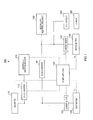
- FIG.1 is a block diagram showing the configuration of a power supply system that includes a vehicle power supply apparatus according to this embodiment.
- Power supply system 100 shown in FIG.1 has generator 110, two batteries (first battery 120 and second battery 130), two current sensors 122 and 132, two DC-DC converters 140 and 172, power supply ECU (Electronic Control Unit) 150, starter 160, starter relay 162, electrically driven compressor 170, and in-vehicle other general load (electrical equipment) 180.
- ECU Electrical Control Unit
- starter 160, starter relay 162, electrically driven compressor 170, and in-vehicle other general load (electrical equipment) 180 compose a power supply apparatus.
- starter 160, electrically driven compressor 170, and other general load (electrical equipment) 180 are referred to by the generic term "electrical load.”
- Generator 110 During vehicle deceleration, the rotation of the engine (not shown) is transferred to generator 110, which generates electric power and outputs regenerated energy electric power.
- Generator 110 is, for example, a large-capacity (for example, 150 A class) alternator with an IC regulator that is belt-driven by the engine and generates a voltage specified by power supply ECU 150 (for example, a 42 V voltage). It is also possible for generator 110 to be forcibly driven (caused to generate electric power) by means of power supply ECU 150 control as necessary other than during vehicle deceleration (forcible electric power generation).
- Generator 110 is connected to first battery 120 and two DC-DC converters 140 and 172.
- an alternator is used as generator 110, but this is not a limitation.
- a motor generator is provided with the functions of both a motor and a generator in a single unit.
- generator 110 may, for example, be connected by means of a transfer means such as a gear or belt or the like, or directly coupled, to an axle, crank axle, or the like, instead of being belt-driven by the engine.
- First battery 120 is connected to generator 110 and two DC-DC converters 140 and 172, recovers and stores regenerated energy generated by generator 110 during vehicle deceleration, and supplies electric power to electric loads (mainly electrically driven compressor 170 and general load 180) and second battery 130.
- first battery 120 should preferably be a high-voltage, high-performance battery with a large charging current and excellent chargeability.
- first battery 120 is a nickel-hydride battery, lithium-ion battery, or the like, and generates a high voltage (for example, 36 V) so as to enable efficient charging with regenerated energy.
- Using a high-voltage battery makes high-voltage charging possible, and enables regenerated energy recovery to be performed efficiently.
- First battery 120 functions as the main battery in this system, and, as explained later herein, it is an object of this embodiment to detect deterioration of this main battery (first battery 120).
- Second battery 130 is, for example, a general lead battery with a nominal voltage of 12 V, generates a voltage of 12 to 13 V, and supplies electric power to electrical loads (mainly starter 160 and general load 180). Second battery 130 receives and is charged with electric power supplied from generator 110 or first battery 120. Second battery 130 is connected to DC-DC converter 140, general load 180, and starter relay 162. Second battery 130 is not limited to a lead battery, and, for example, it is possible to use a nickel-hydride battery, lithium-ion battery, or the like instead of a lead battery.
- Current sensor 122 is a current sensor for measuring the charge/discharge current of first battery 120 in order to detect the state of first battery 120
- current sensor 132 is a current sensor for measuring the charge/discharge current of second battery 130 in order to detect the state of second battery 130.
- DC-DC converter 140 for example, steps down or steps up an input-side voltage in accordance with a switching operation of an internal power transistor, and supplies the resulting voltage to the output side.
- DC-DC converter 140 mainly functions as a step-down DC-DC converter that converts an input direct current voltage (an output voltage of generator 110 or an output voltage of first battery 120) to a different, lower direct current voltage, and outputs this lower direct current voltage.
- DC-DC converter 140 steps down an (input-side - that is, first battery 120-side) voltage of 36 V to an (output-side - that is, second battery 130-side) voltage of the order of 12 V.
- DC-DC converter 140 inputs a 36 V voltage as an input voltage and outputs a 12.5 to 14.5 V voltage as an output voltage.
- the output voltage of DC-DC converter 140 is controlled by power supply ECU 150.
- electric power is normally supplied to general load 180 with the output voltage of DC-DC converter 140 controlled at 12.5 V, but when second battery 130 is charged, the output voltage of DC-DC converter 140 is controlled at 14.5 V. That is to say, it is possible for the output voltage of DC-DC converter 140 to be controlled in the range of 12.5 to 14.5 V in order to perform second battery 130 charging control.
- DC-DC converter 172 mainly functions as a step-up DC-DC converter that converts an input direct current voltage (an output voltage of generator 110 or output voltage of first battery 120) to a different, higher direct current voltage, and outputs this higher direct current voltage. For example, if the rated voltage of electrically driven compressor 170 is 200 to 300 V, DC-DC converter 172 steps up a 36 V (input-side - that is, first battery 120-side) voltage to a 200 to 300 V (output-side - that is, electrically driven compressor 170-side) voltage. If a higher-voltage (for example, 200 to 300 V) battery is used as first battery 120, DC-DC converter 172 can be eliminated.
- Power supply ECU 150 performs overall control of the power supply system 100. Specifically, for example, power supply ECU 150 controls the on (started)/off (stopped) state and output voltage of each of DC-DC converters 140 and 172, and also controls the on (started)/off (stopped) state and output of electrically driven compressor 170. Also, power supply ECU 150 measures the voltage and charge/discharge current of each of batteries 120 and 130, and calculates state of charge (SOC) of each of batteries 120 and 130 by means of current integration. Furthermore, power supply ECU 150 controls generator 110. Moreover, power supply ECU 150 detects deterioration of first battery 120 by simultaneously measuring (sampling) the current and voltage of first battery 120 during discharging at predetermined timing and calculating the internal resistance.
- Power supply ECU 150 performs other controls described later herein. Details of power supply ECRU 150 control will be given later herein using flowcharts in FIG.3 onward.
- Power supply ECU 150 comprises a microcomputer, and more specifically, comprises, for example, a CPU (central processing unit), ROM (read only memory) that stores a program, and RAM (random access memory) for program execution.
- CPU central processing unit
- ROM read only memory
- RAM random access memory
- Starter 160 is a motor used when starting (cranking) the engine. Starter 160 is also used during driving to restart the engine from an idling stop state when the vehicle has stopped. Application of a current to starter 160 is performed by turning the ignition (IG) switch (not shown), which is the engine starting switch, to the engine start position (ST position) and turning on starter relay 162.
- IG ignition
- ST position engine start position
- Electrically driven compressor 170 is a compressor driven by an internal motor, and forms part of an air conditioner.
- the rated voltage of electrically driven compressor 170 is 200 to 300 V, for example, and it has the highest load among in-vehicle electrical loads.
- electrically driven compressor 170 having the highest load is used to create a situation in which battery deterioration can be detected with a high degree of accuracy. Since electrically driven compressor 170 is driven by electricity, in many cases it is used as a set together with a regenerative system having a battery that stores regenerated energy. In a system that does not use an electrically driven compressor, other high-load electrical equipment can be used instead of an electrically driven compressor. In a system that uses an electrically driven compressor, other high-load electrical equipment can of course be used together with the electrically driven compressor.
- General load 180 is, for example, a light or lamp, windshield wipers, audio equipment, a car navigation system, an air conditioner (excluding electrically driven compressor 170), or suchlike equipment installed in or on the vehicle.
- a regenerative system comprises a plurality of devices - for example, generator 110, first battery 120 that is the high-voltage main battery (a nickel-hydride battery or lithium-ion battery), step-down DC-DC converter 140, second battery 130 that is a general lead battery with a 12 V nominal voltage, and electrically driven compressor 170.
- generator 110 the high-voltage main battery (a nickel-hydride battery or lithium-ion battery)
- first battery 120 that is the high-voltage main battery (a nickel-hydride battery or lithium-ion battery)
- step-down DC-DC converter 140 the high-voltage main battery
- second battery 130 that is a general lead battery with a 12 V nominal voltage
- electrically driven compressor 170 electrically driven compressor
- deterioration of first battery 120 is detected with a high degree of accuracy by outputting (discharging) higher electric power from first battery 120 by controlling a plurality of devices (for example, electrically driven compressor 170/electrical equipment 180 and DC-DC converter 140), and at the same time actively (forcibly) creating a situation in which an electrical load is applied. Specifically, first, a situation is actively created for enabling deterioration of first battery 120 to be detected with a high degree of accuracy.
- the output voltage of DC-DC converter 140 is increased with the timing synchronized with the power consumption of electrically driven compressor 170 or electrical equipment 180, provision is made for electric power also to be supplied to second battery 130, and electric power output from first battery 120 is increased. Then, at the instant at which the electric power output from first battery 120 increases, the current and voltage of first battery 120 are simultaneously measured, the internal resistance of first battery 120 is calculated from the measurement results, and the deterioration of first battery 120 is detected.
- the timing at which the output voltage of DC-DC converter 140 is increased should be aligned with the timing of power consumption of electrically driven compressor 170 or electrical equipment 180, and when a condition for which drawing of a current from first battery 120 is predicted is satisfied, the output voltage of DC-DC converter 140 is increased in synchronization with this.
- a condition for which drawing of a current from first battery 120 is predicted is set beforehand by means of experimentation or the like, for example. Examples of such conditions are as shown in FIG.2 , for example,
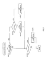
- FIG.3 is a main flowchart showing the overall operation of power supply system 100 in FIG.1
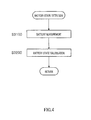
- FIG.4 is a flowchart showing the contents of the battery state detection processing in FIG.3
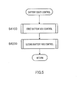
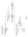
- FIG.5 is a flowcharts showing the contents of the battery state control processing in FIG.3
- FIG.6 is a flowchart showing the contents of the first battery SOC control processing in FIG.5
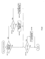
- FIG.7 is a flowchart showing the contents of the second battery SOC control processing in FIG.5
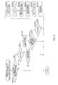
- FIG.8 is a flowchart showing the contents of the regenerative electric power generation control processing in FIG.3
- FIG.9 is a flowchart showing the contents of the DC-DC converter output control processing in FIG.8
- FIG.10 is a flowchart showing the contents of the discharge-time deterioration detection processing in FIG.3
- FIG.11 comprises schematic drawings for explaining the contents of the discharge-time
- step S1000 power supply ECU 150 determines whether or not the ignition (IG) switch (not shown) has been switched on. Specifically, if the ignition switch has been turned to the engine start position (ST position), power supply ECU 150 determines that the ignition switch has been switched on. If it is determined that the ignition switch has been switched on (S1000: YES), the processing flow proceeds to step S2000, whereas if it is determined that the ignition switch has not been switched on (S1000; NO), the program goes to a standby state,
- step S2000 power supply ECU 150 starts the engine, Specifically, power supply ECU 150 turns on starter relay 162 and applies a current to starter 160 from second battery 130. By this means, the engine starts.
- step S3000 power supply ECU 150 performs battery state detection processing.
- the contents of this battery state detection processing are as shown in the flowchart in FIG.4 .
- step S3100 power supply ECU 150 performs battery measurement. Specifically, power supply ECU 150 measures the first battery 120 current (I 1 ) and voltage (V 1 ), and also measures the second battery 130 current (I 2 ) and voltage (V 2 ). The first battery 120 current (I 1 ) is detected by current sensor 122, and the second battery 130 current (I 2 ) is detected by current sensor 132.
- step S3200 power supply ECU 150 performs battery state calculation. Specifically, for example, power supply ECU 150 performs current sensor 122 detection result (charge/discharge current value) integration and calculates the first battery 120 SOC (hereinafter referred to as "SOC1"), and performs current sensor 132 detection result (charge/discharge current value) integration and calculates the second battery 130 SOC (hereinafter referred to as "SOC2"). In this way, battery SOC calculation can be performed by integrating current flowing into a battery and current flowing out of the battery (so-called Coulomb count processing).
- the SOC calculation method for batteries 120 and 130 is not limited to Coulomb count processing, and any other known method can also be used. Following this, the control procedure returns to the main flowchart in FIG.3 .
- step S4000 power supply ECU 150 performs battery state control processing.
- this battery state control processing since batteries 120 and 130 will deteriorate more quickly if states of charge SOC1 and SOC2 of batteries 120 and 130 fall excessively, states of charge SOC1 and SOC2 of batteries 120 and 130 are controlled so as not to become less than or equal to a predetermined value.
- the contents of this battery state control processing are as shown in the flowchart in FIG.5 .
- step S4100 power supply ECU 150 performs first battery SOC control processing.
- state of charge SOC1 of first battery 120 is controlled within a fixed range.
- "a fixed range” is decided taking the characteristics of first battery 120 into consideration. For example, in the case of a lithium-ion battery, deterioration progresses more quickly if the SOC is too high or too low, and therefore a lithium-ion battery is normally used in a state in which the SOC is within an appropriate range (for example, 40 to 60%).
- step S4110 power supply ECU 150 determines whether or not generator 110 is performing forcible electric power generation. If it is determined that generator 110 is performing forcible electric power generation (S4110: YES), the processing flow proceeds to step S4120, whereas if it is determined that generator 110 is not performing forcible electric power generation (S4110: NO), the processing flow proceeds to step S4150.
- step S4120 power supply ECU 150 further determines whether or not state of charge SOC1 of first battery 120 is greater than or equal to 50%. If it is determined that state of charge SOC1 of first battery 120 is less than 50% (S4120: NO), the processing flow proceeds to step S4130, whereas if it is determined that state of charge SOC1 of first battery 120 is greater than or equal to 50% (S4120: YES), the processing flow proceeds to step S4140.
- step S4130 since state of charge SOC1 of first battery 120 is less than 50%, power supply ECU 150 continues forcible electric power generation by generator 110. By this means, first battery 120 is charged with electric power forcibly generated by generator 110. Following this, the control procedure proceeds to step S4150.
- step S4140 since state of charge SOC1 of first battery 120 is greater than or equal to 50%, power supply ECU 150 stops forcible electric power generation by generator 110 to leave a margin in charging by regenerated electric power. By this means, charging of first battery 120 with electric power forcibly generated by generator 110 is stopped. Following this, the control procedure proceeds to step S4150.
- step S4150 power supply ECU 150 determines whether or not state of charge SOC1 of first battery 120 is less than 45%, If it is determined that state of charge SOC1 of first battery 120 is less than 45% (S4150: YES), the processing flow proceeds to step S4160, whereas if it is determined that state of charge SOC1 of first battery 120 is greater than or equal to 45% (S4150: NO), the control procedure immediately returns to the flowchart in FIG.5 .
- step S4160 since state of charge SOC1 of first battery 120 has fallen below 45%, power supply ECU 150 starts forcible electric power generation by generator 110. By this means, first battery 120 is charged with electric power forcibly generated by generator 110. Following this, the control procedure returns to the flowchart in FIG.5 .
- step S4200 power supply ECU 150 performs second battery SOC control processing.
- state of charge SOC2 of second battery 130 is controlled within a fixed range.
- an on (started)/off (stopped) state of forcible charging from first battery 120 to second battery 130 is switched in a range in which state of charge SOC2 of second battery 130 is 90% or more and less than A% (normally 95%),
- This forcible charging on (started)/off (stopped) state is switched by controlling the output voltage of DC-DC converter 140,
- the contents of this second battery SOC control processing are as shown in the flowchart in FIG.7 .
- step S4210 power supply ECU 150 determines whether or not second battery 130 is being forcibly charged. If it is determined that second battery 130 is being forcibly charged (S4210: YES), the processing flow proceeds to step S4220, whereas if it is determined that second battery 130 is not being forcibly charged (S4210: NO), the processing flow proceeds to step S4250.
- step S4220 power supply ECU 150 further determines whether or not state of charge SOC2 of second battery 130 is greater than or equal to predetermined value A%.
- predetermined value A is normally set to 95 (%), for example.
- predetermined value A is set to 92 (%), and state of charge SOC2 of second battery 130 is consistently lowered somewhat.
- second battery 130 is placed in a state in which it is readily charged at any time (that is, in which the charging current is large), and a discharge current from first battery 120 at the time of deterioration detection of first battery 120 can be made larger.
- step S4220: NO If it is determined that state of charge SOC2 of second battery 130 is less than A% (S4220: NO), the processing flow proceeds to step S4230, whereas if it is determined that state of charge SOC2 of second battery 130 is greater than or equal to A% (S4220: YES), the processing flow proceeds to step S4240.
- step S4230 since state of charge SOC2 of second battery 130 is less than A%, power supply ECU 150 continues forcible charging from first battery 120 to second battery 130. That is to say, power supply ECU 150 keeps the output voltage of DC-DC converter 140 at 14.5 V. By this means, charging from first battery 120 to second battery 130 is forcibly performed. Following this, the control procedure proceeds to step S4250.
- step S4240 since state of charge SOC2 of second battery 130 is greater than or equal to A%, power supply ECU 150 stops forcible charging of second battery 130 from first battery 120 to leave a margin in charging by regenerated electric power. That is to say, power supply ECU 150 returns the output voltage of DC-DC converter 140 to 12.5 V. By this means, charging of second battery 130 from first battery 120 is stopped. Following this, the control procedure proceeds to step S4250.
- step S4250 power supply ECU 150 determines whether or not state of charge SOC2 of second battery 130 is less than 90%. If it is determined that state of charge SOC2 of second battery 130 is less than 90% (S4250: YES), the processing flow proceeds to step S4260, whereas if it is determined that state of charge SOC2 of second battery 130 is greater than or equal to 90% (S4250: NO), the control procedure immediately returns to the main flowchart in FIG.3 .
- step S4260 since state of charge SOC2 of second battery 130 has fallen below 90%, power supply ECU 150 starts forcible charging of second battery 130 from first battery 120. That is to say, power supply ECU 150 raises the output voltage of DC-DC converter 140 to 14.5 V. By this means, electric power is supplied to second battery 130 from first battery 120, and second battery 130 is forcibly charged with this electric power. Following this, the control procedure returns to the main flowchart in FIG.3 ,
- step S5000 power supply ECU 150 performs regenerative electric power generation control.
- the contents of this regenerative electric power generation control are as shown in the flowchart in FIG.8 .
- step S5100 power supply ECU 150 determines whether or not the vehicle speed is greater than or equal to a predetermined value (for example, 10 km/h) and the vehicle is decelerating.
- determining whether or not the vehicle speed is greater than or equal to a predetermined value is to determine whether or not the current vehicle speed is suitable for regenerative electric power generation -that is, whether or not kinetic energy necessary for regenerative electric power generation is available in the vehicle.
- Regenerated energy is obtained by converting kinetic energy of the vehicle to electrical energy, and if the vehicle speed is low, the kinetic energy is low. Thus, a regenerated energy amount cannot be expected.
- Whether or not the vehicle is decelerating is determined, for example, based on vehicle speed information, or based on the degree of brake pedal depression (whether the brake pedal is being depressed). If it is determined that the vehicle speed is greater than or equal to the predetermined value (10 km/h) and the vehicle is decelerating (S5100: YES), the processing flow proceeds to step S5200, and if this is not the case -that is, if the vehicle speed is less than the predetermined value (10 km/h) or the vehicle is not decelerating (that is, the vehicle is accelerating, traveling at a constant speed, idling, or the like) - (S5100: NO), the control procedure immediately returns to the main flowchart in FIG.3 .
- step S5200 power supply ECU 150 determines whether or not state of charge (SOC1) of first battery 120 is less than or equal to a predetermined value (for example, 55%). This predetermined value (55%) is the above upper limit. If it is determined that state of charge (SOC1) of first battery 120 exceeds the predetermined value (55%) (S5200: NO), the processing flow proceeds to step S5300, whereas if it is determined that state of charge (SOC1) of first battery 120 is less than or equal to the predetermined value (55%) (55200: YES), the processing flow proceeds to step 85400,
- step S5300 power supply ECU 150 stops electric power generation by generator 110. Following this, the control procedure returns to the main flowchart in FIG.3 .
- step 55400 power supply ECU 150 performs electric power generation control on generator 110. Specifically, power supply ECU 150 sets and outputs an output instruction value to generator 110 to a target value.
- a target value is a voltage necessary to charge first battery 120, and in the case of a 36 V lithium-ion battery, for example, this target value is 42 V.
- step S5500 power supply ECU 150 performs output control on DC-DC converter 140.
- the contents of this output control are as shown in the flowchart in FIG.9 .
- step S5510 power supply ECU 150 determines whether or not state of charge SOC2 of second battery 130 is less than 100%. If it is determined that state of charge SOC2 of second battery 130 is less than 100% (S5510: YES), the processing flow proceeds to step S5520, whereas if it is determined that state of charge SOC2 of second battery 130 is greater than or equal to 100% (S5510: NO), the processing flow proceeds to step S5530.
- step S6000 power supply ECU 150 performs discharge-time deterioration detection processing.
- This discharge-time deterioration detection processing is as shown in the flowchart in FIG.10 .
- step S6100 power supply ECU 150 determines whether or not drawing of a current from first battery 120 is predicted. This determination is made, for example, by determining whether or not a predetermined condition shown in FIG.2 is satisfied. For example, in the example shown in FIG.2 , with regard to electrically driven compressor 170, if the temperature inside the vehicle rises by a certain temperature (for example, 5°C) or more in a certain time (for example, one minute), it is predicted that the user will turn on the air conditioner (if the air conditioner is off) or increase the output of the air conditioner (if the air conditioner is on), and drawing of a current from first battery 120 occurs through the air conditioner actually being turned on or the air conditioner output actually being increased subsequently.
- a predetermined condition shown in FIG.2 For example, in the example shown in FIG.2 , with regard to electrically driven compressor 170, if the temperature inside the vehicle rises by a certain temperature (for example, 5°C) or more in a certain time (for example, one minute), it is predicted that the
- drawing of a current from first battery 120 is also predicted if a condition such as shown in Fig.2 is satisfied for electrical equipment 180 with comparatively high power consumption (such as headlights, power steering, brake lights, or windshield wipers, for example). If it is determined that drawing of a current from first battery 120 is predicted (S6100: YES), the processing flow proceeds to step S6200, whereas if it is determined that drawing of a current from first battery 120 is not predicted (S6100: NO), the control procedure immediately returns to the main flowchart in FIG.3 .
- step S6200 power supply ECU 150 further determines whether or not state of charge SOC2 of second battery 130 is less than or equal to 95%. The reason for this is to determine whether or not second battery 130 (a lead battery) is in a state in which it readily absorbs electric power (that is, readily receives a supply of electric power). If it is determined that state of charge SOC2 of second battery 130 is less than or equal to 95% (S6200: YES), the processing flow proceeds to step S6300, whereas if it is determined that state of charge SOC2 of second battery 130 exceeds 95% (S6200: NO), the control procedure immediately returns to the main flowchart in FIG.3 .
- step S6300 power supply ECU 150 performs output increase control of DC-DC converter 140. Specifically, power supply ECU 150 raises (increases) the output voltage of DC-DC converter 140 from the initial value (12.5 V) to 14.5 V.
- power supply ECU 150 raises (increases) the output voltage of DC-DC converter 140 from the initial value (12.5 V) to 14.5 V.
- electric power is supplied from first battery 120 not only to electrically driven compressor 170 or electrical equipment 180, but also to second battery 130, and supplying power to second battery 130 is started in line with (that is, in synchronization with) the timing of the start of power consumption by electrically driven compressor 170 or electrical equipment 180.
- a situation in which greater electric power is output (discharged) from first battery 120 is forcibly (actively) created.
- greater electric power (a larger current) is output when the output voltage of DC-DC converter 140 is increased in addition to driving of electrically driven compressor 170 than when only electrically driven compressor 170 is driven.
- step S6400 power supply ECU 150 performs simultaneous current and voltage measurement for first battery 120.
- power supply ECU 150 can simultaneously measure the current and voltage of first battery 120 at the instant at which electric power output from first battery 120 increases. The measurement of current and voltage is performed for at least two points.
- step S6500 power supply ECU 150 performs deterioration determination. Specifically, power supply ECU 150 calculates internal resistance r by means of equation 1 below, using the currents and voltages of a plurality of points measured in step S6400.
- Internal resistance r is one indicator of battery deterioration. For example, as shown schematically in FIG.11(B) , if current and voltage are taken as coordinate axes and measured currents and voltages of a plurality of points are plotted on the coordinate plane, the gradient of a linear approximation is internal resistance r. Solving equation 1 using measured values (-100 A, 30 V) and (-300 A, 28 V) of two points shown in FIG.11 gives a value of 0.01 ⁇ for internal resistance r.
- Power supply ECU 150 compares calculated internal resistance r with a predetermined determination value, and determines whether or not there is deterioration of first battery 120. The determination result is stored in a storage apparatus such as RAM, and is also reported to the user. Following this, the control procedure returns to the main flowchart in FIG.3 .
- step S7000 power supply ECU 150 determines whether or not the ignition (IG) switch has been switched off. If it is determined that the ignition switch has been switched off (S7000: YES), the processing flow proceeds to step S8000, whereas if it is determined that the ignition switch has not been switched off (S7000: NO), the processing flow returns to step S3000.
- IG ignition
- step S7000 power supply ECU 150 stops the engine. Specifically, power supply ECU 150 outputs a control signal that stops the engine to an engine ECU (not shown) that controls engine operation. By this means, the engine stops.
- greater electric power can be output (discharged) from first battery 120 by controlling a plurality of devices (for example, electrically driven compressor 170/electrical equipment 180 and DC-DC converter 140) and actively (forcibly) creating a situation in which an electrical load is applied simultaneously. Consequently, deterioration of first battery 120 can be detected with a high degree of accuracy.
- a plurality of devices for example, electrically driven compressor 170/electrical equipment 180 and DC-DC converter 140
- Embodiment 2 of the present invention battery deterioration detection at the time of charging will be described.
- the configuration of a power supply system of this embodiment is identical to the configuration of a power supply system that includes the vehicle power supply apparatus according to Embodiment 1 shown in FIG.1 .
- battery state control, regenerative electric power generation control, and battery deterioration detection by power supply ECU 150 differ from those in Embodiment 1.
- FIG.12 is a main flowchart showing the overall operation of the power supply system in FIG.1
- FIG.13 is a flowchart showing the contents of the battery state control processing in FIG.12
- FIG.14 is a flowchart showing the contents of the first battery SOC control processing in FIG.13
- FIG.15 is a flowchart showing the contents of the second battery SOC control processing in FIG.13
- FIG.16 is a flowchart showing the contents of the regenerative electric power generation control and charge-time deterioration detection processing in FIG.12
- FIG.17 comprises schematic drawings for explaining the contents of the charge-time deterioration detection processing in FIG.16 .
- Steps in FIG.12 common to FIG.2 are assigned the same reference signs as in FIG.2 , and detailed descriptions thereof are omitted here.
- the operations in S1000, S2000, S3000, S6000, and S7000 in FIG.12 are common to FIG.2 .
- step S4000A power supply ECU 150 performs battery state control processing.
- this battery state control processing since batteries 120 and 130 will deteriorate more quickly if states of charge SOC1 and SOC2 of batteries 120 and 130 fall excessively, states of charge SOC1 and SOC2 of batteries 120 and 130 are controlled so as not to become less than or equal to a predetermined value.
- the contents of this battery state control processing are as shown in the flowchart in FIG.13 .
- step S4100A power supply ECU 150 performs first battery SOC control processing.
- state of charge SOC1 of first battery 120 is controlled within a fixed range.
- a fixed range is decided taking the characteristics of first battery 120 into consideration. For example, in the case of a lithium-ion battery, deterioration progresses more quickly if the SOC is too high or too low, and hence a lithium-ion battery is normally used in a state in which the SOC is within an appropriate range (for example, 40 to 60%).
- first battery 120 is a lithium-ion battery
- on (started)/off (stopped) state of a forcible electric power generation of generator 110 is switched in a range in which state of charge SOC1 of first battery 120 is 45% or more and less than A% (normally 50%, for example).
- the contents of this first battery SOC control processing are as shown in the flowchart in FIG.14 .
- step 54110A power supply ECU 150 determines whether or not generator 110 is performing forcible electric power generation. If it is determined that generator 110 is performing forcible electric power generation (S4110A: YES), the processing flow proceeds to step S4120A, whereas if it is determined that generator 110 is not performing forcible electric power generation (S4110A: NO), the processing flow proceeds to step S4150A.
- step S4120A power supply ECU 150 further determines whether or not state of charge SOC1 of first battery 120 is greater than or equal to A%.
- predetermined value A is normally set to 50 (%), for example.
- step S4130A If it is determined that state of charge SOC1 of first battery 120 is less than A% (S4120A: NO), the processing flow proceeds to step S4130A, whereas if it is determined that state of charge SOC1 of first battery 120 is greater than or equal to A% (S4120A: YES), the processing flow proceeds to step S4140A.
- step S4130A since state of charge SOC1 of first battery 120 is less than A%, power supply ECU 150 continues forcible electric power generation by generator 110. By this means, first battery 120 is charged with electric power forcibly generated by generator 110. Following this, the control procedure proceeds to step S4150A.
- step S4140A since state of charge SOC1 of first battery 120 is greater than or equal to A%, power supply ECU 150 stops forcible electric power generation by generator 110 to leave a margin in charging by regenerated electric power. By this means, charging of first battery 120 with electric power forcibly generated by generator 110 is stopped. Following this, the control procedure proceeds to step S4150A.
- step S4150A power supply ECU 150 determines whether or not state of charge SOC1 of first battery 120 is less than 45%. If it is determined that state of charge SOC1 of first battery 120 is less than 45% (S4150A: YES), the processing flow proceeds to step S4160A, whereas if it is determined that state of charge SOC1 of first battery 120 is greater than or equal to 45% (S4150A: NO), the control procedure immediately returns to the flowchart in FIG.13 .
- step S4160A since state of charge SOC1 of first battery 120 has fallen below 45%, power supply ECU 150 starts forcible electric power generation by generator 110. By this means, first battery 120 is charged with electric power forcibly generated by generator 110. Following this, the control procedure returns to the flowchart in FIG. 13 .
- step S4200A power supply ECU 150 performs second battery SOC control processing.
- state of charge SOC2 of second battery 130 is controlled within a fixed range,
- an on (started)/off (stopped) state of forcible charging from first battery 120 to second battery 130 is switched in a range in which state of charge SOC2 of second battery 130 is 90% or more and less than 95%.
- This forcible charging on (started)/off (stopped) state is switched by controlling the output voltage of DC-DC converter 140.
- the contents of this second battery SOC control processing are as shown in the flowchart in FIG.15 .
- step S4210A power supply ECU 150 determines whether or not second battery 130 is being forcibly charged. If it is determined that second battery 130 is being forcibly charged (S4210A: YES), the processing flow proceeds to step S4220A, whereas if it is determined that second battery 130 is not being forcibly charged (S4210A: NO), the processing flow proceeds to step S4250A.
- step S4220A power supply ECU 150 further determines whether or not state of charge SOC2 of second battery 130 is greater than or equal to 95%. If it is determined that state of charge SOC2 of second battery 130 is less than 95% (S4220A: NO), the processing flow proceeds to step S4230A, whereas if it is determined that state of charge SOC2 of second battery 130 is greater than or equal to 95% (S4220A: YES), the processing flow proceeds to step S4240A.
- step S4230A since state of charge SOC2 of second battery 130 is less than 95%, power supply ECU 150 continues forcible charging from first battery 120 to second battery 130. That is to say, power supply ECU 150 keeps the output voltage of DC-DC converter 140 at 14.5 V. By this means, charging from first battery 120 to second battery 130 is forcibly performed. Following this, the control procedure proceeds to step S4250A.
- step S4240A since state of charge SOC2 of second battery 130 is greater than or equal to 95%, power supply ECU 150 stops forcible charging of second battery 130 from first battery 120 to leave a margin in charging by regenerated electric power. That is to say, power supply ECU 150 returns the output voltage of DC-DC converter 140 to 12.5 V. By this means, charging of second battery 130 from first battery 120 is stopped. Following this, the control procedure proceeds to step S4250A.
- step S4250A power supply ECU 150 determines whether or not state of charge SOC2 of second battery 130 is less than 90%. If it is determined that state of charge SOC2 of second battery 130 is less than 90% (S4250A: YES), the processing flow proceeds to step S4260A, whereas if it is determined that state of charge SOC2 of second battery 130 is greater than or equal to 90% (S4250A: NO), the control procedure immediately returns to the main flowchart in Fig.12 .
- step S4260A since state of charge SOC2 of second battery 130 has fallen below 90%, power supply ECU 150 starts forcible charging of second battery 130 from first battery 120. That is to say, power supply ECU 150 raises the output voltage of DC-DC converter 140 to 14.5 V. By this means, electric power is supplied to second battery 130 from first battery 120, and second battery 130 is forcibly charged with this electric power. Following this, the control procedure returns to the main flowchart in FIG.12 .
- step S5000A power supply ECU 150 performs regenerative electric power generation control and charge-time deterioration detection.
- the contents of this regenerative electric power generation control and charge-time deterioration detection are as shown in the flowchart in Fig.16 .
- step S5050A power supply ECU 150 determines whether or not the vehicle speed is greater than or equal to a predetermined value (for example, 10 km/h) and the vehicle is decelerating.
- determining whether or not the vehicle speed is greater than or equal to a predetermined value is to determine whether or not the current vehicle speed is suitable for regenerative electric power generation - that is, whether or not kinetic energy necessary for regenerative electric power generation is available in the vehicle.
- Regenerated energy is obtained by converting kinetic energy of the vehicle to electrical energy, and if the vehicle speed is low the kinetic energy is low. Thus, a regenerated energy amount cannot be expected.
- Whether or not the vehicle is decelerating is determined, for example, based on vehicle speed information, or based on the degree of brake pedal depression (whether the brake pedal is being depressed). If it is determined that the vehicle speed is greater than or equal to the predetermined value (10 km/h) and the vehicle is decelerating (S5050A: YES), the processing flow proceeds to step S5100A, and if this is not the case - that is, if the vehicle speed is less than the predetermined value (10 km/h) or the vehicle is not decelerating (that is, the vehicle is accelerating, traveling at a constant speed, idling, or the like) - (S5050A: NO), the control procedure immediately returns to the main flowchart in FIG.12 .
- step S5100A power supply ECU 150 determines whether or not state of charge (SOC1) of the first battery 120 is less than or equal to a predetermined value (for example, 55%). This predetermined value (55%) is the above upper limit. If it is determined that state of charge (SOC1) of first battery 120 exceeds the predetermined value (55%) (S5100A: NO), the processing flow proceeds to step S5150A, whereas if it is determined that state of charge (SOC1) of first battery 120 is less than or equal to the predetermined value (55%) (S5100A: YES), the processing flow proceeds to step S5200A.
- SOC1 state of charge
- step S5150A power supply ECU 150 stops electric power generation by generator 110. Following this, the control procedure returns to the main flowchart in FIG.12 .
- step S5200A power supply ECU 150 performs electric power generation control on generator 110. Specifically, power supply ECU 150 sets and outputs an output instruction value to generator 110 to a target value.
- a target value is a voltage necessary to charge first battery 120. In the case of a 36 V lithium-ion battery, for example, this target value is 42 V.
- step S5250A power supply ECU 150 determines whether or not regenerated electric power generated by generator 110 is greater than or equal to a predetermined value (for example, regenerated electric power of generated current of 100 A). If generated regenerated electric power is low, electric power with which first battery 120 is charged is also low, and accurate deterioration detection cannot be expected. Regenerated electric power generated by generator 110 depends on the vehicle speed. If it is determined that generated regenerated electric power is greater than or equal to the predetermined value (S5250A: YES), the processing flow proceeds to step S5300A, whereas if it is determined that generated regenerated electric power is less than the predetermined value (S5250A: NO), the control procedure immediately returns to the main flowchart in FIG.12 .
- a predetermined value for example, regenerated electric power of generated current of 100 A.
- step S5300A power supply ECU 150 determines whether or not state of charge SOC2 of second battery 130 is greater than or equal to 95%. The reason for this is to determine whether or not it is possible to supply electric power to electrical equipment 180 from second battery 130 when DC-DC converter 140 is temporarily stopped. If it is determined that state of charge SOC2 of second battery 130 is greater than or equal to 95% (S5300A: YES), the processing flow proceeds to step S5350A, whereas if it is determined that state of charge SOC2 of second battery 130 is less than 95% (S5300A: NO), the control procedure immediately returns to the main flowchart in FIG.12 .
- step S5350A power supply ECU 150 stops electrically driven compressor 170. By this means, supplying regenerated energy generated by generator 110 to electrically driven compressor 170 is stopped.
- step S5400A power supply ECU 150 stops DC-DC converter 140.
- supplying regenerated energy generated by generator 110 to electrical equipment 180 and second battery 130 is stopped. In this state, all regenerated energy generated by generator 110 is supplied to first battery 120.
- step S5450A power supply ECU 150 performs simultaneous current and voltage measurement for first battery 120.
- power supply ECU 150 can simultaneously measure the current and voltage of first battery 120 at the instant at which charging electric power to first battery 120 increases. The measurement of current and voltage is performed for at least two points.
- step S5500A power supply ECU 150 starts electrically driven compressor 170.
- step S5550A power supply ECU 150 starts DC-DC converter 140.
- step S5600A power supply ECU 150 performs deterioration determination. Specifically, power supply ECU 150 calculates internal resistance r by means of equation 1 below, using the currents and voltages of a plurality of points measured in step S5450A.
- Internal resistance r is one indicator of battery deterioration. For example, as shown schematically in FIG.17(B) , if current and voltage are taken as coordinate axes and measured currents and voltages of a plurality of points are plotted on the coordinate plane, the gradient of a linear approximation is internal resistance r. Solving equation 1 using measured values (50 A, 39 V) and (150 A, 40 V) of two points shown in FIG.17 gives a value of 0.01 ⁇ for internal resistance r.
- Power supply ECU 150 compares calculated internal resistance r with a predetermined determination value, and determines whether or not there is deterioration of first battery 120. The determination result is stored in a storage apparatus such as RAM, and is also reported to the user. Following this, the control procedure returns to the main flowchart in FIG.12 .
- first battery 120 can be charged in a concentrated fashion with regenerated energy generated by generator 110. Consequently, deterioration of first battery 120 can be detected with a high degree of accuracy.
- a vehicle power supply apparatus is suitable for use as a vehicle power supply apparatus that can further improve the accuracy of battery deterioration detection.
Landscapes
- Engineering & Computer Science (AREA)
- Power Engineering (AREA)
- Life Sciences & Earth Sciences (AREA)
- Sustainable Development (AREA)
- Sustainable Energy (AREA)
- Transportation (AREA)
- Mechanical Engineering (AREA)
- Electrochemistry (AREA)
- Manufacturing & Machinery (AREA)
- Chemical & Material Sciences (AREA)
- Chemical Kinetics & Catalysis (AREA)
- General Chemical & Material Sciences (AREA)
- General Physics & Mathematics (AREA)
- Physics & Mathematics (AREA)
- Charge And Discharge Circuits For Batteries Or The Like (AREA)
- Secondary Cells (AREA)
- Electric Propulsion And Braking For Vehicles (AREA)
Abstract
Description
- The present invention relates to a vehicle power supply apparatus used in a car or suchlike vehicle.
- In recent years, hybrid cars and electric cars have been attracting attention from an environmental protection viewpoint, and their development has progressed rapidly. These cars have a configuration whereby a driving force of driving the wheels is obtained by converting direct current electric power from a power supply having a secondary battery to alternating current electric power, and driving a motor by means of alternating current electric power. Normally, a hybrid car is an electric car that uses both an engine and a motor, and is a kind of electric car in a broad sense. Therefore, for convenience, in this specification the term "electric car" is used in a broad sense that includes a hybrid car unless specifically indicated otherwise.
- With an electric car of this kind, there is a particular demand for the accuracy of battery deterioration detection to be improved in order to correctly ascertain travel distance, battery life, and so forth.
- Conventionally, the apparatus described in
Patent Literature 1, for example, has been known as a vehicle battery deterioration determination apparatus. InPatent Literature 1,a technology is disclosed whereby when an electrical load connected to a battery is used, a voltage change of a battery voltage detected thereafter is calculated, and battery deterioration determination is performed by comparing the detected voltage change with a predetermined determination value. An electrical load is, for example, an air conditioner, power steering, headlights, brake lights, a radiator fan, or the like. Voltage change is calculated as a change in voltage over a predetermined time (that is, a voltage change trend) or a drop in battery voltage for the electrical load. By means of this configuration, the technology inPatent Literature 1 enables change over time of a battery to be detected accurately as battery deterioration, and the occurrence of starting trouble, stalling, or the like due to a low battery charge to be promptly reported to the driver. -
PTL 1
Japanese Patent Application Laid-Open No.2003-214248 - However, battery deterioration detection cannot be said to be performed accurately under better conditions with the above conventional battery deterioration determination apparatus. The reason for this is that with an air conditioner, power steering, headlights, or the like as an electrical load, the size of the load is limited to begin with. Consequently, a situation in which battery deterioration can be detected with a high degree of accuracy is not necessarily created merely by calculating a subsequent voltage change of a battery voltage when an electrical load of this kind is used. Therefore, there are certain limits to an improvement in the accuracy of battery deterioration detection.
- It is an object of the present invention to provide a vehicle power supply apparatus that can further improve the accuracy of battery deterioration detection.
- A vehicle power supply apparatus of the present invention has: a generator installed in a vehicle; a high-voltage first battery that is connected to the generator and stores electric power generated by the Generator; a DC-DC converter located between electrical equipment, and a node between the generator and the first battery; a second battery that is connected to the first battery via the DC-DC converter, and that has a lower voltage than the first battery; a control section that controls operation of the DC-DC converter so that electric power is supplied to the second battery from the first battery if a condition for which drawing of a current from the first battery is predicted is satisfied; a measurement section that measures a parameter necessary to detect deterioration of the first battery, in synchronization with a control operation on the DC-DC converter by the control section; and a determination section that determines deterioration of the first battery using a measurement result of the measurement section.
- The present invention can further improve the accuracy of battery deterioration detection
-
-
FIG.1 is a block diagram showing a configuration of a power supply system that includes a vehicle power supply apparatus according toEmbodiment 1 of the present invention; -
FIG.2 is a drawing showing examples of conditions for which drawing of a current from the first battery is predicted are satisfied in the power supply system inFIG.1 ; -
FIG.3 is a main flowchart showing the overall operation of the power supply system inFIG.1 ; -
FIG.4 is a flowchart showing the contents of the battery state detection processing inFig.3 ; -
FIG. 5 is a flowchart showing the contents of the battery state control processing inFIG.3 ; -
FIG.6 is a flowchart showing the contents of the first battery SOC control processing inFIG.5 ; -
FIG.7 is a flowchart showing the contents of the second battery SOC control processing inFIG.5 ; -
FIG.8 is a flowchart showing the contents of the regenerative electric power generation control processing inFIG.3 ; -
FIG.9 is a flowchart showing the contents of the DC-DC converter output control processing inFIG.8 ; -
FIG.10 is a flowchart showing the contents of the discharge-time deterioration detection processing inFIG.3 ; -
FIG.11 comprises schematic drawings for explaining the contents of the discharge-time deterioration detection processing inFIG.3 ; -
FIG.12 is a main flowchart showing the overall operation of a power supply system according to Embodiment 2 of the present invention; -
FIG.13 is a flowchart showing the contents of the battery state control processing inFIG.12 ; -
FIG.14 is a flowchart showing the contents of the first battery SOC control processing inFIG.13 ; -
FIG.15 is a flowchart showing the contents of the second battery SOC control processing inFIG.13 ; -
FIG.16 is a flowchart showing the contents of the regenerative electric power generation control and charge-time deterioration detection processing inFIG.12 ; and -
FIG.17 comprises schematic drawings for explaining the contents of the charge-time deterioration detection processing inFIG.16 . - Now, embodiments of the present invention will be described in detail using the accompanying drawings.
- In
Embodiment 1 of the present invention, battery deterioration detection at the time of discharging will be described.FIG.1 is a block diagram showing the configuration of a power supply system that includes a vehicle power supply apparatus according to this embodiment. -
Power supply system 100 shown inFIG.1 hasgenerator 110, two batteries (first battery 120 and second battery 130), twocurrent sensors DC converters starter 160,starter relay 162, electrically drivencompressor 170, and in-vehicle other general load (electrical equipment) 180. Of the above configuration elements, twobatteries current sensors DC converters starter 160, electrically drivencompressor 170, and other general load (electrical equipment) 180 are referred to by the generic term "electrical load." - During vehicle deceleration, the rotation of the engine (not shown) is transferred to
generator 110, which generates electric power and outputs regenerated energy electric power.Generator 110 is, for example, a large-capacity (for example, 150 A class) alternator with an IC regulator that is belt-driven by the engine and generates a voltage specified by power supply ECU 150 (for example, a 42 V voltage). It is also possible forgenerator 110 to be forcibly driven (caused to generate electric power) by means ofpower supply ECU 150 control as necessary other than during vehicle deceleration (forcible electric power generation).Generator 110 is connected tofirst battery 120 and two DC-DC converters - In this embodiment, an alternator is used as
generator 110, but this is not a limitation. For example, it is also possible to use a motor generator asgenerator 110 instead of an alternator. A motor generator is provided with the functions of both a motor and a generator in a single unit. Also,generator 110 may, for example, be connected by means of a transfer means such as a gear or belt or the like, or directly coupled, to an axle, crank axle, or the like, instead of being belt-driven by the engine. -
First battery 120 is connected togenerator 110 and two DC-DC converters generator 110 during vehicle deceleration, and supplies electric power to electric loads (mainly electrically drivencompressor 170 and general load 180) andsecond battery 130. In order to perform regenerated energy recovery efficiently,first battery 120 should preferably be a high-voltage, high-performance battery with a large charging current and excellent chargeability. For example,first battery 120 is a nickel-hydride battery, lithium-ion battery, or the like, and generates a high voltage (for example, 36 V) so as to enable efficient charging with regenerated energy. Using a high-voltage battery makes high-voltage charging possible, and enables regenerated energy recovery to be performed efficiently.First battery 120 functions as the main battery in this system, and, as explained later herein, it is an object of this embodiment to detect deterioration of this main battery (first battery 120). -
Second battery 130 is, for example, a general lead battery with a nominal voltage of 12 V, generates a voltage of 12 to 13 V, and supplies electric power to electrical loads (mainlystarter 160 and general load 180).Second battery 130 receives and is charged with electric power supplied fromgenerator 110 orfirst battery 120.Second battery 130 is connected to DC-DC converter 140,general load 180, andstarter relay 162.Second battery 130 is not limited to a lead battery, and, for example, it is possible to use a nickel-hydride battery, lithium-ion battery, or the like instead of a lead battery. -
Current sensor 122 is a current sensor for measuring the charge/discharge current offirst battery 120 in order to detect the state offirst battery 120, andcurrent sensor 132 is a current sensor for measuring the charge/discharge current ofsecond battery 130 in order to detect the state ofsecond battery 130. - DC-
DC converter 140, for example, steps down or steps up an input-side voltage in accordance with a switching operation of an internal power transistor, and supplies the resulting voltage to the output side. In this embodiment, DC-DC converter 140 mainly functions as a step-down DC-DC converter that converts an input direct current voltage (an output voltage ofgenerator 110 or an output voltage of first battery 120) to a different, lower direct current voltage, and outputs this lower direct current voltage. For example, DC-DC converter 140 steps down an (input-side - that is, first battery 120-side) voltage of 36 V to an (output-side - that is, second battery 130-side) voltage of the order of 12 V. More specifically, for example, DC-DC converter 140 inputs a 36 V voltage as an input voltage and outputs a 12.5 to 14.5 V voltage as an output voltage. The output voltage of DC-DC converter 140 is controlled bypower supply ECU 150. For example, electric power is normally supplied togeneral load 180 with the output voltage of DC-DC converter 140 controlled at 12.5 V, but whensecond battery 130 is charged, the output voltage of DC-DC converter 140 is controlled at 14.5 V. That is to say, it is possible for the output voltage of DC-DC converter 140 to be controlled in the range of 12.5 to 14.5 V in order to performsecond battery 130 charging control. - On the other hand, DC-
DC converter 172 mainly functions as a step-up DC-DC converter that converts an input direct current voltage (an output voltage ofgenerator 110 or output voltage of first battery 120) to a different, higher direct current voltage, and outputs this higher direct current voltage. For example, if the rated voltage of electrically drivencompressor 170 is 200 to 300 V, DC-DC converter 172 steps up a 36 V (input-side - that is, first battery 120-side) voltage to a 200 to 300 V (output-side - that is, electrically driven compressor 170-side) voltage. If a higher-voltage (for example, 200 to 300 V) battery is used asfirst battery 120, DC-DC converter 172 can be eliminated. -
Power supply ECU 150 performs overall control of thepower supply system 100. Specifically, for example,power supply ECU 150 controls the on (started)/off (stopped) state and output voltage of each of DC-DC converters compressor 170. Also,power supply ECU 150 measures the voltage and charge/discharge current of each ofbatteries batteries power supply ECU 150controls generator 110. Moreover,power supply ECU 150 detects deterioration offirst battery 120 by simultaneously measuring (sampling) the current and voltage offirst battery 120 during discharging at predetermined timing and calculating the internal resistance. In addition,power supply ECU 150 performs other controls described later herein. Details ofpower supply ECRU 150 control will be given later herein using flowcharts inFIG.3 onward.Power supply ECU 150 comprises a microcomputer, and more specifically, comprises, for example, a CPU (central processing unit), ROM (read only memory) that stores a program, and RAM (random access memory) for program execution. -
Starter 160 is a motor used when starting (cranking) the engine.Starter 160 is also used during driving to restart the engine from an idling stop state when the vehicle has stopped. Application of a current tostarter 160 is performed by turning the ignition (IG) switch (not shown), which is the engine starting switch, to the engine start position (ST position) and turning onstarter relay 162. - Electrically driven
compressor 170 is a compressor driven by an internal motor, and forms part of an air conditioner. The rated voltage of electrically drivencompressor 170 is 200 to 300 V, for example, and it has the highest load among in-vehicle electrical loads. In this embodiment, as described later herein, electrically drivencompressor 170 having the highest load is used to create a situation in which battery deterioration can be detected with a high degree of accuracy. Since electrically drivencompressor 170 is driven by electricity, in many cases it is used as a set together with a regenerative system having a battery that stores regenerated energy. In a system that does not use an electrically driven compressor, other high-load electrical equipment can be used instead of an electrically driven compressor. In a system that uses an electrically driven compressor, other high-load electrical equipment can of course be used together with the electrically driven compressor. -
General load 180 is, for example, a light or lamp, windshield wipers, audio equipment, a car navigation system, an air conditioner (excluding electrically driven compressor 170), or suchlike equipment installed in or on the vehicle. - In this embodiment, a regenerative system comprises a plurality of devices - for example,
generator 110,first battery 120 that is the high-voltage main battery (a nickel-hydride battery or lithium-ion battery), step-down DC-DC converter 140,second battery 130 that is a general lead battery with a 12 V nominal voltage, and electrically drivencompressor 170. - Also, in view of the fact that the larger an electrical load the more accurately battery deterioration can be detected, deterioration of
first battery 120 is detected with a high degree of accuracy by outputting (discharging) higher electric power fromfirst battery 120 by controlling a plurality of devices (for example, electrically drivencompressor 170/electrical equipment 180 and DC-DC converter 140), and at the same time actively (forcibly) creating a situation in which an electrical load is applied. Specifically, first, a situation is actively created for enabling deterioration offirst battery 120 to be detected with a high degree of accuracy. For example, when electrically drivencompressor 170 is turned on or its power consumption increases, or when electrical equipment (general load) 180, such as headlights, is turned on, the output voltage of DC-DC converter 140 is increased with the timing synchronized with the power consumption of electrically drivencompressor 170 orelectrical equipment 180, provision is made for electric power also to be supplied tosecond battery 130, and electric power output fromfirst battery 120 is increased. Then, at the instant at which the electric power output fromfirst battery 120 increases, the current and voltage offirst battery 120 are simultaneously measured, the internal resistance offirst battery 120 is calculated from the measurement results, and the deterioration offirst battery 120 is detected. - Here, the timing at which the output voltage of DC-
DC converter 140 is increased should be aligned with the timing of power consumption of electrically drivencompressor 170 orelectrical equipment 180, and when a condition for which drawing of a current fromfirst battery 120 is predicted is satisfied, the output voltage of DC-DC converter 140 is increased in synchronization with this. A condition for which drawing of a current fromfirst battery 120 is predicted is set beforehand by means of experimentation or the like, for example. Examples of such conditions are as shown inFIG.2 , for example, - Next, the operation of
power supply system 100 having the above configuration will be described usingFIG.3 through FIG.11 . Here,FIG.3 is a main flowchart showing the overall operation ofpower supply system 100 inFIG.1 ,FIG.4 is a flowchart showing the contents of the battery state detection processing inFIG.3 ,FIG.5 is a flowcharts showing the contents of the battery state control processing inFIG.3 ,FIG.6 is a flowchart showing the contents of the first battery SOC control processing inFIG.5 ,FIG.7 is a flowchart showing the contents of the second battery SOC control processing inFIG.5 ,FIG.8 is a flowchart showing the contents of the regenerative electric power generation control processing inFIG.3 ,FIG.9 is a flowchart showing the contents of the DC-DC converter output control processing inFIG.8 ,FIG.10 is a flowchart showing the contents of the discharge-time deterioration detection processing inFIG.3 , andFIG.11 comprises schematic drawings for explaining the contents of the discharge-time deterioration detection processing inFIG.3 . The flowcharts inFIG.3 through FIG.10 are stored as control programs in a storage apparatus such as ROM, and are executed by a CPU. - First, in step S1000,
power supply ECU 150 determines whether or not the ignition (IG) switch (not shown) has been switched on. Specifically, if the ignition switch has been turned to the engine start position (ST position),power supply ECU 150 determines that the ignition switch has been switched on. If it is determined that the ignition switch has been switched on (S1000: YES), the processing flow proceeds to step S2000, whereas if it is determined that the ignition switch has not been switched on (S1000; NO), the program goes to a standby state, - In step S2000,
power supply ECU 150 starts the engine, Specifically,power supply ECU 150 turns onstarter relay 162 and applies a current to starter 160 fromsecond battery 130. By this means, the engine starts. - In step S3000,
power supply ECU 150 performs battery state detection processing. The contents of this battery state detection processing are as shown in the flowchart inFIG.4 . - First, in step S3100,
power supply ECU 150 performs battery measurement. Specifically,power supply ECU 150 measures thefirst battery 120 current (I1) and voltage (V1), and also measures thesecond battery 130 current (I2) and voltage (V2). Thefirst battery 120 current (I1) is detected bycurrent sensor 122, and thesecond battery 130 current (I2) is detected bycurrent sensor 132. - Then, in step S3200,
power supply ECU 150 performs battery state calculation. Specifically, for example,power supply ECU 150 performscurrent sensor 122 detection result (charge/discharge current value) integration and calculates thefirst battery 120 SOC (hereinafter referred to as "SOC1"), and performscurrent sensor 132 detection result (charge/discharge current value) integration and calculates thesecond battery 130 SOC (hereinafter referred to as "SOC2"). In this way, battery SOC calculation can be performed by integrating current flowing into a battery and current flowing out of the battery (so-called Coulomb count processing). The SOC calculation method forbatteries FIG.3 . - In step S4000,
power supply ECU 150 performs battery state control processing. In this battery state control processing, sincebatteries batteries batteries FIG.5 . - First, in step S4100,
power supply ECU 150 performs first battery SOC control processing. In this first battery SOC control processing, state of charge SOC1 offirst battery 120 is controlled within a fixed range. Here, "a fixed range" is decided taking the characteristics offirst battery 120 into consideration. For example, in the case of a lithium-ion battery, deterioration progresses more quickly if the SOC is too high or too low, and therefore a lithium-ion battery is normally used in a state in which the SOC is within an appropriate range (for example, 40 to 60%). In this embodiment, the upper limit and lower limit are each narrowed by 5%, and state of charge SOC1 offirst battery 120 is controlled within a range of 45 to 55% (lower limit = 45%, upper limit = 55%). Also, for example, assuming a case in whichfirst battery 120 is a lithium-ion battery, in order to leave a margin in charging by regenerated electric power, a forcible electric power generation on (started)/off (stopped) state ofgenerator 110 is switched in a range in which state of charge SOC1 offirst battery 120 is 45% or more and less than 50%. The contents of this first battery SOC control processing are as shown in the flowchart inFIG.6 . - First, in step S4110,
power supply ECU 150 determines whether or notgenerator 110 is performing forcible electric power generation. If it is determined thatgenerator 110 is performing forcible electric power generation (S4110: YES), the processing flow proceeds to step S4120, whereas if it is determined thatgenerator 110 is not performing forcible electric power generation (S4110: NO), the processing flow proceeds to step S4150. - In step S4120,
power supply ECU 150 further determines whether or not state of charge SOC1 offirst battery 120 is greater than or equal to 50%. If it is determined that state of charge SOC1 offirst battery 120 is less than 50% (S4120: NO), the processing flow proceeds to step S4130, whereas if it is determined that state of charge SOC1 offirst battery 120 is greater than or equal to 50% (S4120: YES), the processing flow proceeds to step S4140. - In step S4130, since state of charge SOC1 of
first battery 120 is less than 50%,power supply ECU 150 continues forcible electric power generation bygenerator 110. By this means,first battery 120 is charged with electric power forcibly generated bygenerator 110. Following this, the control procedure proceeds to step S4150. - On the other hand, in step S4140, since state of charge SOC1 of
first battery 120 is greater than or equal to 50%,power supply ECU 150 stops forcible electric power generation bygenerator 110 to leave a margin in charging by regenerated electric power. By this means, charging offirst battery 120 with electric power forcibly generated bygenerator 110 is stopped. Following this, the control procedure proceeds to step S4150. - In step S4150,
power supply ECU 150 determines whether or not state of charge SOC1 offirst battery 120 is less than 45%, If it is determined that state of charge SOC1 offirst battery 120 is less than 45% (S4150: YES), the processing flow proceeds to step S4160, whereas if it is determined that state of charge SOC1 offirst battery 120 is greater than or equal to 45% (S4150: NO), the control procedure immediately returns to the flowchart inFIG.5 . - In step S4160, since state of charge SOC1 of
first battery 120 has fallen below 45%,power supply ECU 150 starts forcible electric power generation bygenerator 110. By this means,first battery 120 is charged with electric power forcibly generated bygenerator 110. Following this, the control procedure returns to the flowchart inFIG.5 . - Next, in step S4200,
power supply ECU 150 performs second battery SOC control processing. In this second battery SOC control processing, state of charge SOC2 ofsecond battery 130 is controlled within a fixed range. Here, "a fixed range" is decided taking the characteristics ofsecond battery 130 into consideration. For example, in the case of a lead battery, deterioration progresses more quickly the greater the fall in the SOC from a fully-charged (100%) state, and therefore a lead battery is normally used in a state close to a fully-charged state (SOC=100%). In this embodiment, for example, assuming a case in whichsecond battery 130 is a lead battery, in order to leave a margin in charging by regenerated electric power, an on (started)/off (stopped) state of forcible charging fromfirst battery 120 tosecond battery 130 is switched in a range in which state of charge SOC2 ofsecond battery 130 is 90% or more and less than A% (normally 95%), This forcible charging on (started)/off (stopped) state is switched by controlling the output voltage of DC-DC converter 140, The contents of this second battery SOC control processing are as shown in the flowchart inFIG.7 . - First, in step S4210,
power supply ECU 150 determines whether or notsecond battery 130 is being forcibly charged. If it is determined thatsecond battery 130 is being forcibly charged (S4210: YES), the processing flow proceeds to step S4220, whereas if it is determined thatsecond battery 130 is not being forcibly charged (S4210: NO), the processing flow proceeds to step S4250. - In step S4220,
power supply ECU 150 further determines whether or not state of charge SOC2 ofsecond battery 130 is greater than or equal to predetermined value A%. Here, "predetermined value A" is normally set to 95 (%), for example. However, when drawing of a current fromfirst battery 120 is predicted (seeFIG.2 ), for example, predetermined value A is set to 92 (%), and state of charge SOC2 ofsecond battery 130 is consistently lowered somewhat. By this means,second battery 130 is placed in a state in which it is readily charged at any time (that is, in which the charging current is large), and a discharge current fromfirst battery 120 at the time of deterioration detection offirst battery 120 can be made larger. If it is determined that state of charge SOC2 ofsecond battery 130 is less than A% (S4220: NO), the processing flow proceeds to step S4230, whereas if it is determined that state of charge SOC2 ofsecond battery 130 is greater than or equal to A% (S4220: YES), the processing flow proceeds to step S4240. - In step S4230, since state of charge SOC2 of
second battery 130 is less than A%,power supply ECU 150 continues forcible charging fromfirst battery 120 tosecond battery 130. That is to say,power supply ECU 150 keeps the output voltage of DC-DC converter 140 at 14.5 V. By this means, charging fromfirst battery 120 tosecond battery 130 is forcibly performed. Following this, the control procedure proceeds to step S4250. - On the other hand, in step S4240, since state of charge SOC2 of
second battery 130 is greater than or equal to A%,power supply ECU 150 stops forcible charging ofsecond battery 130 fromfirst battery 120 to leave a margin in charging by regenerated electric power. That is to say,power supply ECU 150 returns the output voltage of DC-DC converter 140 to 12.5 V. By this means, charging ofsecond battery 130 fromfirst battery 120 is stopped. Following this, the control procedure proceeds to step S4250. - In step S4250,
power supply ECU 150 determines whether or not state of charge SOC2 ofsecond battery 130 is less than 90%. If it is determined that state of charge SOC2 ofsecond battery 130 is less than 90% (S4250: YES), the processing flow proceeds to step S4260, whereas if it is determined that state of charge SOC2 ofsecond battery 130 is greater than or equal to 90% (S4250: NO), the control procedure immediately returns to the main flowchart inFIG.3 . - In step S4260, since state of charge SOC2 of
second battery 130 has fallen below 90%,power supply ECU 150 starts forcible charging ofsecond battery 130 fromfirst battery 120. That is to say,power supply ECU 150 raises the output voltage of DC-DC converter 140 to 14.5 V. By this means, electric power is supplied tosecond battery 130 fromfirst battery 120, andsecond battery 130 is forcibly charged with this electric power. Following this, the control procedure returns to the main flowchart inFIG.3 , - In step S5000,
power supply ECU 150 performs regenerative electric power generation control. The contents of this regenerative electric power generation control are as shown in the flowchart inFIG.8 . - First, in step S5100,
power supply ECU 150 determines whether or not the vehicle speed is greater than or equal to a predetermined value (for example, 10 km/h) and the vehicle is decelerating. Here, determining whether or not the vehicle speed is greater than or equal to a predetermined value is to determine whether or not the current vehicle speed is suitable for regenerative electric power generation -that is, whether or not kinetic energy necessary for regenerative electric power generation is available in the vehicle. Regenerated energy is obtained by converting kinetic energy of the vehicle to electrical energy, and if the vehicle speed is low, the kinetic energy is low. Thus, a regenerated energy amount cannot be expected. Whether or not the vehicle is decelerating is determined, for example, based on vehicle speed information, or based on the degree of brake pedal depression (whether the brake pedal is being depressed). If it is determined that the vehicle speed is greater than or equal to the predetermined value (10 km/h) and the vehicle is decelerating (S5100: YES), the processing flow proceeds to step S5200, and if this is not the case -that is, if the vehicle speed is less than the predetermined value (10 km/h) or the vehicle is not decelerating (that is, the vehicle is accelerating, traveling at a constant speed, idling, or the like) - (S5100: NO), the control procedure immediately returns to the main flowchart inFIG.3 . - In step S5200,
power supply ECU 150 determines whether or not state of charge (SOC1) offirst battery 120 is less than or equal to a predetermined value (for example, 55%). This predetermined value (55%) is the above upper limit. If it is determined that state of charge (SOC1) offirst battery 120 exceeds the predetermined value (55%) (S5200: NO), the processing flow proceeds to step S5300, whereas if it is determined that state of charge (SOC1) offirst battery 120 is less than or equal to the predetermined value (55%) (55200: YES), the processing flow proceeds to step 85400, - In step S5300,
power supply ECU 150 stops electric power generation bygenerator 110. Following this, the control procedure returns to the main flowchart inFIG.3 . - On the other hand, in step 55400,
power supply ECU 150 performs electric power generation control ongenerator 110. Specifically,power supply ECU 150 sets and outputs an output instruction value togenerator 110 to a target value. Here, a "target value" is a voltage necessary to chargefirst battery 120, and in the case of a 36 V lithium-ion battery, for example, this target value is 42 V. - Then in step S5500,
power supply ECU 150 performs output control on DC-DC converter 140. The contents of this output control are as shown in the flowchart inFIG.9 . - First, in step S5510,
power supply ECU 150 determines whether or not state of charge SOC2 ofsecond battery 130 is less than 100%. If it is determined that state of charge SOC2 ofsecond battery 130 is less than 100% (S5510: YES), the processing flow proceeds to step S5520, whereas if it is determined that state of charge SOC2 ofsecond battery 130 is greater than or equal to 100% (S5510: NO), the processing flow proceeds to step S5530. - In step S5520, since
second battery 130 is not in a fully-charged (SOC2 =100%) state,power supply ECU 150 raises the output voltage of DC-DC converter 140 to 14.5 V, higher than the initial value (12.5 V). By this means, regenerated electric power generated bygenerator 110 charges not onlyfirst battery 120 but alsosecond battery 130. Following this, the control procedure returns to the main flowchart inFIG.3 . - On the other hand, in step S5530, since
second battery 130 is in a fully-charged (SOC2=100%) state,power supply ECU 150 returns the output voltage of DC-DC converter 140 to the initial value (12.5 V). The reason for this is that a lead battery will deteriorate more quickly if excessively charged. Following this, the control procedure returns to the main flowchart inFIG.3 . - Next, in step S6000,
power supply ECU 150 performs discharge-time deterioration detection processing. This discharge-time deterioration detection processing is as shown in the flowchart inFIG.10 . - First, in step S6100,
power supply ECU 150 determines whether or not drawing of a current fromfirst battery 120 is predicted. This determination is made, for example, by determining whether or not a predetermined condition shown inFIG.2 is satisfied. For example, in the example shown inFIG.2 , with regard to electrically drivencompressor 170, if the temperature inside the vehicle rises by a certain temperature (for example, 5°C) or more in a certain time (for example, one minute), it is predicted that the user will turn on the air conditioner (if the air conditioner is off) or increase the output of the air conditioner (if the air conditioner is on), and drawing of a current fromfirst battery 120 occurs through the air conditioner actually being turned on or the air conditioner output actually being increased subsequently. Apart from electrically drivencompressor 170, drawing of a current fromfirst battery 120 is also predicted if a condition such as shown inFig.2 is satisfied forelectrical equipment 180 with comparatively high power consumption (such as headlights, power steering, brake lights, or windshield wipers, for example). If it is determined that drawing of a current fromfirst battery 120 is predicted (S6100: YES), the processing flow proceeds to step S6200, whereas if it is determined that drawing of a current fromfirst battery 120 is not predicted (S6100: NO), the control procedure immediately returns to the main flowchart inFIG.3 . - In step S6200,
power supply ECU 150 further determines whether or not state of charge SOC2 ofsecond battery 130 is less than or equal to 95%. The reason for this is to determine whether or not second battery 130 (a lead battery) is in a state in which it readily absorbs electric power (that is, readily receives a supply of electric power). If it is determined that state of charge SOC2 ofsecond battery 130 is less than or equal to 95% (S6200: YES), the processing flow proceeds to step S6300, whereas if it is determined that state of charge SOC2 ofsecond battery 130 exceeds 95% (S6200: NO), the control procedure immediately returns to the main flowchart inFIG.3 . - In step S6300,
power supply ECU 150 performs output increase control of DC-DC converter 140. Specifically,power supply ECU 150 raises (increases) the output voltage of DC-DC converter 140 from the initial value (12.5 V) to 14.5 V. By this means, electric power is supplied fromfirst battery 120 not only to electrically drivencompressor 170 orelectrical equipment 180, but also tosecond battery 130, and supplying power tosecond battery 130 is started in line with (that is, in synchronization with) the timing of the start of power consumption by electrically drivencompressor 170 orelectrical equipment 180. Thus, a situation in which greater electric power is output (discharged) fromfirst battery 120 is forcibly (actively) created. For example, as shown schematically inFIG.11 (A) , greater electric power (a larger current) is output when the output voltage of DC-DC converter 140 is increased in addition to driving of electrically drivencompressor 170 than when only electrically drivencompressor 170 is driven. - Then, in step S6400,
power supply ECU 150 performs simultaneous current and voltage measurement forfirst battery 120. At this time, as shown schematically inFIG.11(A) , for example,power supply ECU 150 can simultaneously measure the current and voltage offirst battery 120 at the instant at which electric power output fromfirst battery 120 increases. The measurement of current and voltage is performed for at least two points. - In step S6500,
power supply ECU 150 performs deterioration determination. Specifically,power supply ECU 150 calculates internal resistance r by means ofequation 1 below, using the currents and voltages of a plurality of points measured in step S6400. Internal resistance r is one indicator of battery deterioration. For example, as shown schematically inFIG.11(B) , if current and voltage are taken as coordinate axes and measured currents and voltages of a plurality of points are plotted on the coordinate plane, the gradient of a linear approximation is internal resistance r. Solvingequation 1 using measured values (-100 A, 30 V) and (-300 A, 28 V) of two points shown inFIG.11 gives a value of 0.01 Ω for internal resistance r. While solvingequation 1 for internal resistance r requires measurements for at least two points, measurements for three or more points may be used in order to improve the accuracy of deterioration determination.
where E: Electromotive force
r: Internal resistance
I: Current
V: Voltage -
Power supply ECU 150 compares calculated internal resistance r with a predetermined determination value, and determines whether or not there is deterioration offirst battery 120. The determination result is stored in a storage apparatus such as RAM, and is also reported to the user. Following this, the control procedure returns to the main flowchart inFIG.3 . - Next, in step S7000,
power supply ECU 150 determines whether or not the ignition (IG) switch has been switched off. If it is determined that the ignition switch has been switched off (S7000: YES), the processing flow proceeds to step S8000, whereas if it is determined that the ignition switch has not been switched off (S7000: NO), the processing flow returns to step S3000. - In step S7000,
power supply ECU 150 stops the engine. Specifically,power supply ECU 150 outputs a control signal that stops the engine to an engine ECU (not shown) that controls engine operation. By this means, the engine stops. - Thus, according to this embodiment, greater electric power can be output (discharged) from
first battery 120 by controlling a plurality of devices (for example, electrically drivencompressor 170/electrical equipment 180 and DC-DC converter 140) and actively (forcibly) creating a situation in which an electrical load is applied simultaneously. Consequently, deterioration offirst battery 120 can be detected with a high degree of accuracy. - In Embodiment 2 of the present invention, battery deterioration detection at the time of charging will be described. The configuration of a power supply system of this embodiment is identical to the configuration of a power supply system that includes the vehicle power supply apparatus according to
Embodiment 1 shown inFIG.1 . In this embodiment, battery state control, regenerative electric power generation control, and battery deterioration detection bypower supply ECU 150 differ from those inEmbodiment 1. - The operation of
power supply system 100 having the above configuration will now be described usingFIG.12 through FIG.17 . Here,FIG.12 is a main flowchart showing the overall operation of the power supply system inFIG.1 ,FIG.13 is a flowchart showing the contents of the battery state control processing inFIG.12 ,FIG.14 is a flowchart showing the contents of the first battery SOC control processing inFIG.13 ,FIG.15 is a flowchart showing the contents of the second battery SOC control processing inFIG.13 ,FIG.16 is a flowchart showing the contents of the regenerative electric power generation control and charge-time deterioration detection processing inFIG.12 , andFIG.17 comprises schematic drawings for explaining the contents of the charge-time deterioration detection processing inFIG.16 . - Steps in
FIG.12 common toFIG.2 are assigned the same reference signs as inFIG.2 , and detailed descriptions thereof are omitted here. The operations in S1000, S2000, S3000, S6000, and S7000 inFIG.12 are common toFIG.2 . - In step S4000A,
power supply ECU 150 performs battery state control processing. In this battery state control processing, sincebatteries batteries batteries FIG.13 . - First, in step S4100A,
power supply ECU 150 performs first battery SOC control processing. In this first battery SOC control processing, state of charge SOC1 offirst battery 120 is controlled within a fixed range. Here, "a fixed range" is decided taking the characteristics offirst battery 120 into consideration. For example, in the case of a lithium-ion battery, deterioration progresses more quickly if the SOC is too high or too low, and hence a lithium-ion battery is normally used in a state in which the SOC is within an appropriate range (for example, 40 to 60%). In this embodiment, the upper limit and lower limit are each narrowed by 5%, and state of charge SOC1 offirst battery 120 is controlled within a range of 45 to 55% (lower limit = 45%, upper limit = 55%). Also, for example, assuming a case in whichfirst battery 120 is a lithium-ion battery, in order to leave a margin in charging by regenerated electric power, on (started)/off (stopped) state of a forcible electric power generation ofgenerator 110 is switched in a range in which state of charge SOC1 offirst battery 120 is 45% or more and less than A% (normally 50%, for example). The contents of this first battery SOC control processing are as shown in the flowchart inFIG.14 . - First, in step 54110A,
power supply ECU 150 determines whether or notgenerator 110 is performing forcible electric power generation. If it is determined thatgenerator 110 is performing forcible electric power generation (S4110A: YES), the processing flow proceeds to step S4120A, whereas if it is determined thatgenerator 110 is not performing forcible electric power generation (S4110A: NO), the processing flow proceeds to step S4150A. - In step S4120A,
power supply ECU 150 further determines whether or not state of charge SOC1 offirst battery 120 is greater than or equal to A%. Here, "predetermined value A" is normally set to 50 (%), for example. However, since regenerated energy increases in proportion to an increase in vehicle speed, provision is made for the value of predetermined value A to be lowered in preparation for regenerated energy at the time of the next vehicle deceleration. For example, settings such as 50% for a vehicle speed of 60 km/h or less, 49% for a vehicle speed of 80 km/h or less, 48% for a vehicle speed of 100 km/h or less, and so forth, may be made. If it is determined that state of charge SOC1 offirst battery 120 is less than A% (S4120A: NO), the processing flow proceeds to step S4130A, whereas if it is determined that state of charge SOC1 offirst battery 120 is greater than or equal to A% (S4120A: YES), the processing flow proceeds to step S4140A. - In step S4130A, since state of charge SOC1 of
first battery 120 is less than A%,power supply ECU 150 continues forcible electric power generation bygenerator 110. By this means,first battery 120 is charged with electric power forcibly generated bygenerator 110. Following this, the control procedure proceeds to step S4150A. - On the other hand, in step S4140A, since state of charge SOC1 of
first battery 120 is greater than or equal to A%,power supply ECU 150 stops forcible electric power generation bygenerator 110 to leave a margin in charging by regenerated electric power. By this means, charging offirst battery 120 with electric power forcibly generated bygenerator 110 is stopped. Following this, the control procedure proceeds to step S4150A. - In step S4150A,
power supply ECU 150 determines whether or not state of charge SOC1 offirst battery 120 is less than 45%. If it is determined that state of charge SOC1 offirst battery 120 is less than 45% (S4150A: YES), the processing flow proceeds to step S4160A, whereas if it is determined that state of charge SOC1 offirst battery 120 is greater than or equal to 45% (S4150A: NO), the control procedure immediately returns to the flowchart inFIG.13 . - In step S4160A, since state of charge SOC1 of
first battery 120 has fallen below 45%,power supply ECU 150 starts forcible electric power generation bygenerator 110. By this means,first battery 120 is charged with electric power forcibly generated bygenerator 110. Following this, the control procedure returns to the flowchart inFIG. 13 . - Next, in step S4200A,
power supply ECU 150 performs second battery SOC control processing. In this second battery SOC control processing, state of charge SOC2 ofsecond battery 130 is controlled within a fixed range, Here, "a fixed range" is decided taking the characteristics ofsecond battery 130 into consideration. For example, in the case of a lead battery, the greater the fall in the SOC from a fully-charged (100%) state, the more quickly deterioration progresses, and therefore a lead battery is normally used in a state close to a fully-charged state (SOC=100%). In this embodiment, for example, assuming a case in whichsecond battery 130 is a lead battery, in order to leave a margin in charging by regenerated electric power, an on (started)/off (stopped) state of forcible charging fromfirst battery 120 tosecond battery 130 is switched in a range in which state of charge SOC2 ofsecond battery 130 is 90% or more and less than 95%. This forcible charging on (started)/off (stopped) state is switched by controlling the output voltage of DC-DC converter 140. The contents of this second battery SOC control processing are as shown in the flowchart inFIG.15 . - First, in step S4210A,
power supply ECU 150 determines whether or notsecond battery 130 is being forcibly charged. If it is determined thatsecond battery 130 is being forcibly charged (S4210A: YES), the processing flow proceeds to step S4220A, whereas if it is determined thatsecond battery 130 is not being forcibly charged (S4210A: NO), the processing flow proceeds to step S4250A. - In step S4220A,
power supply ECU 150 further determines whether or not state of charge SOC2 ofsecond battery 130 is greater than or equal to 95%. If it is determined that state of charge SOC2 ofsecond battery 130 is less than 95% (S4220A: NO), the processing flow proceeds to step S4230A, whereas if it is determined that state of charge SOC2 ofsecond battery 130 is greater than or equal to 95% (S4220A: YES), the processing flow proceeds to step S4240A. - In step S4230A, since state of charge SOC2 of
second battery 130 is less than 95%,power supply ECU 150 continues forcible charging fromfirst battery 120 tosecond battery 130. That is to say,power supply ECU 150 keeps the output voltage of DC-DC converter 140 at 14.5 V. By this means, charging fromfirst battery 120 tosecond battery 130 is forcibly performed. Following this, the control procedure proceeds to step S4250A. - . On the other hand, in step S4240A, since state of charge SOC2 of
second battery 130 is greater than or equal to 95%,power supply ECU 150 stops forcible charging ofsecond battery 130 fromfirst battery 120 to leave a margin in charging by regenerated electric power. That is to say,power supply ECU 150 returns the output voltage of DC-DC converter 140 to 12.5 V. By this means, charging ofsecond battery 130 fromfirst battery 120 is stopped. Following this, the control procedure proceeds to step S4250A. - In step S4250A,
power supply ECU 150 determines whether or not state of charge SOC2 ofsecond battery 130 is less than 90%. If it is determined that state of charge SOC2 ofsecond battery 130 is less than 90% (S4250A: YES), the processing flow proceeds to step S4260A, whereas if it is determined that state of charge SOC2 ofsecond battery 130 is greater than or equal to 90% (S4250A: NO), the control procedure immediately returns to the main flowchart inFig.12 . - In step S4260A, since state of charge SOC2 of
second battery 130 has fallen below 90%,power supply ECU 150 starts forcible charging ofsecond battery 130 fromfirst battery 120. That is to say,power supply ECU 150 raises the output voltage of DC-DC converter 140 to 14.5 V. By this means, electric power is supplied tosecond battery 130 fromfirst battery 120, andsecond battery 130 is forcibly charged with this electric power. Following this, the control procedure returns to the main flowchart inFIG.12 . - In step S5000A,
power supply ECU 150 performs regenerative electric power generation control and charge-time deterioration detection. The contents of this regenerative electric power generation control and charge-time deterioration detection are as shown in the flowchart inFig.16 . - First, in step S5050A,
power supply ECU 150 determines whether or not the vehicle speed is greater than or equal to a predetermined value (for example, 10 km/h) and the vehicle is decelerating. Here, determining whether or not the vehicle speed is greater than or equal to a predetermined value is to determine whether or not the current vehicle speed is suitable for regenerative electric power generation - that is, whether or not kinetic energy necessary for regenerative electric power generation is available in the vehicle. Regenerated energy is obtained by converting kinetic energy of the vehicle to electrical energy, and if the vehicle speed is low the kinetic energy is low. Thus, a regenerated energy amount cannot be expected. Whether or not the vehicle is decelerating is determined, for example, based on vehicle speed information, or based on the degree of brake pedal depression (whether the brake pedal is being depressed). If it is determined that the vehicle speed is greater than or equal to the predetermined value (10 km/h) and the vehicle is decelerating (S5050A: YES), the processing flow proceeds to step S5100A, and if this is not the case - that is, if the vehicle speed is less than the predetermined value (10 km/h) or the vehicle is not decelerating (that is, the vehicle is accelerating, traveling at a constant speed, idling, or the like) - (S5050A: NO), the control procedure immediately returns to the main flowchart inFIG.12 . - In step S5100A,
power supply ECU 150 determines whether or not state of charge (SOC1) of thefirst battery 120 is less than or equal to a predetermined value (for example, 55%). This predetermined value (55%) is the above upper limit. If it is determined that state of charge (SOC1) offirst battery 120 exceeds the predetermined value (55%) (S5100A: NO), the processing flow proceeds to step S5150A, whereas if it is determined that state of charge (SOC1) offirst battery 120 is less than or equal to the predetermined value (55%) (S5100A: YES), the processing flow proceeds to step S5200A. - In step S5150A,
power supply ECU 150 stops electric power generation bygenerator 110. Following this, the control procedure returns to the main flowchart inFIG.12 . - On the other hand, in step S5200A,
power supply ECU 150 performs electric power generation control ongenerator 110. Specifically,power supply ECU 150 sets and outputs an output instruction value togenerator 110 to a target value. Here, a "target value" is a voltage necessary to chargefirst battery 120. In the case of a 36 V lithium-ion battery, for example, this target value is 42 V. - Then, in step S5250A,
power supply ECU 150 determines whether or not regenerated electric power generated bygenerator 110 is greater than or equal to a predetermined value (for example, regenerated electric power of generated current of 100 A). If generated regenerated electric power is low, electric power with whichfirst battery 120 is charged is also low, and accurate deterioration detection cannot be expected. Regenerated electric power generated bygenerator 110 depends on the vehicle speed. If it is determined that generated regenerated electric power is greater than or equal to the predetermined value (S5250A: YES), the processing flow proceeds to step S5300A, whereas if it is determined that generated regenerated electric power is less than the predetermined value (S5250A: NO), the control procedure immediately returns to the main flowchart inFIG.12 . - In step S5300A,
power supply ECU 150 determines whether or not state of charge SOC2 ofsecond battery 130 is greater than or equal to 95%. The reason for this is to determine whether or not it is possible to supply electric power toelectrical equipment 180 fromsecond battery 130 when DC-DC converter 140 is temporarily stopped. If it is determined that state of charge SOC2 ofsecond battery 130 is greater than or equal to 95% (S5300A: YES), the processing flow proceeds to step S5350A, whereas if it is determined that state of charge SOC2 ofsecond battery 130 is less than 95% (S5300A: NO), the control procedure immediately returns to the main flowchart inFIG.12 . - In step S5350A,
power supply ECU 150 stops electrically drivencompressor 170. By this means, supplying regenerated energy generated bygenerator 110 to electrically drivencompressor 170 is stopped. - Then, in step S5400A,
power supply ECU 150 stops DC-DC converter 140. By this means, supplying regenerated energy generated bygenerator 110 toelectrical equipment 180 andsecond battery 130 is stopped. In this state, all regenerated energy generated bygenerator 110 is supplied tofirst battery 120. - Next, in step S5450A,
power supply ECU 150 performs simultaneous current and voltage measurement forfirst battery 120. At this time, as shown schematically inFIG.17(A) , for example,power supply ECU 150 can simultaneously measure the current and voltage offirst battery 120 at the instant at which charging electric power tofirst battery 120 increases. The measurement of current and voltage is performed for at least two points. - Then, in step S5500A,
power supply ECU 150 starts electrically drivencompressor 170. - Next, in step S5550A,
power supply ECU 150 starts DC-DC converter 140. - Then, in step S5600A,
power supply ECU 150 performs deterioration determination. Specifically,power supply ECU 150 calculates internal resistance r by means ofequation 1 below, using the currents and voltages of a plurality of points measured in step S5450A. Internal resistance r is one indicator of battery deterioration. For example, as shown schematically inFIG.17(B) , if current and voltage are taken as coordinate axes and measured currents and voltages of a plurality of points are plotted on the coordinate plane, the gradient of a linear approximation is internal resistance r. Solvingequation 1 using measured values (50 A, 39 V) and (150 A, 40 V) of two points shown inFIG.17 gives a value of 0.01 Ω for internal resistance r. While solvingequation 1 for internal resistance r requires measurements for at least two points, measurements for three or more points may be used in order to improve the accuracy of deterioration determination.
where E: Electromotive force
r: Internal resistance
I: Current
V: Voltage -
Power supply ECU 150 compares calculated internal resistance r with a predetermined determination value, and determines whether or not there is deterioration offirst battery 120. The determination result is stored in a storage apparatus such as RAM, and is also reported to the user. Following this, the control procedure returns to the main flowchart inFIG.12 . - Thus, according to this embodiment, during vehicle deceleration, the operation of other devices (for example, electrically driven
compressor 170, DC-DC converter 140, and so forth) can be temporarily stopped, andfirst battery 120 can be charged in a concentrated fashion with regenerated energy generated bygenerator 110. Consequently, deterioration offirst battery 120 can be detected with a high degree of accuracy. - In this embodiment, current and voltage are measured simultaneously and internal resistance is calculated as parameters for detecting battery deterioration, but the present invention is not limited to this. For example, provision may also be made for the gradient of voltage change or a drop in battery voltage to be calculated at the instant at which main battery output increases, using the method described in
Patent Literature 1. - The disclosures of Japanese Patent Application No.
2010-081978, filed on March 31, 2010 2010-081979, filed on March 31, 2010 - A vehicle power supply apparatus according to the present invention is suitable for use as a vehicle power supply apparatus that can further improve the accuracy of battery deterioration detection.
-
- 100 Power supply system
- 110 Generator
- 120, 130 Battery
- 122, 132 Current sensor
- 140, 172 DC-DC converter
- 150 Power supply ECU
- 160 Starter
- 162 Starter relay
- 170 Electrically driven compressor
- 180 General load (electrical equipment)
Claims (6)
- A vehicle power supply apparatus comprising:a generator installed in a vehicle;a high-voltage first battery that is connected to the generator and stores electric power generated by the generator;a DC-DC converter located between electrical equipment, and a node between the generator and the first battery;a second battery that is connected to the first battery via the DC-DC converter, and that has a lower voltage than the first battery;a control section that controls operation of the DC-DC converter;a measurement section that measures a parameter necessary to detect deterioration of the first battery, in synchronization with control of the DC-DC converter by the control section; anda determination section that determines deterioration of the first battery using a measurement result of the measurement section,wherein the control section increases an output voltage of the DC-DC converter if a condition for which drawing of a current from the first battery is predicted is satisfied, or temporarily stops the DC-DC converter during vehicle deceleration.
- The vehicle power supply apparatus according to claim 1, wherein:the first battery is a nickel-hydride battery, a lithium-ion battery, or a lead battery; and the second battery is a lead battery.
- The vehicle power supply apparatus according to claim 1, wherein:an electrically driven compressor is connected to the first battery; andthe condition for which drawing of a current from the first battery is predicted is satisfied is that the electrically driven compressor or the electrical equipment is turned on, or that power consumption of the electrically driven compressor increases.
- The vehicle power supply apparatus according to claim 1, wherein:an electrically driven compressor is connected to the first battery; andthe control section temporarily stops operation of the electrically driven compressor and the DC-DC converter during vehicle deceleration.
- The vehicle power supply apparatus according to claim 1,
wherein the measurement section measures a current and a voltage of a plurality of points for the first battery in synchronization with control of the DC-DC converter by the control section. - The vehicle power supply apparatus according to claim 5,
wherein the determination section calculates an internal resistance of the first battery using a measurement result of the measurement section, compares that internal resistance with a predetermined determination value, and determines deterioration of the first battery.
Applications Claiming Priority (3)
| Application Number | Priority Date | Filing Date | Title |
|---|---|---|---|
| JP2010081979 | 2010-03-31 | ||
| JP2010081978 | 2010-03-31 | ||
| PCT/JP2011/001819 WO2011121975A1 (en) | 2010-03-31 | 2011-03-28 | Power source device for vehicle |
Publications (3)
| Publication Number | Publication Date |
|---|---|
| EP2555372A1 true EP2555372A1 (en) | 2013-02-06 |
| EP2555372A4 EP2555372A4 (en) | 2018-01-24 |
| EP2555372B1 EP2555372B1 (en) | 2020-05-27 |
Family
ID=44711739
Family Applications (1)
| Application Number | Title | Priority Date | Filing Date |
|---|---|---|---|
| EP11762224.1A Active EP2555372B1 (en) | 2010-03-31 | 2011-03-28 | Power source device for vehicle |
Country Status (5)
| Country | Link |
|---|---|
| US (1) | US9071081B2 (en) |
| EP (1) | EP2555372B1 (en) |
| JP (1) | JP5799251B2 (en) |
| CN (1) | CN102823103B (en) |
| WO (1) | WO2011121975A1 (en) |
Cited By (4)
| Publication number | Priority date | Publication date | Assignee | Title |
|---|---|---|---|---|
| WO2015132626A1 (en) * | 2014-03-03 | 2015-09-11 | Robert Bosch (Sea) Pte. Ltd. | Hybird storage system |
| JP2016114584A (en) * | 2014-12-18 | 2016-06-23 | 株式会社デンソー | Battery degradation state determination device and battery degradation state determination method |
| EP3379681A4 (en) * | 2015-11-17 | 2018-12-26 | Omron Corporation | Charge/discharge control device, charge/discharge control system, and remaining-battery-capacity adjustment method |
| US10946750B2 (en) | 2015-11-17 | 2021-03-16 | Omron Corporation | Charge/discharge control device, charge/discharge control system, and charge/discharge control method |
Families Citing this family (23)
| Publication number | Priority date | Publication date | Assignee | Title |
|---|---|---|---|---|
| JP5293891B2 (en) * | 2010-06-18 | 2013-09-18 | トヨタ自動車株式会社 | Deterioration degree judging device |
| JP5772541B2 (en) * | 2011-11-24 | 2015-09-02 | トヨタ自動車株式会社 | Vehicle, power storage device diagnosis method, and diagnosis program |
| JP2014057423A (en) * | 2012-09-12 | 2014-03-27 | Hino Motors Ltd | Vehicle, generator system, and power generation method |
| JP6426002B2 (en) * | 2012-10-29 | 2018-11-21 | 三洋電機株式会社 | Power supply for vehicles |
| JP2014131369A (en) * | 2012-12-28 | 2014-07-10 | Kawasaki Heavy Ind Ltd | Power control system |
| US10480222B2 (en) * | 2013-03-29 | 2019-11-19 | Panasonic Intellectual Property Management Co., Ltd. | Door latching device and moving body mounted with same |
| JP6088355B2 (en) * | 2013-05-21 | 2017-03-01 | カルソニックカンセイ株式会社 | Battery status judgment device |
| JP6189105B2 (en) * | 2013-06-28 | 2017-08-30 | 三洋電機株式会社 | Power supply |
| US9969292B2 (en) * | 2014-11-14 | 2018-05-15 | Johnson Controls Technology Company | Semi-active partial parallel battery architecture for an automotive vehicle systems and methods |
| JP2016141356A (en) * | 2015-02-05 | 2016-08-08 | 株式会社オートネットワーク技術研究所 | Power supply device for automobile, and method for controlling the same |
| US9897661B2 (en) * | 2015-03-17 | 2018-02-20 | Microsoft Technology Licensing, Llc | Automatically determining a number of functioning batteries |
| CN106026649B (en) * | 2016-07-02 | 2019-02-12 | 深圳市华星光电技术有限公司 | DC-DC conversion circuit |
| JP6628699B2 (en) * | 2016-08-02 | 2020-01-15 | 株式会社デンソーテン | Power supply control device and power supply control system |
| JP6494115B2 (en) * | 2016-09-14 | 2019-04-03 | 本田技研工業株式会社 | Vehicle power supply |
| CN107128148A (en) * | 2017-04-21 | 2017-09-05 | 浙江吉利新能源商用车有限公司 | A kind of Independent air conditioning and warm wind work system |
| CN107196360A (en) * | 2017-05-15 | 2017-09-22 | 北京北交新能科技有限公司 | A kind of Brake energy recovery reutilization system for off-network tramcar |
| WO2020017168A1 (en) * | 2018-07-20 | 2020-01-23 | ボッシュ株式会社 | Power control device and power control method for hybrid vehicle |
| JP2020053176A (en) * | 2018-09-25 | 2020-04-02 | 株式会社デンソー | Battery monitoring system |
| KR102579181B1 (en) | 2018-10-22 | 2023-09-15 | 현대모비스 주식회사 | Dc converter capable of battery condition monitoring and battery condition monitoring method thereof |
| JP7067490B2 (en) * | 2019-01-07 | 2022-05-16 | トヨタ自動車株式会社 | Vehicle battery control device |
| WO2021054946A1 (en) * | 2019-09-18 | 2021-03-25 | General Electric Company | Direct current bus health analysis for a distributed generation system |
| JP7583234B2 (en) * | 2021-10-20 | 2024-11-14 | 株式会社クボタ | Battery Deterioration Diagnostic System |
| US20260031416A1 (en) * | 2024-07-26 | 2026-01-29 | Lithium Charging Concepts, Inc. | System for charging a house battery bank from an alternator |
Family Cites Families (24)
| Publication number | Priority date | Publication date | Assignee | Title |
|---|---|---|---|---|
| JP3736268B2 (en) * | 2000-03-21 | 2006-01-18 | 日産自動車株式会社 | Control device for hybrid vehicle |
| US6323608B1 (en) * | 2000-08-31 | 2001-11-27 | Honda Giken Kogyo Kabushiki Kaisha | Dual voltage battery for a motor vehicle |
| JP3566252B2 (en) * | 2001-12-12 | 2004-09-15 | 本田技研工業株式会社 | Hybrid vehicle and control method thereof |
| JP2003214248A (en) | 2002-01-28 | 2003-07-30 | Denso Corp | Vehicle battery deterioration determination device |
| JP3975798B2 (en) * | 2002-03-25 | 2007-09-12 | トヨタ自動車株式会社 | Abnormality detection apparatus and abnormality detection method for battery pack |
| EP1595748B1 (en) * | 2003-02-17 | 2012-09-12 | Denso Corporation | Vehicle power supply system |
| JP4360621B2 (en) * | 2004-02-09 | 2009-11-11 | 古河電気工業株式会社 | Secondary battery internal impedance measurement method, secondary battery internal impedance measurement device, secondary battery deterioration determination device, and power supply system |
| WO2005015252A1 (en) | 2003-06-27 | 2005-02-17 | The Furukawa Electric Co., Ltd. | Method for judging deterioration of accumulator, method for measuring secondary cell internal impedance, device for measuring secondary cell internal impedance, device for judging deterioration of secondary cell, and power source system |
| JP4038456B2 (en) | 2003-08-25 | 2008-01-23 | 株式会社豊田中央研究所 | Battery characteristic detection method |
| JP4774699B2 (en) * | 2004-07-28 | 2011-09-14 | 日産自動車株式会社 | Remaining capacity estimation device |
| JP4513494B2 (en) * | 2004-10-15 | 2010-07-28 | トヨタ自動車株式会社 | Control device and control method for voltage converter |
| JP2006333662A (en) * | 2005-05-27 | 2006-12-07 | Toyota Industries Corp | Apparatus and method for determining a deterioration state of a battery |
| JP4631761B2 (en) * | 2005-08-08 | 2011-02-16 | トヨタ自動車株式会社 | Battery life prediction device and battery life warning device for powertrain |
| JP4371100B2 (en) * | 2005-11-09 | 2009-11-25 | トヨタ自動車株式会社 | Battery condition diagnostic device |
| KR101025145B1 (en) | 2005-11-09 | 2011-03-31 | 도요타 지도샤(주) | Battery health diagnostic device |
| JP4589872B2 (en) * | 2006-01-04 | 2010-12-01 | 本田技研工業株式会社 | Control device for electric vehicle |
| JP2007245818A (en) * | 2006-03-14 | 2007-09-27 | Auto Network Gijutsu Kenkyusho:Kk | Battery state management system |
| JP4775707B2 (en) * | 2006-03-31 | 2011-09-21 | いすゞ自動車株式会社 | Energy regeneration device |
| JP2008278564A (en) * | 2007-04-25 | 2008-11-13 | Toyota Motor Corp | Power control device |
| JP2009042157A (en) * | 2007-08-10 | 2009-02-26 | Toyota Motor Corp | Electric vehicle, storage device deterioration detection method, and computer-readable recording medium storing a program for causing a computer to execute the deterioration detection method |
| JP2009274549A (en) * | 2008-05-14 | 2009-11-26 | Toyota Motor Corp | Electric power unit of vehicle |
| JP2010063267A (en) | 2008-09-03 | 2010-03-18 | Denso Corp | Power supply device |
| JP5357484B2 (en) | 2008-09-29 | 2013-12-04 | テルモ株式会社 | MEDICAL DEVICE, MEDICAL MATERIAL AND METHOD FOR PRODUCING THE SAME |
| JP2010081978A (en) | 2008-09-29 | 2010-04-15 | Terumo Corp | Transdermal administration positioning device |
-
2011
- 2011-03-28 EP EP11762224.1A patent/EP2555372B1/en active Active
- 2011-03-28 US US13/638,194 patent/US9071081B2/en active Active
- 2011-03-28 CN CN201180016059.4A patent/CN102823103B/en active Active
- 2011-03-28 JP JP2012508077A patent/JP5799251B2/en not_active Expired - Fee Related
- 2011-03-28 WO PCT/JP2011/001819 patent/WO2011121975A1/en not_active Ceased
Non-Patent Citations (1)
| Title |
|---|
| See references of WO2011121975A1 * |
Cited By (5)
| Publication number | Priority date | Publication date | Assignee | Title |
|---|---|---|---|---|
| WO2015132626A1 (en) * | 2014-03-03 | 2015-09-11 | Robert Bosch (Sea) Pte. Ltd. | Hybird storage system |
| JP2016114584A (en) * | 2014-12-18 | 2016-06-23 | 株式会社デンソー | Battery degradation state determination device and battery degradation state determination method |
| EP3379681A4 (en) * | 2015-11-17 | 2018-12-26 | Omron Corporation | Charge/discharge control device, charge/discharge control system, and remaining-battery-capacity adjustment method |
| US10919410B2 (en) | 2015-11-17 | 2021-02-16 | Omron Corporation | Charge/discharge control device, charge/discharge control system, and remaining battery capacity adjustment method |
| US10946750B2 (en) | 2015-11-17 | 2021-03-16 | Omron Corporation | Charge/discharge control device, charge/discharge control system, and charge/discharge control method |
Also Published As
| Publication number | Publication date |
|---|---|
| EP2555372A4 (en) | 2018-01-24 |
| CN102823103B (en) | 2015-03-11 |
| CN102823103A (en) | 2012-12-12 |
| US20130026828A1 (en) | 2013-01-31 |
| EP2555372B1 (en) | 2020-05-27 |
| JP5799251B2 (en) | 2015-10-21 |
| WO2011121975A1 (en) | 2011-10-06 |
| US9071081B2 (en) | 2015-06-30 |
| JPWO2011121975A1 (en) | 2013-07-04 |
Similar Documents
| Publication | Publication Date | Title |
|---|---|---|
| EP2555372B1 (en) | Power source device for vehicle | |
| US9956882B2 (en) | Electric power storage system | |
| JP5807180B2 (en) | Vehicle power supply | |
| US9086333B2 (en) | Examination system for electric vehicle or hybrid electric vehicle | |
| US11532841B2 (en) | Storage battery control device | |
| US9150106B2 (en) | Vehicle operating system and method of controlling the same | |
| US20140176085A1 (en) | Battery controller of vehicle | |
| US20140159670A1 (en) | Power control apparatus for vehicle battery | |
| US20060255766A1 (en) | Battery pack management method for HEV and EV | |
| CN111332297A (en) | A vehicle starting system and method based on intelligent management of low-voltage battery | |
| US20160161566A1 (en) | Method and system for online estimating internal resistance of battery | |
| EP2586663A1 (en) | Control device for vehicle and control method for vehicle | |
| US20110270489A1 (en) | Vehicle Electrical System | |
| US20170136914A1 (en) | Systems and methods for visualizing battery data | |
| US11198368B2 (en) | Vehicular charging control system | |
| US9365129B2 (en) | Vehicle having an electric motor and method of controlling a display displaying a cruising distance of the vehicle | |
| JP6186248B2 (en) | Inverter abnormality determination device | |
| JP2013189161A (en) | Hybrid vehicle and electric power supply method for hybrid vehicle | |
| JP2020192865A (en) | Vehicle power control device | |
| JP2015095917A (en) | Vehicle | |
| JP6189105B2 (en) | Power supply | |
| CN112649748A (en) | Method for determining the state of charge of a low-voltage battery of a motor vehicle | |
| CN117644834A (en) | Vehicle accessory load control and power stability |
Legal Events
| Date | Code | Title | Description |
|---|---|---|---|
| PUAI | Public reference made under article 153(3) epc to a published international application that has entered the european phase |
Free format text: ORIGINAL CODE: 0009012 |
|
| 17P | Request for examination filed |
Effective date: 20120928 |
|
| AK | Designated contracting states |
Kind code of ref document: A1 Designated state(s): AL AT BE BG CH CY CZ DE DK EE ES FI FR GB GR HR HU IE IS IT LI LT LU LV MC MK MT NL NO PL PT RO RS SE SI SK SM TR |
|
| DAX | Request for extension of the european patent (deleted) | ||
| RAP1 | Party data changed (applicant data changed or rights of an application transferred) |
Owner name: PANASONIC INTELLECTUAL PROPERTY MANAGEMENT CO., LT |
|
| RAP1 | Party data changed (applicant data changed or rights of an application transferred) |
Owner name: PANASONIC INTELLECTUAL PROPERTY MANAGEMENT CO., LT |
|
| RA4 | Supplementary search report drawn up and despatched (corrected) |
Effective date: 20180102 |
|
| RIC1 | Information provided on ipc code assigned before grant |
Ipc: H02J 7/00 20060101AFI20171219BHEP Ipc: G01R 31/36 20060101ALN20171219BHEP Ipc: B60R 16/04 20060101ALI20171219BHEP Ipc: B60L 11/18 20060101ALI20171219BHEP Ipc: H01M 10/0525 20100101ALN20171219BHEP Ipc: H01M 10/48 20060101ALN20171219BHEP Ipc: H01M 10/34 20060101ALN20171219BHEP Ipc: H02J 7/14 20060101ALN20171219BHEP |
|
| REG | Reference to a national code |
Ref country code: DE Ref legal event code: R079 Ref document number: 602011067038 Country of ref document: DE Free format text: PREVIOUS MAIN CLASS: H02J0007000000 Ipc: B60R0016040000 |
|
| GRAP | Despatch of communication of intention to grant a patent |
Free format text: ORIGINAL CODE: EPIDOSNIGR1 |
|
| STAA | Information on the status of an ep patent application or granted ep patent |
Free format text: STATUS: GRANT OF PATENT IS INTENDED |
|
| RIC1 | Information provided on ipc code assigned before grant |
Ipc: B60L 58/20 20190101ALI20200122BHEP Ipc: H01M 10/48 20060101ALN20200122BHEP Ipc: H01M 10/34 20060101ALN20200122BHEP Ipc: H01M 10/0525 20100101ALN20200122BHEP Ipc: B60L 58/16 20190101ALI20200122BHEP Ipc: H02J 7/14 20060101ALN20200122BHEP Ipc: B60R 16/04 20060101AFI20200122BHEP Ipc: G01R 31/392 20190101ALI20200122BHEP |
|
| RIC1 | Information provided on ipc code assigned before grant |
Ipc: H02J 7/14 20060101ALN20200127BHEP Ipc: B60L 58/16 20190101ALI20200127BHEP Ipc: H01M 10/34 20060101ALN20200127BHEP Ipc: H01M 10/0525 20100101ALN20200127BHEP Ipc: H01M 10/48 20060101ALN20200127BHEP Ipc: B60L 58/20 20190101ALI20200127BHEP Ipc: B60R 16/04 20060101AFI20200127BHEP Ipc: G01R 31/392 20190101ALI20200127BHEP |
|
| INTG | Intention to grant announced |
Effective date: 20200211 |
|
| GRAS | Grant fee paid |
Free format text: ORIGINAL CODE: EPIDOSNIGR3 |
|
| GRAA | (expected) grant |
Free format text: ORIGINAL CODE: 0009210 |
|
| STAA | Information on the status of an ep patent application or granted ep patent |
Free format text: STATUS: THE PATENT HAS BEEN GRANTED |
|
| AK | Designated contracting states |
Kind code of ref document: B1 Designated state(s): AL AT BE BG CH CY CZ DE DK EE ES FI FR GB GR HR HU IE IS IT LI LT LU LV MC MK MT NL NO PL PT RO RS SE SI SK SM TR |
|
| REG | Reference to a national code |
Ref country code: GB Ref legal event code: FG4D |
|
| REG | Reference to a national code |
Ref country code: CH Ref legal event code: EP |
|
| REG | Reference to a national code |
Ref country code: AT Ref legal event code: REF Ref document number: 1274235 Country of ref document: AT Kind code of ref document: T Effective date: 20200615 |
|
| REG | Reference to a national code |
Ref country code: DE Ref legal event code: R096 Ref document number: 602011067038 Country of ref document: DE |
|
| REG | Reference to a national code |
Ref country code: LT Ref legal event code: MG4D |
|
| PG25 | Lapsed in a contracting state [announced via postgrant information from national office to epo] |
Ref country code: LT Free format text: LAPSE BECAUSE OF FAILURE TO SUBMIT A TRANSLATION OF THE DESCRIPTION OR TO PAY THE FEE WITHIN THE PRESCRIBED TIME-LIMIT Effective date: 20200527 Ref country code: NO Free format text: LAPSE BECAUSE OF FAILURE TO SUBMIT A TRANSLATION OF THE DESCRIPTION OR TO PAY THE FEE WITHIN THE PRESCRIBED TIME-LIMIT Effective date: 20200827 Ref country code: FI Free format text: LAPSE BECAUSE OF FAILURE TO SUBMIT A TRANSLATION OF THE DESCRIPTION OR TO PAY THE FEE WITHIN THE PRESCRIBED TIME-LIMIT Effective date: 20200527 Ref country code: GR Free format text: LAPSE BECAUSE OF FAILURE TO SUBMIT A TRANSLATION OF THE DESCRIPTION OR TO PAY THE FEE WITHIN THE PRESCRIBED TIME-LIMIT Effective date: 20200828 Ref country code: PT Free format text: LAPSE BECAUSE OF FAILURE TO SUBMIT A TRANSLATION OF THE DESCRIPTION OR TO PAY THE FEE WITHIN THE PRESCRIBED TIME-LIMIT Effective date: 20200928 Ref country code: SE Free format text: LAPSE BECAUSE OF FAILURE TO SUBMIT A TRANSLATION OF THE DESCRIPTION OR TO PAY THE FEE WITHIN THE PRESCRIBED TIME-LIMIT Effective date: 20200527 Ref country code: IS Free format text: LAPSE BECAUSE OF FAILURE TO SUBMIT A TRANSLATION OF THE DESCRIPTION OR TO PAY THE FEE WITHIN THE PRESCRIBED TIME-LIMIT Effective date: 20200927 |
|
| REG | Reference to a national code |
Ref country code: NL Ref legal event code: MP Effective date: 20200527 |
|
| PG25 | Lapsed in a contracting state [announced via postgrant information from national office to epo] |
Ref country code: HR Free format text: LAPSE BECAUSE OF FAILURE TO SUBMIT A TRANSLATION OF THE DESCRIPTION OR TO PAY THE FEE WITHIN THE PRESCRIBED TIME-LIMIT Effective date: 20200527 Ref country code: BG Free format text: LAPSE BECAUSE OF FAILURE TO SUBMIT A TRANSLATION OF THE DESCRIPTION OR TO PAY THE FEE WITHIN THE PRESCRIBED TIME-LIMIT Effective date: 20200827 Ref country code: LV Free format text: LAPSE BECAUSE OF FAILURE TO SUBMIT A TRANSLATION OF THE DESCRIPTION OR TO PAY THE FEE WITHIN THE PRESCRIBED TIME-LIMIT Effective date: 20200527 Ref country code: RS Free format text: LAPSE BECAUSE OF FAILURE TO SUBMIT A TRANSLATION OF THE DESCRIPTION OR TO PAY THE FEE WITHIN THE PRESCRIBED TIME-LIMIT Effective date: 20200527 |
|
| REG | Reference to a national code |
Ref country code: AT Ref legal event code: MK05 Ref document number: 1274235 Country of ref document: AT Kind code of ref document: T Effective date: 20200527 |
|
| PG25 | Lapsed in a contracting state [announced via postgrant information from national office to epo] |
Ref country code: AL Free format text: LAPSE BECAUSE OF FAILURE TO SUBMIT A TRANSLATION OF THE DESCRIPTION OR TO PAY THE FEE WITHIN THE PRESCRIBED TIME-LIMIT Effective date: 20200527 Ref country code: NL Free format text: LAPSE BECAUSE OF FAILURE TO SUBMIT A TRANSLATION OF THE DESCRIPTION OR TO PAY THE FEE WITHIN THE PRESCRIBED TIME-LIMIT Effective date: 20200527 |
|
| PG25 | Lapsed in a contracting state [announced via postgrant information from national office to epo] |
Ref country code: SM Free format text: LAPSE BECAUSE OF FAILURE TO SUBMIT A TRANSLATION OF THE DESCRIPTION OR TO PAY THE FEE WITHIN THE PRESCRIBED TIME-LIMIT Effective date: 20200527 Ref country code: IT Free format text: LAPSE BECAUSE OF FAILURE TO SUBMIT A TRANSLATION OF THE DESCRIPTION OR TO PAY THE FEE WITHIN THE PRESCRIBED TIME-LIMIT Effective date: 20200527 Ref country code: EE Free format text: LAPSE BECAUSE OF FAILURE TO SUBMIT A TRANSLATION OF THE DESCRIPTION OR TO PAY THE FEE WITHIN THE PRESCRIBED TIME-LIMIT Effective date: 20200527 Ref country code: CZ Free format text: LAPSE BECAUSE OF FAILURE TO SUBMIT A TRANSLATION OF THE DESCRIPTION OR TO PAY THE FEE WITHIN THE PRESCRIBED TIME-LIMIT Effective date: 20200527 Ref country code: RO Free format text: LAPSE BECAUSE OF FAILURE TO SUBMIT A TRANSLATION OF THE DESCRIPTION OR TO PAY THE FEE WITHIN THE PRESCRIBED TIME-LIMIT Effective date: 20200527 Ref country code: ES Free format text: LAPSE BECAUSE OF FAILURE TO SUBMIT A TRANSLATION OF THE DESCRIPTION OR TO PAY THE FEE WITHIN THE PRESCRIBED TIME-LIMIT Effective date: 20200527 Ref country code: AT Free format text: LAPSE BECAUSE OF FAILURE TO SUBMIT A TRANSLATION OF THE DESCRIPTION OR TO PAY THE FEE WITHIN THE PRESCRIBED TIME-LIMIT Effective date: 20200527 Ref country code: DK Free format text: LAPSE BECAUSE OF FAILURE TO SUBMIT A TRANSLATION OF THE DESCRIPTION OR TO PAY THE FEE WITHIN THE PRESCRIBED TIME-LIMIT Effective date: 20200527 |
|
| PG25 | Lapsed in a contracting state [announced via postgrant information from national office to epo] |
Ref country code: SK Free format text: LAPSE BECAUSE OF FAILURE TO SUBMIT A TRANSLATION OF THE DESCRIPTION OR TO PAY THE FEE WITHIN THE PRESCRIBED TIME-LIMIT Effective date: 20200527 Ref country code: PL Free format text: LAPSE BECAUSE OF FAILURE TO SUBMIT A TRANSLATION OF THE DESCRIPTION OR TO PAY THE FEE WITHIN THE PRESCRIBED TIME-LIMIT Effective date: 20200527 |
|
| REG | Reference to a national code |
Ref country code: DE Ref legal event code: R097 Ref document number: 602011067038 Country of ref document: DE |
|
| PLBE | No opposition filed within time limit |
Free format text: ORIGINAL CODE: 0009261 |
|
| STAA | Information on the status of an ep patent application or granted ep patent |
Free format text: STATUS: NO OPPOSITION FILED WITHIN TIME LIMIT |
|
| 26N | No opposition filed |
Effective date: 20210302 |
|
| PG25 | Lapsed in a contracting state [announced via postgrant information from national office to epo] |
Ref country code: SI Free format text: LAPSE BECAUSE OF FAILURE TO SUBMIT A TRANSLATION OF THE DESCRIPTION OR TO PAY THE FEE WITHIN THE PRESCRIBED TIME-LIMIT Effective date: 20200527 |
|
| PG25 | Lapsed in a contracting state [announced via postgrant information from national office to epo] |
Ref country code: MC Free format text: LAPSE BECAUSE OF FAILURE TO SUBMIT A TRANSLATION OF THE DESCRIPTION OR TO PAY THE FEE WITHIN THE PRESCRIBED TIME-LIMIT Effective date: 20200527 |
|
| REG | Reference to a national code |
Ref country code: CH Ref legal event code: PL |
|
| GBPC | Gb: european patent ceased through non-payment of renewal fee |
Effective date: 20210328 |
|
| REG | Reference to a national code |
Ref country code: BE Ref legal event code: MM Effective date: 20210331 |
|
| PG25 | Lapsed in a contracting state [announced via postgrant information from national office to epo] |
Ref country code: CH Free format text: LAPSE BECAUSE OF NON-PAYMENT OF DUE FEES Effective date: 20210331 Ref country code: LI Free format text: LAPSE BECAUSE OF NON-PAYMENT OF DUE FEES Effective date: 20210331 Ref country code: LU Free format text: LAPSE BECAUSE OF NON-PAYMENT OF DUE FEES Effective date: 20210328 Ref country code: IE Free format text: LAPSE BECAUSE OF NON-PAYMENT OF DUE FEES Effective date: 20210328 Ref country code: GB Free format text: LAPSE BECAUSE OF NON-PAYMENT OF DUE FEES Effective date: 20210328 Ref country code: FR Free format text: LAPSE BECAUSE OF NON-PAYMENT OF DUE FEES Effective date: 20210331 |
|
| PG25 | Lapsed in a contracting state [announced via postgrant information from national office to epo] |
Ref country code: BE Free format text: LAPSE BECAUSE OF NON-PAYMENT OF DUE FEES Effective date: 20210331 |
|
| PG25 | Lapsed in a contracting state [announced via postgrant information from national office to epo] |
Ref country code: HU Free format text: LAPSE BECAUSE OF FAILURE TO SUBMIT A TRANSLATION OF THE DESCRIPTION OR TO PAY THE FEE WITHIN THE PRESCRIBED TIME-LIMIT; INVALID AB INITIO Effective date: 20110328 Ref country code: CY Free format text: LAPSE BECAUSE OF FAILURE TO SUBMIT A TRANSLATION OF THE DESCRIPTION OR TO PAY THE FEE WITHIN THE PRESCRIBED TIME-LIMIT Effective date: 20200527 |
|
| REG | Reference to a national code |
Ref country code: DE Ref legal event code: R081 Ref document number: 602011067038 Country of ref document: DE Owner name: PANASONIC AUTOMOTIVE SYSTEMS CO., LTD., YOKOHA, JP Free format text: FORMER OWNER: PANASONIC INTELLECTUAL PROPERTY MANAGEMENT CO., LTD., OSAKA, JP |
|
| PG25 | Lapsed in a contracting state [announced via postgrant information from national office to epo] |
Ref country code: MK Free format text: LAPSE BECAUSE OF FAILURE TO SUBMIT A TRANSLATION OF THE DESCRIPTION OR TO PAY THE FEE WITHIN THE PRESCRIBED TIME-LIMIT Effective date: 20200527 |
|
| PG25 | Lapsed in a contracting state [announced via postgrant information from national office to epo] |
Ref country code: MT Free format text: LAPSE BECAUSE OF FAILURE TO SUBMIT A TRANSLATION OF THE DESCRIPTION OR TO PAY THE FEE WITHIN THE PRESCRIBED TIME-LIMIT Effective date: 20200527 |
|
| PGFP | Annual fee paid to national office [announced via postgrant information from national office to epo] |
Ref country code: DE Payment date: 20250319 Year of fee payment: 15 |
|
| PG25 | Lapsed in a contracting state [announced via postgrant information from national office to epo] |
Ref country code: TR Free format text: LAPSE BECAUSE OF FAILURE TO SUBMIT A TRANSLATION OF THE DESCRIPTION OR TO PAY THE FEE WITHIN THE PRESCRIBED TIME-LIMIT Effective date: 20200527 |