EP2555362A1 - Grommet and waterproof structure for grommet - Google Patents
Grommet and waterproof structure for grommet Download PDFInfo
- Publication number
- EP2555362A1 EP2555362A1 EP10849002A EP10849002A EP2555362A1 EP 2555362 A1 EP2555362 A1 EP 2555362A1 EP 10849002 A EP10849002 A EP 10849002A EP 10849002 A EP10849002 A EP 10849002A EP 2555362 A1 EP2555362 A1 EP 2555362A1
- Authority
- EP
- European Patent Office
- Prior art keywords
- electric wire
- grommet
- sealing
- inner circumferential
- sealing section
- Prior art date
- Legal status (The legal status is an assumption and is not a legal conclusion. Google has not performed a legal analysis and makes no representation as to the accuracy of the status listed.)
- Granted
Links
Images



Classifications
-
- H—ELECTRICITY
- H02—GENERATION; CONVERSION OR DISTRIBUTION OF ELECTRIC POWER
- H02G—INSTALLATION OF ELECTRIC CABLES OR LINES, OR OF COMBINED OPTICAL AND ELECTRIC CABLES OR LINES
- H02G3/00—Installations of electric cables or lines or protective tubing therefor in or on buildings, equivalent structures or vehicles
- H02G3/22—Installations of cables or lines through walls, floors or ceilings, e.g. into buildings
-
- H—ELECTRICITY
- H02—GENERATION; CONVERSION OR DISTRIBUTION OF ELECTRIC POWER
- H02G—INSTALLATION OF ELECTRIC CABLES OR LINES, OR OF COMBINED OPTICAL AND ELECTRIC CABLES OR LINES
- H02G15/00—Cable fittings
- H02G15/013—Sealing means for cable inlets
Definitions
- the present invention relates to a grommet and a waterproof structure of a grommet.
- a conventional grommet is disclosed in Patent Document 1.
- the grommet includes a grommet body that is inserted in a mounting hole of a panel.
- An electric wire insertion hole into which an electric wire is inserted is formed so as to pass through the inside of the grommet body.
- the grommet body is constituted by a small diameter tube section in which the inside diameter of the electric wire insertion hole is small, and a large diameter tube section in which the inside diameter of the electric wire insertion hole is large.
- An annular groove is formed circumferentially around the outer circumferential face of the large diameter tube section, and the grommet body is mounted to the panel by fitting an inner circumferential edge of the mounting hole of the panel into the annular groove.
- a plurality of sealing projections are formed on the inner circumferential face of the electric wire insertion hole of the small diameter tube section. Simple waterproofing inside the grommet body can be achieved by the sealing projections coming into elastic contact with the outer circumferential face of the electric wire.
- the electric wire is movably inserted in the electric wire insertion hole of the large diameter tube section.
- Patent Document 1 JP H11-96840A
- the electric wire drawn out from the large diameter tube section may be swung in a direction intersecting with the direction in which it was drawn out, and the electric wire may thus be bent in the large diameter tube section. Then, the swinging of the electric wire is directly transmitted to the inside diameter tube, and consequently, the diameter of the electric wire insertion hole is expanded in the bending direction of the electric wire, while, on the other hand, the sealing projections located on the opposite side from the bending direction may become separated from the outer circumferential face of the electric wire, which may in turn reduce the sealing characteristic.
- the present invention has been completed in view of the above-described circumstances, and it is an object of the invention to prevent degradation of the sealing characteristic of a grommet.
- a grommet including: a grommet body having an electric wire insertion hole through which an electric wire is inserted in the axial direction, the electric wire being drawn out from both end faces in the axial direction, and the grommet body being inserted in a mounting hole of a mounting body; a sealing section disposed on one end of the electric wire insertion hole of the grommet body in the axial direction, and having an inner circumferential lip formed on an inner circumferential face of the electric wire insertion hole, the inner circumferential lip elastically adhering to the electric wire; and a non-sealing section disposed on another end of the electric wire insertion hole of the grommet body in the axial direction and having no inner circumferential lip on the inner circumferential face of the electric wire insertion hole, the electric wire insertion hole in the non-sealing section having an inside diameter dimension larger than an inside diameter dimension of the inner circumferential lip in the sealing section, a formation range of the non-sealing section being
- the grommet according to the present invention may be provided with the following additional configurations.
- An outer circumferential lip that elastically adheres to the inner circumferential face of the mounting hole is formed on an outer circumferential face of the sealing section.
- the electric wire insertion hole of the non-sealing section has an inside diameter dimension that is substantially the same as an inside diameter dimension of the electric wire insertion hole assuming that the sealing section does not include the inner circumferential lip. Doing so can prevent the non-sealing section from becoming significantly larger.
- the one end of the grommet body in the axial direction serves as a sealing zone including the sealing section
- the other end of the grommet body in the axial direction serves as a non-sealing zone including the non-sealing section
- a radial step is formed between the sealing zone and the non-sealing zone
- the sealing zone is radially larger than the non-sealing zone, with the step interposed therebetween. Since the sealing zone is thicker, the sealing characteristic of the sealing section is increased.
- the non-sealing zone has an axial length greater than an axial length of the sealing zone. This enables the linearity of the electric wire in the sealing section to be more reliably retained when the electric wire drawn out from the other end face of the grommet body is bent.
- a part of the sealing section is included in the non-sealing zone. This further increases the sealing characteristic of the sealing section.
- a waterproof structure of a grommet in which the grommet body is inserted in the mounting hole of the mounting body in the grommet having the above-described configuration, wherein a pair of flat notched faces are formed in opposed positions on the outer circumferential face of the non-sealing section, and a pair of receiving faces for receiving the notched faces in a surface-to-surface contact state are formed in opposed positions on the inner circumferential face of the mounting hole.
- the waterproof structure of a grommet according to the present invention may be provided with the following additional configurations.
- (1) The entire grommet body is accommodated inside the mounting hole. Since the entire grommet body is accommodated inside the mounting hole, it is possible to prevent withdrawal of the grommet body from the inside of the mounting hole, while securing a large sealing margin between the grommet body and the mounting body.
- the one end of the grommet body in the axial direction serves as a sealing zone including the sealing section
- the other end of the grommet body in the axial direction serves as a non-sealing zone inducing the non-sealing section
- a radial step is formed between the sealing zone and the non-sealing zone
- the sealing zone is radially larger than the non-sealing zone, with the step interposed therebetween
- a stepped section is formed on the inner circumferential face of the mounting hole, the receiving faces are formed on the other end bounded by the stepped section, and the step is abutted against the stepped section when the grommet body is inserted properly into the mounting hole. This allows the grommet body to be accommodated inside the mounting hole in a positioned state.
- a retainer plate is fixed via a bolt to the surface of the mounting body, and the retainer plate is in contact with a portion surrounding the one end face of the grommet body. This can restrict withdrawal of the grommet body from the mounting hole.
- a grommet 10 is made of rubber and includes a grommet body 20 having the shape of a substantially cylindrical block.
- the grommet body 20 is configured to be mounted to a casing 60 serving as a mounting body.
- the casing 60 is made of aluminum or an aluminum alloy, and has a mounting hole 62 formed so as to pass through a side wall 61 thereof in the axial direction (the front-back direction), into which the entire grommet body 20 is inserted, as shown in FIG. 1 .
- FIG. 1 As shown in FIG.
- a stepped section 63 is formed in an axially middle portion of the mounting hole 62, which defines the thickness range of the side wall 61, and receiving faces 64 are formed in a rear portion bounded by the stepped section 63.
- the receiving faces 64 have a flat shape, paired with each other in the height direction, and are arranged substantially parallel to each other. Further, components 66 such as various electronic components are accommodated inside the casing 60.
- the grommet body 20 has a plurality of electric wire insertion holes 21 formed so as to pass therethrough in the axial direction. As shown in FIGS. 3 and 4 , the electric wire insertion holes 21 are arranged in the central portion of the grommet body 20 so as to be grouped in a slightly horizontally elongated configuration. Also, each of the electric wire insertion holes 21 is configured such that an electric wire 90 is individually inserted therethrough in the axial direction.
- the front end of the grommet body 20 serves as a sealing zone 22, and a portion of the grommet body 20 that is located rearward of the sealing zone 22 serves as a non-sealing zone 23.
- the non-sealing zone 23 has an axial length longer than the axial length of the sealing zone 22.
- a radial step 24 is formed between the outer circumferential face of the sealing zone 22 and the outer circumferential face of the non-sealing zone 23, and the sealing zone 22 is radially larger than the non-sealing zone 23, with the step 24 interposed therebetween.
- a plurality of outer circumferential lips 25 are formed circumferentially around the outer circumferential face of the sealing zone 22.
- the outer circumferential lips 25 are configured to elastically adhere to the inner circumferential face of the mounting hole 62 around the entire circumference upon mounting to the casing 60.
- a plurality of inner circumferential lips 26 are formed circumferentially around the inner circumferential face of the electric wire insertion holes 21 in the sealing zone 22.
- the inner circumferential lips 26 are configured to elastically adhere to the outer circumferential face of the electric wires 90 around the entire circumference upon insertion of the electric wires 90 into the electric wire insertion holes 21.
- the height dimension of the inner circumferential lips 26 is smaller than the height dimension of the outer circumferential lips 25, and the width dimension of the inner circumferential lips 26 is larger than the width dimension of the outer circumferential lips 25. Also, some of the inner circumferential lips 26 are disposed inside the electric wire insertion holes 21 in the non-sealing zone 23.
- the inner circumferential face of the electric wire insertion holes 21 in the non-sealing zone 23 has no inner circumferential lips 26 formed thereon except for the front end thereof, and is formed as a flat circumferential face 27 without any irregularities.
- the front end region, in which the inner circumferential lips 26 are formed, of the grommet body 20 serves as the sealing section 28, and the rear end region, in which a flat circumferential face 27 is formed without no inner circumferential lip 26 being formed, serves as a non-sealing section 29. Accordingly, a part of the sealing section 28 is included in the non-sealing zone 23.
- the inside diameter dimension of the electric wire insertion holes 21 in the non-sealing section 29 is larger than the inside diameter dimension of the inner circumferential lips 26 of the sealing section 28.
- the electric wires 90 are inserted in the electric wire insertion holes 21 in the non-sealing section 29 in a loosely fitted state.
- the inside diameter dimension of the electric wire insertion holes 21 in the non-sealing section 29 is substantially the same as the inside diameter dimension of the electric wire insertion holes 21 in the sealing section 28 assuming that the electric wire insertion holes 21 do not include the inner circumferential lips 26.
- each of the electric wire insertion holes 21 extends continually with substantially the same diameter throughout the entire length of the grommet body 20 assuming that the inner circumferential lip 26 is not included.
- a pair of notched faces 31 are formed in opposed positions, in the height direction, on the outer circumferential face of the non-sealing zone 23.
- the two notched faces 31 are flat faces along the width direction, and are disposed substantially parallel to each other.
- a pair of circular-arc faces 32 are formed in opposed positions, in the width direction, on the outer circumferential face of the non-sealing zone 23 between the two notched faces 31.
- the two circular-arc faces 32 are disposed concentrically with the outer circumferential lips 25.
- An electric wire 90 is inserted into each of the electric wire insertion holes 21 of the grommet body 20.
- the inner circumferential lips 26 of the sealing section 28 respectively adhere to the outer circumferential face of the electric wires 90 in an elastically contracted state, and thereby, the space between each of the electric wires 90 and the grommet body 20 is sealed in a liquid-tight manner.
- Each of the electric wires 90 is drawn out from both of the front and rear end faces of the grommet body 20, and both terminals of each of the dawn electric wires 90 are inserted and held in a connector 70 (see FIG. 1 ).
- the grommet body 20 is inserted into the mounting hole 62 of the casing 60 from the front, which is the front face side.
- the step 24 of the grommet body 20 is abutted against the stepped section 63 of the mounting hole 62, and substantially the entire grommet body 20 is accommodated inside the mounting hole 62 in a positioned state (see FIG. 2 ).
- the outer circumferential lips 25 adhere to the inner circumferential face of the mounting hole 62 in an elastically contracted state, and thereby, the space between the grommet body 20 and the casing 60 is sealed in a liquid-tight manner.
- the notched faces 31 of the non-sealing zone 23 of the grommet body 20 are disposed so as to be capable of coming into contact with the receiving faces 64 of the mounting hole 62 in a surface-to-surface contact state, thereby restricting the free movement of the grommet body 20 about the axis in the mounting hole 62.
- the electric wires 90 drawn out from the rear end face of the grommet body 20 are bent in a direction substantially orthogonal to the axis in order to avoid interference with the components 66 inside the casing 60, and thereafter routed along the inner wall face of the casing 60. At this time, the electric wires 90 are fixed to the inner wall face of the casing 60 with a clip 50 provided on the inner wall face of the casing 60.
- a retainer plate 40 is fixed via bolts 45 to the surface of the side wall 61 so as to surround the mounting hole 62.
- the retainer plate 40 is in contact with the portion surrounding the front end face of the grommet body 20, thereby restricting the withdrawal of the grommet body 20 toward the front.
- the electric wires 90 are bent in a direction intersecting with the axis, with the rear end opening edge of each electric wire insertion hole 21 of the grommet body 20 as a fulcrum.
- the electric wires 90 are disposed at an angle inside the electric wire insertion holes 21 in the non-sealing section 29, the angle of inclination is suppressed to a minimum, and the linearity thereof is retained inside the electric wire insertion holes 21 in the sealing section 28.
- the formation range of the non-sealing section 29 is defined as a range in which the linearity of the electric wires 90 is retained in the sealing section 28. Accordingly, before and after the bending operation of the electric wires 90, the sealing margin between the electric wires 90 and the inner circumferential lips 26 will not significantly change, and a predetermined sealing characteristic can be maintained.
- bending the electric wires 90 drawn out from the rear end face of the grommet body 20 makes it possible to suppress the swinging of the grommet body 20 with the non-sealing section 29 and retain the linearity of the electric wires 90 in the sealing section 28, and therefore, the sealing characteristic of the grommet body 20 can be maintained with the sealing section 28. Consequently, degradation of the sealing characteristic of the grommet 10 is prevented
- the inside diameter dimension of the electric wire insertion holes 21 in the non-sealing section 29 is substantially the same as the inside diameter dimension of the electric wire insertion holes 21 in the sealing section 28 assuming that the electric wire insertion holes 21 do not include the inner circumferential lips 26, and therefore, the non-sealing section 29 will not become significantly large.
- the entire grommet body 20 is accommodated inside the mounting hole 62 of the casing 60, it is possible to prevent the withdrawal of the grommet body 20 from the inside of the mounting hole 62 in an effective manner, while securing a large sealing margin between the grommet body 20 and the mounting body 60.
Landscapes
- Engineering & Computer Science (AREA)
- Architecture (AREA)
- Civil Engineering (AREA)
- Structural Engineering (AREA)
- Insulating Bodies (AREA)
- Installation Of Indoor Wiring (AREA)
- Insertion, Bundling And Securing Of Wires For Electric Apparatuses (AREA)
Abstract
Description
- The present invention relates to a grommet and a waterproof structure of a grommet.
- A conventional grommet is disclosed in Patent Document 1. The grommet includes a grommet body that is inserted in a mounting hole of a panel. An electric wire insertion hole into which an electric wire is inserted is formed so as to pass through the inside of the grommet body. Also, the grommet body is constituted by a small diameter tube section in which the inside diameter of the electric wire insertion hole is small, and a large diameter tube section in which the inside diameter of the electric wire insertion hole is large. An annular groove is formed circumferentially around the outer circumferential face of the large diameter tube section, and the grommet body is mounted to the panel by fitting an inner circumferential edge of the mounting hole of the panel into the annular groove. Further, a plurality of sealing projections are formed on the inner circumferential face of the electric wire insertion hole of the small diameter tube section. Simple waterproofing inside the grommet body can be achieved by the sealing projections coming into elastic contact with the outer circumferential face of the electric wire. On the other hand, the electric wire is movably inserted in the electric wire insertion hole of the large diameter tube section.
- Patent Document 1:
JP H11-96840A - In the above-described case, the electric wire drawn out from the large diameter tube section may be swung in a direction intersecting with the direction in which it was drawn out, and the electric wire may thus be bent in the large diameter tube section. Then, the swinging of the electric wire is directly transmitted to the inside diameter tube, and consequently, the diameter of the electric wire insertion hole is expanded in the bending direction of the electric wire, while, on the other hand, the sealing projections located on the opposite side from the bending direction may become separated from the outer circumferential face of the electric wire, which may in turn reduce the sealing characteristic.
- The present invention has been completed in view of the above-described circumstances, and it is an object of the invention to prevent degradation of the sealing characteristic of a grommet.
- According to the present invention, there is provided a grommet including: a grommet body having an electric wire insertion hole through which an electric wire is inserted in the axial direction, the electric wire being drawn out from both end faces in the axial direction, and the grommet body being inserted in a mounting hole of a mounting body; a sealing section disposed on one end of the electric wire insertion hole of the grommet body in the axial direction, and having an inner circumferential lip formed on an inner circumferential face of the electric wire insertion hole, the inner circumferential lip elastically adhering to the electric wire; and a non-sealing section disposed on another end of the electric wire insertion hole of the grommet body in the axial direction and having no inner circumferential lip on the inner circumferential face of the electric wire insertion hole, the electric wire insertion hole in the non-sealing section having an inside diameter dimension larger than an inside diameter dimension of the inner circumferential lip in the sealing section, a formation range of the non-sealing section being defined such that the linearity of the electric wire in the sealing section is retained when the electric wire drawn out from the other end face of the grommet body is bent.
- By bending the electric wire drawn out from the other end face of the grommet body, the swinging of the grommet body is suppressed by the non-sealing section and the linearity of the electric wire in the sealing section is retained, and therefore, the sealing characteristic of the grommet body is maintained with the sealing section. Consequently, degradation of the sealing characteristic of the grommet is prevented.
- The grommet according to the present invention may be provided with the following additional configurations.
(1) An outer circumferential lip that elastically adheres to the inner circumferential face of the mounting hole is formed on an outer circumferential face of the sealing section. By the outer circumferential lip elastically adhering to the inner circumferential face of the mounting hole in this way, a seal between the grommet body and the mounting body can be achieved. - (2) The electric wire insertion hole of the non-sealing section has an inside diameter dimension that is substantially the same as an inside diameter dimension of the electric wire insertion hole assuming that the sealing section does not include the inner circumferential lip. Doing so can prevent the non-sealing section from becoming significantly larger.
- (3) The one end of the grommet body in the axial direction serves as a sealing zone including the sealing section, the other end of the grommet body in the axial direction serves as a non-sealing zone including the non-sealing section, a radial step is formed between the sealing zone and the non-sealing zone, and the sealing zone is radially larger than the non-sealing zone, with the step interposed therebetween. Since the sealing zone is thicker, the sealing characteristic of the sealing section is increased.
- (4) The non-sealing zone has an axial length greater than an axial length of the sealing zone. This enables the linearity of the electric wire in the sealing section to be more reliably retained when the electric wire drawn out from the other end face of the grommet body is bent.
- (5) A part of the sealing section is included in the non-sealing zone. This further increases the sealing characteristic of the sealing section.
- According to the present invention, there is also provided a waterproof structure of a grommet in which the grommet body is inserted in the mounting hole of the mounting body in the grommet having the above-described configuration, wherein a pair of flat notched faces are formed in opposed positions on the outer circumferential face of the non-sealing section, and a pair of receiving faces for receiving the notched faces in a surface-to-surface contact state are formed in opposed positions on the inner circumferential face of the mounting hole.
- Since the notched faces of the non-sealing section are received by the receiving faces of the mounting hole in a surface-to-surface contact state, it is possible to avoid deformation of the non-sealing section in the bending direction of the electric wire when the electric wire drawn out from the other end face of the grommet body is bent. Accordingly, it is possible to reduce the influence of the swinging of the electric wire that is exerted on the sealing section in a more reliable manner.
- The waterproof structure of a grommet according to the present invention may be provided with the following additional configurations.
(1) The entire grommet body is accommodated inside the mounting hole. Since the entire grommet body is accommodated inside the mounting hole, it is possible to prevent withdrawal of the grommet body from the inside of the mounting hole, while securing a large sealing margin between the grommet body and the mounting body. - (2) The one end of the grommet body in the axial direction serves as a sealing zone including the sealing section, and the other end of the grommet body in the axial direction serves as a non-sealing zone inducing the non-sealing section, a radial step is formed between the sealing zone and the non-sealing zone, and the sealing zone is radially larger than the non-sealing zone, with the step interposed therebetween, and wherein a stepped section is formed on the inner circumferential face of the mounting hole, the receiving faces are formed on the other end bounded by the stepped section, and the step is abutted against the stepped section when the grommet body is inserted properly into the mounting hole. This allows the grommet body to be accommodated inside the mounting hole in a positioned state.
- (3) After insertion of the grommet body into the mounting hole, a retainer plate is fixed via a bolt to the surface of the mounting body, and the retainer plate is in contact with a portion surrounding the one end face of the grommet body. This can restrict withdrawal of the grommet body from the mounting hole.
- According to the present invention, it is possible to prevent degradation of the sealing characteristic of a grommet.
-
- [
FIG. 1] FIG. 1 is a diagram showing an overall configuration including a waterproof structure of a grommet according to Embodiment 1 of the present invention. - [
FIG. 2] FIG. 2 is a cross-sectional view of the waterproof structure of a grommet. - [
FIG. 3] FIG. 3 is a cross-sectional view of the grommet. - [
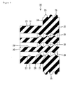
FIG. 4] FIG. 4 is a rear view of the grommet. - Embodiment 1 of the present invention will be described with reference to
FIGS. 1 to 4 .
Agrommet 10 is made of rubber and includes agrommet body 20 having the shape of a substantially cylindrical block. In the case of this embodiment, thegrommet body 20 is configured to be mounted to acasing 60 serving as a mounting body. Thecasing 60 is made of aluminum or an aluminum alloy, and has amounting hole 62 formed so as to pass through aside wall 61 thereof in the axial direction (the front-back direction), into which the entiregrommet body 20 is inserted, as shown inFIG. 1 . As shown inFIG. 2 , astepped section 63 is formed in an axially middle portion of themounting hole 62, which defines the thickness range of theside wall 61, and receivingfaces 64 are formed in a rear portion bounded by thestepped section 63. Thereceiving faces 64 have a flat shape, paired with each other in the height direction, and are arranged substantially parallel to each other. Further,components 66 such as various electronic components are accommodated inside thecasing 60. - The
grommet body 20 has a plurality of electricwire insertion holes 21 formed so as to pass therethrough in the axial direction. As shown inFIGS. 3 and4 , the electricwire insertion holes 21 are arranged in the central portion of thegrommet body 20 so as to be grouped in a slightly horizontally elongated configuration. Also, each of the electricwire insertion holes 21 is configured such that anelectric wire 90 is individually inserted therethrough in the axial direction. - Further, the front end of the
grommet body 20 serves as asealing zone 22, and a portion of thegrommet body 20 that is located rearward of thesealing zone 22 serves as anon-sealing zone 23. Thenon-sealing zone 23 has an axial length longer than the axial length of the sealingzone 22. Aradial step 24 is formed between the outer circumferential face of the sealingzone 22 and the outer circumferential face of thenon-sealing zone 23, and the sealingzone 22 is radially larger than thenon-sealing zone 23, with thestep 24 interposed therebetween. - A plurality of outer
circumferential lips 25 are formed circumferentially around the outer circumferential face of the sealingzone 22. The outercircumferential lips 25 are configured to elastically adhere to the inner circumferential face of the mountinghole 62 around the entire circumference upon mounting to thecasing 60. Also, a plurality of innercircumferential lips 26 are formed circumferentially around the inner circumferential face of the electric wire insertion holes 21 in the sealingzone 22. The innercircumferential lips 26 are configured to elastically adhere to the outer circumferential face of theelectric wires 90 around the entire circumference upon insertion of theelectric wires 90 into the electric wire insertion holes 21. - Note that in a natural state the height dimension of the inner
circumferential lips 26 is smaller than the height dimension of the outercircumferential lips 25, and the width dimension of the innercircumferential lips 26 is larger than the width dimension of the outercircumferential lips 25. Also, some of the innercircumferential lips 26 are disposed inside the electric wire insertion holes 21 in thenon-sealing zone 23. - The inner circumferential face of the electric wire insertion holes 21 in the
non-sealing zone 23 has no innercircumferential lips 26 formed thereon except for the front end thereof, and is formed as a flatcircumferential face 27 without any irregularities. In the case of the present invention, the front end region, in which the innercircumferential lips 26 are formed, of thegrommet body 20 serves as the sealingsection 28, and the rear end region, in which a flatcircumferential face 27 is formed without no innercircumferential lip 26 being formed, serves as anon-sealing section 29. Accordingly, a part of the sealingsection 28 is included in thenon-sealing zone 23. - The inside diameter dimension of the electric wire insertion holes 21 in the
non-sealing section 29 is larger than the inside diameter dimension of the innercircumferential lips 26 of the sealingsection 28. Theelectric wires 90 are inserted in the electric wire insertion holes 21 in thenon-sealing section 29 in a loosely fitted state. Specifically, the inside diameter dimension of the electric wire insertion holes 21 in thenon-sealing section 29 is substantially the same as the inside diameter dimension of the electric wire insertion holes 21 in thesealing section 28 assuming that the electric wire insertion holes 21 do not include the innercircumferential lips 26. In other words, each of the electric wire insertion holes 21 extends continually with substantially the same diameter throughout the entire length of thegrommet body 20 assuming that the innercircumferential lip 26 is not included. - A pair of notched faces 31 are formed in opposed positions, in the height direction, on the outer circumferential face of the
non-sealing zone 23. The two notchedfaces 31 are flat faces along the width direction, and are disposed substantially parallel to each other. Also, a pair of circular-arc faces 32 are formed in opposed positions, in the width direction, on the outer circumferential face of thenon-sealing zone 23 between the two notched faces 31. The two circular-arc faces 32 are disposed concentrically with the outercircumferential lips 25. - Next, the waterproof structure of the
grommet 10 will be described.
Anelectric wire 90 is inserted into each of the electric wire insertion holes 21 of thegrommet body 20. The innercircumferential lips 26 of the sealingsection 28 respectively adhere to the outer circumferential face of theelectric wires 90 in an elastically contracted state, and thereby, the space between each of theelectric wires 90 and thegrommet body 20 is sealed in a liquid-tight manner. Each of theelectric wires 90 is drawn out from both of the front and rear end faces of thegrommet body 20, and both terminals of each of the dawnelectric wires 90 are inserted and held in a connector 70 (seeFIG. 1 ). - The
grommet body 20 is inserted into the mountinghole 62 of thecasing 60 from the front, which is the front face side. When thegrommet body 20 is inserted properly, thestep 24 of thegrommet body 20 is abutted against the steppedsection 63 of the mountinghole 62, and substantially theentire grommet body 20 is accommodated inside the mountinghole 62 in a positioned state (seeFIG. 2 ). At this time, the outercircumferential lips 25 adhere to the inner circumferential face of the mountinghole 62 in an elastically contracted state, and thereby, the space between thegrommet body 20 and thecasing 60 is sealed in a liquid-tight manner. Moreover, the notched faces 31 of thenon-sealing zone 23 of thegrommet body 20 are disposed so as to be capable of coming into contact with the receiving faces 64 of the mountinghole 62 in a surface-to-surface contact state, thereby restricting the free movement of thegrommet body 20 about the axis in the mountinghole 62. Note that theelectric wires 90 drawn out from the rear end face of thegrommet body 20 are bent in a direction substantially orthogonal to the axis in order to avoid interference with thecomponents 66 inside thecasing 60, and thereafter routed along the inner wall face of thecasing 60. At this time, theelectric wires 90 are fixed to the inner wall face of thecasing 60 with aclip 50 provided on the inner wall face of thecasing 60. - A
retainer plate 40 is fixed viabolts 45 to the surface of theside wall 61 so as to surround the mountinghole 62. Theretainer plate 40 is in contact with the portion surrounding the front end face of thegrommet body 20, thereby restricting the withdrawal of thegrommet body 20 toward the front. - As shown in
FIG. 2 , theelectric wires 90 are bent in a direction intersecting with the axis, with the rear end opening edge of each electricwire insertion hole 21 of thegrommet body 20 as a fulcrum. At this time, although theelectric wires 90 are disposed at an angle inside the electric wire insertion holes 21 in thenon-sealing section 29, the angle of inclination is suppressed to a minimum, and the linearity thereof is retained inside the electric wire insertion holes 21 in thesealing section 28. In other words, the formation range of thenon-sealing section 29 is defined as a range in which the linearity of theelectric wires 90 is retained in thesealing section 28. Accordingly, before and after the bending operation of theelectric wires 90, the sealing margin between theelectric wires 90 and the innercircumferential lips 26 will not significantly change, and a predetermined sealing characteristic can be maintained. - As has been described thus far, according to this embodiment, bending the
electric wires 90 drawn out from the rear end face of thegrommet body 20 makes it possible to suppress the swinging of thegrommet body 20 with thenon-sealing section 29 and retain the linearity of theelectric wires 90 in thesealing section 28, and therefore, the sealing characteristic of thegrommet body 20 can be maintained with the sealingsection 28. Consequently, degradation of the sealing characteristic of thegrommet 10 is prevented - Further, the inside diameter dimension of the electric wire insertion holes 21 in the
non-sealing section 29 is substantially the same as the inside diameter dimension of the electric wire insertion holes 21 in thesealing section 28 assuming that the electric wire insertion holes 21 do not include the innercircumferential lips 26, and therefore, thenon-sealing section 29 will not become significantly large. - Since the notched faces 31 of the
non-sealing zone 23 are received by the receiving faces 64 of the mountinghole 62 of thecasing 60 in a surface-to-surface contact state, it is possible to avoid deformation of thenon-sealing zone 23 and hence deformation of thenon-sealing section 29 in the bending direction of theelectric wires 90 when theelectric wires 90 drawn out from the rear end face of thegrommet body 20 are bent. Accordingly, it is possible to reduce the influence of the swinging of theelectric wires 90 that is exerted on thesealing section 28 in a more reliable manner. - Moreover, since the
entire grommet body 20 is accommodated inside the mountinghole 62 of thecasing 60, it is possible to prevent the withdrawal of thegrommet body 20 from the inside of the mountinghole 62 in an effective manner, while securing a large sealing margin between thegrommet body 20 and the mountingbody 60. - The present invention is not limited to the embodiment described by the above statements and drawings, and, for example, the following embodiments also fall within the technical scope of the present invention.
- (1) In Embodiment 1, the grommet is constituted by a grommet body. However, according to the present invention, the grommet may include a portion other than a grommet body.
- (2) In Embodiment 1, the formation range of the non-sealing zone is larger than the formation range of the sealing zone. However, according to the present invention, the formation range of the sealing zone may be larger than the formation range of the non-sealing zone.
- (3) In Embodiment 1, the sealing section is formed on the front end side of the grommet body, and the non-sealing section is formed on the rear end side of the grommet body. However, according to the present invention, the sealing section may be formed on the rear end side of the grommet body, and the non-sealing section may be formed on the front end side of the grommet body. In this case, the sealing section is disposed on the front face side of the casing.
-
- 10
- Grommet
- 20
- Grommet body
- 21
- Electric wire insertion hole
- 25
- Outer circumferential lip
- 26
- Inner circumferential lip
- 28
- Sealing section
- 29
- Non-sealing section
- 31
- Notched face
- 60
- Casing (Mounting body)
- 62
- Mounting hole
- 64
- Receiving face
- 90
- Electric wire
Claims (10)
- A grommet comprising:a grommet body having an electric wire insertion hole through which an electric wire is inserted in the axial direction, the electric wire being drawn out from both end faces in the axial direction, and the grommet body being inserted in a mounting hole of a mounting body;a sealing section disposed on one end of the electric wire insertion hole of the grommet body in the axial direction, and having an inner circumferential lip formed on an inner circumferential face of the electric wire insertion hole, the inner circumferential lip elastically adhering to the electric wire; anda non-sealing section disposed on another end of the electric wire insertion hole of the grommet body in the axial direction and having no inner circumferential lip on the inner circumferential face of the electric wire insertion hole, the electric wire insertion hole in the non-sealing section having an inside diameter dimension larger than an inside diameter dimension of the inner circumferential lip in the sealing section, a formation range of the non-sealing section being defined such that the linearity of the electric wire in the sealing section is retained when the electric wire drawn out from the other end face of the grommet body is bent.
- The grommet according to claim 1,
wherein an outer circumferential lip that elastically adheres to the inner circumferential face of the mounting hole is formed on an outer circumferential face of the sealing section. - The grommet according to claim 1,
wherein the electric wire insertion hole of the non-sealing section has an inside diameter dimension that is substantially the same as an inside diameter dimension of the electric wire insertion hole assuming that the sealing section does not include the inner circumferential lip. - The grommet according to claim 1,
wherein the one end of the grommet body in the axial direction serves as a sealing zone including the sealing section, the other end of the grommet body in the axial direction serves as a non-sealing zone including the non-sealing section, a radial step is formed between the sealing zone and the non-sealing zone, and the sealing zone is radially larger than the non-sealing zone, with the step interposed therebetween. - The grommet according to claim 4, wherein the non-sealing zone has an axial length greater than an axial length of the sealing zone.
- The grommet according to claim 4, wherein a part of the sealing section is included in the non-sealing zone.
- A waterproof structure of a grommet in which the grommet body is inserted in the mounting hole of the mounting body in the grommet according to claim 1,
wherein a pair of flat notched faces are formed in opposed positions on the outer circumferential face of the non-sealing section, and a pair of receiving faces for receiving the notched faces in a surface-to-surface contact state are formed in opposed positions on the inner circumferential face of the mounting hole. - The waterproof structure of a grommet according to claim 7, wherein the entire grommet body is accommodated inside the mounting hole.
- The waterproof structure of a grommet according to claim 7,
wherein the one end of the grommet body in the axial direction serves as a sealing zone including the sealing section, and the other end of the grommet body in the axial direction serves as a non-sealing zone inducing the non-sealing section, a radial step is formed between the sealing zone and the non-sealing zone, and the sealing zone is radially larger than the non-sealing zone, with the step interposed therebetween, and
wherein a stepped section is formed on the inner circumferential face of the mounting hole, the receiving faces are formed on the other end bounded by the stepped section, and the step is abutted against the stepped section when the grommet body is inserted properly into the mounting hole. - The waterproof structure of a grommet according to claim 9,
wherein after insertion of the grommet body into the mounting hole, a retainer plate is fixed via a bolt to the surface of the mounting body, and the retainer plate is in contact with a portion surrounding the one end face of the grommet body.
Applications Claiming Priority (2)
| Application Number | Priority Date | Filing Date | Title |
|---|---|---|---|
| JP2010077771A JP5359961B2 (en) | 2010-03-30 | 2010-03-30 | Grommet and grommet waterproof structure |
| PCT/JP2010/068364 WO2011121829A1 (en) | 2010-03-30 | 2010-10-19 | Grommet and waterproof structure for grommet |
Publications (3)
| Publication Number | Publication Date |
|---|---|
| EP2555362A1 true EP2555362A1 (en) | 2013-02-06 |
| EP2555362A4 EP2555362A4 (en) | 2014-05-21 |
| EP2555362B1 EP2555362B1 (en) | 2016-08-31 |
Family
ID=44711604
Family Applications (1)
| Application Number | Title | Priority Date | Filing Date |
|---|---|---|---|
| EP10849002.0A Not-in-force EP2555362B1 (en) | 2010-03-30 | 2010-10-19 | Grommet and waterproof structure for grommet |
Country Status (3)
| Country | Link |
|---|---|
| EP (1) | EP2555362B1 (en) |
| JP (1) | JP5359961B2 (en) |
| WO (1) | WO2011121829A1 (en) |
Families Citing this family (6)
| Publication number | Priority date | Publication date | Assignee | Title |
|---|---|---|---|---|
| JP6943615B2 (en) * | 2017-05-16 | 2021-10-06 | 矢崎総業株式会社 | Grommets and wire harnesses |
| CA3176241A1 (en) | 2020-05-13 | 2021-11-18 | GAF Energy LLC | Electrical cable passthrough |
| DE102020004934A1 (en) * | 2020-08-13 | 2022-02-17 | Auto-Kabel Management Gmbh | Gasket for an electric cable |
| CN112161114A (en) * | 2020-09-21 | 2021-01-01 | 孝感华工高理电子有限公司 | Cross waterproof plug of line and fixed knot constructs thereof |
| JP7807912B2 (en) * | 2021-12-24 | 2026-01-28 | シャープ株式会社 | Communication equipment and bushings |
| JP7766991B2 (en) * | 2023-10-02 | 2025-11-11 | 矢崎総業株式会社 | Manufacturing method for electric wire with grommet |
Family Cites Families (11)
| Publication number | Priority date | Publication date | Assignee | Title |
|---|---|---|---|---|
| JPS62119147U (en) * | 1985-09-13 | 1987-07-29 | ||
| GB2216736B (en) * | 1988-02-12 | 1992-09-02 | Yazaki Corp | Waterproof plug for electrical connector |
| JPH04315780A (en) * | 1991-04-12 | 1992-11-06 | Fujikura Ltd | Waterproof connector |
| JP2568578Y2 (en) * | 1992-01-31 | 1998-04-15 | 住友電装株式会社 | Rubber parts for waterproof connectors |
| JPH10247546A (en) * | 1993-09-20 | 1998-09-14 | Sumitomo Wiring Syst Ltd | Rubber plug for water-proof connector |
| JP2575409Y2 (en) * | 1993-10-26 | 1998-06-25 | 住友電装株式会社 | Rubber stopper for waterproof connector |
| JP3010411B2 (en) * | 1994-03-18 | 2000-02-21 | 矢崎総業株式会社 | Waterproof rubber stopper and waterproof connector |
| JPH0822862A (en) * | 1994-07-07 | 1996-01-23 | Yazaki Corp | Waterproof rubber stopper |
| JPH08274479A (en) * | 1994-11-17 | 1996-10-18 | Mitsumi Electric Co Ltd | Holding structure for cord bushing |
| JPH11273481A (en) * | 1998-03-19 | 1999-10-08 | Nec Eng Ltd | Cable bushing |
| JP2004120911A (en) * | 2002-09-26 | 2004-04-15 | Mitsubishi Motors Corp | In-wheel motor seal structure |
-
2010
- 2010-03-30 JP JP2010077771A patent/JP5359961B2/en not_active Expired - Fee Related
- 2010-10-19 EP EP10849002.0A patent/EP2555362B1/en not_active Not-in-force
- 2010-10-19 WO PCT/JP2010/068364 patent/WO2011121829A1/en not_active Ceased
Also Published As
| Publication number | Publication date |
|---|---|
| JP2011211843A (en) | 2011-10-20 |
| JP5359961B2 (en) | 2013-12-04 |
| EP2555362A4 (en) | 2014-05-21 |
| EP2555362B1 (en) | 2016-08-31 |
| WO2011121829A1 (en) | 2011-10-06 |
Similar Documents
| Publication | Publication Date | Title |
|---|---|---|
| EP2555362B1 (en) | Grommet and waterproof structure for grommet | |
| US9716377B2 (en) | Electrical wire protection member | |
| JP2009187789A (en) | Waterproof plug and connector | |
| US20160039368A1 (en) | Grommet | |
| US20040266270A1 (en) | Connector for apparatus | |
| EP2882057A1 (en) | Grommet | |
| JP2011250568A (en) | Seal structure for wire outlet hole | |
| EP3184864A1 (en) | Sealing structure | |
| JP2014138519A (en) | Grommet | |
| US20090189357A1 (en) | Shaft seal having integrated removal feature | |
| US11621106B2 (en) | Waterproof connector and device with connector | |
| JP5369805B2 (en) | Waterproof connector | |
| JP6515820B2 (en) | Pipe attachment parts and end structure of pipe | |
| US20230387673A1 (en) | Cable gland | |
| US20060249915A1 (en) | Shaft seal having integrated removal feature | |
| WO2019142762A1 (en) | Connector | |
| US10989686B2 (en) | Gas sensor | |
| JP6152823B2 (en) | Grommet | |
| US20170110826A1 (en) | Sealing member and connector | |
| CN106461080A (en) | Seal structure | |
| JP6070467B2 (en) | Grommet and wire harness with grommet | |
| EP2583355B1 (en) | Emi connector ferrule and assembly combination therewith | |
| CN110611227B (en) | External crimping shielding sleeve and connector using the same | |
| US11456559B2 (en) | Rubber plug wire seal | |
| CN109027038B (en) | clutch release system |
Legal Events
| Date | Code | Title | Description |
|---|---|---|---|
| PUAI | Public reference made under article 153(3) epc to a published international application that has entered the european phase |
Free format text: ORIGINAL CODE: 0009012 |
|
| 17P | Request for examination filed |
Effective date: 20120830 |
|
| AK | Designated contracting states |
Kind code of ref document: A1 Designated state(s): AL AT BE BG CH CY CZ DE DK EE ES FI FR GB GR HR HU IE IS IT LI LT LU LV MC MK MT NL NO PL PT RO RS SE SI SK SM TR |
|
| DAX | Request for extension of the european patent (deleted) | ||
| A4 | Supplementary search report drawn up and despatched |
Effective date: 20140417 |
|
| RIC1 | Information provided on ipc code assigned before grant |
Ipc: H02G 3/22 20060101AFI20140411BHEP Ipc: H02G 15/013 20060101ALI20140411BHEP Ipc: H01R 13/52 20060101ALI20140411BHEP Ipc: B60R 16/02 20060101ALI20140411BHEP Ipc: H01B 17/58 20060101ALI20140411BHEP |
|
| 17Q | First examination report despatched |
Effective date: 20151124 |
|
| GRAP | Despatch of communication of intention to grant a patent |
Free format text: ORIGINAL CODE: EPIDOSNIGR1 |
|
| INTG | Intention to grant announced |
Effective date: 20160412 |
|
| GRAS | Grant fee paid |
Free format text: ORIGINAL CODE: EPIDOSNIGR3 |
|
| GRAA | (expected) grant |
Free format text: ORIGINAL CODE: 0009210 |
|
| AK | Designated contracting states |
Kind code of ref document: B1 Designated state(s): AL AT BE BG CH CY CZ DE DK EE ES FI FR GB GR HR HU IE IS IT LI LT LU LV MC MK MT NL NO PL PT RO RS SE SI SK SM TR |
|
| REG | Reference to a national code |
Ref country code: CH Ref legal event code: EP Ref country code: GB Ref legal event code: FG4D |
|
| REG | Reference to a national code |
Ref country code: IE Ref legal event code: FG4D |
|
| REG | Reference to a national code |
Ref country code: FR Ref legal event code: PLFP Year of fee payment: 7 |
|
| REG | Reference to a national code |
Ref country code: DE Ref legal event code: R096 Ref document number: 602010036119 Country of ref document: DE |
|
| REG | Reference to a national code |
Ref country code: AT Ref legal event code: REF Ref document number: 825718 Country of ref document: AT Kind code of ref document: T Effective date: 20161015 |
|
| REG | Reference to a national code |
Ref country code: LT Ref legal event code: MG4D |
|
| REG | Reference to a national code |
Ref country code: NL Ref legal event code: MP Effective date: 20160831 |
|
| REG | Reference to a national code |
Ref country code: AT Ref legal event code: MK05 Ref document number: 825718 Country of ref document: AT Kind code of ref document: T Effective date: 20160831 |
|
| PG25 | Lapsed in a contracting state [announced via postgrant information from national office to epo] |
Ref country code: FI Free format text: LAPSE BECAUSE OF FAILURE TO SUBMIT A TRANSLATION OF THE DESCRIPTION OR TO PAY THE FEE WITHIN THE PRESCRIBED TIME-LIMIT Effective date: 20160831 Ref country code: RS Free format text: LAPSE BECAUSE OF FAILURE TO SUBMIT A TRANSLATION OF THE DESCRIPTION OR TO PAY THE FEE WITHIN THE PRESCRIBED TIME-LIMIT Effective date: 20160831 Ref country code: HR Free format text: LAPSE BECAUSE OF FAILURE TO SUBMIT A TRANSLATION OF THE DESCRIPTION OR TO PAY THE FEE WITHIN THE PRESCRIBED TIME-LIMIT Effective date: 20160831 Ref country code: LT Free format text: LAPSE BECAUSE OF FAILURE TO SUBMIT A TRANSLATION OF THE DESCRIPTION OR TO PAY THE FEE WITHIN THE PRESCRIBED TIME-LIMIT Effective date: 20160831 Ref country code: NO Free format text: LAPSE BECAUSE OF FAILURE TO SUBMIT A TRANSLATION OF THE DESCRIPTION OR TO PAY THE FEE WITHIN THE PRESCRIBED TIME-LIMIT Effective date: 20161130 |
|
| PG25 | Lapsed in a contracting state [announced via postgrant information from national office to epo] |
Ref country code: AT Free format text: LAPSE BECAUSE OF FAILURE TO SUBMIT A TRANSLATION OF THE DESCRIPTION OR TO PAY THE FEE WITHIN THE PRESCRIBED TIME-LIMIT Effective date: 20160831 Ref country code: SE Free format text: LAPSE BECAUSE OF FAILURE TO SUBMIT A TRANSLATION OF THE DESCRIPTION OR TO PAY THE FEE WITHIN THE PRESCRIBED TIME-LIMIT Effective date: 20160831 Ref country code: BE Free format text: LAPSE BECAUSE OF NON-PAYMENT OF DUE FEES Effective date: 20161031 Ref country code: ES Free format text: LAPSE BECAUSE OF FAILURE TO SUBMIT A TRANSLATION OF THE DESCRIPTION OR TO PAY THE FEE WITHIN THE PRESCRIBED TIME-LIMIT Effective date: 20160831 Ref country code: LV Free format text: LAPSE BECAUSE OF FAILURE TO SUBMIT A TRANSLATION OF THE DESCRIPTION OR TO PAY THE FEE WITHIN THE PRESCRIBED TIME-LIMIT Effective date: 20160831 Ref country code: GR Free format text: LAPSE BECAUSE OF FAILURE TO SUBMIT A TRANSLATION OF THE DESCRIPTION OR TO PAY THE FEE WITHIN THE PRESCRIBED TIME-LIMIT Effective date: 20161201 Ref country code: NL Free format text: LAPSE BECAUSE OF FAILURE TO SUBMIT A TRANSLATION OF THE DESCRIPTION OR TO PAY THE FEE WITHIN THE PRESCRIBED TIME-LIMIT Effective date: 20160831 |
|
| PG25 | Lapsed in a contracting state [announced via postgrant information from national office to epo] |
Ref country code: RO Free format text: LAPSE BECAUSE OF FAILURE TO SUBMIT A TRANSLATION OF THE DESCRIPTION OR TO PAY THE FEE WITHIN THE PRESCRIBED TIME-LIMIT Effective date: 20160831 Ref country code: EE Free format text: LAPSE BECAUSE OF FAILURE TO SUBMIT A TRANSLATION OF THE DESCRIPTION OR TO PAY THE FEE WITHIN THE PRESCRIBED TIME-LIMIT Effective date: 20160831 |
|
| REG | Reference to a national code |
Ref country code: DE Ref legal event code: R119 Ref document number: 602010036119 Country of ref document: DE |
|
| PG25 | Lapsed in a contracting state [announced via postgrant information from national office to epo] |
Ref country code: BG Free format text: LAPSE BECAUSE OF FAILURE TO SUBMIT A TRANSLATION OF THE DESCRIPTION OR TO PAY THE FEE WITHIN THE PRESCRIBED TIME-LIMIT Effective date: 20161130 Ref country code: SM Free format text: LAPSE BECAUSE OF FAILURE TO SUBMIT A TRANSLATION OF THE DESCRIPTION OR TO PAY THE FEE WITHIN THE PRESCRIBED TIME-LIMIT Effective date: 20160831 Ref country code: BE Free format text: LAPSE BECAUSE OF FAILURE TO SUBMIT A TRANSLATION OF THE DESCRIPTION OR TO PAY THE FEE WITHIN THE PRESCRIBED TIME-LIMIT Effective date: 20160831 Ref country code: DK Free format text: LAPSE BECAUSE OF FAILURE TO SUBMIT A TRANSLATION OF THE DESCRIPTION OR TO PAY THE FEE WITHIN THE PRESCRIBED TIME-LIMIT Effective date: 20160831 Ref country code: PT Free format text: LAPSE BECAUSE OF FAILURE TO SUBMIT A TRANSLATION OF THE DESCRIPTION OR TO PAY THE FEE WITHIN THE PRESCRIBED TIME-LIMIT Effective date: 20170102 Ref country code: CZ Free format text: LAPSE BECAUSE OF FAILURE TO SUBMIT A TRANSLATION OF THE DESCRIPTION OR TO PAY THE FEE WITHIN THE PRESCRIBED TIME-LIMIT Effective date: 20160831 Ref country code: PL Free format text: LAPSE BECAUSE OF FAILURE TO SUBMIT A TRANSLATION OF THE DESCRIPTION OR TO PAY THE FEE WITHIN THE PRESCRIBED TIME-LIMIT Effective date: 20160831 Ref country code: SK Free format text: LAPSE BECAUSE OF FAILURE TO SUBMIT A TRANSLATION OF THE DESCRIPTION OR TO PAY THE FEE WITHIN THE PRESCRIBED TIME-LIMIT Effective date: 20160831 |
|
| REG | Reference to a national code |
Ref country code: CH Ref legal event code: PL |
|
| PG25 | Lapsed in a contracting state [announced via postgrant information from national office to epo] |
Ref country code: IT Free format text: LAPSE BECAUSE OF FAILURE TO SUBMIT A TRANSLATION OF THE DESCRIPTION OR TO PAY THE FEE WITHIN THE PRESCRIBED TIME-LIMIT Effective date: 20160831 |
|
| PLBE | No opposition filed within time limit |
Free format text: ORIGINAL CODE: 0009261 |
|
| STAA | Information on the status of an ep patent application or granted ep patent |
Free format text: STATUS: NO OPPOSITION FILED WITHIN TIME LIMIT |
|
| GBPC | Gb: european patent ceased through non-payment of renewal fee |
Effective date: 20161130 |
|
| REG | Reference to a national code |
Ref country code: IE Ref legal event code: MM4A |
|
| PG25 | Lapsed in a contracting state [announced via postgrant information from national office to epo] |
Ref country code: LI Free format text: LAPSE BECAUSE OF NON-PAYMENT OF DUE FEES Effective date: 20161031 Ref country code: DE Free format text: LAPSE BECAUSE OF NON-PAYMENT OF DUE FEES Effective date: 20170503 Ref country code: CH Free format text: LAPSE BECAUSE OF NON-PAYMENT OF DUE FEES Effective date: 20161031 |
|
| 26N | No opposition filed |
Effective date: 20170601 |
|
| PG25 | Lapsed in a contracting state [announced via postgrant information from national office to epo] |
Ref country code: LU Free format text: LAPSE BECAUSE OF NON-PAYMENT OF DUE FEES Effective date: 20161019 Ref country code: SI Free format text: LAPSE BECAUSE OF FAILURE TO SUBMIT A TRANSLATION OF THE DESCRIPTION OR TO PAY THE FEE WITHIN THE PRESCRIBED TIME-LIMIT Effective date: 20160831 |
|
| REG | Reference to a national code |
Ref country code: FR Ref legal event code: PLFP Year of fee payment: 8 |
|
| PG25 | Lapsed in a contracting state [announced via postgrant information from national office to epo] |
Ref country code: GB Free format text: LAPSE BECAUSE OF NON-PAYMENT OF DUE FEES Effective date: 20161130 Ref country code: IE Free format text: LAPSE BECAUSE OF NON-PAYMENT OF DUE FEES Effective date: 20161019 |
|
| PG25 | Lapsed in a contracting state [announced via postgrant information from national office to epo] |
Ref country code: HU Free format text: LAPSE BECAUSE OF FAILURE TO SUBMIT A TRANSLATION OF THE DESCRIPTION OR TO PAY THE FEE WITHIN THE PRESCRIBED TIME-LIMIT; INVALID AB INITIO Effective date: 20101019 Ref country code: CY Free format text: LAPSE BECAUSE OF FAILURE TO SUBMIT A TRANSLATION OF THE DESCRIPTION OR TO PAY THE FEE WITHIN THE PRESCRIBED TIME-LIMIT Effective date: 20160831 |
|
| PG25 | Lapsed in a contracting state [announced via postgrant information from national office to epo] |
Ref country code: IS Free format text: LAPSE BECAUSE OF FAILURE TO SUBMIT A TRANSLATION OF THE DESCRIPTION OR TO PAY THE FEE WITHIN THE PRESCRIBED TIME-LIMIT Effective date: 20160831 Ref country code: MK Free format text: LAPSE BECAUSE OF FAILURE TO SUBMIT A TRANSLATION OF THE DESCRIPTION OR TO PAY THE FEE WITHIN THE PRESCRIBED TIME-LIMIT Effective date: 20160831 Ref country code: MT Free format text: LAPSE BECAUSE OF NON-PAYMENT OF DUE FEES Effective date: 20161031 Ref country code: MC Free format text: LAPSE BECAUSE OF FAILURE TO SUBMIT A TRANSLATION OF THE DESCRIPTION OR TO PAY THE FEE WITHIN THE PRESCRIBED TIME-LIMIT Effective date: 20160831 Ref country code: TR Free format text: LAPSE BECAUSE OF FAILURE TO SUBMIT A TRANSLATION OF THE DESCRIPTION OR TO PAY THE FEE WITHIN THE PRESCRIBED TIME-LIMIT Effective date: 20160831 |
|
| REG | Reference to a national code |
Ref country code: FR Ref legal event code: PLFP Year of fee payment: 9 |
|
| PG25 | Lapsed in a contracting state [announced via postgrant information from national office to epo] |
Ref country code: AL Free format text: LAPSE BECAUSE OF FAILURE TO SUBMIT A TRANSLATION OF THE DESCRIPTION OR TO PAY THE FEE WITHIN THE PRESCRIBED TIME-LIMIT Effective date: 20160831 |
|
| PGFP | Annual fee paid to national office [announced via postgrant information from national office to epo] |
Ref country code: FR Payment date: 20180913 Year of fee payment: 9 |
|
| PG25 | Lapsed in a contracting state [announced via postgrant information from national office to epo] |
Ref country code: FR Free format text: LAPSE BECAUSE OF NON-PAYMENT OF DUE FEES Effective date: 20191031 |