EP2555313A2 - Storage battery device - Google Patents
Storage battery device Download PDFInfo
- Publication number
- EP2555313A2 EP2555313A2 EP20120164156 EP12164156A EP2555313A2 EP 2555313 A2 EP2555313 A2 EP 2555313A2 EP 20120164156 EP20120164156 EP 20120164156 EP 12164156 A EP12164156 A EP 12164156A EP 2555313 A2 EP2555313 A2 EP 2555313A2
- Authority
- EP
- European Patent Office
- Prior art keywords
- storage battery
- alternating current
- output
- battery
- inverter
- Prior art date
- Legal status (The legal status is an assumption and is not a legal conclusion. Google has not performed a legal analysis and makes no representation as to the accuracy of the status listed.)
- Withdrawn
Links
Images


Classifications
-
- H—ELECTRICITY
- H01—ELECTRIC ELEMENTS
- H01M—PROCESSES OR MEANS, e.g. BATTERIES, FOR THE DIRECT CONVERSION OF CHEMICAL ENERGY INTO ELECTRICAL ENERGY
- H01M10/00—Secondary cells; Manufacture thereof
- H01M10/60—Heating or cooling; Temperature control
- H01M10/63—Control systems
- H01M10/637—Control systems characterised by the use of reversible temperature-sensitive devices, e.g. NTC, PTC or bimetal devices; characterised by control of the internal current flowing through the cells, e.g. by switching
-
- H—ELECTRICITY
- H01—ELECTRIC ELEMENTS
- H01M—PROCESSES OR MEANS, e.g. BATTERIES, FOR THE DIRECT CONVERSION OF CHEMICAL ENERGY INTO ELECTRICAL ENERGY
- H01M10/00—Secondary cells; Manufacture thereof
- H01M10/60—Heating or cooling; Temperature control
- H01M10/62—Heating or cooling; Temperature control specially adapted for specific applications
- H01M10/625—Vehicles
-
- H—ELECTRICITY
- H01—ELECTRIC ELEMENTS
- H01M—PROCESSES OR MEANS, e.g. BATTERIES, FOR THE DIRECT CONVERSION OF CHEMICAL ENERGY INTO ELECTRICAL ENERGY
- H01M2220/00—Batteries for particular applications
- H01M2220/20—Batteries in motive systems, e.g. vehicle, ship, plane
-
- Y—GENERAL TAGGING OF NEW TECHNOLOGICAL DEVELOPMENTS; GENERAL TAGGING OF CROSS-SECTIONAL TECHNOLOGIES SPANNING OVER SEVERAL SECTIONS OF THE IPC; TECHNICAL SUBJECTS COVERED BY FORMER USPC CROSS-REFERENCE ART COLLECTIONS [XRACs] AND DIGESTS
- Y02—TECHNOLOGIES OR APPLICATIONS FOR MITIGATION OR ADAPTATION AGAINST CLIMATE CHANGE
- Y02E—REDUCTION OF GREENHOUSE GAS [GHG] EMISSIONS, RELATED TO ENERGY GENERATION, TRANSMISSION OR DISTRIBUTION
- Y02E60/00—Enabling technologies; Technologies with a potential or indirect contribution to GHG emissions mitigation
- Y02E60/10—Energy storage using batteries
Definitions
- Embodiments described herein relate generally to a storage battery device having a warm-up function.
- the car is required to start easily even in a low-temperature atmosphere in which the ambient temperature is approximately -30°C. Therefore, it is required to take some remedies for storage batteries having characteristics in which the output power is reduced in the low-temperature atmosphere.
- a method for warming the storage battery is proposed as a method for compensating for a reduction in the output power of the storage battery in the low-temperature atmosphere.
- the following methods are proposed as the method for warming the storage battery.
- a storage battery device which passes a current without causing charging/discharging on average through a battery by supplying an alternating current to the battery at the low-temperature time, heats the battery from inside to warm the battery and stabilizes the output characteristic of the battery.
- the storage battery device includes a storage battery, an alternating current generation device, and a DC blocking filter.
- the storage battery includes an internal resistor that converts power energy passed therethrough to thermal energy.
- the alternating current generation device includes an alternating current generation device that supplies an alternating current to the storage battery and the DC blocking filter blocks a direct current output to the alternating current generation device from the storage battery.
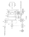
- FIG. 1 is a block diagram showing the simplified configuration of a hybrid car using two driving sources of a motor and engine. An example in which this embodiment is applied to the hybrid car is explained, but this application example does not limit the scope of this invention.
- FIG. 1 a plurality of cells are connected in series as a storage battery 11.
- the storage battery is represented as one battery having the cells provided therein.
- the storage battery 11 is connected to the positive and negative terminals of an inverter 20 via coils L1, L2 that block an alternating current (and/or an AC voltage).
- An AC blocking filter 12 includes coils L1, L2.
- a circuit between the positive and negative terminals of the storage battery 11 and the positive and negative terminals of the inverter 20 may be referred to as a main wiring circuit in some cases.
- the blocking effect of the AC blocking filter 12 becomes more significant as the frequency of an alternating current supplied from an alternating current generation device 10 becomes higher. Therefore, if a low frequency is used, the AC blocking filter 12 may sometimes not be used.
- the positive and negative output terminals of a charger 22 may be connected to the positive and negative terminals of the storage battery 11 via coils L1, L2.
- a plug 23 used for drawing power from the exterior at the time of charging to the storage battery 11 is provided in the charger 22.
- a car having the above function is called a plug-in hybrid car and is a vehicle having a mechanism capable of charging the storage battery 11 from the exterior of the car.
- the AC output terminals of the alternating current generation device 10 are connected to the positive and negative terminals of the storage battery 11 via capacitors C1, C2.
- a DC blocking filter 13 includes capacitors C1, C2.
- a control unit 50 is a control device that controls an inverter, storage battery, engine and the like. It acquires temperature information of a battery from a battery-monitoring unit of the storage battery 11. When the temperature of the storage battery 11 becomes lower than a preset temperature previously set, the control unit 50 turns on the alternating current generation device 10. Then, the alternating current generation device 10 supplies an alternating current to the storage battery 11. Since a DC output of the storage battery 11 is blocked by means of the DC blocking filter 13, a reverse current to the alternating current generation device 10 is prevented. Further, since an alternating current from the alternating current generation device 10 is blocked by means of the AC blocking filter 12, input to the inverter 20 is prevented.
- the battery is heated by an alternating current flowing through the internal resistor of the battery and the temperature of the storage battery 11 rises.
- the AC blocking filter 12 is provided on the inverter 20 side, an alternating current supplied from the alternating current generation device 10 is suppressed from flowing into the input capacitor of the inverter 20 and the storage battery 11 can be efficiently warmed.
- the state of charge (SOC) of the battery is kept unchanged. Further, if the frequency range used is adequately selected, a large alternating current can be supplied while suppressing deterioration of the storage battery 11 and the storage battery 11 can rapidly and efficiently be warmed. As the frequency range, a frequency near the resonance frequency of the storage battery 11 may be selected, for example.
- control unit 50 interrupts output of the alternating current generation device 10 and interrupts supply of an alternating current to the storage battery 11.
- the inverter 20 converts a DC voltage from the storage battery 11 to a three-phase alternating current and supplies the same to a motor 31.
- the rotation power of the motor 31 is transmitted to a wheel 33 via a decelerator 32. At this time, that is, when the decelerated rotation power of the motor 31 is transmitted to the wheel 33, the rotation power is added to the rotation power of an engine 41 using oil or natural gas as an energy source and then transmitted to the wheel 33.
- the rotation of a shaft of the engine 41 is transmitted to a generator (that may be called an alternator) 42.
- a three-phase alternating current generated from the generator 42 is rectified by means of a rectifier 43 and then charged to an auxiliary battery 44 (for example, 12 V).
- the auxiliary battery 44 is used as a power source of onboard electrical equipment such as operating power sources for onboard lights, car navigator, ignition of an engine, cooling device and the like, a power source of the control unit 50 and the like.
- motion energy of the car obtained from the wheel 33 can be regenerated to the storage battery 11 by using the motor 31 as a generator based on the control of the control unit 50. Further, the storage battery 11 may be charged by means of the engine 41 by driving the motor 31 as a generator.
- the motor 31 is used not only as the electric motor but also as the generator, but the electric motor and generator can be separately mounted.
- the alternating current generation device 10 can variously be formed in embodiments and is explained below.
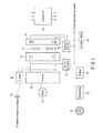
- FIG. 2 shows another embodiment.
- the same portions as those of FIG. 1 are denoted by the same symbols as those of FIG. 1 and the repetitive explanation is omitted.
- the AC output terminals of a multiphase/two-phase converter 46 (for example, a Scott transformer) are connected to the positive and negative terminals of a storage battery 11 via capacitors C1, C2.
- Capacitors C1, C2 configure a DC blocking filter 13.
- a three-phase alternating current generated form a generator 42 is further coupled to the multiphase/two-phase converter 46 via a switch 45.
- the switch 45 is on/off-controlled by means of a control unit 50.
- the control unit 50 receives temperature information of a battery from a battery-monitoring unit of the storage battery 11. When the temperature of the storage battery 11 becomes lower than a preset temperature, the control unit 50 turns on the switch 45. Then, the multiphase/two-phase converter 46 converts a three-phase output of the generator 42 to a two-phase alternating current and supplies the same to the storage battery 11. Since the DC output of the storage battery 11 is blocked by means of the DC blocking filter 13, a reverse current will not be supplied to the multiphase/two-phase converter 46. Further, since the alternating current from the multiphase/two-phase converter 46 is blocked by means of an AC blocking filter 12, the current will not be input to the inverter 20.
- the battery is heated by an alternating current flowing through the internal resistor of the battery and the storage battery 11 is warmed.
- the control unit 50 opens the switch 45 to interrupt supply of the alternating current to the storage battery 11.
- the rotation speed of the engine 41 can be controlled to be set in a target frequency range based on the control unit 50 while the alternating current is being supplied to the storage battery 11. Further, a fuel supply amount to the engine 41 can be adjusted based on the control of the control unit 50 to compensate for a load variation of the engine 41 caused by a load variation of the generator 42 that varies according to the on/off state of the switch 45.
- the generator 42 is directly coupled with the output shaft of the engine 41, but may be connected thereto via a decelerator or another power transmission means.
- the generators supply the same power, the loss of one of the generators tends to become smaller as an output voltage thereof becomes higher. Therefore, it is preferable to adjust the turn ratio of the transformer and set a high-voltage small current on the primary side (generator 42 side) and a low-voltage large current on the secondary side (storage battery side) at the multiphase/two-phase conversion time instead of acquiring a low-voltage large current required for warming the storage battery 11 directly from the generator 42. If the generator 42 is of a two-phase output type, the multiphase/two-phase conversion becomes unnecessary.
- the storage battery 11 includes 100 cells, for example, and the output voltage thereof is selected in a range of 200 to 400 V, for example.
- the present system may be designed to make it possible to select the power (current and voltage) of a high-frequency alternating current used for warming the battery based on the scale of the storage battery 11 and various conditions.
- the difference (A2-A1) between present temperature A1 of the battery and target high temperature A2 and time T required for reaching temperature A2 may be previously actually measured and measurement data may be stored in a memory as a table. Then, the present system may be designed to make it possible to freely select a combination of a current of 1, 5 and 10 A and a voltage of 1, 10 and 20 V, for example, as an alternating current as required time T becomes shorter. Since the temperature-rise characteristics at the warming time are different according to the protection cover and arrangement state of the storage battery 11 and the output standard of the storage battery 11, a plurality of tables of the measurement data may be formed for the respective storage batteries.
- Adjustment means capable of adjusting the period and time in which the warming operation for the storage battery 11 is performed according to the use environment of a car (for example, a case wherein an emergency start is required as in an ambulance or a case of parking for a long time) may be provided between the control unit and operating unit.
- FIG. 3 shows still another embodiment.
- the above embodiment shows a case wherein the generator 42 is provided on the engine 41 and an AC output of the generator 42 is converted to a high-frequency alternating current to be supplied to the storage battery 11.
- FIG. 3 shows one example of a storage battery device that can be applied to a car of this type.
- the same portions as those of FIG. 2 are denoted by the same symbols as those of FIG. 2 and the repetitive explanation thereof is omitted.
- the positive and negative input terminals of a DC-DC converter 47 are connected to the positive and negative terminals of a storage battery 11 via an AC blocking filter 12.
- An output voltage of 12 V, for example, converted by the DC-DC converter 47 is supplied to an auxiliary battery 44.
- the output terminal of the auxiliary battery 44 is connected to the input terminal of a warming inverter 48.
- the output terminal of the warming inverter 48 is connected to the storage battery 11 via a DC blocking filter 13.
- the warming inverter 48 is an inverter controlled by a control unit 50. When determining that the storage battery 11 is to be warmed, the control unit 50 drives the warming inverter 48. The warming inverter 48 performs DC-AC conversion to output an alternating current and supplies the alternating current to the storage battery 11. As a result, the storage battery 11 is heated and warmed.
- the warming inverter 48 includes a semiconductor switch element (field-effect transistor [FET], insulated-gate bipolar transistor [TGBT] or the like) for a switching operation.
- FET field-effect transistor
- TGBT insulated-gate bipolar transistor
- power of the auxiliary battery 44 is converted to an alternating current by means of the warming inverter 48.
- this embodiment is not limited to this case and power can be directly obtained from the storage battery 11.
- the storage battery 11 can be warmed while suppressing the power consumption of the auxiliary battery 44.
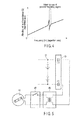
- the storage battery uses metal such as aluminum for the electrodes and the AC impedance between the positive and negative electrodes exhibits an inductive impedance characteristic in a relatively high frequency (approximately 100 kHz or more). For this reason, a resonance point as shown in FIG. 4 exists in the AC impedance between the positive and negative electrodes of the storage battery.
- the abscissa represents a frequency and the ordinate represents the absolute value of AC impedance.
- a current that does not cause charging/discharging is passed through the battery to heat the battery from the internal portion and warm the battery and the output characteristic at the low-temperature time can be improved by supplying an alternating current to the battery at the low-temperature time.
- FIG. 5 shows the principle of the internal configuration of the generator 42, switch 45 and multiphase/two-phase converter 46 shown in FIG. 2 .
- a rotor of the generator 42 having a permanent magnet When a rotor of the generator 42 having a permanent magnet is rotated and driven by the engine 41, an induction current flows through a stator having a coil and is output as an alternating current (in this example, a two-phase alternating current).
- the alternating current is supplied to a multiphase/two-phase converter 46 (in this example, two-phase/two-phase converter) via the switch 45.
- the turn ratio of the converter 46 is adequately adjusted to set a high-voltage small current on the primary side (generator 42 side) and a low-voltage large current on the secondary side (storage battery side).
- the switch 45 is turned on and an output current of the converter 46 is supplied to the storage battery 11 via the DC blocking filter 13.
- FIG. 6 shows the principle of the internal configuration of the warming inverter 48 shown in FIG. 3 .
- the input electrode of a switching transistor 48a is connected to the positive electrode of the auxiliary battery 44 and the output electrode of the switching transistor 48a is connected to an earth line via the primary winding of a transformer 48b.
- the secondary winding of the transformer 48b is connected to the storage battery 11 via the DC blocking filter 13.
- An on/off control signal of the switching transistor 48a is obtained from the control unit 50.
- FIG. 7 shows an example in which current amount adjusters 61a, 61b are provided in a passage through which an alternating current for warming is supplied to the storage battery 11.
- the current amount adjusters 61a, 61b are controlled by the control unit 50.
- the current amount may be varied according to a variation in the battery temperature. That is, when supply of an alternating current is started, the battery temperature starts to rise, but at this time, since the reaction is slow if the battery temperature is low, a large current amount is set in the initial stage and the current amount is reduced after the battery temperature reaches a preset temperature.
- the current amount can be varied with time by subjecting an on/off control signal of the switching transistor 48a to pulse width modulation and supplying the thus obtained signal.
- the above embodiment can be applied to not only the driving sources of the electric car, hybrid car but also the driving source of an electric vehicle using a storage battery as a driving power source, for example, a forklift or two-wheeled vehicle. Further, the embodiment is not limited to the electric vehicle but can be applied to an outdoor storage battery, power supply plant or the like.
Landscapes
- Engineering & Computer Science (AREA)
- Automation & Control Theory (AREA)
- Manufacturing & Machinery (AREA)
- Chemical & Material Sciences (AREA)
- Chemical Kinetics & Catalysis (AREA)
- Electrochemistry (AREA)
- General Chemical & Material Sciences (AREA)
- Secondary Cells (AREA)
- Electric Propulsion And Braking For Vehicles (AREA)
- Charge And Discharge Circuits For Batteries Or The Like (AREA)
- Hybrid Electric Vehicles (AREA)
Abstract
Description
- Embodiments described herein relate generally to a storage battery device having a warm-up function.
- Recently, much attention is paid to cars such as electric cars or hybrid cars mainly having storage batteries as power drive sources. A phenomenon that the series equivalent resistance significantly increases in a low-temperature atmosphere below freezing point is observed in most of chemical batteries such as lithium ion batteries or nickel-hydrogen batteries. These batteries are widely used as storage batteries mounted on the electric cars and the output power thereof is extremely reduced in comparison with the normal temperature time.
- The car is required to start easily even in a low-temperature atmosphere in which the ambient temperature is approximately -30°C. Therefore, it is required to take some remedies for storage batteries having characteristics in which the output power is reduced in the low-temperature atmosphere.
- A method for warming the storage battery is proposed as a method for compensating for a reduction in the output power of the storage battery in the low-temperature atmosphere. For example, the following methods are proposed as the method for warming the storage battery.
- (1) The use prediction time of an electric vehicle having a storage battery mounted thereon is managed by use of a timer. Then, the storage battery is charged and warmed before the electric vehicle is used. (2) The temperature of the storage battery is detected and the storage battery is discharged and warmed when the temperature thereof is reduced. (3) A to-be-warmed part is a capacitor and it is warmed from the exterior by means of a heater.
- With a method for warming the battery from the exterior by means of a heater, it takes a long time until the battery is warmed depending on the efficiency of heat conduction to the battery and the rate of a temperature rise. On the other hand, with the conventional method for warming the battery from inside, a sufficiently large charging/discharging current that increases the temperature cannot be passed therethrough from the viewpoint of protection depending on the state of charge (fully charged or almost completely discharged) of the battery. Further, there occurs a problem that the battery life is reduced if the battery is rapidly charged or discharged with such a large current as to warm the battery.
-
-
FIG. 1 is a diagram showing a typical example of the configuration of one embodiment. -
FIG. 2 is a diagram showing a typical example of the configuration of another embodiment. -
FIG. 3 is a diagram showing a typical example of the configuration of still another embodiment. -
FIG. 4 is a frequency characteristic diagram showing a resonance point appearing when an alternating current is supplied to a storage battery. -
FIG. 5 is a diagram showing the principle of the internal configuration of agenerator 42,switch 45 and multiphase/two-phase converter 46 shown inFIG. 2 . -
FIG. 6 is a diagram showing the principle of the internal configuration of awarming inverter 48 shown inFIG. 3 . -
FIG. 7 is a diagram showing an example in which a current amount adjuster is provided in a passage via which an alternating current for warming is supplied to the storage battery. - In general, according to one embodiment, there is provided a storage battery device which passes a current without causing charging/discharging on average through a battery by supplying an alternating current to the battery at the low-temperature time, heats the battery from inside to warm the battery and stabilizes the output characteristic of the battery.
- According to an embodiment of the present disclosure, the storage battery device includes a storage battery, an alternating current generation device, and a DC blocking filter. The storage battery includes an internal resistor that converts power energy passed therethrough to thermal energy. The alternating current generation device includes an alternating current generation device that supplies an alternating current to the storage battery and the DC blocking filter blocks a direct current output to the alternating current generation device from the storage battery.
- An embodiment will further be described with reference to the drawings.
-
FIG. 1 is a block diagram showing the simplified configuration of a hybrid car using two driving sources of a motor and engine. An example in which this embodiment is applied to the hybrid car is explained, but this application example does not limit the scope of this invention. - In
FIG. 1 , a plurality of cells are connected in series as astorage battery 11. In this embodiment, the storage battery is represented as one battery having the cells provided therein. - The
storage battery 11 is connected to the positive and negative terminals of aninverter 20 via coils L1, L2 that block an alternating current (and/or an AC voltage). - An
AC blocking filter 12 includes coils L1, L2. A circuit between the positive and negative terminals of thestorage battery 11 and the positive and negative terminals of theinverter 20 may be referred to as a main wiring circuit in some cases. The blocking effect of theAC blocking filter 12 becomes more significant as the frequency of an alternating current supplied from an alternatingcurrent generation device 10 becomes higher. Therefore, if a low frequency is used, theAC blocking filter 12 may sometimes not be used. - The positive and negative output terminals of a
charger 22 may be connected to the positive and negative terminals of thestorage battery 11 via coils L1, L2. Aplug 23 used for drawing power from the exterior at the time of charging to thestorage battery 11 is provided in thecharger 22. A car having the above function is called a plug-in hybrid car and is a vehicle having a mechanism capable of charging thestorage battery 11 from the exterior of the car. - Further, the AC output terminals of the alternating
current generation device 10 are connected to the positive and negative terminals of thestorage battery 11 via capacitors C1, C2. - A
DC blocking filter 13 includes capacitors C1, C2. - A
control unit 50 is a control device that controls an inverter, storage battery, engine and the like. It acquires temperature information of a battery from a battery-monitoring unit of thestorage battery 11. When the temperature of thestorage battery 11 becomes lower than a preset temperature previously set, thecontrol unit 50 turns on the alternatingcurrent generation device 10. Then, the alternatingcurrent generation device 10 supplies an alternating current to thestorage battery 11. Since a DC output of thestorage battery 11 is blocked by means of theDC blocking filter 13, a reverse current to the alternatingcurrent generation device 10 is prevented. Further, since an alternating current from the alternatingcurrent generation device 10 is blocked by means of theAC blocking filter 12, input to theinverter 20 is prevented. - As a result, the battery is heated by an alternating current flowing through the internal resistor of the battery and the temperature of the
storage battery 11 rises. - Since the
AC blocking filter 12 is provided on theinverter 20 side, an alternating current supplied from the alternatingcurrent generation device 10 is suppressed from flowing into the input capacitor of theinverter 20 and thestorage battery 11 can be efficiently warmed. - Since charging/discharging is not performed on average by supplying an alternating current to the
storage battery 11, the state of charge (SOC) of the battery is kept unchanged. Further, if the frequency range used is adequately selected, a large alternating current can be supplied while suppressing deterioration of thestorage battery 11 and thestorage battery 11 can rapidly and efficiently be warmed. As the frequency range, a frequency near the resonance frequency of thestorage battery 11 may be selected, for example. - When the warming process is completed, the
control unit 50 interrupts output of the alternatingcurrent generation device 10 and interrupts supply of an alternating current to thestorage battery 11. - The
inverter 20 converts a DC voltage from thestorage battery 11 to a three-phase alternating current and supplies the same to amotor 31. The rotation power of themotor 31 is transmitted to awheel 33 via adecelerator 32. At this time, that is, when the decelerated rotation power of themotor 31 is transmitted to thewheel 33, the rotation power is added to the rotation power of anengine 41 using oil or natural gas as an energy source and then transmitted to thewheel 33. - The rotation of a shaft of the
engine 41 is transmitted to a generator (that may be called an alternator) 42. A three-phase alternating current generated from thegenerator 42 is rectified by means of arectifier 43 and then charged to an auxiliary battery 44 (for example, 12 V). Theauxiliary battery 44 is used as a power source of onboard electrical equipment such as operating power sources for onboard lights, car navigator, ignition of an engine, cooling device and the like, a power source of thecontrol unit 50 and the like. - In the above car, motion energy of the car obtained from the
wheel 33 can be regenerated to thestorage battery 11 by using themotor 31 as a generator based on the control of thecontrol unit 50. Further, thestorage battery 11 may be charged by means of theengine 41 by driving themotor 31 as a generator. Themotor 31 is used not only as the electric motor but also as the generator, but the electric motor and generator can be separately mounted. - The alternating
current generation device 10 can variously be formed in embodiments and is explained below. -
FIG. 2 shows another embodiment. InFIG. 2 , the same portions as those ofFIG. 1 are denoted by the same symbols as those ofFIG. 1 and the repetitive explanation is omitted. In the case of the embodiment ofFIG. 2 , the AC output terminals of a multiphase/two-phase converter 46 (for example, a Scott transformer) are connected to the positive and negative terminals of astorage battery 11 via capacitors C1, C2. Capacitors C1, C2 configure aDC blocking filter 13. - A three-phase alternating current generated form a
generator 42 is further coupled to the multiphase/two-phase converter 46 via aswitch 45. Theswitch 45 is on/off-controlled by means of acontrol unit 50. Thecontrol unit 50 receives temperature information of a battery from a battery-monitoring unit of thestorage battery 11. When the temperature of thestorage battery 11 becomes lower than a preset temperature, thecontrol unit 50 turns on theswitch 45. Then, the multiphase/two-phase converter 46 converts a three-phase output of thegenerator 42 to a two-phase alternating current and supplies the same to thestorage battery 11. Since the DC output of thestorage battery 11 is blocked by means of theDC blocking filter 13, a reverse current will not be supplied to the multiphase/two-phase converter 46. Further, since the alternating current from the multiphase/two-phase converter 46 is blocked by means of anAC blocking filter 12, the current will not be input to theinverter 20. - As a result, the battery is heated by an alternating current flowing through the internal resistor of the battery and the
storage battery 11 is warmed. When the warming process is completed, thecontrol unit 50 opens theswitch 45 to interrupt supply of the alternating current to thestorage battery 11. - The rotation speed of the
engine 41 can be controlled to be set in a target frequency range based on thecontrol unit 50 while the alternating current is being supplied to thestorage battery 11. Further, a fuel supply amount to theengine 41 can be adjusted based on the control of thecontrol unit 50 to compensate for a load variation of theengine 41 caused by a load variation of thegenerator 42 that varies according to the on/off state of theswitch 45. - In
FIG. 2 , thegenerator 42 is directly coupled with the output shaft of theengine 41, but may be connected thereto via a decelerator or another power transmission means. Generally, if the generators supply the same power, the loss of one of the generators tends to become smaller as an output voltage thereof becomes higher. Therefore, it is preferable to adjust the turn ratio of the transformer and set a high-voltage small current on the primary side (generator 42 side) and a low-voltage large current on the secondary side (storage battery side) at the multiphase/two-phase conversion time instead of acquiring a low-voltage large current required for warming thestorage battery 11 directly from thegenerator 42. If thegenerator 42 is of a two-phase output type, the multiphase/two-phase conversion becomes unnecessary. - Although not necessarily limited to this case, the
storage battery 11 includes 100 cells, for example, and the output voltage thereof is selected in a range of 200 to 400 V, for example. Further, the present system may be designed to make it possible to select the power (current and voltage) of a high-frequency alternating current used for warming the battery based on the scale of thestorage battery 11 and various conditions. - For example, the difference (A2-A1) between present temperature A1 of the battery and target high temperature A2 and time T required for reaching temperature A2 may be previously actually measured and measurement data may be stored in a memory as a table. Then, the present system may be designed to make it possible to freely select a combination of a current of 1, 5 and 10 A and a voltage of 1, 10 and 20 V, for example, as an alternating current as required time T becomes shorter. Since the temperature-rise characteristics at the warming time are different according to the protection cover and arrangement state of the
storage battery 11 and the output standard of thestorage battery 11, a plurality of tables of the measurement data may be formed for the respective storage batteries. - Adjustment means capable of adjusting the period and time in which the warming operation for the
storage battery 11 is performed according to the use environment of a car (for example, a case wherein an emergency start is required as in an ambulance or a case of parking for a long time) may be provided between the control unit and operating unit. -
FIG. 3 shows still another embodiment. The above embodiment shows a case wherein thegenerator 42 is provided on theengine 41 and an AC output of thegenerator 42 is converted to a high-frequency alternating current to be supplied to thestorage battery 11. - However, in some hybrid cars, a generator is not provided on the
engine 41. Further, an electric car in which theengine 41 is not mounted and only themotor 31 is used as a driving source is present.FIG. 3 shows one example of a storage battery device that can be applied to a car of this type. InFIG. 3 , the same portions as those ofFIG. 2 are denoted by the same symbols as those ofFIG. 2 and the repetitive explanation thereof is omitted. As shown inFIG. 3 , the positive and negative input terminals of a DC-DC converter 47 are connected to the positive and negative terminals of astorage battery 11 via anAC blocking filter 12. An output voltage of 12 V, for example, converted by the DC-DC converter 47 is supplied to anauxiliary battery 44. - The output terminal of the
auxiliary battery 44 is connected to the input terminal of a warminginverter 48. The output terminal of the warminginverter 48 is connected to thestorage battery 11 via aDC blocking filter 13. - The warming
inverter 48 is an inverter controlled by acontrol unit 50. When determining that thestorage battery 11 is to be warmed, thecontrol unit 50 drives the warminginverter 48. The warminginverter 48 performs DC-AC conversion to output an alternating current and supplies the alternating current to thestorage battery 11. As a result, thestorage battery 11 is heated and warmed. The warminginverter 48 includes a semiconductor switch element (field-effect transistor [FET], insulated-gate bipolar transistor [TGBT] or the like) for a switching operation. - In the above embodiment, power of the
auxiliary battery 44 is converted to an alternating current by means of the warminginverter 48. However, this embodiment is not limited to this case and power can be directly obtained from thestorage battery 11. - In this case, it is suitable to draw power that is voltage-reduced by means of a transformer from between the
AC blocking filter 12 and aninverter 20. The transformer may be included in the warminginverter 48. With this configuration, energy obtained from thestorage battery 11 as a drive current of the warminginverter 48 is supplied to thestorage battery 11 as an alternating current. Therefore, in comparison with the former embodiment, thestorage battery 11 can be warmed while suppressing the power consumption of theauxiliary battery 44. - Further, power used to generate an alternating current is obtained from the
storage battery 11. Therefore, energy consumption in the internal resistor of the storage battery generated by drawing a current from thestorage battery 11 is added to energy consumption in the internal resistor of the storage battery generated by supplying an alternating current. As a result, in this embodiment, it becomes possible to acquire approximately two times a heating value attained in a case wherein power is obtained from a portion other than the storage battery and an alternating current of the same amplitude is supplied. - Next, the frequency of an alternating current supplied for warming the
storage battery 11 is explained. The storage battery uses metal such as aluminum for the electrodes and the AC impedance between the positive and negative electrodes exhibits an inductive impedance characteristic in a relatively high frequency (approximately 100 kHz or more). For this reason, a resonance point as shown inFIG. 4 exists in the AC impedance between the positive and negative electrodes of the storage battery. In the characteristic diagram ofFIG. 4 , the abscissa represents a frequency and the ordinate represents the absolute value of AC impedance. When an alternating current is supplied to the storage battery having the above resonance point and if the frequency of the alternating current is selected to a frequency near the resonance point, a large current with a low voltage can be passed through thestorage battery 11 and it becomes advantageous in manufacturing the warming inverter. - As described above, a current that does not cause charging/discharging is passed through the battery to heat the battery from the internal portion and warm the battery and the output characteristic at the low-temperature time can be improved by supplying an alternating current to the battery at the low-temperature time.
-
FIG. 5 shows the principle of the internal configuration of thegenerator 42,switch 45 and multiphase/two-phase converter 46 shown inFIG. 2 . When a rotor of thegenerator 42 having a permanent magnet is rotated and driven by theengine 41, an induction current flows through a stator having a coil and is output as an alternating current (in this example, a two-phase alternating current). The alternating current is supplied to a multiphase/two-phase converter 46 (in this example, two-phase/two-phase converter) via theswitch 45. In this case, the turn ratio of theconverter 46 is adequately adjusted to set a high-voltage small current on the primary side (generator 42 side) and a low-voltage large current on the secondary side (storage battery side). At the warming time, theswitch 45 is turned on and an output current of theconverter 46 is supplied to thestorage battery 11 via theDC blocking filter 13. -
FIG. 6 shows the principle of the internal configuration of the warminginverter 48 shown inFIG. 3 . The input electrode of a switchingtransistor 48a is connected to the positive electrode of theauxiliary battery 44 and the output electrode of the switchingtransistor 48a is connected to an earth line via the primary winding of atransformer 48b. The secondary winding of thetransformer 48b is connected to thestorage battery 11 via theDC blocking filter 13. An on/off control signal of the switchingtransistor 48a is obtained from thecontrol unit 50. -
FIG. 7 shows an example in whichcurrent amount adjusters storage battery 11. Thecurrent amount adjusters control unit 50. For example, after supply of an alternating current to thestorage battery 11 is started, the current amount may be varied according to a variation in the battery temperature. That is, when supply of an alternating current is started, the battery temperature starts to rise, but at this time, since the reaction is slow if the battery temperature is low, a large current amount is set in the initial stage and the current amount is reduced after the battery temperature reaches a preset temperature. In the case of the circuit configuration ofFIG. 6 , the current amount can be varied with time by subjecting an on/off control signal of the switchingtransistor 48a to pulse width modulation and supplying the thus obtained signal. - The above embodiment can be applied to not only the driving sources of the electric car, hybrid car but also the driving source of an electric vehicle using a storage battery as a driving power source, for example, a forklift or two-wheeled vehicle. Further, the embodiment is not limited to the electric vehicle but can be applied to an outdoor storage battery, power supply plant or the like.
- The embodiments of this invention are explained above, but these embodiments are presented as an example, and they are not intended to limit the scope of this invention. The novel embodiments can be embodied in other various forms and various omissions, substitutions and changes can be made without departing from the spirit of this invention. For example, the number of cells configuring the storage battery,11 may be set to one or a plurality of cells may be connected in series or in parallel. The embodiments and modifications are included in the scope and spirit of the invention and are included in the scope of the inventions described in claims and the range equivalent thereto.
- While certain embodiments have been described, these embodiments have been presented by way of example only, and are not intended to limit the scope of the inventions. Indeed, the novel embodiments described herein may be embodied in a variety of other forms; furthermore, various omissions, substitutions and changes in the form of the embodiments described herein may be made without departing from the spirit of the inventions. The accompanying claims and their equivalents are intended to cover such forms or modifications as would fall within the scope and spirit of the inventions.
Claims (8)
- A storage battery device characterized by comprising:a storage battery (11) configured to include an internal resistor that converts power energy passed therethrough to thermal energy,an alternating current generation device (10) configured to supply an alternating current to the storage battery, anda DC blocking filter (13) configured to block a direct current output to the alternating current generation device from the storage battery.
- The storage battery device according to claim 1, characterized by further comprising:an inverter (20) configured to convert a direct current output from the storage battery (11) to an alternating current, andan AC blocking filter (12) configured to block an alternating current output from the alternating current generation device (10) to the inverter (20) via the storage battery (11).
- The storage battery device according to claim 1, characterized in that the alternating current generation device is a converter (46) that converts an output from a generator driven (42) by an engine to the alternating current.
- The storage battery device according to claim 1, characterized in that the alternating current generation device is a second inverter (48) that converts a direct current from an auxiliary battery (44) to the alternating current.
- The storage battery device according to claim 4, characterized in that the second inverter (48) converts an output voltage from a DC-DC converter (47) that converts a DC output generated in the AC blocking filter to the alternating current.
- The battery device according to claim 4, characterized in that the second inverter (48) converts an output of the AC blocking filter (12) directly to the alternating current.
- The storage battery device according to claim 1, characterized by further comprising:a current amount adjuster (61a, 61b) configured to adjust a current amount between the DC blocking filter and the alternating current generation device.
- The storage battery device according to any one of claims 1 to 7, characterized in that an output of the inverter is supplied as power to a motor (31).
Applications Claiming Priority (1)
| Application Number | Priority Date | Filing Date | Title |
|---|---|---|---|
| JP2011172385A JP2013037859A (en) | 2011-08-05 | 2011-08-05 | Storage battery device |
Publications (2)
| Publication Number | Publication Date |
|---|---|
| EP2555313A2 true EP2555313A2 (en) | 2013-02-06 |
| EP2555313A3 EP2555313A3 (en) | 2014-02-19 |
Family
ID=45976776
Family Applications (1)
| Application Number | Title | Priority Date | Filing Date |
|---|---|---|---|
| EP20120164156 Withdrawn EP2555313A3 (en) | 2011-08-05 | 2012-04-13 | Storage battery device |
Country Status (4)
| Country | Link |
|---|---|
| US (1) | US20130033232A1 (en) |
| EP (1) | EP2555313A3 (en) |
| JP (1) | JP2013037859A (en) |
| CN (1) | CN102916233B (en) |
Families Citing this family (22)
| Publication number | Priority date | Publication date | Assignee | Title |
|---|---|---|---|---|
| US9821810B2 (en) * | 2012-09-14 | 2017-11-21 | Ford Global Technologies, Llc | Method and system for heating auxiliary battery of vehicle |
| JP6179190B2 (en) * | 2013-05-23 | 2017-08-16 | 日本電気株式会社 | Power supply system and battery preheating method |
| US9536065B2 (en) | 2013-08-23 | 2017-01-03 | Morphotrust Usa, Llc | System and method for identity management |
| US20150258946A1 (en) * | 2014-03-13 | 2015-09-17 | GM Global Technology Operations LLC | Split-rail vehicle power architecture |
| CN103887578B (en) * | 2014-03-25 | 2016-03-30 | 东风汽车公司 | Improve electrokinetic cell heating means and the system of electric automobile low temperature course continuation mileage |
| JP6367027B2 (en) * | 2014-07-09 | 2018-08-01 | 住友建機株式会社 | Construction machinery |
| EP3168629B1 (en) * | 2014-07-11 | 2018-06-20 | Nissan Motor Co., Ltd | Apparatus for measuring an impedance of fuel cell and method of measuring an impedance of fuel cell |
| JP6388285B2 (en) * | 2015-03-03 | 2018-09-12 | 日立建機株式会社 | Hybrid construction machine |
| JPWO2018025344A1 (en) * | 2016-08-03 | 2018-09-20 | 三菱電機株式会社 | Electric vacuum cleaner |
| JP6972084B2 (en) * | 2016-08-03 | 2021-11-24 | 三菱電機株式会社 | Vacuum cleaner |
| WO2019230157A1 (en) * | 2018-05-30 | 2019-12-05 | 住友電気工業株式会社 | Temperature raising device for secondary battery, computer program, and method for raising temperature of secondary battery |
| JP6808687B2 (en) * | 2018-07-04 | 2021-01-06 | 住友建機株式会社 | Construction machinery |
| JP7204367B2 (en) * | 2018-08-02 | 2023-01-16 | 本田技研工業株式会社 | Vehicle power control device |
| CN111261978B (en) * | 2020-01-16 | 2021-11-23 | 武汉理工大学 | Energy storage power station winter heat preservation method based on energy storage battery alternating current preheating |
| JP7837862B2 (en) * | 2020-05-18 | 2026-03-31 | 阿波製紙株式会社 | Insulation sheet |
| JP7519831B2 (en) | 2020-07-17 | 2024-07-22 | 本田技研工業株式会社 | Heating device |
| US20220102769A1 (en) * | 2020-09-30 | 2022-03-31 | GM Global Technology Operations LLC | Architecture for battery self heating |
| JP7580322B2 (en) * | 2021-03-30 | 2024-11-11 | 本田技研工業株式会社 | Heating device, heating program, and heating method |
| JP7218468B1 (en) * | 2022-08-15 | 2023-02-06 | 正一 田中 | Alternating current supply circuit for batteries |
| JP7301208B1 (en) | 2022-12-05 | 2023-06-30 | 正一 田中 | Alternating current supply circuit for batteries |
| DE102023108118B3 (en) | 2023-03-30 | 2024-05-29 | Rainer Marquardt | Device and method for heating traction batteries |
| CN117353430B (en) * | 2023-12-04 | 2024-02-23 | 南京中电科能技术有限公司 | Energy storage operation control method based on energy storage temperature rise characteristic constraint |
Family Cites Families (10)
| Publication number | Priority date | Publication date | Assignee | Title |
|---|---|---|---|---|
| US2710937A (en) * | 1952-11-03 | 1955-06-14 | Fox Prod Co | Method and apparatus for heating batteries |
| US4222000A (en) * | 1977-07-15 | 1980-09-09 | Lucas Industries Limited | Battery heating system |
| US5362942A (en) * | 1993-08-24 | 1994-11-08 | Interdigital Technology Corporation | Battery heating system using internal battery resistance |
| JPH09259937A (en) * | 1996-03-22 | 1997-10-03 | Mitsubishi Chem Corp | Preheating method and preheating device for secondary battery |
| JP4081855B2 (en) * | 1998-05-14 | 2008-04-30 | 日産自動車株式会社 | Battery temperature riser |
| JP4835383B2 (en) * | 2006-10-25 | 2011-12-14 | トヨタ自動車株式会社 | Control device and control method for power supply unit, program for causing computer to realize the method, and recording medium recording the program |
| JP2010285110A (en) * | 2009-06-12 | 2010-12-24 | Toyota Motor Corp | Vehicle and control method thereof |
| JP5293820B2 (en) * | 2009-07-08 | 2013-09-18 | トヨタ自動車株式会社 | Secondary battery temperature increasing device and vehicle equipped with the same |
| KR101230353B1 (en) * | 2010-01-28 | 2013-02-06 | 주식회사 엘지화학 | Battery Pack System of Improving Low Temperature Performance Using Internal Resistance of Cell |
| JP5502603B2 (en) * | 2010-06-04 | 2014-05-28 | 本田技研工業株式会社 | Vehicle battery heating device |
-
2011
- 2011-08-05 JP JP2011172385A patent/JP2013037859A/en active Pending
-
2012
- 2012-04-13 EP EP20120164156 patent/EP2555313A3/en not_active Withdrawn
- 2012-05-07 CN CN201210139013.8A patent/CN102916233B/en not_active Expired - Fee Related
- 2012-06-15 US US13/524,366 patent/US20130033232A1/en not_active Abandoned
Non-Patent Citations (1)
| Title |
|---|
| None |
Also Published As
| Publication number | Publication date |
|---|---|
| CN102916233A (en) | 2013-02-06 |
| CN102916233B (en) | 2015-09-02 |
| JP2013037859A (en) | 2013-02-21 |
| EP2555313A3 (en) | 2014-02-19 |
| US20130033232A1 (en) | 2013-02-07 |
Similar Documents
| Publication | Publication Date | Title |
|---|---|---|
| EP2555313A2 (en) | Storage battery device | |
| JP6228586B2 (en) | Electric vehicle | |
| US8148949B2 (en) | Use of high frequency transformer to charge HEV batteries | |
| US8963482B2 (en) | Power supply apparatus for electrically powered vehicle and method for controlling the same | |
| CN107791855B (en) | Method and apparatus for controlling an on-board charger | |
| US9120390B2 (en) | Apparatus for transferring energy using onboard power electronics and method of manufacturing same | |
| CN101622767B (en) | Generator motor driving device and method for discharging capacitor of generator motor driving device | |
| US9878624B2 (en) | Apparatus for converting power of electric vehicle | |
| US10875418B2 (en) | Charge control apparatus and system | |
| US7012822B2 (en) | Integrated traction inverter module and DC/DC converter | |
| CN106240384B (en) | Energy supply system for motor vehicles | |
| KR20190010786A (en) | Electric vehicle | |
| CN103490460A (en) | System for transferring energy from an energy source and method of making same | |
| US20250201960A1 (en) | Battery heating device and vehicle | |
| EP3782841B1 (en) | System of increasing temperature of battery for vehicle | |
| US20150084413A1 (en) | Method and system for supplying electric power to a hybrid motor vehicle with dual electrical energy storage devices | |
| JP2011229305A (en) | Vehicular charger | |
| JP2013027236A (en) | Battery charging system and vehicle charging system | |
| KR101507863B1 (en) | Driving apparatus for electric vehicle | |
| CN121079221A (en) | Charging device and charging method for an electrical energy store | |
| JP4329454B2 (en) | Electric vehicle system | |
| KR102430074B1 (en) | Obc integrated battery cooling system and method for driving cooling fan thereof | |
| JP2016119167A (en) | Power source system | |
| US20250026216A1 (en) | On-board charging system for an electric vehicle | |
| WO2024173188A1 (en) | Dc fast-charging bidirectional converter utilizing an existing e-motor and inverter |
Legal Events
| Date | Code | Title | Description |
|---|---|---|---|
| PUAI | Public reference made under article 153(3) epc to a published international application that has entered the european phase |
Free format text: ORIGINAL CODE: 0009012 |
|
| 17P | Request for examination filed |
Effective date: 20120413 |
|
| AK | Designated contracting states |
Kind code of ref document: A2 Designated state(s): AL AT BE BG CH CY CZ DE DK EE ES FI FR GB GR HR HU IE IS IT LI LT LU LV MC MK MT NL NO PL PT RO RS SE SI SK SM TR |
|
| AX | Request for extension of the european patent |
Extension state: BA ME |
|
| PUAL | Search report despatched |
Free format text: ORIGINAL CODE: 0009013 |
|
| AK | Designated contracting states |
Kind code of ref document: A3 Designated state(s): AL AT BE BG CH CY CZ DE DK EE ES FI FR GB GR HR HU IE IS IT LI LT LU LV MC MK MT NL NO PL PT RO RS SE SI SK SM TR |
|
| AX | Request for extension of the european patent |
Extension state: BA ME |
|
| RIC1 | Information provided on ipc code assigned before grant |
Ipc: H01M 10/50 20060101AFI20140113BHEP |
|
| RIN1 | Information on inventor provided before grant (corrected) |
Inventor name: KURODA, KAZUTO Inventor name: KOSUGI, SHINICHIRO |
|
| STAA | Information on the status of an ep patent application or granted ep patent |
Free format text: STATUS: THE APPLICATION HAS BEEN WITHDRAWN |
|
| 18W | Application withdrawn |
Effective date: 20150915 |