EP2555083A1 - Mouse charging system - Google Patents
Mouse charging system Download PDFInfo
- Publication number
- EP2555083A1 EP2555083A1 EP11176099A EP11176099A EP2555083A1 EP 2555083 A1 EP2555083 A1 EP 2555083A1 EP 11176099 A EP11176099 A EP 11176099A EP 11176099 A EP11176099 A EP 11176099A EP 2555083 A1 EP2555083 A1 EP 2555083A1
- Authority
- EP
- European Patent Office
- Prior art keywords
- mouse
- conductive piece
- charging
- electronic device
- charging system
- Prior art date
- Legal status (The legal status is an assumption and is not a legal conclusion. Google has not performed a legal analysis and makes no representation as to the accuracy of the status listed.)
- Withdrawn
Links
Images


Classifications
-
- G—PHYSICS
- G06—COMPUTING OR CALCULATING; COUNTING
- G06F—ELECTRIC DIGITAL DATA PROCESSING
- G06F3/00—Input arrangements for transferring data to be processed into a form capable of being handled by the computer; Output arrangements for transferring data from processing unit to output unit, e.g. interface arrangements
- G06F3/01—Input arrangements or combined input and output arrangements for interaction between user and computer
- G06F3/03—Arrangements for converting the position or the displacement of a member into a coded form
- G06F3/033—Pointing devices displaced or positioned by the user, e.g. mice, trackballs, pens or joysticks; Accessories therefor
- G06F3/0354—Pointing devices displaced or positioned by the user, e.g. mice, trackballs, pens or joysticks; Accessories therefor with detection of two-dimensional [2D] relative movements between the device, or an operating part thereof, and a plane or surface, e.g. 2D mice, trackballs, pens or pucks
- G06F3/03543—Mice or pucks
-
- G—PHYSICS
- G06—COMPUTING OR CALCULATING; COUNTING
- G06F—ELECTRIC DIGITAL DATA PROCESSING
- G06F1/00—Details not covered by groups G06F3/00 - G06F13/00 and G06F21/00
- G06F1/26—Power supply means, e.g. regulation thereof
- G06F1/266—Arrangements to supply power to external peripherals either directly from the computer or under computer control, e.g. supply of power through the communication port, computer controlled power-strips
-
- H—ELECTRICITY
- H02—GENERATION; CONVERSION OR DISTRIBUTION OF ELECTRIC POWER
- H02H—EMERGENCY PROTECTIVE CIRCUIT ARRANGEMENTS
- H02H9/00—Emergency protective circuit arrangements for limiting excess current or voltage without disconnection
- H02H9/04—Emergency protective circuit arrangements for limiting excess current or voltage without disconnection responsive to excess voltage
- H02H9/045—Emergency protective circuit arrangements for limiting excess current or voltage without disconnection responsive to excess voltage adapted to a particular application and not provided for elsewhere
- H02H9/046—Emergency protective circuit arrangements for limiting excess current or voltage without disconnection responsive to excess voltage adapted to a particular application and not provided for elsewhere responsive to excess voltage appearing at terminals of integrated circuits
-
- H—ELECTRICITY
- H03—ELECTRONIC CIRCUITRY
- H03K—PULSE TECHNIQUE
- H03K19/00—Logic circuits, i.e. having at least two inputs acting on one output; Inverting circuits
- H03K19/007—Fail-safe circuits
- H03K19/0075—Fail-safe circuits by using two redundant chains
-
- H—ELECTRICITY
- H02—GENERATION; CONVERSION OR DISTRIBUTION OF ELECTRIC POWER
- H02H—EMERGENCY PROTECTIVE CIRCUIT ARRANGEMENTS
- H02H3/00—Emergency protective circuit arrangements for automatic disconnection directly responsive to an undesired change from normal electric working condition with or without subsequent reconnection ; integrated protection
- H02H3/02—Details
- H02H3/05—Details with means for increasing reliability, e.g. redundancy arrangements
Definitions
- the present invention relates to a charging system and more particularly relates to a charging system, where the charge of a wireless mouse is by means of electrically coupling of conductive pieces.
- the ways to energize the wireless mouse comprise: displacing a new battery to the wireless mouse, connecting electrically the wireless mouse with an electronic device by universal serial bus (USB), or plugging the wireless mouse into a charger, and the above various charging ways enable the wireless mouse to keep in use.
- USB universal serial bus
- the way of charging the wireless mouse by a charger improves the problems of replacing the battery and solves the technical problems of power in the wireless mouse and the problems of the environmental protection; however, the charger of any shape or size will always occupy space. Furthermore, the charger needs wires for electrically connecting, and the production brings about cost of material. Moreover, repeated use will also destroy the charger.
- the way of electrical connection of the wireless mouse with an electronic device by USB is similar to that of a wired mouse.
- the only difference is that the wireless mouse is a real cordless type once the USB line is removed after the wireless mouse is fully charged.
- a user shall prepare the wires or the charger by himself (or herself) when the charging is by wires or the charger. Sometimes the user tends to forget to take along the wires or the charger, which would fail to charge the wireless mouse so that the wireless mouse is incapable of being used.
- the present invention provides a mouse charging system for solving multiple problems, comprising environment, economic benefit and use space, relating to the frequent replacement of battery for the traditional wireless mouse or the required carrying of the connecting wires and chargers.
- the present invention discloses a mouse charging system, applying to an electronic device which comprises a power supply and a first connecting port.
- the mouse charging system comprises a mouse and a receiver.
- the mouse comprises a shell, a charging module which is disposed in the shell, and a first conductive piece which is disposed on the shell, and the first conductive piece is electrically connected to the charging module.
- the receiver comprises a second connecting port and a second conductive piece.
- the second connecting port is disposed on one end of the receiver, and the second connecting port is electrically plugging in the first connecting port of the electronic device, resulting in the electrical connection between the second connecting port and the power supply of the electronic device.
- the second conductive piece is disposed on another end of the receiver, and the second conductive piece is selectively coupled to the first conductive piece of the mouse. As the second conductive piece of the receiver and the first conductive piece of the mouse are coupled together, the electrical energy provided by the power supply of the electronic device can be transferred to charge the charging module of the mouse by means of the conduction between the first conductive piece of the mouse and second conductive piece of the receiver.
- the effectiveness of the present invention lies in how the power supply of the electronic device charges the charging module of the mouse of the wireless mouse.
- the second connecting port of the receiver is plugging in the first connecting port of the electronic device during the situation that the wireless mouse is in low voltage or no power state at all and the first conductive piece of the wireless mouse is attached directly to form electrical coupling with the second conductive piece of the receiver.
- FIGS. 1 to 3 show the three-dimensional diagrams and the circuit block diagram.
- the mouse charging system of an embodiment of the present invention a mouse charging system is applying to an electronic device 310.
- the electronic device 310 comprises a power supply 3101 and a first connecting port 3102.
- the mouse charging system comprises a mouse 110 and a receiver 210.
- the mouse 110 and the receiver 210 transmit displacement control signal by wireless communication. That means the mouse 110 receives and transfers signals by the wireless connection through the receiver 210 to operate the cursor of the electronic device 310 for controlling the displacement of cursor to operate the electronic device 310. Controlling the displacement of the cursor in a windows of operation system of the electronic device by a wireless connection is a known technology, thus the applicant does not describe this known technology here.
- the mouse 110 comprises a shell 1101, a first conductive piece 1102, a warning lamp 1103 and a charging module 1104.
- the charging module 1104 is disposed in the mouse 110, and the first conductive piece 1102 is disposed on the shell 1101.
- the first conductive piece 1102 is electrically connected to the charging module 1104.
- the charging module 1104 of the present invention comprises a processing unit 11041, a charging circuit 11042 and a rechargeable battery 11043.
- the processing unit 11041 is electrically connected to the first conductive piece 1102 and the warning lamp 1103 of the mouse 110.
- the charging circuit 11042 is electrically connected to the processing unit 11041.
- the rechargeable battery 11043 is electrically connected to the charging circuit 11042.
- the first conductive piece 1102 of the mouse 110 is powered by the power supply 3101 of the electronic device 310, and the power supply 3101 charges the rechargeable battery 11043 by routing through the processing unit 11041 and the charging circuit 11042.
- the receiver 210 of the present invention comprises a second conductive piece 2101 and a second connecting port 2102.
- the electronic device 310 comprises a power supply 3101 and a first connecting port 3102.
- the receiver 210 selectively takes the second connecting port 2102 to plug in the first connecting port 3102 of the electronic device 310, to connect electrically the receiver 210 and the power supply 3101 of the electronic device 310.
- another function of the receiver 210 is to receive the displacement path of the wireless mouse.
- this is a known technology which won't be described in this embodiment.
- FIG. 3 it shows an exploded view of the mouse charging system of the embodiment of the present invention.
- the first conductive piece 1102 and the second conductive piece 2101 of the embodiment disclosed in the present invention are magnetic conductive pieces.
- the first conductive piece 1102 and the second conductive pieces 2101 are coupled together by magnetic attraction.
- the first conductive piece 1102 and the second conductive piece 2101 are made of iron, nickel, cobalt, ferrosilicon or any material that is used as a magnetic conductor.
- the first conductive piece 1102 and the second conductive piece 2101 take circle, square, rectangle or any other shapes. It's worth to notice that the present invention does not limit the materials and shapes of the first conductive piece 1102 and the second conductive piece 2101.
- For a person skilled in the art could amend the materials and shapes of the first conductive piece 1102 and the second conductive piece 2101 depending on the practical designing requirements or using requirements.
- FIGS. 3 to 5 show the exploded view and diagrams of the charging state.
- the processing unit 11041 of the mouse charging system detects the power state of the rechargeable battery 11043 and selectively signals the warning lamp 1103. Therefore, the warning lamp 1103 signals a warming for showing the user that the wireless mouse needs to charge.
- the warning lamp 1103 of the mouse 110 signals a warming about low voltage or no power state
- the user can take the second connecting port 2102 of the receiver 210 plugging to the first connecting port 3102 of the electronic device 310 at first.
- the receiver 210 is electrically connected to the power supply of the electronic device 310.
- the first conductive piece 1102 of the mouse 110 and the second conductive piece 2101 of the receiver 210 are coupled together by magnetic attraction.
- the electrical energy of the power supply 3101 of the electronic device 310 is from the first connecting port 3102 passing through the second connecting port 2102 and the second conductive piece 2101 of the receiver 210 into the first conductive piece 1102 of the mouse 110, then charges the rechargeable battery 11043 through the charging circuit 11042 and the processing unit 11041 in the charging module 1104 of the mouse 110.
- the warning lamp 1103 of the mouse 110 will signal a warning about the fully charging state for the user. The user can separate the mouse 110 from the receiver 210 and continues to use the wireless mouse.
- FIG. 5 shows a plan view of charging state of the mouse 110 of the present embodiment.
- FIG. 5 illustrates clearly that when the warning lamp 1103 signals a warning about low voltage or no power state, the receiver 210 is plugged into the electronic device 310 and the mouse 110 is electrically connected to the receiver 210 for charging.
- the warning lamp 1103 is triggered to radiate a light color, such as a red flasher, for signaling low voltage or no power state, and radiate another light color, such as a green continuing light, for signaling power fully charging state.
- the present invention does not limit the numbers or light colors of the warning lamps 100. A person skilled in the art could amend the numbers and color lights of the warning lamp 1103 depending on the practical designing requirements or using requirements.
- FIG. 6 it shows a plan view of charging state of the mouse 110 of another embodiment of the present invention.
- any warning lamp 1103 doesn't need to being disposed on the mouse 110.
- a user needs to plug the receiver 210 into the electronic device 310 before he (or she) use the wireless mouse. He (or she) finds the displacements of the cursor in the windows slowly or non-response when he (or she) moves the wireless mouse, and this situation means that the mouse 110 of the wireless mouse in low voltage or no power state. Therefore, the user should keep the mouse 110 connect electrically to the receiver 210 for charging the mouse 110 through the receiver 210.
- the mouse charging system technology disclosed in the present invention can make users without taking along any wires or chargers to charge their wireless mouse.
Landscapes
- Engineering & Computer Science (AREA)
- General Engineering & Computer Science (AREA)
- Theoretical Computer Science (AREA)
- Physics & Mathematics (AREA)
- Computer Hardware Design (AREA)
- General Physics & Mathematics (AREA)
- Microelectronics & Electronic Packaging (AREA)
- Computing Systems (AREA)
- Mathematical Physics (AREA)
- Human Computer Interaction (AREA)
- Charge And Discharge Circuits For Batteries Or The Like (AREA)
- Secondary Cells (AREA)
Abstract
A mouse charging device is applying to an electronic device which comprises a power supply and a first connecting port. The mouse charging device comprises a mouse and a receiver. A charging module of the mouse is disposed in a shell of the mouse, and a first conductive piece of the mouse is disposed on the shell. The first conductive piece is electrically connected to the charging module. The receiver comprises a second connecting port and a second conductive piece. The second connecting port is electrically plugged in the first connecting port and electrically connected to the power supply. The second conductive piece is selectively coupled to the first conductive piece of the mouse. As the second conductive piece and the first conductive piece are coupled together, the power supply of the electronic device is available to charge the charging module of the mouse.
Description
- The present invention relates to a charging system and more particularly relates to a charging system, where the charge of a wireless mouse is by means of electrically coupling of conductive pieces.
- At present, the majority of wireless mice on the market won't work under the conditions of low voltage or no power at all. And the ways to energize the wireless mouse comprise: displacing a new battery to the wireless mouse, connecting electrically the wireless mouse with an electronic device by universal serial bus (USB), or plugging the wireless mouse into a charger, and the above various charging ways enable the wireless mouse to keep in use.
- Although the forgoing ways of replacing a new battery to the wireless mouse and plugging the wireless mouse to a charger for charging the wireless mouse can keep the wireless mouse to continuously operate, however, in a long time use, the wireless mouse still suffers situations as low voltage and even no power. A description is given for the problem of replacing batteries: the battery, which can not be reused for long, will cause environmental and mercury pollution problems to the earth.
- Although the way of charging the wireless mouse by a charger improves the problems of replacing the battery and solves the technical problems of power in the wireless mouse and the problems of the environmental protection; however, the charger of any shape or size will always occupy space. Furthermore, the charger needs wires for electrically connecting, and the production brings about cost of material. Moreover, repeated use will also destroy the charger.
- The way of electrical connection of the wireless mouse with an electronic device by USB is similar to that of a wired mouse. The only difference is that the wireless mouse is a real cordless type once the USB line is removed after the wireless mouse is fully charged.
- However, a user shall prepare the wires or the charger by himself (or herself) when the charging is by wires or the charger. Sometimes the user tends to forget to take along the wires or the charger, which would fail to charge the wireless mouse so that the wireless mouse is incapable of being used.
- In view of the forgoing problems, the present invention provides a mouse charging system for solving multiple problems, comprising environment, economic benefit and use space, relating to the frequent replacement of battery for the traditional wireless mouse or the required carrying of the connecting wires and chargers.
- The present invention discloses a mouse charging system, applying to an electronic device which comprises a power supply and a first connecting port. The mouse charging system comprises a mouse and a receiver. The mouse comprises a shell, a charging module which is disposed in the shell, and a first conductive piece which is disposed on the shell, and the first conductive piece is electrically connected to the charging module.
- The receiver comprises a second connecting port and a second conductive piece. The second connecting port is disposed on one end of the receiver, and the second connecting port is electrically plugging in the first connecting port of the electronic device, resulting in the electrical connection between the second connecting port and the power supply of the electronic device. The second conductive piece is disposed on another end of the receiver, and the second conductive piece is selectively coupled to the first conductive piece of the mouse. As the second conductive piece of the receiver and the first conductive piece of the mouse are coupled together, the electrical energy provided by the power supply of the electronic device can be transferred to charge the charging module of the mouse by means of the conduction between the first conductive piece of the mouse and second conductive piece of the receiver.
- The effectiveness of the present invention lies in how the power supply of the electronic device charges the charging module of the mouse of the wireless mouse. As the second connecting port of the receiver is plugging in the first connecting port of the electronic device during the situation that the wireless mouse is in low voltage or no power state at all and the first conductive piece of the wireless mouse is attached directly to form electrical coupling with the second conductive piece of the receiver. Thus by means of the technique of the present invention, users are available to charge the wireless mouse without taking along any wires or chargers.
- The characteristics, realization and functions of the present invention and disclosed in the following description with reference to the preferred exemplified embodiments and the accompanying drawings.
-
-
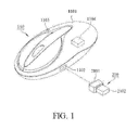
FIG. 1 is a three-dimensional diagram of a mouse charging system of one embodiment of the present invention; -
FIG. 2 is a circuit block diagram of a mouse charging system of one embodiment of the present invention; -
FIG. 3 is an exploded view of a mouse charging system of one embodiment of the present invention; -
FIG. 4 is a three-dimensional schematic diagram of a charging status of the mouse of one embodiment of the present invention; -
FIG. 5 is a plan view of a charging status of the mouse of one embodiment of the present invention; and -
FIG. 6 is a plan view of a charging status of the mouse of another embodiment of the present invention. - Referring to
FIGS. 1 to 3 , they show the three-dimensional diagrams and the circuit block diagram. The mouse charging system of an embodiment of the present invention, a mouse charging system is applying to anelectronic device 310. Theelectronic device 310 comprises apower supply 3101 and a first connectingport 3102. The mouse charging system comprises amouse 110 and areceiver 210. - In this embodiment, the
mouse 110 and thereceiver 210 transmit displacement control signal by wireless communication. That means themouse 110 receives and transfers signals by the wireless connection through thereceiver 210 to operate the cursor of theelectronic device 310 for controlling the displacement of cursor to operate theelectronic device 310. Controlling the displacement of the cursor in a windows of operation system of the electronic device by a wireless connection is a known technology, thus the applicant does not describe this known technology here. - Referring to
FIGS. 1 and2 , themouse 110 comprises ashell 1101, a firstconductive piece 1102, awarning lamp 1103 and acharging module 1104. Thecharging module 1104 is disposed in themouse 110, and the firstconductive piece 1102 is disposed on theshell 1101. The firstconductive piece 1102 is electrically connected to thecharging module 1104. - The
charging module 1104 of the present invention comprises aprocessing unit 11041, acharging circuit 11042 and arechargeable battery 11043. Theprocessing unit 11041 is electrically connected to the firstconductive piece 1102 and thewarning lamp 1103 of themouse 110. Thecharging circuit 11042 is electrically connected to theprocessing unit 11041. Therechargeable battery 11043 is electrically connected to thecharging circuit 11042. Furthermore, the firstconductive piece 1102 of themouse 110 is powered by thepower supply 3101 of theelectronic device 310, and thepower supply 3101 charges therechargeable battery 11043 by routing through theprocessing unit 11041 and thecharging circuit 11042. - Referring again to
FIGS. 1 and2 , thereceiver 210 of the present invention comprises a secondconductive piece 2101 and a second connectingport 2102. Theelectronic device 310 comprises apower supply 3101 and a first connectingport 3102. Thereceiver 210 selectively takes the second connectingport 2102 to plug in the first connectingport 3102 of theelectronic device 310, to connect electrically thereceiver 210 and thepower supply 3101 of theelectronic device 310. In addition, another function of thereceiver 210 is to receive the displacement path of the wireless mouse. However, this is a known technology which won't be described in this embodiment. - Please refer to
FIG. 3 , it shows an exploded view of the mouse charging system of the embodiment of the present invention. The firstconductive piece 1102 and the secondconductive piece 2101 of the embodiment disclosed in the present invention are magnetic conductive pieces. The firstconductive piece 1102 and the secondconductive pieces 2101 are coupled together by magnetic attraction. In this embodiment, the firstconductive piece 1102 and the secondconductive piece 2101 are made of iron, nickel, cobalt, ferrosilicon or any material that is used as a magnetic conductor. Moreover, the firstconductive piece 1102 and the secondconductive piece 2101 take circle, square, rectangle or any other shapes. It's worth to notice that the present invention does not limit the materials and shapes of the firstconductive piece 1102 and the secondconductive piece 2101. For a person skilled in the art could amend the materials and shapes of the firstconductive piece 1102 and the secondconductive piece 2101 depending on the practical designing requirements or using requirements. - Please refer to
FIGS. 3 to 5 , which show the exploded view and diagrams of the charging state. In one embodiment of the present invention, when a user uses the wireless mouse in a long time making the wireless mouse lose power, theprocessing unit 11041 of the mouse charging system detects the power state of therechargeable battery 11043 and selectively signals thewarning lamp 1103. Therefore, thewarning lamp 1103 signals a warming for showing the user that the wireless mouse needs to charge. - For example, please refer to
FIGS. 3 and4 , and go withFIG. 2 at the same time, as thewarning lamp 1103 of themouse 110 signals a warming about low voltage or no power state, the user can take the second connectingport 2102 of thereceiver 210 plugging to the first connectingport 3102 of theelectronic device 310 at first. Thus, thereceiver 210 is electrically connected to the power supply of theelectronic device 310. Subsequently, the firstconductive piece 1102 of themouse 110 and the secondconductive piece 2101 of thereceiver 210 are coupled together by magnetic attraction. At this time, the electrical energy of thepower supply 3101 of theelectronic device 310 is from the first connectingport 3102 passing through the second connectingport 2102 and the secondconductive piece 2101 of thereceiver 210 into the firstconductive piece 1102 of themouse 110, then charges therechargeable battery 11043 through the chargingcircuit 11042 and theprocessing unit 11041 in thecharging module 1104 of themouse 110. When the power reaches the fully charging state, thewarning lamp 1103 of themouse 110 will signal a warning about the fully charging state for the user. The user can separate themouse 110 from thereceiver 210 and continues to use the wireless mouse. - Please refer to
FIG. 5 , it shows a plan view of charging state of themouse 110 of the present embodiment.FIG. 5 illustrates clearly that when thewarning lamp 1103 signals a warning about low voltage or no power state, thereceiver 210 is plugged into theelectronic device 310 and themouse 110 is electrically connected to thereceiver 210 for charging. It's worth to notices that, in this embodiment, thewarning lamp 1103 is triggered to radiate a light color, such as a red flasher, for signaling low voltage or no power state, and radiate another light color, such as a green continuing light, for signaling power fully charging state. However, the present invention does not limit the numbers or light colors of the warning lamps 100. A person skilled in the art could amend the numbers and color lights of thewarning lamp 1103 depending on the practical designing requirements or using requirements. - Please refer to
FIG. 6 , it shows a plan view of charging state of themouse 110 of another embodiment of the present invention. In this embodiment, anywarning lamp 1103 doesn't need to being disposed on themouse 110. In general, a user needs to plug thereceiver 210 into theelectronic device 310 before he (or she) use the wireless mouse. He (or she) finds the displacements of the cursor in the windows slowly or non-response when he (or she) moves the wireless mouse, and this situation means that themouse 110 of the wireless mouse in low voltage or no power state. Therefore, the user should keep themouse 110 connect electrically to thereceiver 210 for charging themouse 110 through thereceiver 210. - As mentioned-above, the mouse charging system technology disclosed in the present invention can make users without taking along any wires or chargers to charge their wireless mouse.
- The present invention has been described with reference to the preferred embodiment thereof and it is understood that the embodiments are not intended to limit the scope of the present invention. Moreover, as the contents disclosed herein should be readily understood and can be implemented by a person skilled in the art, all equivalent changes or modifications which do not depart from the spirit of the present invention should be encompassed by the appended claims.
Claims (7)
- A mouse charging system, applying to an electronic device, the electronic device comprising a power supply and a first connecting port, the mouse charging system comprising:a mouse, comprising:a shell;a charging module, disposed in the shell; anda first conductive piece, disposed on the shell, and the first conductive piece electrically connected to the charging module; anda receiver, comprising:a second connecting port, disposed on one end of said receiver, and the second connecting port electrically plugging in the first connecting port and electrically being connected to the power supply; anda second conductive piece, disposed on another end of said receiver, and the second conductive piece selectively being coupled to the first conductive piece;wherein, as the second conductive piece and the first conductive piece are coupled together, the power supply of the electronic device charges the charging module of said mouse through said receiver.
- A mouse charging system as in claim 1, wherein the charging module further comprises:a processing unit, electrically connected to the first conductive piece;a charging circuit, electrically connected to the processing unit; anda rechargeable battery, electrically connected to the charging circuit;wherein said mouse is powered by the power supply of the electronic device, and the power supply charges the rechargeable battery by routing through the processing unit and the charging circuit.
- A mouse charging system as in claim 2, further comprising a warming lamp electrically connected to the processing unit, and the processing unit selectively signals the warning lamp to trigger said warming lamp to signal a warming.
- A mouse charging system as in claim 1, wherein the first conductive piece and the second conductive piece are magnetic conductive pieces, and the first conductive piece and the second conductive piece are coupled together by magnetic attraction.
- A mouse charging system as in claim 4, wherein the first conductive piece and the second conductive piece are made of iron, nickel, cobalt, ferrosilicon or any material that is used as a magnetic conductor.
- A mouse charging system as in claim 1, wherein the first conductive piece and the second conductive piece take circle, square, rectangle or any other shapes.
- A mouse charging system as in claim 1, wherein said mouse communicates with the electronic device by a wireless connection.
Priority Applications (4)
| Application Number | Priority Date | Filing Date | Title |
|---|---|---|---|
| TW100120066A TW201250523A (en) | 2011-08-01 | 2011-06-09 | Charging system |
| CN2011101673575A CN102841688A (en) | 2011-08-01 | 2011-06-21 | Mouse charging system |
| EP11176099A EP2555083A1 (en) | 2011-08-01 | 2011-08-01 | Mouse charging system |
| JP2011174895A JP2013038987A (en) | 2011-08-01 | 2011-08-10 | Mouse charging system |
Applications Claiming Priority (1)
| Application Number | Priority Date | Filing Date | Title |
|---|---|---|---|
| EP11176099A EP2555083A1 (en) | 2011-08-01 | 2011-08-01 | Mouse charging system |
Publications (1)
| Publication Number | Publication Date |
|---|---|
| EP2555083A1 true EP2555083A1 (en) | 2013-02-06 |
Family
ID=50180724
Family Applications (1)
| Application Number | Title | Priority Date | Filing Date |
|---|---|---|---|
| EP11176099A Withdrawn EP2555083A1 (en) | 2011-08-01 | 2011-08-01 | Mouse charging system |
Country Status (4)
| Country | Link |
|---|---|
| EP (1) | EP2555083A1 (en) |
| JP (1) | JP2013038987A (en) |
| CN (1) | CN102841688A (en) |
| TW (1) | TW201250523A (en) |
Families Citing this family (1)
| Publication number | Priority date | Publication date | Assignee | Title |
|---|---|---|---|---|
| CN108845684A (en) * | 2018-05-31 | 2018-11-20 | 苏州树云网络科技有限公司 | A kind of detent chargeable wireless mouse |
Citations (7)
| Publication number | Priority date | Publication date | Assignee | Title |
|---|---|---|---|---|
| US20030193476A1 (en) * | 2002-04-11 | 2003-10-16 | Ho-Lung Lu | Structure of rechargeable wireless mouse |
| US20040252106A1 (en) * | 2003-06-10 | 2004-12-16 | Chao-Ming Koh | Wireless input device charged through an attachable receiver |
| WO2005026937A1 (en) * | 2003-09-17 | 2005-03-24 | Junjie Lu | Wireless optical mouse |
| US20060232555A1 (en) * | 2005-04-19 | 2006-10-19 | Chia-Chun Wu | Wired/wireless chargeable mouse |
| KR20070116465A (en) * | 2006-06-05 | 2007-12-10 | 엘지전자 주식회사 | Wireless mouse charging system |
| CN101782809A (en) * | 2009-01-21 | 2010-07-21 | 致伸科技股份有限公司 | Rechargeable wireless mouse |
| US20100283733A1 (en) * | 2009-05-08 | 2010-11-11 | Primax Electronics Ltd. | Chargeable wireless mouse |
Family Cites Families (4)
| Publication number | Priority date | Publication date | Assignee | Title |
|---|---|---|---|---|
| JP2003036933A (en) * | 2001-07-24 | 2003-02-07 | Kansai Electric Power Co Inc:The | Wiring connection terminal |
| JP2004348196A (en) * | 2003-05-20 | 2004-12-09 | Alps Electric Co Ltd | Device for charging cordless pointing device |
| KR20080111974A (en) * | 2007-06-20 | 2008-12-24 | 잘만테크 주식회사 | Computer mouse |
| CN101893944B (en) * | 2009-05-22 | 2012-02-08 | 致伸科技股份有限公司 | rechargeable wireless mouse |
-
2011
- 2011-06-09 TW TW100120066A patent/TW201250523A/en unknown
- 2011-06-21 CN CN2011101673575A patent/CN102841688A/en active Pending
- 2011-08-01 EP EP11176099A patent/EP2555083A1/en not_active Withdrawn
- 2011-08-10 JP JP2011174895A patent/JP2013038987A/en active Pending
Patent Citations (7)
| Publication number | Priority date | Publication date | Assignee | Title |
|---|---|---|---|---|
| US20030193476A1 (en) * | 2002-04-11 | 2003-10-16 | Ho-Lung Lu | Structure of rechargeable wireless mouse |
| US20040252106A1 (en) * | 2003-06-10 | 2004-12-16 | Chao-Ming Koh | Wireless input device charged through an attachable receiver |
| WO2005026937A1 (en) * | 2003-09-17 | 2005-03-24 | Junjie Lu | Wireless optical mouse |
| US20060232555A1 (en) * | 2005-04-19 | 2006-10-19 | Chia-Chun Wu | Wired/wireless chargeable mouse |
| KR20070116465A (en) * | 2006-06-05 | 2007-12-10 | 엘지전자 주식회사 | Wireless mouse charging system |
| CN101782809A (en) * | 2009-01-21 | 2010-07-21 | 致伸科技股份有限公司 | Rechargeable wireless mouse |
| US20100283733A1 (en) * | 2009-05-08 | 2010-11-11 | Primax Electronics Ltd. | Chargeable wireless mouse |
Also Published As
| Publication number | Publication date |
|---|---|
| TW201250523A (en) | 2012-12-16 |
| JP2013038987A (en) | 2013-02-21 |
| CN102841688A (en) | 2012-12-26 |
Similar Documents
| Publication | Publication Date | Title |
|---|---|---|
| CN106685011B (en) | Intelligent surface contact charging device, system and method | |
| US8872475B2 (en) | Rechargeable wireless mouse | |
| CN203911534U (en) | Contact cell phone wireless charging device | |
| CN202503326U (en) | USB charging controller | |
| CN205724946U (en) | A kind of magnetic suspension wireless charging device | |
| CN203859566U (en) | Contact wireless charging structure between mobile phone and charge pal | |
| CN203911533U (en) | Mountain-bike-mounted cell phone power-supplying device | |
| CN201741770U (en) | Mobile phone charger with multiple interfaces | |
| CN201699253U (en) | Power supply seat with intelligent charging function | |
| CN207410080U (en) | A convenient lithium battery charger | |
| CN205377439U (en) | Mobile charging device | |
| CN204706725U (en) | A kind of charging data line | |
| CN108134415A (en) | A kind of multifunctional charger | |
| CN204391451U (en) | A kind of USB multi-function jack with charging instruction | |
| JP2013038987A (en) | Mouse charging system | |
| CN203135518U (en) | Multifunctional mobile phone charger | |
| CN203932527U (en) | Wall socket with USB socket | |
| CN206506330U (en) | Intelligent surface contact charging device and system | |
| CN203968173U (en) | Contact wireless charging mobile phone shell | |
| CN207588473U (en) | A kind of car emergency power supply | |
| CN110323841A (en) | Separated wireless charging unit | |
| CN204559206U (en) | A kind of slidingtype wireless charger | |
| CN204761107U (en) | 360 cell -phone protection device is with smooth dish | |
| CN204858170U (en) | Vehicle charger | |
| CN204062554U (en) | Led lamp |
Legal Events
| Date | Code | Title | Description |
|---|---|---|---|
| PUAI | Public reference made under article 153(3) epc to a published international application that has entered the european phase |
Free format text: ORIGINAL CODE: 0009012 |
|
| AK | Designated contracting states |
Kind code of ref document: A1 Designated state(s): AL AT BE BG CH CY CZ DE DK EE ES FI FR GB GR HR HU IE IS IT LI LT LU LV MC MK MT NL NO PL PT RO RS SE SI SK SM TR |
|
| AX | Request for extension of the european patent |
Extension state: BA ME |
|
| RAP1 | Party data changed (applicant data changed or rights of an application transferred) |
Owner name: GIGA-BYTE TECHNOLOGY CO., LTD. |
|
| STAA | Information on the status of an ep patent application or granted ep patent |
Free format text: STATUS: THE APPLICATION IS DEEMED TO BE WITHDRAWN |
|
| 18D | Application deemed to be withdrawn |
Effective date: 20130807 |