EP2554985A1 - Contact member for gas sensor, gas sensor, restraining member, method of connecting sensor elements of gas sensor to contact member and method of manufacturing gas sensor - Google Patents
Contact member for gas sensor, gas sensor, restraining member, method of connecting sensor elements of gas sensor to contact member and method of manufacturing gas sensor Download PDFInfo
- Publication number
- EP2554985A1 EP2554985A1 EP11765377A EP11765377A EP2554985A1 EP 2554985 A1 EP2554985 A1 EP 2554985A1 EP 11765377 A EP11765377 A EP 11765377A EP 11765377 A EP11765377 A EP 11765377A EP 2554985 A1 EP2554985 A1 EP 2554985A1
- Authority
- EP
- European Patent Office
- Prior art keywords
- side portion
- sensor element
- contact
- pair
- gas sensor
- Prior art date
- Legal status (The legal status is an assumption and is not a legal conclusion. Google has not performed a legal analysis and makes no representation as to the accuracy of the status listed.)
- Granted
Links
Images





Classifications
-
- G—PHYSICS
- G01—MEASURING; TESTING
- G01N—INVESTIGATING OR ANALYSING MATERIALS BY DETERMINING THEIR CHEMICAL OR PHYSICAL PROPERTIES
- G01N27/00—Investigating or analysing materials by the use of electric, electrochemical, or magnetic means
- G01N27/26—Investigating or analysing materials by the use of electric, electrochemical, or magnetic means by investigating electrochemical variables; by using electrolysis or electrophoresis
- G01N27/403—Cells and electrode assemblies
- G01N27/406—Cells and probes with solid electrolytes
- G01N27/411—Cells and probes with solid electrolytes for investigating or analysing of liquid metals
- G01N27/4111—Cells and probes with solid electrolytes for investigating or analysing of liquid metals using sensor elements of laminated structure
-
- G—PHYSICS
- G01—MEASURING; TESTING
- G01N—INVESTIGATING OR ANALYSING MATERIALS BY DETERMINING THEIR CHEMICAL OR PHYSICAL PROPERTIES
- G01N27/00—Investigating or analysing materials by the use of electric, electrochemical, or magnetic means
- G01N27/26—Investigating or analysing materials by the use of electric, electrochemical, or magnetic means by investigating electrochemical variables; by using electrolysis or electrophoresis
- G01N27/403—Cells and electrode assemblies
- G01N27/406—Cells and probes with solid electrolytes
- G01N27/407—Cells and probes with solid electrolytes for investigating or analysing gases
- G01N27/4078—Means for sealing the sensor element in a housing
-
- Y—GENERAL TAGGING OF NEW TECHNOLOGICAL DEVELOPMENTS; GENERAL TAGGING OF CROSS-SECTIONAL TECHNOLOGIES SPANNING OVER SEVERAL SECTIONS OF THE IPC; TECHNICAL SUBJECTS COVERED BY FORMER USPC CROSS-REFERENCE ART COLLECTIONS [XRACs] AND DIGESTS
- Y10—TECHNICAL SUBJECTS COVERED BY FORMER USPC
- Y10T—TECHNICAL SUBJECTS COVERED BY FORMER US CLASSIFICATION
- Y10T29/00—Metal working
- Y10T29/49—Method of mechanical manufacture
- Y10T29/49002—Electrical device making
- Y10T29/49117—Conductor or circuit manufacturing
Definitions
- the present invention relates to a gas sensor for measuring a concentration of a predetermined gas component in a measurement gas, and particularly relates to a technique for holding and fixing a sensor element thereof.
- a device for measuring a NOx concentration in a measurement gas such as a combustion gas
- a gas sensor NOx sensor
- oxygen-ion conductivity such as one made constituted by zirconia (ZrO 2 )
- a sensor element has a plurality of electrode terminals formed on a surface thereof for applying a voltage, retrieving a detection signal, supplying power to a heater part, and the like.
- the gas sensor includes a contact member for holding the sensor element inserted therein.
- a gas sensor is already known having a contact member that includes: a housing in which an insertion port for insertion of a sensor element is defined by a pair of housing members arranged opposed to each other; a plurality of contact-point members configured as metal terminals provided on the housing member; and a plurality of lead wires connected to the contact-point members for electrical conduction between the sensor element and the outside (for example, see Patent Document 2).
- the contact member holds the sensor element inserted in the insertion port while making the contact-point members and electrode terminals in contact with each other, thereby obtaining electrical conduction between the sensor element and the outside.
- the contact-point members serve as contact points with the electrode terminals.
- the housing members are fitted into a fixture having a substantially concave shape (or substantially C-like shape) in a cross-sectional view and having pressure springs formed at upper and lower sides thereof, and additionally a clamping ring is arranged at an outer circumferences of the fixture and the pressure springs and then the clamping ring is clamped so that the pressure springs are displaced to bias the contact-point members to the electrode terminals due to an elastic force of the pressure springs, thus holding the sensor element and ensuring the electrical conduction.
- a fixture having a substantially concave shape (or substantially C-like shape) in a cross-sectional view and having pressure springs formed at upper and lower sides thereof
- a clamping ring is arranged at an outer circumferences of the fixture and the pressure springs and then the clamping ring is clamped so that the pressure springs are displaced to bias the contact-point members to the electrode terminals due to an elastic force of the pressure springs, thus holding the sensor element and ensuring the electrical conduction.
- the fixture disclosed in the Patent Document 2 not only serves to fix a spring member as described above but also serves to restrain the pair of housing members in a predetermined positional relationship until the sensor element is inserted in the insertion port and the clamping ring is clamped. This restraint is necessary for achieving a correct contact between each electrode terminal and a corresponding contact-point member without misalignment at the time of holding and fixing the sensor element between the pair of housing members (that is, in the insertion port) by clamping the clamping ring.
- the fixture since the fixture has a concave shape in a cross-sectional view, an elasticity of the fixture serving as a leaf spring is utilized for holding and restraining the housing members.
- the clamping ring is clamped so that the elastic force of the pressure springs is applied to the housing via the fixtures, thereby fixing the sensor element to the housing.
- the contact-point members provided on the housing bias the electrode terminals, and thereby the contact between the electrode terminals and the contact-point members is ensured.
- a force acting on the housing may be asymmetric (non-uniform) because the fixture has a concave shape in a cross-sectional view as described above.
- a biasing force of the contact-point member to the electrode terminal varies depending on positions due to the non-uniformity, which may consequently cause a local contact failure.
- the present invention is made in view of the problem described above, and an object of the present invention is to provide a gas sensor capable of stably ensuring electrical conduction between a sensor element and a contact member.
- a contact member for a gas sensor configured to fix a sensor element by sandwiching the sensor element in an insertion port defined by a pair of housing members to thereby obtain electrical connection with the sensor element
- the contact member includes: a restraint member provided at an outer circumference of the pair of housing members, the restraint member having a restraint function for restraining a displacement of the pair of housing members within a predetermined range; and an annular member provided at an outer circumference of the restraint member.
- a compression force which occurs when the annular member shrinkingly deforms by receiving an external force with the sensor element inserted in the insertion port, is applied through the restraint member to thereby contact the pair of housing members with the sensor element under pressure, so that the sensor element is fixed by being sandwiched between the pair of housing members in a state that an electrode terminal provided on the sensor element and a contact-point member provided on the pair of housing members are in contact with each other.
- the restraint member includes: two pressing surface portions to which the compression force that occurs when the annular member shrinkingly deforms is applied; a first side portion coupled perpendicularly to the two pressing surface portions; and a second side portion having an upper side portion coupled perpendicularly to one of the two pressing surfaces and a lower side portion coupled perpendicularly to the other of the two pressing surfaces, the second side portion also having a spaced portion provided between the upper side portion and the lower side portion.
- the first side portion has a reaction-force suppressing structure for suppressing occurrence of a reaction force reactive to the compression force.
- the first side portion has at least one opening, and the reaction force is suppressed by causing an end edge portion located lateral to the opening to compressively deform due to the compression force.
- the first side portion has a bent portion, and the reaction force is suppressed by causing the bent portion to compressively deform due to the compression force.
- the first side portion has at least one opening and also has a bent portion formed at an end edge portion located lateral to the opening, and the reaction force is suppressed by causing the end edge portion including the bent portion to compressively deform.
- a gas sensor in a fifth aspect of the present invention, includes a sensor element, and the contact member for a gas sensor according to any one of the first to fourth aspects.
- the restraint member is for use in the contact member for a gas sensor according to any one of the first to fourth aspects.
- a method for connecting a contact member with a sensor element in a gas sensor includes the steps of: preparing a contact member, the contact meter including a pair of housing member arranged so as to define an insertion port for insertion of the sensor element, a restraint member provided at an outer circumference of the pair of housing members, the restraint member having a restraint function for restraining a displacement of the pair of housing members within a predetermined range, and an annular member provided at an outer circumference of the restraint member; inserting the sensor element into the insertion port; and applying an external force to the annular member to cause the annular member to shrinkingly deform to thereby contact the pair of housing members with the sensor element under pressure, so that the sensor element is fixed by being sandwiched between the pair of housing members in a state that an electrode terminal provided on the sensor element and a contact-point member provided on the pair of housing members are in contact with each other.
- the restraint member includes: two pressing surface portions to which a compression force that occurs when the annular member shrinkingly deforms is applied; a first side portion coupled perpendicularly to the two pressing surface portions; and a second side portion having an upper side portion coupled perpendicularly to one of the two pressing surfaces and a lower side portion coupled perpendicularly to the other of the two pressing surfaces, the second side portion also having a spaced portion provided between the upper side portion and the lower side portion.
- the first side portion has a reaction-force suppressing structure for suppressing occurrence of a reaction force reactive to the compression force.
- the first side portion has at least one opening, and the reaction force is suppressed by causing an end edge portion located lateral to the opening to compressively deform due to the compression force.
- the first side portion has a bent portion, and the reaction force is suppressed by causing the bent portion to compressively deform due to the compression force.
- the first side portion has at least one opening and also has a bent portion formed at an end edge portion located lateral to the opening, and the reaction force is suppressed by causing the end edge portion including the bent portion to compressively deform.
- a method for manufacturing a gas sensor includes the steps of: arranging a pair of housing members so as to define an insertion port for insertion of a sensor element; providing a restraint member at an outer circumference of the pair of housing members, the restraint member having a restraint function for restraining a displacement of the pair of housing members within a predetermined range; providing an annular member at an outer circumference of the restraint member; inserting the sensor element into the insertion port; and applying an external force to the annular member to cause the annular member to shrinkingly deform to thereby contact the pair of housing members with the sensor element under pressure, so that the sensor element is fixed by being sandwiched between the pair of housing members in a state that an electrode terminal provided on the sensor element and a contact-point member provided on the pair of housing members are in contact with each other.
- the restraint member includes: two pressing surface portions to which a compression force that occurs when the annular member shrinkingly deforms is applied; a first side portion coupled perpendicularly to the two pressing surface portions; and a second side portion having an upper side portion coupled perpendicularly to one of the two pressing surfaces and a lower side portion coupled perpendicularly to the other of the two pressing surfaces, the second side portion also having a spaced portion provided between the upper side portion and the lower side portion.
- the first side portion has a reaction-force suppressing structure for suppressing occurrence of a reaction force reactive to the compression force.
- the first side portion has at least one opening, and the reaction force is suppressed by causing an end edge portion located lateral to the opening to compressively deform due to the compression force.
- the first side portion has a bent portion, and the reaction force is suppressed by causing the bent portion to compressively deform due to the compression force.
- the first side portion has at least one opening and also has a bent portion formed at an end edge portion located lateral to the opening, and the reaction force is suppressed by causing the end edge portion including the bent portion to compressively deform.
- a gas sensor is manufactured by the method for manufacturing a gas sensor according to any one of the eleventh to fourteenth aspects.
- the reaction-force suppressing structure is provided at the first side portion to which the compression force is applied from upper and lower sides thereof at a time of clamping. This suppresses occurrence of a slanted load in the contact-point member of the contact member, and therefore a uniform and stable contact state can be established between the contact-point member of the contact member and the electrode terminal of the sensor element.
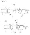
- FIG. 1 is a diagram showing the gas sensor 100 during assembling.
- FIG. 1(a) shows a state before the assembling
- FIG. 1(b) shows a state after the assembling.
- the gas sensor 100 has a structure in which a gas sensor main body 10 and a contact member 20 are integrated.
- the gas sensor main body 10 includes a sensor element 1 serving as a gas detection part, and a reception member 2 for receiving the sensor element 1.
- the contact member 20 mainly includes a plurality of contact-point members 21, lead wires 22 connected to the contact-point members 21, a ceramic-made housing 24 for holding the sensor element 1 inserted in an insertion port 23 with interposition of the contact-point members 21, and a grommet 28 formed so as to allow the lead wires 22 to be air-tightly inserted therethrough.
- the sensor element 1 included in the gas sensor main body 10 is inserted in the insertion port 23 of the housing 24 included in the contact member 20, and additionally the sensor element 1 is held in the housing 24 with interposition of the contact-point members 21, thereby forming the gas sensor 100 as an integrated part.
- FIG. 2 is a perspective view showing an outer shape of the sensor element 1.
- the sensor element 1 has a structure in which a plurality of oxygen-ion conductive solid electrolyte layers such as zirconia (ZrO 2 ) layers are laminated.
- the sensor element 1 has, on a surface and a back surface thereof, a plurality of electrode terminals 1a for applying a voltage, retrieving a detection signal, supplying power to a heater part, and the like.
- four electrode terminals 1a are provided at one side (the electrode terminals 1a provided on the back surface are not shown).
- this is merely illustrative, and the number of electrode terminals 1a may be appropriately set in accordance with a structure of the sensor element 1.
- a gas inlet 3 for introducing a reference gas is provided in an end face Is at the side where the electrode terminals 1a are provided, and a measurement gas inlet (not shown) is provided in the other end.
- the sensor element 1 is manufactured by, for example, performing a predetermined process and printing a pattern of electrodes and circuits on ceramic green sheets, each of which corresponds to each of the layers, then laminating the green sheets, cutting a resulting laminated body into a predetermined size, and then baking a resulting laminated body.
- the objective gas component is detected by utilizing the fact that a current corresponding to the amount of objective gas component in the measurement gas flows between predetermined electrodes at a time of introducing the measurement gas into the sensor element 1.
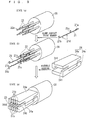
- FIGs. 3 and 4 are diagrams schematically showing a process of assembling the contact member 20.
- This process of assembling the contact member 20 is preliminary performed before the gas sensor main body 10 and the contact member 20 are integrated with each other.
- the process of assembling the contact member 20 will be referred to as "pre-assembling process” and this assembling will be also referred to as "pre-assembling”.
- the lead wires 22 are inserted through the grommet 28, as shown in a state (a) of FIG. 3 .
- a pressure-bonding portion 21a of the contact-point member 21 is connected to a distal end portion 22a of each lead wire 22. This connection is achieved by clamping the pressure-bonding portion 21a from the outside while the distal end portion 22a of the lead wire 22 is sandwiched in the pressure-bonding portion 21a.
- the contact-point members 21 are connected to only two lead wires 22, but actually, the contact-point members 21 are connected to all of the lead wires 22.
- the housing 24 is assembled as shown in a state (c) of FIG. 3 .
- the housing 24 includes a pair of housing members 24a arranged opposed to each other, and the assembling of the housing 24 is achieved by a first latch portion 21b and a second latch portion 21c of the contact-point member 21 being latched to predetermined positions in the housing members 24a.
- the first latch portion 21b is latched to a first latched portion 241 provided at one end portion of the housing member 24a. Therefore, the shapes of the first latch portion 21b and the first latched portion 241 are determined such that their latch state can be successfully maintained. That is, the first latch portion 21b is formed into a shape that matches a side-cross-sectional shape of the first latched portion 241.
- the second latch portion 21c is inserted and fitted into a second latched portion (not shown) provided in a middle portion of the housing member 24a, and thereby latched to the housing member 24a.
- the housing members 24a have substantially the same cross-sectional shape, and in assembling, they are spaced apart from each other such that a space having a rectangular shape in a cross-sectional view can be formed therebetween to serve as the insertion port 23.
- a gap 24b is formed at end portions of the two housing members 24a.
- the housing members 24a are shaped as if a housing defining a space therein and having a rectangular shape in a cross-sectional shape is divided into two pieces.
- each housing member 24a Assembling in the above-described manner enables a distal end portion and its neighborhood (near an end portion of the insertion port 23) of each housing member 24a to be deviated upward or downward within a predetermined range when an external force acting from the inside of the insertion port 23 toward the upper or lower side of the drawing sheet of FIG. 3 .
- the pair of housing members 24a receive the external force to sandwich the sensor element 1 in the insertion port 23, and thus the sensor element 1 is fixed to the contact member.
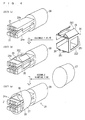
- a fixture 25 having pressure springs 26 fixed thereto in advance is also assembled to the outside of the housing 24.
- the pressure spring 26 is a leaf spring member shaped into a trapezoidal shape having no upper base in a cross-sectional view. When the external force is applied to a free end 261 of the pressure spring 26, the pressure spring 26 generates an elastic force as its resilient force.
- the fixture 25 not only serves to fix the pressure springs 26 but also serves to maintain a state where the housing 24 is assembled and more specifically a state where the insertion port 23 is formed, until the sensor element 1 is fixed in a sandwiched manner.
- the fixture 25 is a restraint member for restraining the pair of housing members 24a within a predetermined position range such that the state where the insertion port 23 is formed can be maintained. Assembling the fixture 25 together with the housing 24 can prevent occurrence of misalignment between the each contact-point member 21 (and more specifically a protrusion 21d) and a corresponding electrode terminal 1a of the sensor element 1 when the sensor element 1 is fixed. That is, it can be considered that the fixture 25 also serves to restrain the position range of the sensor element 1 at a time of fixing and sandwiching.
- the fixture 25 has a characteristic structure. Details of the fixture 25 will be described later.
- a clamping ring 27 which is an annular (cylindrical) member is assembled, as shown in a state (e).
- the state (e) shows a state after the contact member 20 is assembled.
- the clamping ring 27 is clamped after the pre-assembling and at a time of integrating the gas sensor main body 10 and the contact member 20 with each other, while the sensor element 1 is inserted in the insertion port 23 of the housing 24.
- the clamping ring 27 is shrinkingly deformed by an external force.
- a gap of the insertion port 23 of the housing 24 is reduced so that the sensor element 1 is biased from two directions, that is, from upper and lower sides thereof, due to the contact-point members 21 (and more specifically the protrusions 21d) included in the respective housing members 24a.
- the protrusion 21d of each contact-point member 21 is brought into contact with a corresponding electrode terminal 1a, and therefore electrical conduction between the sensor element 1 and the outside can be achieved through the lead wire 22 connected to the contact-point member 21.
- the gas sensor 100 according to this embodiment is characterized by the structure of the fixture 25, as described above. A more specific description of a configuration of the fixture 25 will be given below.
- FIG. 5 is a perspective view showing the structure of the fixture 25 according to this embodiment.
- the fixture 25 is configured as one piece including a first side portion 251 having a rectangular opening 252, two upper and lower pressing surface portions 253 coupled perpendicularly to the first side portion 251, and a second side portion 254 opposed to the first side portion 251.
- the second side portion 254 is divided into an upper side portion 254a and a lower side portion 254b, which have a spaced portion 255 interposed therebetween and each of which is coupled perpendicularly to each of the upper and lower pressing surface portions 253.
- the housing member 24a is restrained by the fixture 25 while being surrounded by the first side portion 251, the two pressing surface portions 253, and the second side portion 254.
- the opening 252 is formed such that its area ratio to the entire first side portion 251 is not less than 0.22.
- a state is achieved in which the sensor element 1 is uniformly sandwiched and fixed by the pair of housing members 24a (in more detail, by the contact-point members 21 latched to the housing members 24a). If the area ratio is less than 0.22, an effect of providing the opening 252 (details thereof will be described later) cannot be suitably obtained.
- an upper limit of the area ratio of the opening 252 to the entire first side portion 251 is put on a range that allows the two pressing surface portions 253 to be kept perpendicular to the first side portion 251 and that does not hinder the assembling of the fixture 25. Additionally, the upper limit varies depending on a material of the fixture 25.
- Providing the opening 252 means, in other words, that the first side portion 251 is continuous with the two upper and lower pressing surface portions 253 only in two end edge portions 251a provided at left and right sides of the opening 252.
- the two side portions of the fixture 25 are asymmetric.
- each of the pressing surface portions 253, the pressure spring 26 is held and fixed by a pair of holders 256 (only a part of which is shown in FIG. 5 ).
- an extension portion extending out of the pressing surface portion 253 is preliminary provided at an end portion of the pressing surface portion 253, and the extension portion is folded to thereby make a lower base portion of the pressure spring 26 sandwiched between the pressing surface portion 253 and the extension portion, thus holding the pressure spring 26.
- how to hold the pressure spring 26 by the fixture 25 is not limited thereto.
- the fixture 25 is made of a corrosion-resistant material (metal material).
- metal material metal material
- the strength is ensured to such a degree that the fixture 25 having the above-described structure can be suitably processed. Rather, from the viewpoint of suitably achieving a deformation behavior which will be described next, it is not necessary to adopt an excessively strong material.
- stainless steel such as SUS304
- the fixture 25 can be prepared by, for example, performing a known processing technique such as a folding process and a drilling process on a single metal plate made of the stainless steel or the like.
- FIG. 6 is a perspective view showing a main part of a conventional fixture 1025 for comparison. For simplification of the illustration, pressure springs and a part for holding them are not shown.
- the fixture 1025 shown in FIG. 6 has a configuration identical to that of the fixture 25 according to this embodiment, except that the opening 252 is not provided.
- FIG. 7 is a cross-sectional view schematically showing the contact member 20 as taken along the line A-A' of FIG. 6 before and after the clamping ring 27 is clamped, in a case where the contact member 20 is configured using the conventional fixture 1025.
- the contact-point members 21, the pressure springs 26, and the clamping ring 27 are not shown.
- the housing members 24a and the sensor element 1 are displaceable within a certain range (as indicated by the arrows in FIG. 7(a) ) though the housing members 24a and the sensor element 1 are restrained by the fixture 1025.
- the elastic force F1 occurring in the pressure springs 26 works as a force in a direction of compressing the fixture 1025, which acts on the two upper and lower pressing surface portions 253.
- the elastic force F1 occurring in the pressure springs 26 works as a force in a direction of compressing the fixture 1025, which acts on the two upper and lower pressing surface portions 253.
- the spaced portion 255 is narrowed to bring the upper side portion 254a and the lower side portion 254b closer to each other.
- the first side portion 251 is continuous with the two pressing surface portions 253, the first side portion 251 receives a compression force from two directions of the upper side and the lower side, so that the first side portion 251 deforms into a convex shape toward the outside of the fixture 1025, as shown in FIG. 7(b) .
- the sensor element 1 is contacted and fixed under pressure by the contact-point members 21 in a state that a reaction force F3 reactive to the compressive deformation occurs near the first side portion 251 and the elastic force applied from the contact-point members 21 to the sensor element 1 and its resistance force F2 vary in the magnitude among the individual contact-point members 21. That is, a slanted-load state occurs in which non-uniform loads are applied to the individual contact-point members 21. In this slanted-load state, contacts between the contact-point members 21 and the electrode terminals 1a of the sensor element 1 are not uniform, and a contact-point failure may occur at the contact-point member 21 having the protrusion 21d thereof largely deformed because of an excessive load.
- such a slanted-load state may cause a significant difference between the left and right opening degrees (distances) w1 and w2 of the two housing members 24a after the clamping, though not shown in detail in FIG. 7(b) .
- FIG. 8 is a perspective view showing a main part of the fixture 25 according to this embodiment.
- FIG. 9 is a cross-sectional view schematically showing of the contact member 20 as taken along the line B-B' of FIG. 8 , in a case where the contact member 20 configured using the fixture 25 according to this embodiment is clamped by the clamping ring 27.
- the housing members 24a and the sensor element 1 are displaceable within a certain range though the housing members 24a and the sensor element 1 are restrained by the fixture 25.
- the spaced portion 255 is narrowed to bring the upper side portion 254a and the lower side portion 254b closer to each other.
- the first side portion 251 in the case of the fixture 25, the first side portion 251 is not continuous with the two upper and lower pressing surface portions 253 in a cross-sectional position passing through the opening 252 as shown in FIG. 9 . Therefore, in the cross-sectional position, the compression force derived from the elastic force F1 does not act on the first side portion 251.
- the compression force acts only on the end edge portions 251a.
- most of the elastic force F1 concentrates on the end edge portions 251a. Therefore, the end edge portions 251a compressively deform without causing such a strong reaction force that is caused by the first side portion 251 of the conventional fixture 1025.
- the compressive deformation of the end edge portions 251a narrows the gap of the fist opening 252 in the vertical direction.
- the fixture 25 is configured such that a vertical gap can be narrowed not only in the second side portion 254 having the spaced portion 255 but also in the first side portion 251 that is continuous with the pressing surface portion 253 and therefore receives the compression force from the upper and lower sides thereof when the elastic force F1 acts on the upper surface portion 253 at a time of the clamping.
- the structure in which the opening 252 is provided in the first side portion 251 of the fixture 25 can be considered as a structure (reaction-force suppressing structure) that suppresses occurrence of a reaction force reactive to the compression force.
- the above-mentioned requirement that the area ratio of the opening 252 to the entire first side portion 251 should be 0.22 or more is defined as a requirement for suitably suppressing a reaction force in the first side portion 251 so that the gap can be narrowed in the vertical direction to a degree equal to the second side portion 254.
- the end edge portions 251a of the first side portion 251 compressively deform in the above-described manner, and consequently the sensor element 1 is brought into contact with the contact-point members 21 provided to the housing members 24a, so that the sensor element 1 is contacted and fixed under pressure by the contact-point members 21.
- the end edge portions 251a are compressed with substantially no reaction force, so that, after the clamping, the first side portion 251 and the second side portion 254 shrink about the same degree from the pre-clamping state.
- the elastic force is substantially uniformly applied from the individual contact-point members 21 to the sensor element 1, and as a reaction thereof, the resistance force F2 is substantially uniformly applied from the sensor element 1 to the housing members 24a.
- the fixture 25 substantially has the pressing surface portion 253 thereof merely sandwiched between the pressure springs 26 and the housing members 24a. That is, a state is established in which the elastic force F1 from the pressure springs 26 is directly applied to the housing members 24a irrespective of the restraint made by the fixture 25. This means that a restraint function of the fixture 25 is disabled after the clamping ring 27 is clamped.
- an opening is provided in the first side portion of the fixture which receives the compression force from the upper and lower sides thereof at the time of clamping, to thereby suppress occurrence of the reaction force reactive to the compression force.
- This can suppress occurrence of a slanted load in the contact-point members of the contact member, so that a uniform and stable contact state is established between the contact-point members of the contact member and the electrode terminals of the sensor element. As a result, electrical conduction between the sensor element and the contact member is stably ensured.
- the reaction-force suppressing structure causing substantially no reaction force in the first side portion at the time of clamping is achieved by providing the single opening 252 having a rectangular shape.
- an embodiment having the reaction-force suppressing structure is not limited to the above-described embodiment.
- various modifications of the fixture having the reaction-force suppressing structure will be shown.
- FIG. 10 is a diagram showing both perspective views of outline structures of fixtures 125, 225, 325, and 425 according to modifications and deformation behaviors (Load-Deformation Curves) of the respective fixtures with respect to a load.
- Any of the fixtures 125, 225, 325, and 425 has a configuration identical to that of the fixture 25 according to the above-described embodiment, except that the shape of the first side portion 251 is different.
- the fixture 25 according to the above-described embodiment and the conventional fixture 1025 are also shown.
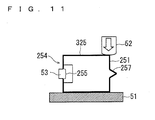
- FIG. 11 is a diagram schematically showing measurement of the deformation behavior of each of the fixtures shown in FIG. 10 .
- the deformation behavior is obtained by measuring the amount of deformation of the first side portion 251 at a time of, while placing the fixture on a predetermined stage 51, applying a load 52 from the upper side of the first side portion 251.
- the spaced portion 255 of the second side portion 254 is fixed by a fixing member 53. Therefore, a measurement result shown in FIG. 10 is different from a deformation behavior obtained when the clamping performed while the fixture is actually assembled.
- measurement conditions are the same with respect to all of the fixtures, whether the reaction-force suppressing structure in the first side portion 251 is relatively good or not can be determined based on the result shown in FIG. 10 .
- Each of the fixture 125 and the fixture 225 has two openings 252a and 252b at the first side portion 251.
- the openings 252a and 252b are provided such that a ratio of the total opening area to the entire first side portion 251 is not less than 0.22.
- the reaction force can be suitably suppressed in the first side portion 251 at the time of clamping.
- the fixture 325 has no opening, and instead, has a bent portion 257 that is formed by folding a part of the first side portion 251 so as to protrude outwardly.
- the fixture 325 configured in such a manner is used in the contact member 20
- the compression force acting on the first side portion 251 from the upper and lower sides thereof at the time of clamping is absorbed by the bent portion 257 shrinking in the vertical direction (compressively deforming).
- the reaction force reactive to the compression force is suppressed.
- the fixture 425 is configured so as to have both of the opening 252 and the bent portion 257.
- the compression force acting on the first side portion 251 from the upper and lower sides thereof at the time of clamping is absorbed by both the opening 252 and the bent portion 257. Thereby, the reaction force reactive to the compression force is suppressed.
- the value of a load reaches saturation at approximately 37 N at the maximum, while in the case of the conventional fixture 1025, the value does not reach saturation even at 40 N or more.
- the compressive deformation of the fixtures 25, 125, 225, 325, and 425 is caused by a smaller load as compared with the conventional fixture 1025.
- the fixture 25, 125, 225, 325, and 425 have a good compression-force absorbing structure Examples
- an NOx sensor was prepared by integrating the contact member 20 including the fixture 25 according to the above-described embodiment with the gas sensor main body 10, and thereafter, it was disassembled and heights h of the protrusions 21d of all the contact-point members 21 used in the contact member 20 were measured.
- the number of measured protrusions 21d was set to be 232 (the number of measured sensors was set to be 29).
- FIG. 12 is a diagram showing the height h of the protrusion 21d that was a measurement object.
- an NOx sensor was prepared and then the subsequent disassembling and measurement were performed similarly to the example.
- the number of measured protrusions 21d was 232 (the number of measured sensors was 29).
- FIG. 13 is a histogram showing a ratio of the height h to an initial value (fixed value) that was obtained before assembling with respect to the example and the comparative example. Referring to a result shown in FIG. 13 , the value is more uniform in the example than in the comparative example.
- the histogram of FIG. 13 includes all measurement results concerning the contact-point members 21 assembled at different locations in the contact member 20. Therefore, the above-described result indicates that a force acting on the contact-point members 21 assembled at different locations in the contact member 20 is more uniform in the example than in the comparative example.
- representative values (the median, the average, the mode) of a distribution are greater in the example than in the comparative example. Therefore, it can be considered that, generally, the degree of plastic deformation of the protrusion 21d is lower in the example than in the comparative example.
- This result means that fixing of the sensor element can be performed with a smaller force in the example than in the comparative example. This is because in the comparative example, it was necessary to apply an extra force in order to counteract a reaction force occurring in the first side portion 251 of the fixture 1025 at a time of fixing the sensor element, while in the example, a compression force occurring at a time of clamping was absorbed so that a reaction force hardly occurred, and therefore it was not necessary to apply an extra force.
- FIG. 14 is a diagram showing normal probability density curves of ⁇ w obtained based on results of these measurement. In FIG. 14 , each of the curves is signed with the reference numeral of the corresponding fixture.
Landscapes
- Chemical & Material Sciences (AREA)
- Life Sciences & Earth Sciences (AREA)
- Health & Medical Sciences (AREA)
- Physics & Mathematics (AREA)
- Chemical Kinetics & Catalysis (AREA)
- Electrochemistry (AREA)
- Molecular Biology (AREA)
- Analytical Chemistry (AREA)
- Biochemistry (AREA)
- General Health & Medical Sciences (AREA)
- General Physics & Mathematics (AREA)
- Immunology (AREA)
- Pathology (AREA)
- Measuring Oxygen Concentration In Cells (AREA)
Abstract
Description
- The present invention relates to a gas sensor for measuring a concentration of a predetermined gas component in a measurement gas, and particularly relates to a technique for holding and fixing a sensor element thereof.
- Conventionally, various measuring apparatuses have been used for recognizing a concentration of a desired gas component in a measurement gas. For example, as a device for measuring a NOx concentration in a measurement gas such as a combustion gas, known is a gas sensor (NOx sensor) having oxygen-ion conductivity, such as one made constituted by zirconia (ZrO2) (for example, see Patent Document 1). In such a gas sensor, in general, a sensor element has a plurality of electrode terminals formed on a surface thereof for applying a voltage, retrieving a detection signal, supplying power to a heater part, and the like.
- Here, the gas sensor includes a contact member for holding the sensor element inserted therein. For example, a gas sensor is already known having a contact member that includes: a housing in which an insertion port for insertion of a sensor element is defined by a pair of housing members arranged opposed to each other; a plurality of contact-point members configured as metal terminals provided on the housing member; and a plurality of lead wires connected to the contact-point members for electrical conduction between the sensor element and the outside (for example, see Patent Document 2).
- In the gas sensor disclosed in the
Patent Document 2, the contact member holds the sensor element inserted in the insertion port while making the contact-point members and electrode terminals in contact with each other, thereby obtaining electrical conduction between the sensor element and the outside. In other words, in the gas sensor disclosed in thePatent Document 2, the contact-point members serve as contact points with the electrode terminals. Specifically, in a state where the sensor element is inserted in the insertion port, the housing members are fitted into a fixture having a substantially concave shape (or substantially C-like shape) in a cross-sectional view and having pressure springs formed at upper and lower sides thereof, and additionally a clamping ring is arranged at an outer circumferences of the fixture and the pressure springs and then the clamping ring is clamped so that the pressure springs are displaced to bias the contact-point members to the electrode terminals due to an elastic force of the pressure springs, thus holding the sensor element and ensuring the electrical conduction. - Here, the fixture disclosed in the
Patent Document 2 not only serves to fix a spring member as described above but also serves to restrain the pair of housing members in a predetermined positional relationship until the sensor element is inserted in the insertion port and the clamping ring is clamped. This restraint is necessary for achieving a correct contact between each electrode terminal and a corresponding contact-point member without misalignment at the time of holding and fixing the sensor element between the pair of housing members (that is, in the insertion port) by clamping the clamping ring. In a case of thePatent Document 2, since the fixture has a concave shape in a cross-sectional view, an elasticity of the fixture serving as a leaf spring is utilized for holding and restraining the housing members. - In the gas sensor disclosed in the
Patent Document 2, the clamping ring is clamped so that the elastic force of the pressure springs is applied to the housing via the fixtures, thereby fixing the sensor element to the housing. At this time, the contact-point members provided on the housing bias the electrode terminals, and thereby the contact between the electrode terminals and the contact-point members is ensured. - Here, however, a problem arises that a force acting on the housing may be asymmetric (non-uniform) because the fixture has a concave shape in a cross-sectional view as described above. In a gas sensor configured to have a plurality of electrode terminals in contact with corresponding contact-point members, respectively, a biasing force of the contact-point member to the electrode terminal varies depending on positions due to the non-uniformity, which may consequently cause a local contact failure.
-
- Patent Document 1: Japanese Patent Application Laid-Open No.
2006-284223 - Patent Document 2: Japanese Patent Application Laid-Open No.
2002-168822 - The present invention is made in view of the problem described above, and an object of the present invention is to provide a gas sensor capable of stably ensuring electrical conduction between a sensor element and a contact member.
- To solve the above-described problem, in a fist aspect of the present invention, a contact member for a gas sensor configured to fix a sensor element by sandwiching the sensor element in an insertion port defined by a pair of housing members to thereby obtain electrical connection with the sensor element, the contact member includes: a restraint member provided at an outer circumference of the pair of housing members, the restraint member having a restraint function for restraining a displacement of the pair of housing members within a predetermined range; and an annular member provided at an outer circumference of the restraint member. A compression force, which occurs when the annular member shrinkingly deforms by receiving an external force with the sensor element inserted in the insertion port, is applied through the restraint member to thereby contact the pair of housing members with the sensor element under pressure, so that the sensor element is fixed by being sandwiched between the pair of housing members in a state that an electrode terminal provided on the sensor element and a contact-point member provided on the pair of housing members are in contact with each other. The restraint member includes: two pressing surface portions to which the compression force that occurs when the annular member shrinkingly deforms is applied; a first side portion coupled perpendicularly to the two pressing surface portions; and a second side portion having an upper side portion coupled perpendicularly to one of the two pressing surfaces and a lower side portion coupled perpendicularly to the other of the two pressing surfaces, the second side portion also having a spaced portion provided between the upper side portion and the lower side portion. The first side portion has a reaction-force suppressing structure for suppressing occurrence of a reaction force reactive to the compression force.
- In a second aspect of the present invention, in the contact member for a gas sensor according to the fist aspect, the first side portion has at least one opening, and the reaction force is suppressed by causing an end edge portion located lateral to the opening to compressively deform due to the compression force.
- In a third aspect of the present invention, in the contact member for a gas sensor according to the fist aspect, the first side portion has a bent portion, and the reaction force is suppressed by causing the bent portion to compressively deform due to the compression force.
- In a fourth aspect of the present invention, in the contact member for a gas sensor according to the fist aspect, the first side portion has at least one opening and also has a bent portion formed at an end edge portion located lateral to the opening, and the reaction force is suppressed by causing the end edge portion including the bent portion to compressively deform.
- In a fifth aspect of the present invention, a gas sensor includes a sensor element, and the contact member for a gas sensor according to any one of the first to fourth aspects.
- In a sixth aspect of the present invention, the restraint member is for use in the contact member for a gas sensor according to any one of the first to fourth aspects.
- In a seventh aspect of the present invention, a method for connecting a contact member with a sensor element in a gas sensor includes the steps of: preparing a contact member, the contact meter including a pair of housing member arranged so as to define an insertion port for insertion of the sensor element, a restraint member provided at an outer circumference of the pair of housing members, the restraint member having a restraint function for restraining a displacement of the pair of housing members within a predetermined range, and an annular member provided at an outer circumference of the restraint member; inserting the sensor element into the insertion port; and applying an external force to the annular member to cause the annular member to shrinkingly deform to thereby contact the pair of housing members with the sensor element under pressure, so that the sensor element is fixed by being sandwiched between the pair of housing members in a state that an electrode terminal provided on the sensor element and a contact-point member provided on the pair of housing members are in contact with each other. The restraint member includes: two pressing surface portions to which a compression force that occurs when the annular member shrinkingly deforms is applied; a first side portion coupled perpendicularly to the two pressing surface portions; and a second side portion having an upper side portion coupled perpendicularly to one of the two pressing surfaces and a lower side portion coupled perpendicularly to the other of the two pressing surfaces, the second side portion also having a spaced portion provided between the upper side portion and the lower side portion. The first side portion has a reaction-force suppressing structure for suppressing occurrence of a reaction force reactive to the compression force.
- In an eighth aspect of the present invention, in the method for connecting a contact member with a sensor element according to the seventh aspect, the first side portion has at least one opening, and the reaction force is suppressed by causing an end edge portion located lateral to the opening to compressively deform due to the compression force.
- In an ninth aspect of the present invention, in the method for connecting a contact member with a sensor element according to the seventh aspect, the first side portion has a bent portion, and the reaction force is suppressed by causing the bent portion to compressively deform due to the compression force.
- In a tenth aspect of the present invention, in the method for connecting a contact member with a sensor element according to the seventh aspect, the first side portion has at least one opening and also has a bent portion formed at an end edge portion located lateral to the opening, and the reaction force is suppressed by causing the end edge portion including the bent portion to compressively deform.
- In an eleventh aspect of the present invention, a method for manufacturing a gas sensor includes the steps of: arranging a pair of housing members so as to define an insertion port for insertion of a sensor element; providing a restraint member at an outer circumference of the pair of housing members, the restraint member having a restraint function for restraining a displacement of the pair of housing members within a predetermined range; providing an annular member at an outer circumference of the restraint member; inserting the sensor element into the insertion port; and applying an external force to the annular member to cause the annular member to shrinkingly deform to thereby contact the pair of housing members with the sensor element under pressure, so that the sensor element is fixed by being sandwiched between the pair of housing members in a state that an electrode terminal provided on the sensor element and a contact-point member provided on the pair of housing members are in contact with each other. The restraint member includes: two pressing surface portions to which a compression force that occurs when the annular member shrinkingly deforms is applied; a first side portion coupled perpendicularly to the two pressing surface portions; and a second side portion having an upper side portion coupled perpendicularly to one of the two pressing surfaces and a lower side portion coupled perpendicularly to the other of the two pressing surfaces, the second side portion also having a spaced portion provided between the upper side portion and the lower side portion. The first side portion has a reaction-force suppressing structure for suppressing occurrence of a reaction force reactive to the compression force.
- In a twelfth aspect of the present invention, in the method for manufacturing a gas sensor according to the eleventh aspect, the first side portion has at least one opening, and the reaction force is suppressed by causing an end edge portion located lateral to the opening to compressively deform due to the compression force.
- In a thirteenth aspect of the present invention, in the method for manufacturing a gas sensor according to the eleventh aspect, the first side portion has a bent portion, and the reaction force is suppressed by causing the bent portion to compressively deform due to the compression force.
- In a fourteenth aspect of the present invention, in the method for manufacturing a gas sensor according to the eleventh aspect, the first side portion has at least one opening and also has a bent portion formed at an end edge portion located lateral to the opening, and the reaction force is suppressed by causing the end edge portion including the bent portion to compressively deform.
- In a fifteenth aspect of the present invention, a gas sensor is manufactured by the method for manufacturing a gas sensor according to any one of the eleventh to fourteenth aspects.
- According to the first to fifteenth aspects of the present invention, in the restraint member, the reaction-force suppressing structure is provided at the first side portion to which the compression force is applied from upper and lower sides thereof at a time of clamping. This suppresses occurrence of a slanted load in the contact-point member of the contact member, and therefore a uniform and stable contact state can be established between the contact-point member of the contact member and the electrode terminal of the sensor element.
-
- [
FIG. 1 ] A diagram showing assembling of agas sensor 100. - [
FIG. 2 ] A perspective view showing an outer shape of asensor element 1. - [
FIG. 3 ] A diagram schematically showing a process of assembling acontact member 20. - [
FIG. 4 ] A diagram schematically showing the process of assembling thecontact member 20. - [
FIG. 5 ] A perspective view showing a structure of afixture 25 according to this embodiment. - [
FIG. 6 ] A perspective view showing a main part of aconventional fixture 1025. - [
FIG. 7 ] A cross-sectional view schematically showing thecontact member 20 as taken along the line A-A' ofFIG. 6 . - [
FIG. 8 ] A perspective view showing a main part of thefixture 25 according to this embodiment. - [
FIG. 9 ] A cross-sectional view schematically showing thecontact member 20 as taken along the line B-B' ofFIG. 8 . - [
FIG. 10 ] A diagram showing both perspective views of outline structures of fixtures according to modifications and deformation behaviors of the respective fixtures. - [
FIG. 11 ] A diagram schematically showing measurement of the deformation behavior of the fixture. - [
FIG. 12 ] A diagram showing the height h of aprotrusion 21d. - [
FIG. 13 ] A histogram showing a ratio of the height h to an initial value that was obtained before assembling with respect to an example and a comparative example. - [
FIG. 14 ] A diagram showing a normal probability density curve of a difference Δw between left and right opening degrees ofhousing members 24a. - Firstly, an outline structure of a
gas sensor 100 will be described. Thegas sensor 100 is for detecting a predetermined gas component (objective gas component) in a gas (measurement gas) to be measured, and further measuring a concentration thereof.FIG. 1 is a diagram showing thegas sensor 100 during assembling.FIG. 1(a) shows a state before the assembling, andFIG. 1(b) shows a state after the assembling. - The
gas sensor 100 has a structure in which a gas sensormain body 10 and acontact member 20 are integrated. The gas sensormain body 10 includes asensor element 1 serving as a gas detection part, and areception member 2 for receiving thesensor element 1. On the other hand, thecontact member 20 mainly includes a plurality of contact-point members 21,lead wires 22 connected to the contact-point members 21, a ceramic-madehousing 24 for holding thesensor element 1 inserted in aninsertion port 23 with interposition of the contact-point members 21, and agrommet 28 formed so as to allow thelead wires 22 to be air-tightly inserted therethrough. - As shown in
FIG. 1(b) , thesensor element 1 included in the gas sensormain body 10 is inserted in theinsertion port 23 of thehousing 24 included in thecontact member 20, and additionally thesensor element 1 is held in thehousing 24 with interposition of the contact-point members 21, thereby forming thegas sensor 100 as an integrated part. -
FIG. 2 is a perspective view showing an outer shape of thesensor element 1. Thesensor element 1 has a structure in which a plurality of oxygen-ion conductive solid electrolyte layers such as zirconia (ZrO2) layers are laminated. Thesensor element 1 has, on a surface and a back surface thereof, a plurality ofelectrode terminals 1a for applying a voltage, retrieving a detection signal, supplying power to a heater part, and the like. In thesensor element 1 shown inFIG. 2 , fourelectrode terminals 1a are provided at one side (theelectrode terminals 1a provided on the back surface are not shown). However, this is merely illustrative, and the number ofelectrode terminals 1a may be appropriately set in accordance with a structure of thesensor element 1. In thesensor element 1, a gas inlet 3 for introducing a reference gas is provided in an end face Is at the side where theelectrode terminals 1a are provided, and a measurement gas inlet (not shown) is provided in the other end. - The
sensor element 1 is manufactured by, for example, performing a predetermined process and printing a pattern of electrodes and circuits on ceramic green sheets, each of which corresponds to each of the layers, then laminating the green sheets, cutting a resulting laminated body into a predetermined size, and then baking a resulting laminated body. In thegas sensor 100, the objective gas component is detected by utilizing the fact that a current corresponding to the amount of objective gas component in the measurement gas flows between predetermined electrodes at a time of introducing the measurement gas into thesensor element 1. - Next, a detailed configuration of the
contact member 20 will be described with showing an assembling process thereof.FIGs. 3 and4 are diagrams schematically showing a process of assembling thecontact member 20. This process of assembling thecontact member 20 is preliminary performed before the gas sensormain body 10 and thecontact member 20 are integrated with each other. In this sense, the process of assembling thecontact member 20 will be referred to as "pre-assembling process" and this assembling will be also referred to as "pre-assembling". - In the pre-assembling of the
contact member 20, firstly, thelead wires 22 are inserted through thegrommet 28, as shown in a state (a) ofFIG. 3 . Then, as shown in a state (b), a pressure-bonding portion 21a of the contact-point member 21 is connected to adistal end portion 22a of eachlead wire 22. This connection is achieved by clamping the pressure-bonding portion 21a from the outside while thedistal end portion 22a of thelead wire 22 is sandwiched in the pressure-bonding portion 21a. In the state (b), for simplification of the illustration, the contact-point members 21 are connected to only twolead wires 22, but actually, the contact-point members 21 are connected to all of thelead wires 22. - After the contact-
point members 21 are connected, then thehousing 24 is assembled as shown in a state (c) ofFIG. 3 . In more detail, thehousing 24 includes a pair ofhousing members 24a arranged opposed to each other, and the assembling of thehousing 24 is achieved by afirst latch portion 21b and asecond latch portion 21c of the contact-point member 21 being latched to predetermined positions in thehousing members 24a. - More specifically, the
first latch portion 21b is latched to a first latchedportion 241 provided at one end portion of thehousing member 24a. Therefore, the shapes of thefirst latch portion 21b and the first latchedportion 241 are determined such that their latch state can be successfully maintained. That is, thefirst latch portion 21b is formed into a shape that matches a side-cross-sectional shape of the first latchedportion 241. On the other hand, thesecond latch portion 21c is inserted and fitted into a second latched portion (not shown) provided in a middle portion of thehousing member 24a, and thereby latched to thehousing member 24a. - Here, the
housing members 24a have substantially the same cross-sectional shape, and in assembling, they are spaced apart from each other such that a space having a rectangular shape in a cross-sectional view can be formed therebetween to serve as theinsertion port 23. For this purpose, agap 24b is formed at end portions of the twohousing members 24a. In other words, thehousing members 24a are shaped as if a housing defining a space therein and having a rectangular shape in a cross-sectional shape is divided into two pieces. Assembling in the above-described manner enables a distal end portion and its neighborhood (near an end portion of the insertion port 23) of eachhousing member 24a to be deviated upward or downward within a predetermined range when an external force acting from the inside of theinsertion port 23 toward the upper or lower side of the drawing sheet ofFIG. 3 . The pair ofhousing members 24a receive the external force to sandwich thesensor element 1 in theinsertion port 23, and thus thesensor element 1 is fixed to the contact member. - In assembling the
housing 24, as shown in a state (d) ofFIG. 4 , afixture 25 having pressure springs 26 fixed thereto in advance is also assembled to the outside of thehousing 24. - The
pressure spring 26 is a leaf spring member shaped into a trapezoidal shape having no upper base in a cross-sectional view. When the external force is applied to afree end 261 of thepressure spring 26, thepressure spring 26 generates an elastic force as its resilient force. - The
fixture 25 not only serves to fix the pressure springs 26 but also serves to maintain a state where thehousing 24 is assembled and more specifically a state where theinsertion port 23 is formed, until thesensor element 1 is fixed in a sandwiched manner. In other words, thefixture 25 is a restraint member for restraining the pair ofhousing members 24a within a predetermined position range such that the state where theinsertion port 23 is formed can be maintained. Assembling thefixture 25 together with thehousing 24 can prevent occurrence of misalignment between the each contact-point member 21 (and more specifically aprotrusion 21d) and acorresponding electrode terminal 1a of thesensor element 1 when thesensor element 1 is fixed. That is, it can be considered that thefixture 25 also serves to restrain the position range of thesensor element 1 at a time of fixing and sandwiching. - In the
gas sensor 100 according to this embodiment, thefixture 25 has a characteristic structure. Details of thefixture 25 will be described later. - After the
fixture 25 is assembled, a clampingring 27 which is an annular (cylindrical) member is assembled, as shown in a state (e). Through the above-described steps, the pre-assembling is completed. Thus, the state (e) shows a state after thecontact member 20 is assembled. - The clamping
ring 27 is clamped after the pre-assembling and at a time of integrating the gas sensormain body 10 and thecontact member 20 with each other, while thesensor element 1 is inserted in theinsertion port 23 of thehousing 24. In other words, the clampingring 27 is shrinkingly deformed by an external force. As a result, a gap of theinsertion port 23 of thehousing 24 is reduced so that thesensor element 1 is biased from two directions, that is, from upper and lower sides thereof, due to the contact-point members 21 (and more specifically theprotrusions 21d) included in therespective housing members 24a. Thus, a state where thesensor element 1 is fixed while being sandwiched between the pair ofhousing members 24a is achieved. At this time, theprotrusion 21d of each contact-point member 21 is brought into contact with a correspondingelectrode terminal 1a, and therefore electrical conduction between thesensor element 1 and the outside can be achieved through thelead wire 22 connected to the contact-point member 21. - The
gas sensor 100 according to this embodiment is characterized by the structure of thefixture 25, as described above. A more specific description of a configuration of thefixture 25 will be given below. -
FIG. 5 is a perspective view showing the structure of thefixture 25 according to this embodiment. In outline, thefixture 25 is configured as one piece including afirst side portion 251 having arectangular opening 252, two upper and lowerpressing surface portions 253 coupled perpendicularly to thefirst side portion 251, and asecond side portion 254 opposed to thefirst side portion 251. Thesecond side portion 254 is divided into anupper side portion 254a and alower side portion 254b, which have a spacedportion 255 interposed therebetween and each of which is coupled perpendicularly to each of the upper and lowerpressing surface portions 253. In assembling thecontact member 20, thehousing member 24a is restrained by thefixture 25 while being surrounded by thefirst side portion 251, the twopressing surface portions 253, and thesecond side portion 254. - The
opening 252 is formed such that its area ratio to the entirefirst side portion 251 is not less than 0.22. In such a case, after theclamping ring 27 is clamped, a state is achieved in which thesensor element 1 is uniformly sandwiched and fixed by the pair ofhousing members 24a (in more detail, by the contact-point members 21 latched to thehousing members 24a). If the area ratio is less than 0.22, an effect of providing the opening 252 (details thereof will be described later) cannot be suitably obtained. No particular limitation is put on an upper limit of the area ratio of theopening 252 to the entirefirst side portion 251, as long as it is within a range that allows the twopressing surface portions 253 to be kept perpendicular to thefirst side portion 251 and that does not hinder the assembling of thefixture 25. Additionally, the upper limit varies depending on a material of thefixture 25. - Providing the
opening 252 means, in other words, that thefirst side portion 251 is continuous with the two upper and lowerpressing surface portions 253 only in twoend edge portions 251a provided at left and right sides of theopening 252. - Since the
first side portion 251 and thesecond side portion 254 have different shapes, it can be said that the two side portions of thefixture 25 are asymmetric. - In each of the
pressing surface portions 253, thepressure spring 26 is held and fixed by a pair of holders 256 (only a part of which is shown inFIG. 5 ). In this embodiment, an extension portion extending out of thepressing surface portion 253 is preliminary provided at an end portion of thepressing surface portion 253, and the extension portion is folded to thereby make a lower base portion of thepressure spring 26 sandwiched between thepressing surface portion 253 and the extension portion, thus holding thepressure spring 26. However, how to hold thepressure spring 26 by thefixture 25 is not limited thereto. - It is necessary that the
fixture 25 is made of a corrosion-resistant material (metal material). In terms of the strength of the material, it suffices that the strength is ensured to such a degree that thefixture 25 having the above-described structure can be suitably processed. Rather, from the viewpoint of suitably achieving a deformation behavior which will be described next, it is not necessary to adopt an excessively strong material. Although there is no specific restriction on the material, stainless steel (such as SUS304) may be mentioned as a preferable example. Thefixture 25 can be prepared by, for example, performing a known processing technique such as a folding process and a drilling process on a single metal plate made of the stainless steel or the like. - Next, effects obtained by adopting the above-described configuration in the
fixture 25 will be described. As will be detailed later, the effects are obtained in a phase of integrating the gas sensormain body 10 and thecontact member 20 with each other. -
FIG. 6 is a perspective view showing a main part of aconventional fixture 1025 for comparison. For simplification of the illustration, pressure springs and a part for holding them are not shown. Thefixture 1025 shown inFIG. 6 has a configuration identical to that of thefixture 25 according to this embodiment, except that theopening 252 is not provided. -
FIG. 7 is a cross-sectional view schematically showing thecontact member 20 as taken along the line A-A' ofFIG. 6 before and after theclamping ring 27 is clamped, in a case where thecontact member 20 is configured using theconventional fixture 1025. For simplification of the illustration, the contact-point members 21, the pressure springs 26, and the clampingring 27 are not shown. - As shown in
FIG. 7(a) , in a state before the clamping, thehousing members 24a and thesensor element 1 are displaceable within a certain range (as indicated by the arrows inFIG. 7(a) ) though thehousing members 24a and thesensor element 1 are restrained by thefixture 1025. - If the clamping
ring 27 is clamped so that an elastic force F1 is applied from the pressure springs 26 to thefixture 1025, as shown inFIG. 7(b) , the elastic force F1 occurring in the pressure springs 26 works as a force in a direction of compressing thefixture 1025, which acts on the two upper and lowerpressing surface portions 253. At this time, in thesecond side portion 254 in which theupper side portion 254a and thelower side portion 254b are spaced apart from each other, no reaction force occurs and the spacedportion 255 is narrowed to bring theupper side portion 254a and thelower side portion 254b closer to each other. - On the other hand, the
first side portion 251 is continuous with the twopressing surface portions 253, thefirst side portion 251 receives a compression force from two directions of the upper side and the lower side, so that thefirst side portion 251 deforms into a convex shape toward the outside of thefixture 1025, as shown inFIG. 7(b) . - As a result, after the clamping, the
sensor element 1 is contacted and fixed under pressure by the contact-point members 21 in a state that a reaction force F3 reactive to the compressive deformation occurs near thefirst side portion 251 and the elastic force applied from the contact-point members 21 to thesensor element 1 and its resistance force F2 vary in the magnitude among the individual contact-point members 21. That is, a slanted-load state occurs in which non-uniform loads are applied to the individual contact-point members 21. In this slanted-load state, contacts between the contact-point members 21 and theelectrode terminals 1a of thesensor element 1 are not uniform, and a contact-point failure may occur at the contact-point member 21 having theprotrusion 21d thereof largely deformed because of an excessive load. - Additionally, such a slanted-load state may cause a significant difference between the left and right opening degrees (distances) w1 and w2 of the two
housing members 24a after the clamping, though not shown in detail inFIG. 7(b) . -
FIG. 8 is a perspective view showing a main part of thefixture 25 according to this embodiment.FIG. 9 is a cross-sectional view schematically showing of thecontact member 20 as taken along the line B-B' ofFIG. 8 , in a case where thecontact member 20 configured using thefixture 25 according to this embodiment is clamped by the clampingring 27. - Although not shown, in a case where the
contact member 20 is configured using thefixture 25 according to this embodiment, similarly to the case of using theconventional fixture 1025, in a state before the clamping, thehousing members 24a and thesensor element 1 are displaceable within a certain range though thehousing members 24a and thesensor element 1 are restrained by thefixture 25. - Next, a case of clamping the clamping
ring 27 will be considered. Firstly, in thesecond side portion 254, similarly to in the case offixture 1025, the spacedportion 255 is narrowed to bring theupper side portion 254a and thelower side portion 254b closer to each other. - As for the
first side portion 251, on the other hand, in the case of thefixture 25, thefirst side portion 251 is not continuous with the two upper and lowerpressing surface portions 253 in a cross-sectional position passing through theopening 252 as shown inFIG. 9 . Therefore, in the cross-sectional position, the compression force derived from the elastic force F1 does not act on thefirst side portion 251. The compression force acts only on theend edge portions 251a. Thus, most of the elastic force F1 concentrates on theend edge portions 251a. Therefore, theend edge portions 251a compressively deform without causing such a strong reaction force that is caused by thefirst side portion 251 of theconventional fixture 1025. The compressive deformation of theend edge portions 251a narrows the gap of thefist opening 252 in the vertical direction. - Thus, the
fixture 25 is configured such that a vertical gap can be narrowed not only in thesecond side portion 254 having the spacedportion 255 but also in thefirst side portion 251 that is continuous with thepressing surface portion 253 and therefore receives the compression force from the upper and lower sides thereof when the elastic force F1 acts on theupper surface portion 253 at a time of the clamping. In other words, the structure in which theopening 252 is provided in thefirst side portion 251 of thefixture 25 can be considered as a structure (reaction-force suppressing structure) that suppresses occurrence of a reaction force reactive to the compression force. The above-mentioned requirement that the area ratio of theopening 252 to the entirefirst side portion 251 should be 0.22 or more is defined as a requirement for suitably suppressing a reaction force in thefirst side portion 251 so that the gap can be narrowed in the vertical direction to a degree equal to thesecond side portion 254. - The
end edge portions 251a of thefirst side portion 251 compressively deform in the above-described manner, and consequently thesensor element 1 is brought into contact with the contact-point members 21 provided to thehousing members 24a, so that thesensor element 1 is contacted and fixed under pressure by the contact-point members 21. As described above, theend edge portions 251a are compressed with substantially no reaction force, so that, after the clamping, thefirst side portion 251 and thesecond side portion 254 shrink about the same degree from the pre-clamping state. Thus, the elastic force is substantially uniformly applied from the individual contact-point members 21 to thesensor element 1, and as a reaction thereof, the resistance force F2 is substantially uniformly applied from thesensor element 1 to thehousing members 24a. That is, a uniform and stable contact state is established between the contact-point members 21 of the contact member and theelectrode terminals 1a of the sensor element, and no slanted load occurs. Accordingly, the difference between the left and right opening degrees w1 and w2 of the twohousing members 24a is also reduced as compared with the case of using theconventional fixture 1025. - From another viewpoint, after the
clamping ring 27 is clamped, thefixture 25 substantially has thepressing surface portion 253 thereof merely sandwiched between the pressure springs 26 and thehousing members 24a. That is, a state is established in which the elastic force F1 from the pressure springs 26 is directly applied to thehousing members 24a irrespective of the restraint made by thefixture 25. This means that a restraint function of thefixture 25 is disabled after theclamping ring 27 is clamped. - As described above, in this embodiment, an opening is provided in the first side portion of the fixture which receives the compression force from the upper and lower sides thereof at the time of clamping, to thereby suppress occurrence of the reaction force reactive to the compression force. This can suppress occurrence of a slanted load in the contact-point members of the contact member, so that a uniform and stable contact state is established between the contact-point members of the contact member and the electrode terminals of the sensor element. As a result, electrical conduction between the sensor element and the contact member is stably ensured.
- In the above-described embodiment, the reaction-force suppressing structure causing substantially no reaction force in the first side portion at the time of clamping is achieved by providing the
single opening 252 having a rectangular shape. However, an embodiment having the reaction-force suppressing structure is not limited to the above-described embodiment. Hereinafter, various modifications of the fixture having the reaction-force suppressing structure will be shown. -
FIG. 10 is a diagram showing both perspective views of outline structures offixtures fixtures fixture 25 according to the above-described embodiment, except that the shape of thefirst side portion 251 is different. InFIG. 10 , for comparison, thefixture 25 according to the above-described embodiment and theconventional fixture 1025 are also shown. -
FIG. 11 is a diagram schematically showing measurement of the deformation behavior of each of the fixtures shown inFIG. 10 . InFIG. 11 , a case where thefixture 325 is to be measured is shown as an example. The deformation behavior is obtained by measuring the amount of deformation of thefirst side portion 251 at a time of, while placing the fixture on apredetermined stage 51, applying aload 52 from the upper side of thefirst side portion 251. In this measurement, the spacedportion 255 of thesecond side portion 254 is fixed by a fixingmember 53. Therefore, a measurement result shown inFIG. 10 is different from a deformation behavior obtained when the clamping performed while the fixture is actually assembled. However, since measurement conditions are the same with respect to all of the fixtures, whether the reaction-force suppressing structure in thefirst side portion 251 is relatively good or not can be determined based on the result shown inFIG. 10 . - Each of the
fixture 125 and thefixture 225 has twoopenings first side portion 251. In thesefixtures openings first side portion 251 is not less than 0.22. Thereby, similarly to the above-described embodiment, the reaction force can be suitably suppressed in thefirst side portion 251 at the time of clamping. - The
fixture 325 has no opening, and instead, has abent portion 257 that is formed by folding a part of thefirst side portion 251 so as to protrude outwardly. In a case where thefixture 325 configured in such a manner is used in thecontact member 20, the compression force acting on thefirst side portion 251 from the upper and lower sides thereof at the time of clamping is absorbed by thebent portion 257 shrinking in the vertical direction (compressively deforming). Thereby, the reaction force reactive to the compression force is suppressed. - The
fixture 425 is configured so as to have both of theopening 252 and thebent portion 257. In a case where thefixture 425 is used in thecontact member 20, the compression force acting on thefirst side portion 251 from the upper and lower sides thereof at the time of clamping is absorbed by both theopening 252 and thebent portion 257. Thereby, the reaction force reactive to the compression force is suppressed. - Referring to
FIG. 10 , in the cases of thefixtures conventional fixture 1025, the value does not reach saturation even at 40 N or more. This means that the compressive deformation of thefixtures conventional fixture 1025. Thus, the result suggests that thefixtures - In an example 1, an NOx sensor was prepared by integrating the
contact member 20 including thefixture 25 according to the above-described embodiment with the gas sensormain body 10, and thereafter, it was disassembled and heights h of theprotrusions 21d of all the contact-point members 21 used in thecontact member 20 were measured. The number of measuredprotrusions 21d was set to be 232 (the number of measured sensors was set to be 29).FIG. 12 is a diagram showing the height h of theprotrusion 21d that was a measurement object. - In a comparative example, using a contact member that includes the
fixture 1025 having the same structure as that of thefixture 25 according to the example except that theopening 252 is not provided, an NOx sensor was prepared and then the subsequent disassembling and measurement were performed similarly to the example. The number of measuredprotrusions 21d was 232 (the number of measured sensors was 29). -
FIG. 13 is a histogram showing a ratio of the height h to an initial value (fixed value) that was obtained before assembling with respect to the example and the comparative example. Referring to a result shown inFIG. 13 , the value is more uniform in the example than in the comparative example. The histogram ofFIG. 13 includes all measurement results concerning the contact-point members 21 assembled at different locations in thecontact member 20. Therefore, the above-described result indicates that a force acting on the contact-point members 21 assembled at different locations in thecontact member 20 is more uniform in the example than in the comparative example. - Additionally, referring to
FIG. 13 , representative values (the median, the average, the mode) of a distribution are greater in the example than in the comparative example. Therefore, it can be considered that, generally, the degree of plastic deformation of theprotrusion 21d is lower in the example than in the comparative example. This result means that fixing of the sensor element can be performed with a smaller force in the example than in the comparative example. This is because in the comparative example, it was necessary to apply an extra force in order to counteract a reaction force occurring in thefirst side portion 251 of thefixture 1025 at a time of fixing the sensor element, while in the example, a compression force occurring at a time of clamping was absorbed so that a reaction force hardly occurred, and therefore it was not necessary to apply an extra force. - In an example 2, a plurality of
fixtures 25, a plurality offixtures 125, a plurality offixtures 225, a plurality offixtures 325, a plurality offixtures 425, and a plurality offixtures 1025 were prepared, and thecontact member 20 was integrated with the gas sensormain body 10 to thereby prepare an NOx sensor. Then, the difference Δw = w2-w1 between the left and right opening degrees w1 and w2 of thehousing members 24a was measured. The number of measuredfixtures 25 was 90. The number of measuredfixtures 125 was 11. The number of measuredfixtures 225 was 11. The number of measuredfixtures 325 was 11. The number of measuredfixtures 425 was 11. The number offixtures 1025 was 50.FIG. 14 is a diagram showing normal probability density curves of Δw obtained based on results of these measurement. InFIG. 14 , each of the curves is signed with the reference numeral of the corresponding fixture. - Referring to
FIG. 14 , in all of thefixtures conventional fixture 1025 was. This tendency was particularly significant in thefixtures fixtures fixture 1025.
Claims (15)
- A contact member for a gas sensor configured to fix a sensor element by sandwiching said sensor element in an insertion port defined by a pair of housing members to thereby obtain electrical connection with said sensor element, said contact member comprising:a restraint member provided at an outer circumference of said pair of housing members, said restraint member having a restraint function for restraining a displacement of said pair of housing members within a predetermined range; andan annular member provided at an outer circumference of said restraint member,whereina compression force, which occurs when said annular member shrinkingly deforms by receiving an external force with said sensor element inserted in said insertion port, is applied through said restraint member to thereby contact said pair of housing members with said sensor element under pressure, so that said sensor element is fixed by being sandwiched between said pair of housing members in a state that an electrode terminal provided on said sensor element and a contact-point member provided on said pair of housing members are in contact with each other,said restraint member comprises:two pressing surface portions to which the compression force that occurs when said annular member shrinkingly deforms is applied;a first side portion coupled perpendicularly to said two pressing surface portions; anda second side portion having an upper side portion coupled perpendicularly to one of said two pressing surfaces and a lower side portion coupled perpendicularly to the other of said two pressing surfaces, said second side portion also having a spaced portion provided between said upper side portion and said lower side portion,said first side portion has a reaction-force suppressing structure for suppressing occurrence of a reaction force reactive to said compression force.
- The contact member for a gas sensor according to claim 1, wherein
said first side portion has at least one opening, and said reaction force is suppressed by causing an end edge portion located lateral to said opening to compressively deform due to said compression force. - The contact member for a gas sensor according to claim 1, wherein
said first side portion has a bent portion, and said reaction force is suppressed by causing said bent portion to compressively deform due to said compression force. - The contact member for a gas sensor according to claim 1, wherein
said first side portion has at least one opening and also has a bent portion formed at an end edge portion located lateral to said opening, and said reaction force is suppressed by causing said end edge portion including said bent portion to compressively deform. - A gas sensor comprising:a sensor element; andthe contact member for a gas sensor according to any one of claims 1 to 4.
- A restraint member for use in the contact member for a gas sensor according to any one of claims 1 to 4.
- A method for connecting a contact member with a sensor element in a gas sensor, said method comprising the steps of:preparing a contact member, said contact meter including
a pair of housing member arranged so as to define an insertion port for insertion of the sensor element,
a restraint member provided at an outer circumference of said pair of housing members, said restraint member having a restraint function for restraining a displacement of said pair of housing members within a predetermined range, and
an annular member provided at an outer circumference of said restraint member;inserting said sensor element into said insertion port; andapplying an external force to said annular member to cause said annular member to shrinkingly deform to thereby contact said pair of housing members with said sensor element under pressure, so that said sensor element is fixed by being sandwiched between said pair of housing members in a state that an electrode terminal provided on said sensor element and a contact-point member provided on said pair of housing members are in contact with each other,whereinsaid restraint member comprises:two pressing surface portions to which a compression force that occurs when said annular member shrinkingly deforms is applied;a first side portion coupled perpendicularly to said two pressing surface portions; anda second side portion having an upper side portion coupled perpendicularly to one of said two pressing surfaces and a lower side portion coupled perpendicularly to the other of said two pressing surfaces, said second side portion also having a spaced portion provided between said upper side portion and said lower side portion,said first side portion has a reaction-force suppressing structure for suppressing occurrence of a reaction force reactive to said compression force. - The method for connecting a contact member with a sensor element according to claim 7, wherein
said first side portion has at least one opening, and said reaction force is suppressed by causing an end edge portion located lateral to said opening to compressively deform due to said compression force. - The method for connecting a contact member with a sensor element according to claim 7, wherein
said first side portion has a bent portion, and said reaction force is suppressed by causing said bent portion to compressively deform due to said compression force. - The method for connecting a contact member with a sensor element according to claim 7, wherein
said first side portion has at least one opening and also has a bent portion formed at an end edge portion located lateral to said opening, and said reaction force is suppressed by causing said end edge portion including said bent portion to compressively deform. - A method for manufacturing a gas sensor, said method comprising the steps of:arranging a pair of housing members so as to define an insertion port for insertion of a sensor element;providing a restraint member at an outer circumference of said pair of housing members, said restraint member having a restraint function for restraining a displacement of said pair of housing members within a predetermined range;providing an annular member at an outer circumference of said restraint member;inserting said sensor element into said insertion port; andapplying an external force to said annular member to cause said annular member to shrinkingly deform to thereby contact said pair of housing members with said sensor element under pressure, so that said sensor element is fixed by being sandwiched between said pair of housing members in a state that an electrode terminal provided on said sensor element and a contact-point member provided on said pair of housing members are in contact with each other,whereinsaid restraint member comprises:two pressing surface portions to which a compression force that occurs when said annular member shrinkingly deforms is applied;a first side portion coupled perpendicularly to said two pressing surface portions; anda second side portion having an upper side portion coupled perpendicularly to one of said two pressing surfaces and a lower side portion coupled perpendicularly to the other of said two pressing surfaces, said second side portion also having a spaced portion provided between said upper side portion and said lower side portion,said first side portion has a reaction-force suppressing structure for suppressing occurrence of a reaction force reactive to said compression force.
- The method for manufacturing a gas sensor according to claim 11, wherein
said first side portion has at least one opening, and said reaction force is suppressed by causing an end edge portion located lateral to said opening to compressively deform due to said compression force. - The method for manufacturing a gas sensor according to claim 11, wherein
said first side portion has a bent portion, and said reaction force is suppressed by causing said bent portion to compressively deform due to said compression force. - The method for manufacturing a gas sensor according to claim 11, wherein
said first side portion has at least one opening and also has a bent portion formed at an end edge portion located lateral to said opening, and said reaction force is suppressed by causing said end edge portion including said bent portion to compressively deform. - A gas sensor manufactured by the method for manufacturing a gas sensor according to any one of claims 11 to 14.
Applications Claiming Priority (2)
| Application Number | Priority Date | Filing Date | Title |
|---|---|---|---|
| JP2010080456 | 2010-03-31 | ||
| PCT/JP2011/056743 WO2011125476A1 (en) | 2010-03-31 | 2011-03-22 | Contact member for gas sensor, gas sensor, restraining member, method of connecting sensor elements of gas sensor to contact member and method of manufacturing gas sensor |
Publications (3)
| Publication Number | Publication Date |
|---|---|
| EP2554985A1 true EP2554985A1 (en) | 2013-02-06 |
| EP2554985A4 EP2554985A4 (en) | 2016-06-01 |
| EP2554985B1 EP2554985B1 (en) | 2018-03-21 |
Family
ID=44762431
Family Applications (1)
| Application Number | Title | Priority Date | Filing Date |
|---|---|---|---|
| EP11765377.4A Active EP2554985B1 (en) | 2010-03-31 | 2011-03-22 | Contact member for gas sensor and method of connecting sensor elements of gas sensor to contact member |
Country Status (5)
| Country | Link |
|---|---|
| US (1) | US8419456B2 (en) |
| EP (1) | EP2554985B1 (en) |
| JP (1) | JP5082013B2 (en) |
| CN (1) | CN102422152B (en) |
| WO (1) | WO2011125476A1 (en) |
Families Citing this family (6)
| Publication number | Priority date | Publication date | Assignee | Title |
|---|---|---|---|---|
| WO2011046043A1 (en) * | 2009-10-13 | 2011-04-21 | 日本碍子株式会社 | Contact member for a gas sensor, gas sensor, restraint member, method for connecting a contact member with a sensor element in a gas sensor, and method for manufacturing a gas sensor |
| JP6706474B2 (en) * | 2015-09-30 | 2020-06-10 | 日本碍子株式会社 | Gas sensor |
| JP6546549B2 (en) * | 2016-03-09 | 2019-07-17 | 日本碍子株式会社 | Gas sensor inspection method and gas sensor manufacturing method |
| PL3467488T3 (en) | 2016-05-25 | 2023-01-09 | Ngk Insulators, Ltd. | Gas sensor assembling device and assembling method |
| JP7232168B2 (en) | 2019-10-30 | 2023-03-02 | 日本航空電子工業株式会社 | Ceramic applied electronic devices and connectors |
| WO2025216252A1 (en) * | 2024-04-08 | 2025-10-16 | パナソニックIpマネジメント株式会社 | Electrochemical gas sensor, gas detection device, and gas detection system |
Family Cites Families (14)
| Publication number | Priority date | Publication date | Assignee | Title |
|---|---|---|---|---|
| JPH11248671A (en) * | 1998-02-26 | 1999-09-17 | Ngk Spark Plug Co Ltd | Gas sensor |
| DE10013218C2 (en) * | 2000-03-17 | 2003-06-05 | Balluff Gmbh | Method for producing a position sensor and position sensor |
| JP2001343356A (en) * | 2000-03-30 | 2001-12-14 | Denso Corp | Gas sensor |
| JP4565736B2 (en) | 2000-11-30 | 2010-10-20 | 日本特殊陶業株式会社 | Sensor terminal structure, gas sensor and temperature sensor |
| JP4225680B2 (en) * | 2000-11-30 | 2009-02-18 | 日本特殊陶業株式会社 | Sensor terminal connection structure and sensor including the same |
| JP2004093302A (en) * | 2002-08-30 | 2004-03-25 | Denso Corp | Gas sensor |
| US20040040370A1 (en) | 2002-08-30 | 2004-03-04 | Takashi Kojima | Gas sensor having improved structure of electric connector |
| US6848930B2 (en) * | 2003-01-15 | 2005-02-01 | Shimano, Inc. | Electrical connector with resilient retaining ring to restrict radial expansion |
| WO2005031334A1 (en) * | 2003-09-29 | 2005-04-07 | Ngk Spark Plug Co., Ltd. | Gas sensor |
| JP4911910B2 (en) | 2005-03-31 | 2012-04-04 | 日本碍子株式会社 | NOx measuring electrode part structure, method for forming the same, and NOx sensor element |
| CN100549688C (en) * | 2005-11-10 | 2009-10-14 | 株式会社电装 | gas sensor |
| JP4479842B2 (en) * | 2007-10-18 | 2010-06-09 | 株式会社デンソー | Gas sensor and manufacturing method thereof |
| DE102008042942B4 (en) * | 2007-10-18 | 2021-09-30 | Denso Corporation | Gas sensor and method for producing the life |
| DE102008020509B4 (en) * | 2008-04-23 | 2010-02-25 | Beru Ag | Method for producing a device for determining the combustion chamber pressure and such a device |
-
2011
- 2011-03-22 WO PCT/JP2011/056743 patent/WO2011125476A1/en not_active Ceased
- 2011-03-22 EP EP11765377.4A patent/EP2554985B1/en active Active
- 2011-03-22 CN CN201180002036.8A patent/CN102422152B/en active Active
- 2011-03-22 JP JP2011539837A patent/JP5082013B2/en active Active
- 2011-10-24 US US13/279,853 patent/US8419456B2/en active Active
Non-Patent Citations (1)
| Title |
|---|
| See references of WO2011125476A1 * |
Also Published As
| Publication number | Publication date |
|---|---|
| CN102422152B (en) | 2014-08-13 |
| WO2011125476A1 (en) | 2011-10-13 |
| CN102422152A (en) | 2012-04-18 |
| EP2554985B1 (en) | 2018-03-21 |
| JPWO2011125476A1 (en) | 2013-07-08 |
| US8419456B2 (en) | 2013-04-16 |
| EP2554985A4 (en) | 2016-06-01 |
| US20120071042A1 (en) | 2012-03-22 |
| JP5082013B2 (en) | 2012-11-28 |
Similar Documents
| Publication | Publication Date | Title |
|---|---|---|
| EP2554985B1 (en) | Contact member for gas sensor and method of connecting sensor elements of gas sensor to contact member | |
| US8287294B2 (en) | Connector | |
| JP4740385B2 (en) | Sensor and sensor manufacturing method | |
| US9385463B2 (en) | Contact member and manufacturing method of sensor | |
| CN102576002B (en) | Contact member for a gas sensor, gas sensor, restraint member, method for connecting a contact member with a sensor element in a gas sensor, and method for manufacturing a gas sensor | |
| EP2500721B1 (en) | Gas sensor, contact member of gas sensor, and sensor element holding member for contact member of gas sensor | |
| JP5475715B2 (en) | Sensor | |
| JP5099068B2 (en) | Gas sensor and manufacturing method thereof | |
| US20060237315A1 (en) | Gas sensor | |
| CN109211999B (en) | Gas sensor and method for manufacturing gas sensor | |
| JP2004093302A (en) | Gas sensor | |
| JP2002296223A (en) | Sensor | |
| JP4220797B2 (en) | Gas sensor | |
| CN112240902A (en) | Gas sensor and method for manufacturing the same | |
| JP2001343352A (en) | Ceramic applied electronic equipment used under high temperature | |
| CN111247702A (en) | Socket for electric parts |
Legal Events
| Date | Code | Title | Description |
|---|---|---|---|
| PUAI | Public reference made under article 153(3) epc to a published international application that has entered the european phase |
Free format text: ORIGINAL CODE: 0009012 |
|
| 17P | Request for examination filed |
Effective date: 20111031 |
|
| AK | Designated contracting states |
Kind code of ref document: A1 Designated state(s): AL AT BE BG CH CY CZ DE DK EE ES FI FR GB GR HR HU IE IS IT LI LT LU LV MC MK MT NL NO PL PT RO RS SE SI SK SM TR |
|
| DAX | Request for extension of the european patent (deleted) | ||
| RA4 | Supplementary search report drawn up and despatched (corrected) |
Effective date: 20160503 |
|
| RIC1 | Information provided on ipc code assigned before grant |
Ipc: G01N 27/409 20060101AFI20160427BHEP Ipc: G01N 27/407 20060101ALI20160427BHEP |
|
| GRAP | Despatch of communication of intention to grant a patent |
Free format text: ORIGINAL CODE: EPIDOSNIGR1 |
|
| INTG | Intention to grant announced |
Effective date: 20170928 |
|
| GRAS | Grant fee paid |
Free format text: ORIGINAL CODE: EPIDOSNIGR3 |
|
| GRAA | (expected) grant |
Free format text: ORIGINAL CODE: 0009210 |
|
| AK | Designated contracting states |
Kind code of ref document: B1 Designated state(s): AL AT BE BG CH CY CZ DE DK EE ES FI FR GB GR HR HU IE IS IT LI LT LU LV MC MK MT NL NO PL PT RO RS SE SI SK SM TR |
|
| REG | Reference to a national code |
Ref country code: GB Ref legal event code: FG4D |
|
| REG | Reference to a national code |
Ref country code: CH Ref legal event code: EP |
|
| REG | Reference to a national code |
Ref country code: AT Ref legal event code: REF Ref document number: 981655 Country of ref document: AT Kind code of ref document: T Effective date: 20180415 |
|
| REG | Reference to a national code |
Ref country code: IE Ref legal event code: FG4D |
|
| REG | Reference to a national code |
Ref country code: DE Ref legal event code: R096 Ref document number: 602011046713 Country of ref document: DE |
|
| REG | Reference to a national code |
Ref country code: NL Ref legal event code: MP Effective date: 20180321 |
|
| PG25 | Lapsed in a contracting state [announced via postgrant information from national office to epo] |
Ref country code: LT Free format text: LAPSE BECAUSE OF FAILURE TO SUBMIT A TRANSLATION OF THE DESCRIPTION OR TO PAY THE FEE WITHIN THE PRESCRIBED TIME-LIMIT Effective date: 20180321 Ref country code: CY Free format text: LAPSE BECAUSE OF FAILURE TO SUBMIT A TRANSLATION OF THE DESCRIPTION OR TO PAY THE FEE WITHIN THE PRESCRIBED TIME-LIMIT Effective date: 20180321 Ref country code: HR Free format text: LAPSE BECAUSE OF FAILURE TO SUBMIT A TRANSLATION OF THE DESCRIPTION OR TO PAY THE FEE WITHIN THE PRESCRIBED TIME-LIMIT Effective date: 20180321 Ref country code: FI Free format text: LAPSE BECAUSE OF FAILURE TO SUBMIT A TRANSLATION OF THE DESCRIPTION OR TO PAY THE FEE WITHIN THE PRESCRIBED TIME-LIMIT Effective date: 20180321 Ref country code: NO Free format text: LAPSE BECAUSE OF FAILURE TO SUBMIT A TRANSLATION OF THE DESCRIPTION OR TO PAY THE FEE WITHIN THE PRESCRIBED TIME-LIMIT Effective date: 20180621 |
|
| REG | Reference to a national code |
Ref country code: LT Ref legal event code: MG4D |
|
| REG | Reference to a national code |
Ref country code: AT Ref legal event code: MK05 Ref document number: 981655 Country of ref document: AT Kind code of ref document: T Effective date: 20180321 |
|
| PG25 | Lapsed in a contracting state [announced via postgrant information from national office to epo] |
Ref country code: RS Free format text: LAPSE BECAUSE OF FAILURE TO SUBMIT A TRANSLATION OF THE DESCRIPTION OR TO PAY THE FEE WITHIN THE PRESCRIBED TIME-LIMIT Effective date: 20180321 Ref country code: BG Free format text: LAPSE BECAUSE OF FAILURE TO SUBMIT A TRANSLATION OF THE DESCRIPTION OR TO PAY THE FEE WITHIN THE PRESCRIBED TIME-LIMIT Effective date: 20180621 Ref country code: GR Free format text: LAPSE BECAUSE OF FAILURE TO SUBMIT A TRANSLATION OF THE DESCRIPTION OR TO PAY THE FEE WITHIN THE PRESCRIBED TIME-LIMIT Effective date: 20180622 Ref country code: SE Free format text: LAPSE BECAUSE OF FAILURE TO SUBMIT A TRANSLATION OF THE DESCRIPTION OR TO PAY THE FEE WITHIN THE PRESCRIBED TIME-LIMIT Effective date: 20180321 Ref country code: LV Free format text: LAPSE BECAUSE OF FAILURE TO SUBMIT A TRANSLATION OF THE DESCRIPTION OR TO PAY THE FEE WITHIN THE PRESCRIBED TIME-LIMIT Effective date: 20180321 |
|
| PG25 | Lapsed in a contracting state [announced via postgrant information from national office to epo] |
Ref country code: ES Free format text: LAPSE BECAUSE OF FAILURE TO SUBMIT A TRANSLATION OF THE DESCRIPTION OR TO PAY THE FEE WITHIN THE PRESCRIBED TIME-LIMIT Effective date: 20180321 Ref country code: NL Free format text: LAPSE BECAUSE OF FAILURE TO SUBMIT A TRANSLATION OF THE DESCRIPTION OR TO PAY THE FEE WITHIN THE PRESCRIBED TIME-LIMIT Effective date: 20180321 Ref country code: AL Free format text: LAPSE BECAUSE OF FAILURE TO SUBMIT A TRANSLATION OF THE DESCRIPTION OR TO PAY THE FEE WITHIN THE PRESCRIBED TIME-LIMIT Effective date: 20180321 Ref country code: PL Free format text: LAPSE BECAUSE OF FAILURE TO SUBMIT A TRANSLATION OF THE DESCRIPTION OR TO PAY THE FEE WITHIN THE PRESCRIBED TIME-LIMIT Effective date: 20180321 Ref country code: RO Free format text: LAPSE BECAUSE OF FAILURE TO SUBMIT A TRANSLATION OF THE DESCRIPTION OR TO PAY THE FEE WITHIN THE PRESCRIBED TIME-LIMIT Effective date: 20180321 Ref country code: EE Free format text: LAPSE BECAUSE OF FAILURE TO SUBMIT A TRANSLATION OF THE DESCRIPTION OR TO PAY THE FEE WITHIN THE PRESCRIBED TIME-LIMIT Effective date: 20180321 Ref country code: IT Free format text: LAPSE BECAUSE OF FAILURE TO SUBMIT A TRANSLATION OF THE DESCRIPTION OR TO PAY THE FEE WITHIN THE PRESCRIBED TIME-LIMIT Effective date: 20180321 |
|
| REG | Reference to a national code |
Ref country code: CH Ref legal event code: PL |
|
| PG25 | Lapsed in a contracting state [announced via postgrant information from national office to epo] |
Ref country code: SK Free format text: LAPSE BECAUSE OF FAILURE TO SUBMIT A TRANSLATION OF THE DESCRIPTION OR TO PAY THE FEE WITHIN THE PRESCRIBED TIME-LIMIT Effective date: 20180321 Ref country code: CZ Free format text: LAPSE BECAUSE OF FAILURE TO SUBMIT A TRANSLATION OF THE DESCRIPTION OR TO PAY THE FEE WITHIN THE PRESCRIBED TIME-LIMIT Effective date: 20180321 Ref country code: AT Free format text: LAPSE BECAUSE OF FAILURE TO SUBMIT A TRANSLATION OF THE DESCRIPTION OR TO PAY THE FEE WITHIN THE PRESCRIBED TIME-LIMIT Effective date: 20180321 Ref country code: SM Free format text: LAPSE BECAUSE OF FAILURE TO SUBMIT A TRANSLATION OF THE DESCRIPTION OR TO PAY THE FEE WITHIN THE PRESCRIBED TIME-LIMIT Effective date: 20180321 |
|
| REG | Reference to a national code |
Ref country code: BE Ref legal event code: MM Effective date: 20180331 |
|
| REG | Reference to a national code |
Ref country code: IE Ref legal event code: MM4A |
|
| PG25 | Lapsed in a contracting state [announced via postgrant information from national office to epo] |
Ref country code: LU Free format text: LAPSE BECAUSE OF NON-PAYMENT OF DUE FEES Effective date: 20180322 Ref country code: PT Free format text: LAPSE BECAUSE OF FAILURE TO SUBMIT A TRANSLATION OF THE DESCRIPTION OR TO PAY THE FEE WITHIN THE PRESCRIBED TIME-LIMIT Effective date: 20180723 |
|
| REG | Reference to a national code |
Ref country code: DE Ref legal event code: R097 Ref document number: 602011046713 Country of ref document: DE |
|
| PLBE | No opposition filed within time limit |
Free format text: ORIGINAL CODE: 0009261 |
|
| STAA | Information on the status of an ep patent application or granted ep patent |
Free format text: STATUS: NO OPPOSITION FILED WITHIN TIME LIMIT |
|
| PG25 | Lapsed in a contracting state [announced via postgrant information from national office to epo] |
Ref country code: MC Free format text: LAPSE BECAUSE OF FAILURE TO SUBMIT A TRANSLATION OF THE DESCRIPTION OR TO PAY THE FEE WITHIN THE PRESCRIBED TIME-LIMIT Effective date: 20180321 Ref country code: DK Free format text: LAPSE BECAUSE OF FAILURE TO SUBMIT A TRANSLATION OF THE DESCRIPTION OR TO PAY THE FEE WITHIN THE PRESCRIBED TIME-LIMIT Effective date: 20180321 Ref country code: IE Free format text: LAPSE BECAUSE OF NON-PAYMENT OF DUE FEES Effective date: 20180322 |
|
| 26N | No opposition filed |
Effective date: 20190102 |
|
| GBPC | Gb: european patent ceased through non-payment of renewal fee |
Effective date: 20180621 |
|
| PG25 | Lapsed in a contracting state [announced via postgrant information from national office to epo] |
Ref country code: BE Free format text: LAPSE BECAUSE OF NON-PAYMENT OF DUE FEES Effective date: 20180331 Ref country code: CH Free format text: LAPSE BECAUSE OF NON-PAYMENT OF DUE FEES Effective date: 20180331 Ref country code: LI Free format text: LAPSE BECAUSE OF NON-PAYMENT OF DUE FEES Effective date: 20180331 |
|
| PG25 | Lapsed in a contracting state [announced via postgrant information from national office to epo] |
Ref country code: GB Free format text: LAPSE BECAUSE OF NON-PAYMENT OF DUE FEES Effective date: 20180621 Ref country code: FR Free format text: LAPSE BECAUSE OF NON-PAYMENT OF DUE FEES Effective date: 20180521 |
|
| PG25 | Lapsed in a contracting state [announced via postgrant information from national office to epo] |
Ref country code: SI Free format text: LAPSE BECAUSE OF FAILURE TO SUBMIT A TRANSLATION OF THE DESCRIPTION OR TO PAY THE FEE WITHIN THE PRESCRIBED TIME-LIMIT Effective date: 20180321 |
|
| PG25 | Lapsed in a contracting state [announced via postgrant information from national office to epo] |
Ref country code: MT Free format text: LAPSE BECAUSE OF NON-PAYMENT OF DUE FEES Effective date: 20180322 |
|
| PG25 | Lapsed in a contracting state [announced via postgrant information from national office to epo] |
Ref country code: TR Free format text: LAPSE BECAUSE OF FAILURE TO SUBMIT A TRANSLATION OF THE DESCRIPTION OR TO PAY THE FEE WITHIN THE PRESCRIBED TIME-LIMIT Effective date: 20180321 |
|
| PG25 | Lapsed in a contracting state [announced via postgrant information from national office to epo] |
Ref country code: HU Free format text: LAPSE BECAUSE OF FAILURE TO SUBMIT A TRANSLATION OF THE DESCRIPTION OR TO PAY THE FEE WITHIN THE PRESCRIBED TIME-LIMIT; INVALID AB INITIO Effective date: 20110322 |
|
| PG25 | Lapsed in a contracting state [announced via postgrant information from national office to epo] |
Ref country code: MK Free format text: LAPSE BECAUSE OF NON-PAYMENT OF DUE FEES Effective date: 20180321 |
|
| PG25 | Lapsed in a contracting state [announced via postgrant information from national office to epo] |
Ref country code: IS Free format text: LAPSE BECAUSE OF FAILURE TO SUBMIT A TRANSLATION OF THE DESCRIPTION OR TO PAY THE FEE WITHIN THE PRESCRIBED TIME-LIMIT Effective date: 20180721 |
|
| PGFP | Annual fee paid to national office [announced via postgrant information from national office to epo] |
Ref country code: DE Payment date: 20260128 Year of fee payment: 16 |