EP2554951A1 - Signal processor, encoder, and motor system - Google Patents
Signal processor, encoder, and motor system Download PDFInfo
- Publication number
- EP2554951A1 EP2554951A1 EP11765262A EP11765262A EP2554951A1 EP 2554951 A1 EP2554951 A1 EP 2554951A1 EP 11765262 A EP11765262 A EP 11765262A EP 11765262 A EP11765262 A EP 11765262A EP 2554951 A1 EP2554951 A1 EP 2554951A1
- Authority
- EP
- European Patent Office
- Prior art keywords
- motor
- period
- operation state
- conversion
- arithmetic
- Prior art date
- Legal status (The legal status is an assumption and is not a legal conclusion. Google has not performed a legal analysis and makes no representation as to the accuracy of the status listed.)
- Withdrawn
Links
Images


Classifications
-
- G—PHYSICS
- G01—MEASURING; TESTING
- G01D—MEASURING NOT SPECIALLY ADAPTED FOR A SPECIFIC VARIABLE; ARRANGEMENTS FOR MEASURING TWO OR MORE VARIABLES NOT COVERED IN A SINGLE OTHER SUBCLASS; TARIFF METERING APPARATUS; MEASURING OR TESTING NOT OTHERWISE PROVIDED FOR
- G01D5/00—Mechanical means for transferring the output of a sensing member; Means for converting the output of a sensing member to another variable where the form or nature of the sensing member does not constrain the means for converting; Transducers not specially adapted for a specific variable
- G01D5/12—Mechanical means for transferring the output of a sensing member; Means for converting the output of a sensing member to another variable where the form or nature of the sensing member does not constrain the means for converting; Transducers not specially adapted for a specific variable using electric or magnetic means
- G01D5/244—Mechanical means for transferring the output of a sensing member; Means for converting the output of a sensing member to another variable where the form or nature of the sensing member does not constrain the means for converting; Transducers not specially adapted for a specific variable using electric or magnetic means influencing characteristics of pulses or pulse trains; generating pulses or pulse trains
- G01D5/24471—Error correction
- G01D5/24476—Signal processing
Definitions
- the present invention relates to a signal processor, an encoder, and a motor system.
- Encoders are used as means for detecting positions of servo motors, for example.
- An example of the encoders primarily includes a detector and a signal processor.
- the detector outputs an analog sine wave signal and an analog cosine wave signal in accordance with a position (a rotational angle and the like) of the motor.
- the signal processor converts the analog sine wave signal and the analog cosine wave signal output from the detector into digital signals using AD conversion and obtains the position of the motor.
- the signal processor uses a tracking technique as a technique to calculate the position of the motor. In the position calculation method by the tracking technique, the position of the motor is obtained by performing processing by the tracking technique once at AD conversion timing when the analog sine wave signal and the analog cosine wave signal from the detector are converted into the digital signals like an encoder as described in Patent Literature 1.
- Patent Literature 1 Japanese Patent Application Laid-open No. H4-328410 ( FIG. 1 )
- the processing by the tracking technique by a signal processor does not follow an actual position of the motor when the position of the motor is rapidly changed, thereby causing a delay (a positional difference).
- the present invention is made and aims to provide a signal processor, an encoder, and a motor system that can reduce a positional difference occurring between a detection position calculated by the encoder and the actual position.
- a signal processor includes an AD conversion unit that converts a periodic analog signal output from a detector in accordance with a position of a motor into a digital signal at a predetermined conversion period; a tracking unit that calculates the position of the motor at an arithmetic period on the basis of the digital signal that is converted and output at the conversion period by the AD conversion unit; an operation state identifier that identifies an operation state of the motor on the basis of the position of the motor calculated by the tracking unit; and an arithmetic period determiner that changes the arithmetic period of the tracking unit in accordance with the operation state of the motor identified by the operation state identifier such that the position of the motor calculated by the tracking unit follows an actual position of the motor.
- the signal processor determines the arithmetic period to be a period equal to or less than the conversion period at which the AD conversion unit outputs the digital signal.
- the arithmetic period determiner determines the arithmetic period to be a shorter period than the conversion period when the operation state of the motor identified by the operation state identifier represents an acceleration or a deceleration equal to or more than a predetermined degree, and determines the arithmetic period to be a period equal to the conversion period when the operation state of the motor identified by the operation state identifier represents constant velocity operation.
- An encoder comprising: a detector that detects an analog signal periodically changing in accordance with a position of a motor; an AD conversion unit that converts the analog signal detected by the detector into a digital signal at a predetermined conversion period; a tracking unit that calculates the position of the motor at an arithmetic period on the basis of the digital signal that is converted and output at the conversion period by the AD conversion unit; an operation state identifier that identifies an operation state of the motor on the basis of the position of the motor calculated by the tracking unit; and an arithmetic period determiner that changes the arithmetic period of the tracking unit in accordance with the operation state of the motor identified by the operation state identifier such that the position of the motor calculated by the tracking unit follows an actual position of the motor.
- a motor system comprising: a motor; an encoder that detects a position of the motor; and a controller that controls the motor on the basis of the position of the motor detected by the encoder, wherein the encoder includes: a detector that detects an analog signal periodically changing in accordance with the position of the motor; an AD conversion unit that converts the analog signal detected by the detector into a digital signal at a predetermined conversion period; a tracking unit that calculates the position of the motor at an arithmetic period on the basis of the digital signal that is converted and output at the conversion period by the AD conversion unit; an operation state identifier that identifies an operation state of the motor on the basis of the position of the motor calculated by the tracking unit; and an arithmetic period determiner that changes the arithmetic period of the tracking unit in accordance with the operation state of the motor identified by the operation state identifier such that the position of the motor calculated by the tracking unit follows an actual position of the motor.
- the positional difference occurring between the detection position calculated by the encoder and the actual position can be reduced.
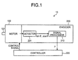
- FIG. 1 is a schematic diagram to explain the motor system according to the embodiment of the present invention.
- a motor system 10 includes a motor 100, an encoder 200, and a controller 300.
- the motor 100 is an example of a power generation source that does not include the encoder 200.
- the motor 100 includes a rotational shaft 101 on at least one side thereof and outputs rotational power by rotating the rotational shaft 101 around a rotational axis.
- the motor 100 may be a linear motor.
- the motor 100 is not limited to a specific motor and any motors can be applicable that are controlled by the controller 300 on the basis of a detection position P output from the encoder 200.
- the motor 100 is not limited to an electrical motor unit that uses electricity as a power source.
- the motor 100 may be a motor unit that uses another power source, such as a hydraulic motor unit, an air motor unit, or a steam motor unit. A case where the motor 100 is the electrical motor unit is described below for expository convenience.
- the encoder 200 is disposed on a side opposite the rotational shaft 101 of the motor 100 and connected to another rotational shaft (not illustrated) that rotates in conjunction with the rotational shaft 101.
- the encoder 200 detects the detection position P (also referred to as a rotational angle, a position of the motor 100, or the like) of the rotational shaft 101 outputting rotational power by detecting a position of the rotational shaft 101, and outputs the detection position P to the controller 300.
- the encoder 200 may detect at least one of a velocity (also referred to as a rotational velocity, an angular velocity, a velocity of the motor 100, or the like) and an acceleration (also referred to as a rotational acceleration, an angular acceleration, an acceleration of the motor 100, or the like) of the rotational shaft 101 in addition to the detection position P of the motor 100.
- a velocity also referred to as a rotational velocity, an angular velocity, a velocity of the motor 100, or the like
- an acceleration also referred to as a rotational acceleration, an angular acceleration, an acceleration of the motor 100, or the like
- the disposition of the encoder 200 is not limited to a specific position.
- the encoder 200 may be disposed so as to be directly connected to the rotational shaft 101 outputting power, or may be connected to a rotating body such as the rotational shaft 101 through another mechanism such as a speed reducer or a rotational direction converter.
- the controller 300 acquires the detection position P output from the encoder 200.
- the controller 300 controls rotation of the motor 100 on the basis of the detection position P. Accordingly, in the embodiment using the electrical motor unit as the motor 100, the controller 300 controls the rotation of the motor 100 by controlling a current or a voltage applied to the motor 100 on the basis of the detection position P. Furthermore, the controller 300 can control the motor 100 by acquiring an upper control signal from an upper controller (not illustrated) such that a position indicated by the upper control signal and the like are output from the rotational axis of the motor 100. When the motor 100 uses other power sources such as hydraulic, air, and steam, the controller 300 can control the rotation of the motor 100 by controlling a supply of the power sources.
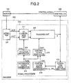
- FIG. 2 is a schematic diagram to explain the encoder 200 according to the embodiment.
- the encoder 200 includes mainly a detector 201 and a signal processor 210.
- the detector 201 outputs an analog sine wave signal and an analog cosine wave signal (examples of a periodic analog signal) in accordance with the position of the motor 100.
- Detectors that employ various detection principles such as optical, magnetic, mechanical, resolver, and hybrid detectors and that are capable of outputting the analog sine wave signal and the analog cosine wave signal in accordance with the position of the motor 100 can be used as the detector 201.
- the signal processor 210 converts the analog sine wave signal and the analog cosine wave signal detected by the detector 201 into the detection position P of the motor 100 at an arithmetic period Tc (also referred to as a detection period) of the detection position P of the motor 100.
- the signal processor 210 includes an AD conversion unit 211, a reference clock generator 212, a control clock generator 213, an AD clock generator 214, an operation state identifier 215, a control clock period determiner 216, and a tracking unit 220.
- the control clock generator 213 and the control clock period determiner 216 are examples of an arithmetic period determiner. Their structures are sequentially described below.
- the reference clock generator 212 generates a reference clock signal CLK0 used as a reference for a control clock signal CLK1 and an AD clock signal CLK2.
- the reference clock generator 212 outputs the reference clock signal CLK0 at a reference period T0.
- the reference period T0 is set shorter than other periods because the reference period T0 is used as a reference for the other periods (the arithmetic period Tc and a conversion period Tad).
- the control clock generator 213 counts the reference clock signal CLK0, generates the control clock signal CLK1 when the count value reaches a predetermined count threshold Cnt1, and resets the count value to zero (0).
- the period at which the control clock signal CLK1 is generated is also referred to as the arithmetic period Tc herein.
- the AD clock generator 214 counts the reference clock signal CLK0, generates the AD clock signal CLK2 when the count value reaches a predetermined count threshold Cnt2, and resets the count value to zero (0).
- the period at which the AD clock signal CLK2 is generated is also referred to as the conversion period Tad herein.
- the AD conversion unit 211 converts the analog sine wave signal and the analog cosine wave signal output from the detector 201 into digital signals at a timing when receiving the AD clock signal CLK2, i.e., for each conversion period Tad.
- the conversion timing for example, whether a case where the reference clock is changed from a Lo level to a Hi level or a case where the reference clock is changed from the Hi level to the Lo level is used, is determined by an AD converter used in the AD conversion unit 211.
- the tracking unit 220 performs closed loop PI control with a proportional gain Kp and an integral gain Ki on input from the AD conversion unit 211, and outputs the detection position P.
- the tracking unit 220 performs the arithmetic processing of the detection position P by the PI control at the timing when the control clock signal CLK1 generated from the control clock generator 213 is changed.
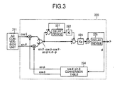
- FIG. 3 is a schematic diagram to explain position arithmetic processing by the tracking technique of the embodiment.
- the tracking unit 220 includes delay devices 221 and 225, an integral gain multiplier 222, a proportional gain multiplier 223, and a cos ⁇ -sin ⁇ conversion table 224.
- the delay device 221 and the integral gain multiplier 222 perform integral arithmetic operation on the value of ⁇ - ⁇ and the proportional gain multiplier 223 multiplies the value of ⁇ - ⁇ by the proportional gain.
- the tracking unit 220 performs the PI control by adding the value of integral and the proportional gain multiplication value.
- the tracking unit 220 calculates ⁇ by adding an output value by the PI control to ⁇ at the last arithmetic period Tc by the delay device 225 and outputs the value of calculated ⁇ to the operation state identifier 215 and the controller 300 as the detection position P.
- control method may be P control, I control, or PID control.
- the operation state identifier 215 calculates a velocity V of the motor 100 on the basis of a difference value of time-series data of the detection position P.
- the operation state identifier 215 calculates an acceleration a of the motor 100 on the basis of a difference value of the velocity V in time series.
- the operation state identifier 215 calculates a jerk j of the motor 100 on the basis of a difference value of the acceleration a in time series.
- the velocity V, the acceleration a, and the jerk j of the motor 100 represent an operation state of the motor 100 at the time when the detection is performed by the detector 201.
- the operation state identifier 215 identifies the operation state of the motor 100 by calculating the acceleration a and the jerk j in this way.
- the operation state is identified by the acceleration a and the jerk j.
- the operation state may not include the jerk j or may include the velocity V if at least the operation state includes the acceleration a.
- the acceleration a may vary due to detection errors and the like. Thus, the inclusion of the jerk j in the operation state enables a more accurate operation state to be identified.
- the control clock period determiner 216 determines the timing when the control clock generator 213 generates the control clock signal CLK1 in accordance with the operation state identified by the operation state identifier 215, i.e., the count threshold Cnt1 of the reference clock signal CLK0, which serves to represent the arithmetic period Tc. As a result, the control clock generator 213 outputs the control clock signal CLK1 to cause the tracking unit 220 to calculate the detection position P each time the count value of the reference clock signal CLK0 reaches the count threshold Cnt1 determined by the control clock period determiner 216.
- the arithmetic period Tc at which the tracking unit 220 calculates the detection position P by the tracking technique is determined by the control clock period determiner 216 and the control clock generator 213 (examples of the arithmetic period determiner).
- the control clock period determiner 216 determines the periods of the control clock signal CLK1 and the AD conversion clock signal CLK2 in accordance with the operation state. Specifically, in static operation and constant velocity operation, the control clock period determiner 216 sets the control clock signal CLK1 and the AD clock signal CLK2 to have the same period by setting the counter threshold Cnt1 and the counter threshold Cnt2 to the same value. In acceleration operation, the control clock period determiner 216 sets the control clock signal CLK1 to have a shorter period than that of the AD clock signal CLK2 by setting the counter threshold Cnt1 to a smaller value than the counter threshold Cnt2.
- FIG. 4 is a graph illustrating a relationship between the detection position P detected by the encoder 200 and an actual position Q when the position arithmetic processing by the tracking technique is performed once at a period of performing the AD conversion.
- FIG. 5 is a graph illustrating a relationship between the detection position P detected by the encoder 200 and the actual position Q when the position arithmetic processing by the tracking technique is performed a plurality of times at the period of performing the AD conversion.
- FIG. 6 is a graph illustrating a relationship between the detection position P detected by the encoder 200 and the actual position Q in the embodiment.
- FIG. 4 illustrates a position detection result when the motor 100 proceeds from the static operation to the constant velocity operation through the acceleration operation.
- the detection position P in the position detection method in which the processing by the tracking technique is performed once at the timing of the AD conversion, i.e., the position detection method in which the conversion period Tad and the arithmetic period Tc are equal to each other, the detection position P can be detected without the difference from the actual position Q in the constant velocity operation including the static operation, but in the acceleration operation, the detection position P delayed from the actual position Q is output due to characteristics of the processing by the tracking technique.
- the tracking unit 220 performs the arithmetic operation faster than the period of the AD conversion such that the detection position P converges to the actual position Q of the motor 100 (conversion period Tad » arithmetic period Tc). Meanwhile, the arithmetic period Tc at which the control clock signal CLK1 is output is set shorter than the conversion period Tad at which the AD conversion clock signal CLK2 is output. In the embodiment, this adjustment is achieved by the control clock period determiner 216 setting the count threshold Cnt1 of the reference clock signal CLK0 in the control clock generator 213 to be a smaller value than the count threshold Cnt2 of the reference clock signal CLK0 in the AD clock generator 214.
- FIG. 5 illustrates the position detection in this state. As illustrated in FIG. 5 , in the position detection from the static operation to the acceleration operation, the value converges well and the delay is reduced by the arithmetic operation repeated within the conversion period Tad.
- the detected detection position P overshoots the actual position Q, and in some cases, a positional error is further increased than a case where the arithmetic period Tc of the tracking unit 220 and the conversion period Tad of the AD conversion unit 211 are equal to each other. Because the tracking unit 220 performs the arithmetic operation faster than the AD conversion, a value of integral input to the integral gain Ki approximates a value of the static operation. This causes the tracking unit 220 to show a phenomenon like a step response when the next AD conversion value is input to the tracking unit 220, thereby resulting in the overshoot of the detection position P.
- the encoder 200 causes the tracking unit 220 to temporarily stop performing the arithmetic operation faster than the period of the AD conversion by causing the control clock period determiner 216 to adjust the count threshold Cnt1 in accordance with the absolute value of the acceleration a representing the operation state of the motor 100 identified by the operation state identifier 215.
- the control clock period determiner 216 deems that the motor 100 is in the constant velocity operation and sets the control clock signal CLK1 and the AD conversion clock signal CLK2 to have the same period. That is, the control clock period determiner 216 causes the tracking unit 220 to stop performing the arithmetic operation faster than the AD conversion by setting the count threshold Cnt1 of the reference clock signal CLK0 in the control clock generator 213 and the count threshold Cnt2 of the reference clock signal CLK0 in the AD clock generator 214 to the same value.
- the control clock period determiner 216 deems that the motor 100 is in the acceleration operation and sets the control clock signal CLK1 to a smaller value than the AD clock signal CLK2. That is, the control clock period determiner 216 causes the tracking unit 220 to perform the arithmetic operation faster than the AD conversion by setting the count threshold Cnt1 of the reference clock signal CLK0 in the control clock generator 213 to a smaller value than the count threshold Cnt2 of the reference clock signal CLK0 in the AD clock generator 214.
- the change of the count threshold Cnt1 in the control clock generator 213 in accordance with the absolute value of the acceleration a is performed on the basis of a threshold TH as a reference of determination.
- the threshold TH can be arbitrarily set by the control clock period determiner 216.
- a change value of the count threshold Cnt in the control clock generator 213 can also be arbitrarily set by the control clock period determiner 216.
- FIG. 6 illustrates a position detection result in this state.
- the detection position P follows the actual position Q well.
- the change of the count threshold Cnt1 in the control clock generator 213 based on the acceleration a is described herein, the count threshold Cnt can also be changed in accordance with the velocity V or the jerk j.
- the motor system 10, the encoder 200 included in the motor system 10, and the signal information processor 210 (the motor system 10 and the like) included in the encoder 200 have been described as above.
- the encoder 200 can reduce a position difference from the actual position Q of the motor 100 due to the delay or the error by causing the tracking unit 220 to perform the arithmetic operation faster than the period of the AD conversion in the acceleration operation such that the detection position P converges to the actual position Q of the motor 100.
- the arithmetic period of the tracking unit 220 can be arbitrarily set to the count threshold Cnt1. As a result, the degree of freedom in arithmetic operation is not limited.
- the tracking unit 220 is caused to stop performing the arithmetic operation faster than the period of the AD conversion in accordance with the acceleration a or the jerk j representing the operation state of the motor 100 identified by the operation state identifier 215, thereby reducing the overshoot of the detection position P and the positional error.
- the change of the arithmetic period of the tracking unit 220 according to the value of the acceleration a or the jerk j is performed on the basis of the threshold TH capable of being arbitrarily set. As a result, the degree of freedom in arithmetic operation is not limited.
- the change of the arithmetic period of the tracking unit 220 can be performed by the signal processor 210 alone, thereby requiring no additional parts, enabling production cost to be reduced, and without limiting the degree of freedom in arithmetic operation of the controller 300.
- the signal processor 210 is disposed in the encoder 200, but the signal processor 210 may be individually formed outside the encoder 200 or may be disposed in the controller 300.
- control clock signal CLK1 in the control clock generator 213 serving as a clock input to the tracking unit 220 is changed in accordance with the operation state in the embodiment, the control clock signal CLK1 and the AD clock signal CLK2 may be switched in accordance with the operation state as the clock input to the tracking unit 220.
Landscapes
- Engineering & Computer Science (AREA)
- Signal Processing (AREA)
- Physics & Mathematics (AREA)
- General Physics & Mathematics (AREA)
- Control Of Electric Motors In General (AREA)
- Transmission And Conversion Of Sensor Element Output (AREA)
Abstract
A problem to be solved is to provide a signal processor, an encoder, and a motor system that can reduce a position difference occurring between a detection position calculated by the encoder and an actual position. To solve the problem, the signal processor includes an AD conversion unit that changes a periodic analog signal output from a detector in accordance with a position Q of a motor to a digital signal at a predetermined conversion period Tad, a tracking unit that calculates a position P of the motor at an arithmetic period Tc on the basis of the digital signal that is converted and output at the conversion period Tad by the AD conversion unit, an operation state identifier that identifies an operation state of the motor on the basis of the position P of the motor calculated by the tracking unit, and an arithmetic period determiner (213), (216) that changes the arithmetic period Tc of the tracking unit in accordance with the operation state of the motor identified by the operation state identifier such that the position P of the motor calculated by the tracking unit follows the actual position Q of the motor.
Description
- The present invention relates to a signal processor, an encoder, and a motor system.
- Encoders are used as means for detecting positions of servo motors, for example. An example of the encoders primarily includes a detector and a signal processor.
- The detector outputs an analog sine wave signal and an analog cosine wave signal in accordance with a position (a rotational angle and the like) of the motor. The signal processor converts the analog sine wave signal and the analog cosine wave signal output from the detector into digital signals using AD conversion and obtains the position of the motor. The signal processor uses a tracking technique as a technique to calculate the position of the motor. In the position calculation method by the tracking technique, the position of the motor is obtained by performing processing by the tracking technique once at AD conversion timing when the analog sine wave signal and the analog cosine wave signal from the detector are converted into the digital signals like an encoder as described in Patent Literature 1.
- Patent Literature 1: Japanese Patent Application Laid-open No.
H4-328410 FIG. 1 ) - In the encoder, however, the processing by the tracking technique by a signal processor does not follow an actual position of the motor when the position of the motor is rapidly changed, thereby causing a delay (a positional difference).
- In view of the above-described problem, the present invention is made and aims to provide a signal processor, an encoder, and a motor system that can reduce a positional difference occurring between a detection position calculated by the encoder and the actual position.
- A signal processor according to an embodiment includes an AD conversion unit that converts a periodic analog signal output from a detector in accordance with a position of a motor into a digital signal at a predetermined conversion period; a tracking unit that calculates the position of the motor at an arithmetic period on the basis of the digital signal that is converted and output at the conversion period by the AD conversion unit; an operation state identifier that identifies an operation state of the motor on the basis of the position of the motor calculated by the tracking unit; and an arithmetic period determiner that changes the arithmetic period of the tracking unit in accordance with the operation state of the motor identified by the operation state identifier such that the position of the motor calculated by the tracking unit follows an actual position of the motor.
- The signal processor according to claim 1, wherein the arithmetic period determiner determines the arithmetic period to be a period equal to or less than the conversion period at which the AD conversion unit outputs the digital signal.
- The signal processor according to
claim 2, wherein the arithmetic period determiner determines the arithmetic period to be a shorter period than the conversion period when the operation state of the motor identified by the operation state identifier represents an acceleration or a deceleration equal to or more than a predetermined degree, and determines the arithmetic period to be a period equal to the conversion period when the operation state of the motor identified by the operation state identifier represents constant velocity operation. - An encoder, comprising: a detector that detects an analog signal periodically changing in accordance with a position of a motor; an AD conversion unit that converts the analog signal detected by the detector into a digital signal at a predetermined conversion period; a tracking unit that calculates the position of the motor at an arithmetic period on the basis of the digital signal that is converted and output at the conversion period by the AD conversion unit; an operation state identifier that identifies an operation state of the motor on the basis of the position of the motor calculated by the tracking unit; and an arithmetic period determiner that changes the arithmetic period of the tracking unit in accordance with the operation state of the motor identified by the operation state identifier such that the position of the motor calculated by the tracking unit follows an actual position of the motor.
- A motor system, comprising: a motor; an encoder that detects a position of the motor; and a controller that controls the motor on the basis of the position of the motor detected by the encoder, wherein the encoder includes: a detector that detects an analog signal periodically changing in accordance with the position of the motor; an AD conversion unit that converts the analog signal detected by the detector into a digital signal at a predetermined conversion period; a tracking unit that calculates the position of the motor at an arithmetic period on the basis of the digital signal that is converted and output at the conversion period by the AD conversion unit; an operation state identifier that identifies an operation state of the motor on the basis of the position of the motor calculated by the tracking unit; and an arithmetic period determiner that changes the arithmetic period of the tracking unit in accordance with the operation state of the motor identified by the operation state identifier such that the position of the motor calculated by the tracking unit follows an actual position of the motor.
- As described above, according to the present invention, the positional difference occurring between the detection position calculated by the encoder and the actual position can be reduced.
-
-
FIG. 1 is a schematic diagram to explain a motor system according to an embodiment of the present invention. -
FIG. 2 is a schematic diagram to explain an encoder according to the embodiment. -
FIG. 3 is a schematic diagram to explain position arithmetic processing by a tracking technique of the embodiment. -
FIG. 4 is a graph illustrating a relationship between a detection position P detected by the encoder and an actual position Q when the position arithmetic processing by the tracking technique is performed once at a period of performing AD conversion. -
FIG. 5 is a graph illustrating a relationship between the detection position P detected by the encoder and the actual position Q when the position arithmetic processing by the tracking technique is performed a plurality of times at the period of performing the AD conversion. -
FIG. 6 is a graph illustrating a relationship between the detection position P detected by the encoder and the actual position Q in the embodiment. - An embodiment of the present invention is described in detail below with reference to the accompanying drawings. In the present description and the drawings, components having substantially the same function are basically labeled with the same numerals and the duplicated explanations thereof are omitted.
- First, with reference to
FIG. 1 , a structure of a motor system according to an embodiment of the present invention is described.FIG. 1 is a schematic diagram to explain the motor system according to the embodiment of the present invention. - As illustrated in
FIG. 1 , amotor system 10 according to the embodiment includes amotor 100, anencoder 200, and acontroller 300. - The
motor 100 is an example of a power generation source that does not include theencoder 200. Themotor 100 includes arotational shaft 101 on at least one side thereof and outputs rotational power by rotating therotational shaft 101 around a rotational axis. Themotor 100 may be a linear motor. - The
motor 100 is not limited to a specific motor and any motors can be applicable that are controlled by thecontroller 300 on the basis of a detection position P output from theencoder 200. In addition, themotor 100 is not limited to an electrical motor unit that uses electricity as a power source. For example, themotor 100 may be a motor unit that uses another power source, such as a hydraulic motor unit, an air motor unit, or a steam motor unit. A case where themotor 100 is the electrical motor unit is described below for expository convenience. - The
encoder 200 is disposed on a side opposite therotational shaft 101 of themotor 100 and connected to another rotational shaft (not illustrated) that rotates in conjunction with therotational shaft 101. Theencoder 200 detects the detection position P (also referred to as a rotational angle, a position of themotor 100, or the like) of therotational shaft 101 outputting rotational power by detecting a position of therotational shaft 101, and outputs the detection position P to thecontroller 300. - The
encoder 200 may detect at least one of a velocity (also referred to as a rotational velocity, an angular velocity, a velocity of themotor 100, or the like) and an acceleration (also referred to as a rotational acceleration, an angular acceleration, an acceleration of themotor 100, or the like) of therotational shaft 101 in addition to the detection position P of themotor 100. In this case, the velocity and the acceleration of themotor 100 can be detected by processing such as differentiation of the detection position P with respect to time once or twice. The following description is made assuming that physical quantity detected by theencoder 200 is the detection position P for expository convenience. - The disposition of the
encoder 200 is not limited to a specific position. For example, theencoder 200 may be disposed so as to be directly connected to therotational shaft 101 outputting power, or may be connected to a rotating body such as therotational shaft 101 through another mechanism such as a speed reducer or a rotational direction converter. - The
controller 300 acquires the detection position P output from theencoder 200. Thecontroller 300 controls rotation of themotor 100 on the basis of the detection position P. Accordingly, in the embodiment using the electrical motor unit as themotor 100, thecontroller 300 controls the rotation of themotor 100 by controlling a current or a voltage applied to themotor 100 on the basis of the detection position P. Furthermore, thecontroller 300 can control themotor 100 by acquiring an upper control signal from an upper controller (not illustrated) such that a position indicated by the upper control signal and the like are output from the rotational axis of themotor 100. When themotor 100 uses other power sources such as hydraulic, air, and steam, thecontroller 300 can control the rotation of themotor 100 by controlling a supply of the power sources. - Next, with reference to
FIG. 2 , a structure of theencoder 200 according to the embodiment of the present invention is described.FIG. 2 is a schematic diagram to explain theencoder 200 according to the embodiment. - As illustrated in
FIG. 2 , theencoder 200 according to the embodiment includes mainly adetector 201 and asignal processor 210. - The
detector 201 outputs an analog sine wave signal and an analog cosine wave signal (examples of a periodic analog signal) in accordance with the position of themotor 100. Detectors that employ various detection principles such as optical, magnetic, mechanical, resolver, and hybrid detectors and that are capable of outputting the analog sine wave signal and the analog cosine wave signal in accordance with the position of themotor 100 can be used as thedetector 201. - The
signal processor 210 converts the analog sine wave signal and the analog cosine wave signal detected by thedetector 201 into the detection position P of themotor 100 at an arithmetic period Tc (also referred to as a detection period) of the detection position P of themotor 100. - As illustrated in
FIG. 2 in further detail, thesignal processor 210 includes anAD conversion unit 211, areference clock generator 212, acontrol clock generator 213, anAD clock generator 214, anoperation state identifier 215, a control clock period determiner 216, and atracking unit 220. Thecontrol clock generator 213 and the control clock period determiner 216 are examples of an arithmetic period determiner. Their structures are sequentially described below. - The
reference clock generator 212 generates a reference clock signal CLK0 used as a reference for a control clock signal CLK1 and an AD clock signal CLK2. Thereference clock generator 212 outputs the reference clock signal CLK0 at a reference period T0. The reference period T0 is set shorter than other periods because the reference period T0 is used as a reference for the other periods (the arithmetic period Tc and a conversion period Tad). - The
control clock generator 213 counts the reference clock signal CLK0, generates the control clock signal CLK1 when the count value reaches a predetermined count threshold Cnt1, and resets the count value to zero (0). The period at which the control clock signal CLK1 is generated is also referred to as the arithmetic period Tc herein. - The
AD clock generator 214 counts the reference clock signal CLK0, generates the AD clock signal CLK2 when the count value reaches a predetermined count threshold Cnt2, and resets the count value to zero (0). The period at which the AD clock signal CLK2 is generated is also referred to as the conversion period Tad herein. - The
AD conversion unit 211 converts the analog sine wave signal and the analog cosine wave signal output from thedetector 201 into digital signals at a timing when receiving the AD clock signal CLK2, i.e., for each conversion period Tad. The conversion timing, for example, whether a case where the reference clock is changed from a Lo level to a Hi level or a case where the reference clock is changed from the Hi level to the Lo level is used, is determined by an AD converter used in theAD conversion unit 211. - The
tracking unit 220 performs closed loop PI control with a proportional gain Kp and an integral gain Ki on input from theAD conversion unit 211, and outputs the detection position P. Thetracking unit 220 performs the arithmetic processing of the detection position P by the PI control at the timing when the control clock signal CLK1 generated from thecontrol clock generator 213 is changed. - Operation of the
tracking unit 220 is described with reference toFIG. 3. FIG. 3 is a schematic diagram to explain position arithmetic processing by the tracking technique of the embodiment. - As illustrated in
FIG. 3 , thetracking unit 220 includesdelay devices integral gain multiplier 222, aproportional gain multiplier 223, and a cosφ-sinφ conversion table 224. - The
tracking unit 220, which has the structure illustrated inFIG. 3 , calculates the detection position P and the like in the following manner. That is, thetracking unit 220 multiplies cosθ and sinθ from theAD conversion unit 211 by cosφ and sinφ, which are converted by the cosφ-sinφ conversion table 224 using φ at the last arithmetic period Tc, as indicated inFIG. 3 , and calculates sinθ•cosφ - cosθ•sinφ = sin(8 - φ) ≅ θ - φ. Then, thetracking unit 220 performs arithmetic operation by the PI control such that a value of θ - φ approximates zero. Specifically, thedelay device 221 and theintegral gain multiplier 222 perform integral arithmetic operation on the value of θ - φ and theproportional gain multiplier 223 multiplies the value of θ - φ by the proportional gain. In this way, thetracking unit 220 performs the PI control by adding the value of integral and the proportional gain multiplication value. In addition, thetracking unit 220 calculates φ by adding an output value by the PI control to φ at the last arithmetic period Tc by thedelay device 225 and outputs the value of calculated φ to theoperation state identifier 215 and thecontroller 300 as the detection position P. - Although the tracking processing by the PI control is described herein, the control method may be P control, I control, or PID control.
- The
operation state identifier 215 calculates a velocity V of themotor 100 on the basis of a difference value of time-series data of the detection position P. Theoperation state identifier 215 calculates an acceleration a of themotor 100 on the basis of a difference value of the velocity V in time series. In addition, theoperation state identifier 215 calculates a jerk j of themotor 100 on the basis of a difference value of the acceleration a in time series. - The velocity V, the acceleration a, and the jerk j of the
motor 100 represent an operation state of themotor 100 at the time when the detection is performed by thedetector 201. Theoperation state identifier 215 identifies the operation state of themotor 100 by calculating the acceleration a and the jerk j in this way. Herein, it is described that the operation state is identified by the acceleration a and the jerk j. The operation state, however, may not include the jerk j or may include the velocity V if at least the operation state includes the acceleration a. The acceleration a may vary due to detection errors and the like. Thus, the inclusion of the jerk j in the operation state enables a more accurate operation state to be identified. - The control
clock period determiner 216 determines the timing when thecontrol clock generator 213 generates the control clock signal CLK1 in accordance with the operation state identified by theoperation state identifier 215, i.e., the count threshold Cnt1 of the reference clock signal CLK0, which serves to represent the arithmetic period Tc. As a result, thecontrol clock generator 213 outputs the control clock signal CLK1 to cause thetracking unit 220 to calculate the detection position P each time the count value of the reference clock signal CLK0 reaches the count threshold Cnt1 determined by the controlclock period determiner 216. That is, the arithmetic period Tc at which thetracking unit 220 calculates the detection position P by the tracking technique, is determined by the controlclock period determiner 216 and the control clock generator 213 (examples of the arithmetic period determiner). - The control
clock period determiner 216 determines the periods of the control clock signal CLK1 and the AD conversion clock signal CLK2 in accordance with the operation state. Specifically, in static operation and constant velocity operation, the controlclock period determiner 216 sets the control clock signal CLK1 and the AD clock signal CLK2 to have the same period by setting the counter threshold Cnt1 and the counter threshold Cnt2 to the same value. In acceleration operation, the controlclock period determiner 216 sets the control clock signal CLK1 to have a shorter period than that of the AD clock signal CLK2 by setting the counter threshold Cnt1 to a smaller value than the counter threshold Cnt2. - The structures of the
motor system 10 according to the embodiment and the like are described as above. - Next, an example of the operation of the
motor system 10 and the like is described by exemplifying processing examples in each structure in greater detail. - With reference to
FIGS. 4 to 6 , an example of, particularly, output operation of the detection position P performed by theencoder 200 in themotor system 10 according to the embodiment and the like is described. -
FIG. 4 is a graph illustrating a relationship between the detection position P detected by theencoder 200 and an actual position Q when the position arithmetic processing by the tracking technique is performed once at a period of performing the AD conversion.FIG. 5 is a graph illustrating a relationship between the detection position P detected by theencoder 200 and the actual position Q when the position arithmetic processing by the tracking technique is performed a plurality of times at the period of performing the AD conversion.FIG. 6 is a graph illustrating a relationship between the detection position P detected by theencoder 200 and the actual position Q in the embodiment. -
FIG. 4 illustrates a position detection result when themotor 100 proceeds from the static operation to the constant velocity operation through the acceleration operation. As illustrated inFIG. 4 , in the position detection method in which the processing by the tracking technique is performed once at the timing of the AD conversion, i.e., the position detection method in which the conversion period Tad and the arithmetic period Tc are equal to each other, the detection position P can be detected without the difference from the actual position Q in the constant velocity operation including the static operation, but in the acceleration operation, the detection position P delayed from the actual position Q is output due to characteristics of the processing by the tracking technique. - To reduce the delay, the
tracking unit 220 performs the arithmetic operation faster than the period of the AD conversion such that the detection position P converges to the actual position Q of the motor 100 (conversion period Tad » arithmetic period Tc). Meanwhile, the arithmetic period Tc at which the control clock signal CLK1 is output is set shorter than the conversion period Tad at which the AD conversion clock signal CLK2 is output. In the embodiment, this adjustment is achieved by the controlclock period determiner 216 setting the count threshold Cnt1 of the reference clock signal CLK0 in thecontrol clock generator 213 to be a smaller value than the count threshold Cnt2 of the reference clock signal CLK0 in theAD clock generator 214.FIG. 5 illustrates the position detection in this state. As illustrated inFIG. 5 , in the position detection from the static operation to the acceleration operation, the value converges well and the delay is reduced by the arithmetic operation repeated within the conversion period Tad. - However, in the constant velocity operation, the detected detection position P overshoots the actual position Q, and in some cases, a positional error is further increased than a case where the arithmetic period Tc of the
tracking unit 220 and the conversion period Tad of theAD conversion unit 211 are equal to each other. Because thetracking unit 220 performs the arithmetic operation faster than the AD conversion, a value of integral input to the integral gain Ki approximates a value of the static operation. This causes thetracking unit 220 to show a phenomenon like a step response when the next AD conversion value is input to thetracking unit 220, thereby resulting in the overshoot of the detection position P. - To avoid the phenomenon, the
encoder 200 according to the embodiment causes thetracking unit 220 to temporarily stop performing the arithmetic operation faster than the period of the AD conversion by causing the controlclock period determiner 216 to adjust the count threshold Cnt1 in accordance with the absolute value of the acceleration a representing the operation state of themotor 100 identified by theoperation state identifier 215. - For example, when the absolute value of the acceleration a is close to zero, the control
clock period determiner 216 deems that themotor 100 is in the constant velocity operation and sets the control clock signal CLK1 and the AD conversion clock signal CLK2 to have the same period. That is, the controlclock period determiner 216 causes thetracking unit 220 to stop performing the arithmetic operation faster than the AD conversion by setting the count threshold Cnt1 of the reference clock signal CLK0 in thecontrol clock generator 213 and the count threshold Cnt2 of the reference clock signal CLK0 in theAD clock generator 214 to the same value. - On the other hand, for example, when the absolute value of the acceleration a is somewhat larger than zero, the control
clock period determiner 216 deems that themotor 100 is in the acceleration operation and sets the control clock signal CLK1 to a smaller value than the AD clock signal CLK2. That is, the controlclock period determiner 216 causes thetracking unit 220 to perform the arithmetic operation faster than the AD conversion by setting the count threshold Cnt1 of the reference clock signal CLK0 in thecontrol clock generator 213 to a smaller value than the count threshold Cnt2 of the reference clock signal CLK0 in theAD clock generator 214. - The change of the count threshold Cnt1 in the
control clock generator 213 in accordance with the absolute value of the acceleration a is performed on the basis of a threshold TH as a reference of determination. The threshold TH can be arbitrarily set by the controlclock period determiner 216. A change value of the count threshold Cnt in thecontrol clock generator 213 can also be arbitrarily set by the controlclock period determiner 216. -
FIG. 6 illustrates a position detection result in this state. As illustrated inFIG. 6 , while an overshoot remains in the switching from the acceleration operation to the constant velocity operation, in the succeeding constant velocity operation, the detection position P follows the actual position Q well. Although the change of the count threshold Cnt1 in thecontrol clock generator 213 based on the acceleration a is described herein, the count threshold Cnt can also be changed in accordance with the velocity V or the jerk j. - The
motor system 10, theencoder 200 included in themotor system 10, and the signal information processor 210 (themotor system 10 and the like) included in theencoder 200 have been described as above. - The
encoder 200 according to the embodiment can reduce a position difference from the actual position Q of themotor 100 due to the delay or the error by causing thetracking unit 220 to perform the arithmetic operation faster than the period of the AD conversion in the acceleration operation such that the detection position P converges to the actual position Q of themotor 100. At this time, the arithmetic period of thetracking unit 220 can be arbitrarily set to the count threshold Cnt1. As a result, the degree of freedom in arithmetic operation is not limited. - In the constant velocity operation, the
tracking unit 220 is caused to stop performing the arithmetic operation faster than the period of the AD conversion in accordance with the acceleration a or the jerk j representing the operation state of themotor 100 identified by theoperation state identifier 215, thereby reducing the overshoot of the detection position P and the positional error. The change of the arithmetic period of thetracking unit 220 according to the value of the acceleration a or the jerk j is performed on the basis of the threshold TH capable of being arbitrarily set. As a result, the degree of freedom in arithmetic operation is not limited. - In addition, the change of the arithmetic period of the
tracking unit 220 can be performed by thesignal processor 210 alone, thereby requiring no additional parts, enabling production cost to be reduced, and without limiting the degree of freedom in arithmetic operation of thecontroller 300. - The embodiment of the present invention has been described in detail with reference to the accompanying drawings as above. However, it is needless to say that the present invention is not limited to the examples of the embodiment. It is apparent that those who have normal knowledge in the technical field to which the present invention belongs can make various changes and modifications within the scope of technical idea described in the claims. Therefore, the techniques after the changes and modifications deservingly belong to the technical scope of the present invention.
- For example, in the embodiment, the
signal processor 210 is disposed in theencoder 200, but thesignal processor 210 may be individually formed outside theencoder 200 or may be disposed in thecontroller 300. - Although the control clock signal CLK1 in the
control clock generator 213 serving as a clock input to thetracking unit 220 is changed in accordance with the operation state in the embodiment, the control clock signal CLK1 and the AD clock signal CLK2 may be switched in accordance with the operation state as the clock input to thetracking unit 220. -
- 10
- motor system
- 100
- motor
- 101
- rotational shaft
- 200
- encoder
- 201
- detector
- 210
- signal processor
- 211
- AD conversion unit
- 212
- reference clock generator
- 213
- control clock generator
- 214
- AD clock generator
- 215
- operation state identifier
- 216
- control clock period determiner
- 220
- tracking unit
- 221
- delay device
- 222
- integral gain multiplier
- 223
- proportional gain multiplier
- 224
- cosφ-sinφ conversion table
- 225
- delay device
- 300
- controller
Claims (5)
- A signal processor, comprising:an AD conversion unit that converts a periodic analog signal output from a detector in accordance with a position of a motor into a digital signal at a predetermined conversion period;a tracking unit that calculates the position of the motor at an arithmetic period on the basis of the digital signal that is converted and output at the conversion period by the AD conversion unit;an operation state identifier that identifies an operation state of the motor on the basis of the position of the motor calculated by the tracking unit; andan arithmetic period determiner that changes the arithmetic period of the tracking unit in accordance with the operation state of the motor identified by the operation state identifier such that the position of the motor calculated by the tracking unit follows an actual position of the motor.
- The signal processor according to claim 1, wherein the arithmetic period determiner determines the arithmetic period to be a period equal to or less than the conversion period at which the AD conversion unit outputs the digital signal.
- The signal processor according to claim 2, wherein the arithmetic period determiner determines the arithmetic period to be a shorter period than the conversion period when the operation state of the motor identified by the operation state identifier represents an acceleration or a deceleration equal to or more than a predetermined degree, and determines the arithmetic period to be a period equal to the conversion period when the operation state of the motor identified by the operation state identifier represents constant velocity operation.
- An encoder, comprising:a detector that detects an analog signal periodically changing in accordance with a position of a motor;an AD conversion unit that converts the analog signal detected by the detector into a digital signal at a predetermined conversion period;a tracking unit that calculates the position of the motor at an arithmetic period on the basis of the digital signal that is converted and output at the conversion period by the AD conversion unit;an operation state identifier that identifies an operation state of the motor on the basis of the position of the motor calculated by the tracking unit; andan arithmetic period determiner that changes the arithmetic period of the tracking unit in accordance with the operation state of the motor identified by the operation state identifier such that the position of the motor calculated by the tracking unit follows an actual position of the motor.
- A motor system, comprising:a motor;an encoder that detects a position of the motor; anda controller that controls the motor on the basis of the position of the motor detected by the encoder, whereinthe encoder includes:a detector that detects an analog signal periodically changing in accordance with the position of the motor;an AD conversion unit that converts the analog signal detected by the detector into a digital signal at a predetermined conversion period;a tracking unit that calculates the position of the motor at an arithmetic period on the basis of the digital signal that is converted and output at the conversion period by the AD conversion unit;an operation state identifier that identifies an operation state of the motor on the basis of the position of the motor calculated by the tracking unit; andan arithmetic period determiner that changes the arithmetic period of the tracking unit in accordance with the operation state of the motor identified by the operation state identifier such that the position of the motor calculated by the tracking unit follows an actual position of the motor.
Applications Claiming Priority (2)
| Application Number | Priority Date | Filing Date | Title |
|---|---|---|---|
| JP2010085799 | 2010-04-02 | ||
| PCT/JP2011/051215 WO2011125360A1 (en) | 2010-04-02 | 2011-01-24 | Signal processor, encoder, and motor system |
Publications (2)
| Publication Number | Publication Date |
|---|---|
| EP2554951A1 true EP2554951A1 (en) | 2013-02-06 |
| EP2554951A4 EP2554951A4 (en) | 2014-09-24 |
Family
ID=44762327
Family Applications (1)
| Application Number | Title | Priority Date | Filing Date |
|---|---|---|---|
| EP11765262.8A Withdrawn EP2554951A4 (en) | 2010-04-02 | 2011-01-24 | SIGNAL, ENCODER, AND ENGINE PROCESSOR SYSTEM |
Country Status (5)
| Country | Link |
|---|---|
| US (1) | US8884572B2 (en) |
| EP (1) | EP2554951A4 (en) |
| JP (1) | JP5545360B2 (en) |
| CN (1) | CN102822637B (en) |
| WO (1) | WO2011125360A1 (en) |
Cited By (2)
| Publication number | Priority date | Publication date | Assignee | Title |
|---|---|---|---|---|
| EP2787326A1 (en) * | 2013-04-03 | 2014-10-08 | Canon Kabushiki Kaisha | Encoder and method of outputting measurement value of position or angle |
| WO2014083338A3 (en) * | 2012-11-30 | 2015-05-14 | Trw Limited | Improvements in motor controllers |
Families Citing this family (6)
| Publication number | Priority date | Publication date | Assignee | Title |
|---|---|---|---|---|
| KR101540176B1 (en) * | 2014-03-13 | 2015-07-28 | 엘에스산전 주식회사 | Apparatus for detecting speed of moror |
| JP2016123237A (en) * | 2014-12-25 | 2016-07-07 | 株式会社ジェイテクト | Motor unit |
| JP6235505B2 (en) * | 2015-02-27 | 2017-11-22 | ファナック株式会社 | Encoder signal processing apparatus having automatic adjustment function |
| DE112016005619T5 (en) * | 2015-12-08 | 2018-10-04 | Asahi Kasei Microdevices Corporation | Rotation information detection device, angle detection circuit, rotation information detection method and rotation information detection program |
| WO2020148764A2 (en) * | 2019-01-17 | 2020-07-23 | Shahar Dan Yehoshoa | Pipettor calibration system devices and methods therof |
| JP6607423B1 (en) * | 2019-03-01 | 2019-11-20 | 株式会社安川電機 | Encoder, servo motor, servo system |
Family Cites Families (14)
| Publication number | Priority date | Publication date | Assignee | Title |
|---|---|---|---|---|
| US5254919A (en) * | 1991-03-22 | 1993-10-19 | Eastman Kodak Company | Encoder system using linear array sensor for high resolution |
| JPH04328410A (en) | 1991-04-26 | 1992-11-17 | Yaskawa Electric Corp | Position detecting method |
| US5998783A (en) * | 1994-06-01 | 1999-12-07 | Stridsberg Innovation Ab | Heat protected position transducer in an electric motor |
| US5642461A (en) * | 1994-11-14 | 1997-06-24 | Seagate Technology, Inc. | Economical wide range speed control system |
| JP3367260B2 (en) * | 1995-03-24 | 2003-01-14 | 三菱電機株式会社 | Encoder device and servo motor control device |
| JPH08272420A (en) * | 1995-03-29 | 1996-10-18 | Mitsubishi Electric Corp | Positioning device |
| JP2953502B2 (en) * | 1996-06-28 | 1999-09-27 | 日本精機株式会社 | Driving device for stepping motor type instrument |
| US6227644B1 (en) * | 1998-05-04 | 2001-05-08 | Hewlett-Packard Company | Inkjet dot imaging sensor for the calibration of inkjet print heads |
| JP3893033B2 (en) * | 2001-06-29 | 2007-03-14 | オークマ株式会社 | Position detection device |
| DE60223898T2 (en) * | 2002-01-30 | 2008-11-27 | Continental Automotive Gmbh | Method and device for determining the rotor position of a motor by feeding a resolver signal derived from the rotor position into a single control system which serves both to trigger and to determine the resolver signal, and to a motorized vehicle equipped with such a device is |
| US7607437B2 (en) * | 2003-08-04 | 2009-10-27 | Cardinal Health 203, Inc. | Compressor control system and method for a portable ventilator |
| US7508154B1 (en) * | 2006-05-15 | 2009-03-24 | Quicksilver Controls, Inc. | Integrated motor and resolver including absolute position capability |
| JP4729002B2 (en) * | 2007-05-29 | 2011-07-20 | 株式会社リコー | Servo control device, method and program, and ink jet recording apparatus |
| JP5076858B2 (en) * | 2007-12-13 | 2012-11-21 | パナソニック株式会社 | Motor control device |
-
2011
- 2011-01-24 JP JP2012509331A patent/JP5545360B2/en not_active Expired - Fee Related
- 2011-01-24 CN CN201180017393.1A patent/CN102822637B/en not_active Expired - Fee Related
- 2011-01-24 EP EP11765262.8A patent/EP2554951A4/en not_active Withdrawn
- 2011-01-24 WO PCT/JP2011/051215 patent/WO2011125360A1/en not_active Ceased
-
2012
- 2012-10-01 US US13/632,159 patent/US8884572B2/en not_active Expired - Fee Related
Cited By (3)
| Publication number | Priority date | Publication date | Assignee | Title |
|---|---|---|---|---|
| WO2014083338A3 (en) * | 2012-11-30 | 2015-05-14 | Trw Limited | Improvements in motor controllers |
| EP2787326A1 (en) * | 2013-04-03 | 2014-10-08 | Canon Kabushiki Kaisha | Encoder and method of outputting measurement value of position or angle |
| US10072950B2 (en) | 2013-04-03 | 2018-09-11 | Canon Kabushiki Kaisha | Encoder and method of outputting measurement value of position or angle |
Also Published As
| Publication number | Publication date |
|---|---|
| US20130026965A1 (en) | 2013-01-31 |
| JP5545360B2 (en) | 2014-07-09 |
| WO2011125360A1 (en) | 2011-10-13 |
| JPWO2011125360A1 (en) | 2013-07-08 |
| CN102822637A (en) | 2012-12-12 |
| CN102822637B (en) | 2015-03-04 |
| US8884572B2 (en) | 2014-11-11 |
| EP2554951A4 (en) | 2014-09-24 |
Similar Documents
| Publication | Publication Date | Title |
|---|---|---|
| US8884572B2 (en) | Signal processor, encoder, and motor system | |
| US10439525B2 (en) | Motor drive device and method for driving motor | |
| US8775117B2 (en) | Encoder, servo unit, and method including calculating position data | |
| US20150295525A1 (en) | Brushless Motors with Linear Hall Sensors | |
| CN202906812U (en) | Motor state signal detection apparatus based on linear Hall sensor | |
| CN105811828B (en) | A kind of Speed of Reaction Wheels control device and method based on linear hall sensor | |
| CN105811824A (en) | Micro/nano-satellite reaction flywheel control method based on linear Hall | |
| CN101888206A (en) | A Permanent Magnet Synchronous Linear Motor Driver | |
| CN202918231U (en) | Sewing machine brushless direct-current motor control system | |
| JP7158891B2 (en) | Motor drive device and motor drive method | |
| JP2019141970A (en) | Arm rotary shaft speed detector of robot | |
| JPH09292264A (en) | Absolute encoder | |
| Long et al. | Design of AC servo motor control system based on XC164CM microcontroller | |
| JP6432037B2 (en) | Resolver angular position detector | |
| Xu et al. | Multiple linear motor control system based on FPGA | |
| Liu et al. | Design of stepper motor position control system based on DSP | |
| US8957620B2 (en) | Motor control apparatus, motor control method, motor system, and computer-readable medium | |
| EP3679645B1 (en) | Method of controlling a brushless dc motor | |
| JP5736968B2 (en) | Encoder device, drive device, and robot system | |
| Tiapkin et al. | Architecture of multi-axis motion controller for precision electric drive | |
| JP2012220476A (en) | Position detector | |
| CN202309597U (en) | Permanent magnet synchronous motor transmission system free of UVW position signal detection | |
| KR20190102718A (en) | Position control system using magnet mover | |
| JP2008008739A (en) | Signal processing system, speed detection system, servomechanism | |
| CN103001556A (en) | DSP (digital signal processor)-based alternating-current servo voltage control system |
Legal Events
| Date | Code | Title | Description |
|---|---|---|---|
| PUAI | Public reference made under article 153(3) epc to a published international application that has entered the european phase |
Free format text: ORIGINAL CODE: 0009012 |
|
| 17P | Request for examination filed |
Effective date: 20121001 |
|
| AK | Designated contracting states |
Kind code of ref document: A1 Designated state(s): AL AT BE BG CH CY CZ DE DK EE ES FI FR GB GR HR HU IE IS IT LI LT LU LV MC MK MT NL NO PL PT RO RS SE SI SK SM TR |
|
| DAX | Request for extension of the european patent (deleted) | ||
| A4 | Supplementary search report drawn up and despatched |
Effective date: 20140825 |
|
| RIC1 | Information provided on ipc code assigned before grant |
Ipc: G01D 5/244 20060101AFI20140819BHEP |
|
| STAA | Information on the status of an ep patent application or granted ep patent |
Free format text: STATUS: THE APPLICATION HAS BEEN WITHDRAWN |
|
| 18W | Application withdrawn |
Effective date: 20160718 |