EP2554874A2 - Journal pin oil supply for gear system - Google Patents
Journal pin oil supply for gear system Download PDFInfo
- Publication number
- EP2554874A2 EP2554874A2 EP12178865A EP12178865A EP2554874A2 EP 2554874 A2 EP2554874 A2 EP 2554874A2 EP 12178865 A EP12178865 A EP 12178865A EP 12178865 A EP12178865 A EP 12178865A EP 2554874 A2 EP2554874 A2 EP 2554874A2
- Authority
- EP
- European Patent Office
- Prior art keywords
- chamber
- journal pin
- section
- recess
- supply passage
- Prior art date
- Legal status (The legal status is an assumption and is not a legal conclusion. Google has not performed a legal analysis and makes no representation as to the accuracy of the status listed.)
- Granted
Links
- 238000004891 communication Methods 0.000 claims abstract description 11
- 239000012530 fluid Substances 0.000 claims abstract description 11
- 230000004323 axial length Effects 0.000 claims description 9
- 238000000034 method Methods 0.000 claims description 5
- 230000008878 coupling Effects 0.000 description 7
- 238000010168 coupling process Methods 0.000 description 7
- 238000005859 coupling reaction Methods 0.000 description 7
- 238000005461 lubrication Methods 0.000 description 3
- 230000006835 compression Effects 0.000 description 1
- 238000007906 compression Methods 0.000 description 1
- 230000003247 decreasing effect Effects 0.000 description 1
- 230000001419 dependent effect Effects 0.000 description 1
- 239000000446 fuel Substances 0.000 description 1
- 230000020169 heat generation Effects 0.000 description 1
- 238000012986 modification Methods 0.000 description 1
- 230000004048 modification Effects 0.000 description 1
- 238000011176 pooling Methods 0.000 description 1
- 238000010008 shearing Methods 0.000 description 1
Images
Classifications
-
- F—MECHANICAL ENGINEERING; LIGHTING; HEATING; WEAPONS; BLASTING
- F16—ENGINEERING ELEMENTS AND UNITS; GENERAL MEASURES FOR PRODUCING AND MAINTAINING EFFECTIVE FUNCTIONING OF MACHINES OR INSTALLATIONS; THERMAL INSULATION IN GENERAL
- F16H—GEARING
- F16H57/00—General details of gearing
- F16H57/04—Features relating to lubrication or cooling or heating
- F16H57/042—Guidance of lubricant
- F16H57/043—Guidance of lubricant within rotary parts, e.g. axial channels or radial openings in shafts
-
- F—MECHANICAL ENGINEERING; LIGHTING; HEATING; WEAPONS; BLASTING
- F02—COMBUSTION ENGINES; HOT-GAS OR COMBUSTION-PRODUCT ENGINE PLANTS
- F02C—GAS-TURBINE PLANTS; AIR INTAKES FOR JET-PROPULSION PLANTS; CONTROLLING FUEL SUPPLY IN AIR-BREATHING JET-PROPULSION PLANTS
- F02C7/00—Features, components parts, details or accessories, not provided for in, or of interest apart form groups F02C1/00 - F02C6/00; Air intakes for jet-propulsion plants
- F02C7/32—Arrangement, mounting, or driving, of auxiliaries
-
- F—MECHANICAL ENGINEERING; LIGHTING; HEATING; WEAPONS; BLASTING
- F16—ENGINEERING ELEMENTS AND UNITS; GENERAL MEASURES FOR PRODUCING AND MAINTAINING EFFECTIVE FUNCTIONING OF MACHINES OR INSTALLATIONS; THERMAL INSULATION IN GENERAL
- F16C—SHAFTS; FLEXIBLE SHAFTS; ELEMENTS OR CRANKSHAFT MECHANISMS; ROTARY BODIES OTHER THAN GEARING ELEMENTS; BEARINGS
- F16C33/00—Parts of bearings; Special methods for making bearings or parts thereof
- F16C33/02—Parts of sliding-contact bearings
-
- F—MECHANICAL ENGINEERING; LIGHTING; HEATING; WEAPONS; BLASTING
- F16—ENGINEERING ELEMENTS AND UNITS; GENERAL MEASURES FOR PRODUCING AND MAINTAINING EFFECTIVE FUNCTIONING OF MACHINES OR INSTALLATIONS; THERMAL INSULATION IN GENERAL
- F16H—GEARING
- F16H57/00—General details of gearing
- F16H57/04—Features relating to lubrication or cooling or heating
- F16H57/0467—Elements of gearings to be lubricated, cooled or heated
- F16H57/0479—Gears or bearings on planet carriers
-
- F—MECHANICAL ENGINEERING; LIGHTING; HEATING; WEAPONS; BLASTING
- F05—INDEXING SCHEMES RELATING TO ENGINES OR PUMPS IN VARIOUS SUBCLASSES OF CLASSES F01-F04
- F05D—INDEXING SCHEME FOR ASPECTS RELATING TO NON-POSITIVE-DISPLACEMENT MACHINES OR ENGINES, GAS-TURBINES OR JET-PROPULSION PLANTS
- F05D2260/00—Function
- F05D2260/40—Transmission of power
- F05D2260/403—Transmission of power through the shape of the drive components
- F05D2260/4031—Transmission of power through the shape of the drive components as in toothed gearing
- F05D2260/40311—Transmission of power through the shape of the drive components as in toothed gearing of the epicyclical, planetary or differential type
-
- F—MECHANICAL ENGINEERING; LIGHTING; HEATING; WEAPONS; BLASTING
- F16—ENGINEERING ELEMENTS AND UNITS; GENERAL MEASURES FOR PRODUCING AND MAINTAINING EFFECTIVE FUNCTIONING OF MACHINES OR INSTALLATIONS; THERMAL INSULATION IN GENERAL
- F16C—SHAFTS; FLEXIBLE SHAFTS; ELEMENTS OR CRANKSHAFT MECHANISMS; ROTARY BODIES OTHER THAN GEARING ELEMENTS; BEARINGS
- F16C2360/00—Engines or pumps
- F16C2360/23—Gas turbine engines
-
- F—MECHANICAL ENGINEERING; LIGHTING; HEATING; WEAPONS; BLASTING
- F16—ENGINEERING ELEMENTS AND UNITS; GENERAL MEASURES FOR PRODUCING AND MAINTAINING EFFECTIVE FUNCTIONING OF MACHINES OR INSTALLATIONS; THERMAL INSULATION IN GENERAL
- F16C—SHAFTS; FLEXIBLE SHAFTS; ELEMENTS OR CRANKSHAFT MECHANISMS; ROTARY BODIES OTHER THAN GEARING ELEMENTS; BEARINGS
- F16C2361/00—Apparatus or articles in engineering in general
- F16C2361/61—Toothed gear systems, e.g. support of pinion shafts
-
- F—MECHANICAL ENGINEERING; LIGHTING; HEATING; WEAPONS; BLASTING
- F16—ENGINEERING ELEMENTS AND UNITS; GENERAL MEASURES FOR PRODUCING AND MAINTAINING EFFECTIVE FUNCTIONING OF MACHINES OR INSTALLATIONS; THERMAL INSULATION IN GENERAL
- F16H—GEARING
- F16H57/00—General details of gearing
- F16H57/08—General details of gearing of gearings with members having orbital motion
- F16H2057/085—Bearings for orbital gears
-
- Y—GENERAL TAGGING OF NEW TECHNOLOGICAL DEVELOPMENTS; GENERAL TAGGING OF CROSS-SECTIONAL TECHNOLOGIES SPANNING OVER SEVERAL SECTIONS OF THE IPC; TECHNICAL SUBJECTS COVERED BY FORMER USPC CROSS-REFERENCE ART COLLECTIONS [XRACs] AND DIGESTS
- Y02—TECHNOLOGIES OR APPLICATIONS FOR MITIGATION OR ADAPTATION AGAINST CLIMATE CHANGE
- Y02T—CLIMATE CHANGE MITIGATION TECHNOLOGIES RELATED TO TRANSPORTATION
- Y02T50/00—Aeronautics or air transport
- Y02T50/60—Efficient propulsion technologies, e.g. for aircraft
-
- Y—GENERAL TAGGING OF NEW TECHNOLOGICAL DEVELOPMENTS; GENERAL TAGGING OF CROSS-SECTIONAL TECHNOLOGIES SPANNING OVER SEVERAL SECTIONS OF THE IPC; TECHNICAL SUBJECTS COVERED BY FORMER USPC CROSS-REFERENCE ART COLLECTIONS [XRACs] AND DIGESTS
- Y10—TECHNICAL SUBJECTS COVERED BY FORMER USPC
- Y10T—TECHNICAL SUBJECTS COVERED BY FORMER US CLASSIFICATION
- Y10T29/00—Metal working
- Y10T29/49—Method of mechanical manufacture
- Y10T29/49462—Gear making
- Y10T29/49464—Assembling of gear into force transmitting device
Definitions
- This disclosure relates to a gear system and, in particular, to journal pins in an epicyclic gear system.
- Turbomachines such as gas turbine engines, typically propel aircraft and include a fan section, a turbine section, a compressor section, and a combustor section. Turbomachines may employ an epicyclic gear system connecting the fan section and the turbine section. Journal pins hold planet (or star) gears between the sun gear and a ring gear. The journal pins connect the planet gears to a gear carrier.
- a single oil supply opening can supply outer surfaces of journal pins with oil to be distributed between the journal pin and the planet gears for lubrication.
- the use of a single supply opening necessitates an increased supply of oil, as well as increased oil pressure within the journal pin, for proper oil distribution.
- a single supply opening is also subject to blockage, resulting in bearing failure.
- An example journal pin includes a generally cylindrical body disposed on an axis having a supply passage.
- a first chamber and a second chamber are disposed in the generally cylindrical body and are in fluid communication with the supply passage.
- a recess on an outer diameter of the cylindrical body is in fluid communication with the first chamber and the second chamber.
- the first chamber and second chamber are each radially outward of the supply passage and including an outlet to the recess.
- the first chamber and second chamber each have a first section radially inward of a second section.
- a cross sectional area of the second section is greater than a cross sectional area of the corresponding first section.
- An example turbomachine epicyclic gear system includes a sun gear rotatable around an axis, a ring gear radially outward of the sun gear, and a plurality of intermediate gears meshed with the sun gear and the ring gear.
- a plurality of journal pins are each configured to support one of the plurality of intermediate gears.
- Each of the plurality of journal pins has a supply passage in fluid communication with a recess disposed on the outer circumference of each journal pin through a first chamber and a second chamber.
- the first chamber and second chamber are each radially outward of the supply passage and have an outlet to the recess.
- Each of the first chamber and second chamber have a first section radially inward of a second section.
- a cross sectional area of the second section is greater than a cross sectional area of the corresponding first section.
- An example method of installing an epicyclic gear system in a turbomachine includes supporting a first intermediate gear with a journal pin having a supply passage in fluid communication with a recess through a first chamber and a second chamber.
- the first chamber and second chamber are each radially outward of the supply passage.
- Each of the first chamber and second chamber have a first section radially inward of a second section.
- a cross sectional area of the second section is greater than a cross sectional area of the corresponding first section.
- the journal pin is oriented such that the recess is circumferentially offset from a load plane of the journal pin.
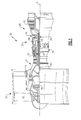
- FIG. 1 schematically illustrates a gas turbine engine 20, which is an example turbomachine.
- the gas turbine engine 20 is a two-spool turbofan having a fan section 22, a compressor section 24, a combustor section 26, and a turbine section 28.
- the fan section 22 drives air along a bypass flowpath.
- the compressor section 24 drives air along a core flowpath for compression. Compressed air is communicated into the combustor section 26 then expanded in the turbine section 28.
- the engine 20 generally includes a low speed spool 30 and a high speed spool 32 mounted for rotation about longitudinal axis A.
- the low speed spool 30 generally includes an inner shaft 40 that rotatably couples a fan 42, a low pressure compressor 44 and a low pressure turbine 46.
- the inner shaft 40 is connected to the fan 42 through a geared architecture 48 to drive the fan 42 at a lower speed than the low speed spool 30.
- the high speed spool 32 includes an outer shaft 50 that rotatably couples a high pressure compressor 52 and high pressure turbine 54.
- a combustor 56 is arranged between the high pressure compressor 52 and the high pressure turbine 54.
- the inner shaft 40 and the outer shaft 50 are coaxial and rotate about axis A.
- the core airflow is compressed by the low pressure compressor 44 and the high pressure compressor 52.
- the compressed air is mixed with fuel in the combustor 56 and then expanded over the turbines 46, 54.
- the turbines 46, 54 rotationally drive the respective low speed spool 30 and high speed spool 32 in response to the expansion.
- gas turbine engine shown as a gas turbine engine in this example, it should be understood that the concepts described herein are not limited to use with gas turbine engines as the teachings may be applied to other types of turbomachines and other devices that include geared architectures.
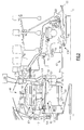
- the example geared architecture 48 generally includes a coupling shaft assembly 62 that transfers torque from the low speed spool 30 to the geared architecture 48.
- the example coupling shaft assembly 62 generally includes a forward coupling shaft section 64 and an aft coupling shaft section 66.
- the forward coupling shaft section 64 includes an interface spline 68 and a mid shaft interface spline 70.
- the aft coupling shaft section 66 includes a mid shaft interface spline 72 and an interface spline 74.
- the example geared architecture 48 also includes an epicyclic gear system 60 driven by the low speed spool 30 through the coupling shaft assembly 62.
- the interface spline 68 is joined, by a gear spline 76, to a sun gear 78 of the epicyclic gear system 60.
- the sun gear 78 is in meshed engagement with multiple intermediate gears, of which the illustrated star gear 86 is representative.
- Other examples may include other gears, such as planetary gears.
- Each star gear 86 is rotatably mounted in a carrier 82 by a journal pin 80.
- Rotary motion of the sun gear 78 urges each star gear 86 to rotate about a respective longitudinal axis P.
- Journal pin 80 is held in place by locating pin 87 to allow attachment of each star gear 86 to the carrier 82.
- Each journal pin 80 has a pair of axial ends 122, 124 and an oil supply passage 126 extending an axial length along axis P.
- An oil pump 136 is shown schematically and communicates oil to the oil track 138.
- the oil track 138 includes inlets 140 and cavities 142. Oil enters the oil track 138 at inlets 140 and flows into cavities 142 defined within the oil track 138.
- the cavities 142 communicate oil to the oil supply passage 126 of each journal pin 80 at the aft axial side 124.
- the cavities 142 and oil supply passage 126 are pressurized by the oil pump 136, which forces the oil to move into chambers 148a, 148b, as will be described in further detail below.
- Each star gear 86 is also in meshed engagement with rotating ring gear 88, which is mechanically connected to a shaft 131.
- the star gears 86 mesh with both the rotating ring gear 88 and the rotating sun gear 78.
- the star gears 86 rotate about their respective axis P to drive the ring gear 88 to rotate about engine axis A.
- the rotation of the ring gear 88 is conveyed to the fan 42 ( Figure 1 ) through the fan shaft 131 to drive the fan 42 at a lower speed than the low speed spool 30.
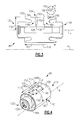
- the example journal pin 80 includes a generally cylindrical body 101 having an outer circumference 100.
- the oil supply passage 126 extends axially from the aft axial end 124 to the fore axial end 122 along axis P.
- oil is communicated to the oil supply passage 126 from the aft axial end 124.
- oil can be communicated into the oil supply passage 126 from the fore axial end 122.
- the oil supply passage 126 is pressurized by the oil pump 136 ( Fig. 2 ) such that oil in the oil supply passage 126 moves radially outward into chambers 148a, 148b.
- Each example chamber 148a, 148b extends from the oil supply passage 126 to the outer circumference 100 of the journal pin 80.
- Each chamber 148a, 148b includes an generally cylindrical inlet section 150 and a generally cylindrical holding section 152.
- the inlet section 150 is sized to control flow from the oil supply passage 126 to the outer circumference 100 of each journal pin 80.
- the circumferential size of inlet section 150 determines a maximum oil flow rate, and is dependent on the size of the journal pin 80.
- holding section 152 has a diameter and radial length greater than an inlet section 150.
- the cross sectional area of holding section 152 is 100 times the size of the area of inlet section 150.
- Inlet section 150 communicates oil to corresponding holding section 152, where oil is able to pool before being communicated via outlets 153 to the recess 154 disposed on the outer circumference 100 of the journal pin 80.
- the recess 154 holds oil to be distributed between the journal pin 80 and corresponding star gear 86 for lubrication.
- the recess includes axial ends 156 tapered at an angle ⁇ of 45° relative to axis P.
- an angle ⁇ of 40°-50° is contemplated.
- each journal pin 80 has an axial length 170 and a radius 172.
- the axial length 170 and radius 172 are determined based on the requirements of the engine 20.
- the recess 154 of each journal pin 80 includes a depth 158, an axial length 166, and a width 164.
- the ratio of the recess depth 158 to the radius 172 of the pin 80 is between .02:1 and .05:1. In one example, the ratio of the axial length 166 of each recess 154 to journal pin axial length 170 is between .4:1 and .5:1. Each recess has a width 164 which is between 40° and 45° of the outer circumference 100.
- a load plane 162 is defined on each journal pin 80 where oil pressure is the greatest on the journal pin 80, as will be described in further detail below.
- the holding sections 152 of respective chambers 148a, 148b are arranged such that the center of each chamber 148a, 148b, as shown by axis X, is an angle 160 between 95° and 110° from the load plane 162.
- Each chamber 148a, 148b is spaced from an axial end 156 of the recess 154 such that the distance between the center of each chamber 148a, 148b and axial ends 156 is 20% to 30% of the recess length 166.
- the recess 154 holds oil provided from the chambers 148a, 148b, allowing the journal pin 80 to supply the oil needed between journal pin 80 and respective star gear 86. To dispose of used or excess oil, oil is pushed to the axial ends 122, 124 of the journal pin 80 and falls off the axial ends 122, 124 of the journal pin.
- the chambers 148a, 148b are arranged symmetrically relative to the axial ends 156.
- the chambers 148a, 148b may also be arranged non-symmetrically to force oil to move off the journal pin 80 in a predetermined axial direction. Moving either chamber 148a, 148b in a first axial direction will force more oil to move off the journal pin 80 in the opposite second axial direction.
- oil pressure on the outer circumference 100 is increasing as oil moves from the recess 154 to the load plane 162.
- the oil pressure is at a maximum at the load plane 162 and then begins to decrease as the oil moves around the outer circumference 100 past the load plane 162.
- the oil is moving in a clockwise direction; however, rotation may also occur in a counterclockwise direction wherein the example recess 154 would be disposed the opposite side of the load plane 162.
- As oil moves about the outer circumference 100 it increases in temperature until it returns to the recess 154.
- the recess 154 pushes the heated oil moving about the outer circumference 100 to the axial ends 122, 124 of the journal pin 80 where it falls off the journal pin 80.
- Cool oil in the recess replaces the heated oil via viscous shearing.
- the heated oil that falls off the axial ends 122, 124 of the journal pin 80 then hits the fan shaft 131 ( Figure 2 ) and is scavenged.
- journal pin 80 allows the recess 154 to maintain a constant supply of oil even if one of the chambers 148a, 148b is blocked, or otherwise unable to provide oil from the oil supply passage 126. This allows the journal pin 80 to prevent failure during operation due to a lack of oil lubrication between the journal pin 80 and corresponding star gear 86.
- the pooling of oil in the recess 154 provides adequate oil supply during windmilling operation.
- the flow rate of oil within this configuration is also reduced, thereby reducing heat generation from excess oil being pushed off journal pins 80, which increases in temperature due to contact with other components in the engine 20.
- Engine 20 weight is also reduced by reduction of size of components, such as the oil pump 136, due to the decreased in oil flow rate.
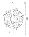
- rotating the sun gears 78 causes the star gears 86 to rotate around their respective journal pins 80.
- the example star gears 86 remain in the same circumferential position relative to the sun gear 78 while rotating.
- more or fewer star gears 86 may be used.
- the star gears 86 are equally circumferentially spaced about the sun gear 78.
- other orientations may be used.
- each star gear 86 As the sun gear 78 and ring gear 88 rotate, a force is applied to each star gear 86.
- the force applies a normal load, illustrated by arrows N to each journal pin 80 along the axial length of the journal pin 80.
- the direction of the normal load N applied to each journal pin 80 is determined based upon the orientation of each journal pin 80 relative to the sun gear 78.
- each recess 154 of respective journal pin 80 is offset by the angle 160 between 95° and 110° from the load plane 162.
- the recess 154 is circumferentially offset in a direction opposite the direction of rotation of corresponding star gear 86.
- a method of installing an epicyclic gear system in a turbomachine 202 includes supporting a first intermediate gear with a journal pin having a supply passage in fluid communication with a recess through a first chamber and a second chamber 204.
- the first chamber and second chamber are each radially outward of the supply passage and each of the first chamber and second chamber have a first section radially inward of a second section.
- a cross sectional area of the second section is greater than a cross sectional area of the first section.
- the journal pin is oriented so that the recess is circumferentially offset from a load plane of the journal pin 206.
- the journal pins and corresponding intermediate gears are rotated around the sun gear using a tool (not shown) inserted into the first journal pin.
- the corresponding intermediate gears are oriented relative to the first intermediate gear (See Fig. 5 ) about the sun gear.
- the intermediate gears form at least part of the epicyclic gear system 60 (See Fig. 2 ) which is attached to low speed spool 30 such that the sun gear 78 rotates with the low speed spool 30.
Abstract
Description
- This disclosure relates to a gear system and, in particular, to journal pins in an epicyclic gear system.
- Turbomachines, such as gas turbine engines, typically propel aircraft and include a fan section, a turbine section, a compressor section, and a combustor section. Turbomachines may employ an epicyclic gear system connecting the fan section and the turbine section. Journal pins hold planet (or star) gears between the sun gear and a ring gear. The journal pins connect the planet gears to a gear carrier.
- A single oil supply opening can supply outer surfaces of journal pins with oil to be distributed between the journal pin and the planet gears for lubrication. However, the use of a single supply opening necessitates an increased supply of oil, as well as increased oil pressure within the journal pin, for proper oil distribution. A single supply opening is also subject to blockage, resulting in bearing failure.
- An example journal pin includes a generally cylindrical body disposed on an axis having a supply passage. A first chamber and a second chamber are disposed in the generally cylindrical body and are in fluid communication with the supply passage. A recess on an outer diameter of the cylindrical body is in fluid communication with the first chamber and the second chamber. The first chamber and second chamber are each radially outward of the supply passage and including an outlet to the recess. The first chamber and second chamber each have a first section radially inward of a second section. A cross sectional area of the second section is greater than a cross sectional area of the corresponding first section.
- An example turbomachine epicyclic gear system includes a sun gear rotatable around an axis, a ring gear radially outward of the sun gear, and a plurality of intermediate gears meshed with the sun gear and the ring gear. A plurality of journal pins are each configured to support one of the plurality of intermediate gears. Each of the plurality of journal pins has a supply passage in fluid communication with a recess disposed on the outer circumference of each journal pin through a first chamber and a second chamber. The first chamber and second chamber are each radially outward of the supply passage and have an outlet to the recess. Each of the first chamber and second chamber have a first section radially inward of a second section. A cross sectional area of the second section is greater than a cross sectional area of the corresponding first section.
- An example method of installing an epicyclic gear system in a turbomachine includes supporting a first intermediate gear with a journal pin having a supply passage in fluid communication with a recess through a first chamber and a second chamber. The first chamber and second chamber are each radially outward of the supply passage. Each of the first chamber and second chamber have a first section radially inward of a second section. A cross sectional area of the second section is greater than a cross sectional area of the corresponding first section. The journal pin is oriented such that the recess is circumferentially offset from a load plane of the journal pin.
- Various features will become apparent to those skilled in the art from the following detailed description of the disclosed non-limiting embodiment. The drawings that accompany the detailed description can be briefly described as follows:
-
Figure 1 is a schematic cross-section of a turbomachine; -
Figure 2 is a close-up view of an epicyclic gear system within theFigure 1 turbomachine; -
Figure 3 is a cross-sectional view of an example journal pin; -
Figure 4 is a perspective view of the example journal pin ofFigure 3 ; -
Figure 5 is a cross sectional view of an example epicyclic gear system including the journal pin ofFigure 3 ; and -
Figure 6 shows an example method of installing an epicyclic gear system. -
Figure 1 schematically illustrates agas turbine engine 20, which is an example turbomachine. Thegas turbine engine 20 is a two-spool turbofan having afan section 22, acompressor section 24, acombustor section 26, and aturbine section 28. Thefan section 22 drives air along a bypass flowpath. Thecompressor section 24 drives air along a core flowpath for compression. Compressed air is communicated into thecombustor section 26 then expanded in theturbine section 28. Theengine 20 generally includes alow speed spool 30 and ahigh speed spool 32 mounted for rotation about longitudinal axis A. - The
low speed spool 30 generally includes aninner shaft 40 that rotatably couples afan 42, alow pressure compressor 44 and alow pressure turbine 46. Theinner shaft 40 is connected to thefan 42 through a gearedarchitecture 48 to drive thefan 42 at a lower speed than thelow speed spool 30. Thehigh speed spool 32 includes anouter shaft 50 that rotatably couples ahigh pressure compressor 52 andhigh pressure turbine 54. Acombustor 56 is arranged between thehigh pressure compressor 52 and thehigh pressure turbine 54. Theinner shaft 40 and theouter shaft 50 are coaxial and rotate about axis A. - The core airflow is compressed by the
low pressure compressor 44 and thehigh pressure compressor 52. The compressed air is mixed with fuel in thecombustor 56 and then expanded over theturbines turbines low speed spool 30 andhigh speed spool 32 in response to the expansion. Although shown as a gas turbine engine in this example, it should be understood that the concepts described herein are not limited to use with gas turbine engines as the teachings may be applied to other types of turbomachines and other devices that include geared architectures. - With reference to
Figure 2 , the example gearedarchitecture 48 generally includes acoupling shaft assembly 62 that transfers torque from thelow speed spool 30 to the gearedarchitecture 48. The examplecoupling shaft assembly 62 generally includes a forwardcoupling shaft section 64 and an aftcoupling shaft section 66. The forwardcoupling shaft section 64 includes aninterface spline 68 and a midshaft interface spline 70. The aftcoupling shaft section 66 includes a midshaft interface spline 72 and aninterface spline 74. - The example geared
architecture 48 also includes anepicyclic gear system 60 driven by thelow speed spool 30 through thecoupling shaft assembly 62. Theinterface spline 68 is joined, by agear spline 76, to asun gear 78 of theepicyclic gear system 60. Thesun gear 78 is in meshed engagement with multiple intermediate gears, of which the illustratedstar gear 86 is representative. Other examples may include other gears, such as planetary gears. - Each
star gear 86 is rotatably mounted in acarrier 82 by ajournal pin 80. Rotary motion of thesun gear 78 urges eachstar gear 86 to rotate about a respective longitudinal axisP. Journal pin 80 is held in place by locatingpin 87 to allow attachment of eachstar gear 86 to thecarrier 82. Eachjournal pin 80 has a pair ofaxial ends oil supply passage 126 extending an axial length along axis P. - An
oil pump 136 is shown schematically and communicates oil to theoil track 138. Theoil track 138 includesinlets 140 andcavities 142. Oil enters theoil track 138 atinlets 140 and flows intocavities 142 defined within theoil track 138. Thecavities 142 communicate oil to theoil supply passage 126 of eachjournal pin 80 at the aftaxial side 124. Thecavities 142 andoil supply passage 126 are pressurized by theoil pump 136, which forces the oil to move intochambers - Each
star gear 86 is also in meshed engagement withrotating ring gear 88, which is mechanically connected to ashaft 131. The star gears 86 mesh with both therotating ring gear 88 and therotating sun gear 78. The star gears 86 rotate about their respective axis P to drive thering gear 88 to rotate about engine axis A. The rotation of thering gear 88 is conveyed to the fan 42 (Figure 1 ) through thefan shaft 131 to drive thefan 42 at a lower speed than thelow speed spool 30. - Referring now to
Figures 3 and 4 , with continuing reference toFigure 2 , theexample journal pin 80 includes a generallycylindrical body 101 having anouter circumference 100. Theoil supply passage 126 extends axially from the aftaxial end 124 to the foreaxial end 122 along axis P. In theexample journal pin 80, oil is communicated to theoil supply passage 126 from the aftaxial end 124. Alternatively, oil can be communicated into theoil supply passage 126 from the foreaxial end 122. Theoil supply passage 126 is pressurized by the oil pump 136 (Fig. 2 ) such that oil in theoil supply passage 126 moves radially outward intochambers - Each
example chamber oil supply passage 126 to theouter circumference 100 of thejournal pin 80. Eachchamber cylindrical inlet section 150 and a generallycylindrical holding section 152. Theinlet section 150 is sized to control flow from theoil supply passage 126 to theouter circumference 100 of eachjournal pin 80. The circumferential size ofinlet section 150 determines a maximum oil flow rate, and is dependent on the size of thejournal pin 80. - In the
example journal pin 80, holdingsection 152 has a diameter and radial length greater than aninlet section 150. In one example, the cross sectional area of holdingsection 152 is 100 times the size of the area ofinlet section 150. However, other configurations of aholding section 152 having a greater cross section theninlet section 150 are contemplated.Inlet section 150 communicates oil to corresponding holdingsection 152, where oil is able to pool before being communicated viaoutlets 153 to therecess 154 disposed on theouter circumference 100 of thejournal pin 80. Therecess 154 holds oil to be distributed between thejournal pin 80 andcorresponding star gear 86 for lubrication. - In one example, the recess includes axial ends 156 tapered at an angle θ of 45° relative to axis P. However, an angle θ of 40°-50° is contemplated.
- The
cylindrical body 101 of eachjournal pin 80 has anaxial length 170 and aradius 172. Theaxial length 170 andradius 172 are determined based on the requirements of theengine 20. Therecess 154 of eachjournal pin 80 includes adepth 158, anaxial length 166, and awidth 164. - In one example, the ratio of the
recess depth 158 to theradius 172 of thepin 80 is between .02:1 and .05:1. In one example, the ratio of theaxial length 166 of eachrecess 154 to journal pinaxial length 170 is between .4:1 and .5:1. Each recess has awidth 164 which is between 40° and 45° of theouter circumference 100. - A
load plane 162 is defined on eachjournal pin 80 where oil pressure is the greatest on thejournal pin 80, as will be described in further detail below. The holdingsections 152 ofrespective chambers chamber angle 160 between 95° and 110° from theload plane 162. Eachchamber axial end 156 of therecess 154 such that the distance between the center of eachchamber recess length 166. - The
recess 154 holds oil provided from thechambers journal pin 80 to supply the oil needed betweenjournal pin 80 andrespective star gear 86. To dispose of used or excess oil, oil is pushed to the axial ends 122, 124 of thejournal pin 80 and falls off the axial ends 122, 124 of the journal pin. - In one example, the
chambers chambers journal pin 80 in a predetermined axial direction. Moving eitherchamber journal pin 80 in the opposite second axial direction. - During operation, oil pressure on the
outer circumference 100 is increasing as oil moves from therecess 154 to theload plane 162. The oil pressure is at a maximum at theload plane 162 and then begins to decrease as the oil moves around theouter circumference 100 past theload plane 162. In this example, the oil is moving in a clockwise direction; however, rotation may also occur in a counterclockwise direction wherein theexample recess 154 would be disposed the opposite side of theload plane 162. As oil moves about theouter circumference 100, it increases in temperature until it returns to therecess 154. Therecess 154 pushes the heated oil moving about theouter circumference 100 to the axial ends 122, 124 of thejournal pin 80 where it falls off thejournal pin 80. Cool oil in the recess replaces the heated oil via viscous shearing. The heated oil that falls off the axial ends 122, 124 of thejournal pin 80 then hits the fan shaft 131 (Figure 2 ) and is scavenged. - The use of two
chambers example journal pin 80 allows therecess 154 to maintain a constant supply of oil even if one of thechambers oil supply passage 126. This allows thejournal pin 80 to prevent failure during operation due to a lack of oil lubrication between thejournal pin 80 and corresponding star gear 86.The pooling of oil in therecess 154 provides adequate oil supply during windmilling operation. The flow rate of oil within this configuration is also reduced, thereby reducing heat generation from excess oil being pushed off journal pins 80, which increases in temperature due to contact with other components in theengine 20.Engine 20 weight is also reduced by reduction of size of components, such as theoil pump 136, due to the decreased in oil flow rate. - Referring to
Figure 5 , with continued reference toFigures 2-4 , rotating the sun gears 78 causes the star gears 86 to rotate around their respective journal pins 80. The example star gears 86 remain in the same circumferential position relative to thesun gear 78 while rotating. In this example, there are five star gears 86 radially oriented about thesun gear 78. However, more or fewer star gears 86 may be used. Also, the star gears 86 are equally circumferentially spaced about thesun gear 78. However, other orientations may be used. - As the
sun gear 78 andring gear 88 rotate, a force is applied to eachstar gear 86. The force applies a normal load, illustrated by arrows N to eachjournal pin 80 along the axial length of thejournal pin 80. The direction of the normal load N applied to eachjournal pin 80 is determined based upon the orientation of eachjournal pin 80 relative to thesun gear 78. - As the normal load N is applied during operation, it provides the greatest oil pressure on
load plane 162. The center of eachrecess 154 ofrespective journal pin 80 is offset by theangle 160 between 95° and 110° from theload plane 162. Therecess 154 is circumferentially offset in a direction opposite the direction of rotation of correspondingstar gear 86. - Referring to
Figure 6 , a method of installing an epicyclic gear system in aturbomachine 202 includes supporting a first intermediate gear with a journal pin having a supply passage in fluid communication with a recess through a first chamber and asecond chamber 204. The first chamber and second chamber are each radially outward of the supply passage and each of the first chamber and second chamber have a first section radially inward of a second section. In each chamber, a cross sectional area of the second section is greater than a cross sectional area of the first section. The journal pin is oriented so that the recess is circumferentially offset from a load plane of thejournal pin 206. The journal pins and corresponding intermediate gears are rotated around the sun gear using a tool (not shown) inserted into the first journal pin. The corresponding intermediate gears are oriented relative to the first intermediate gear (SeeFig. 5 ) about the sun gear. The intermediate gears form at least part of the epicyclic gear system 60 (SeeFig. 2 ) which is attached tolow speed spool 30 such that thesun gear 78 rotates with thelow speed spool 30. - Various non-limiting embodiments are disclosed herein, however, one of ordinary skill in the art would recognize that various modifications and variations in light of the above teachings will fall within the scope of the claims. For that reason, the following claims should be studied to determine their true scope and content.
Claims (15)
- A journal pin (80) comprising:a generally cylindrical body (101) disposed about an axis (P) having a supply passage (126);a first chamber (148a) and a second chamber (148b) disposed in the generally cylindrical body (101) in fluid communication with the supply passage (126); anda recess (154) on an outer diameter (100) of the cylindrical body (101) in fluid communication with the first chamber (148a) and the second chamber (148b), wherein the first chamber (148a) and second chamber (148b) are each radially outward of the supply passage (126) and include an outlet (153) to the recess (154), each of the first chamber (148a) and second chamber (148b) having a first section (150) radially inward of a second section (152), wherein a cross sectional area of the second section (152) is greater than a cross sectional area of the corresponding first section (150).
- The journal pin of claim 1, wherein a ratio of an axial length (166) of the recess (154) to an axial length (170) of the body is between .4:1 and .5:1.
- The journal pin of claim 1 or 2, wherein a ratio of a radial depth (158) of the recess (154) to a radius (172) of the cylindrical body (101) is between .02:1 and .05:1.
- The journal pin of any preceding claim, wherein the first chamber (148a) and the second chamber (148b) are symmetrically aligned relative to the axial ends (156) of the recess (154).
- The journal pin of any of claims 1 to 3, wherein the first chamber (148a) and the second chamber (148b) are non-symmetrically aligned relative to the axial ends (156) of the recess (154).
- The journal pin of any preceding claim, wherein a first axial end (156) and a second axial end (156) of the recess (154) are tapered.
- The journal pin of claim 6, wherein the taper of the first axial end (156) and second axial end (156) of the recess (154) being, for example, at an angle between 40° and 50°.
- The journal pin of any preceding claim, wherein the cross sectional area of the second section (152) is 100 times the cross sectional area of the first section (150).
- A turbomachine epicyclic gear system (60) comprising:a sun gear (78) rotatable around an axis and optionally rotatably driven by a low speed spool (30);a ring gear (88) radially outward of the sun gear (78);a plurality of intermediate gears (86) meshed with the sun gear (78) and the ring gear (88); anda plurality of journal pins (80) as claimed in any preceding claim, each configured to support one of the plurality of intermediate gears (86).
- The turbomachine epicyclic gear system of claim 9, wherein each journal pin (80) has a load plane (162) circumferentially aligned with a normal load (N) applied to the journal pins (80), wherein the normal load is perpendicular to the axis.
- The turbomachine epicyclic gear system of claim 10, wherein a center of the first chamber (148a) and a center of the second chamber (148b) are between 95° and 110° circumferentially offset from the load plane (162).
- The turbomachine epicyclic gear system of claim 8, 9 or 10, wherein an oil track (138) is in fluid communication with the supply passage (126) to communicate oil from an oil source (136) to the supply passage (126), and wherein, optionally the oil track (138) supplies oil to the supply passage (126) at an axially aft end of the supply passage (126).
- The turbomachine epicyclic gear system of any of claims 9 to 12, wherein the epicyclic gear system (60) includes five intermediate gears (86) circumferentially spaced equally about the sun gear (78), and/or wherein each journal pin (80) attaches the corresponding intermediate gear (86) to a carrier (82), the corresponding intermediate gear (86) configured to rotate relative to the journal pin (80).
- A method for assembling an epicyclic gear system (60) in a turbomachine comprising:supporting a first intermediate gear (86) with a journal pin (80) having a supply passage (126) in fluid communication with a recess (154) through a first chamber (148a) and a second chamber (148b) disposed in the journal pin (80), wherein the first chamber (148a) and second chamber (148b) are each radially outward of the supply passage (126), each of the first chamber (148a) and second chamber (148b) having a first section (152) radially inward of a second section (150), wherein a cross sectional area of the second section (152) is greater than a cross sectional area of the corresponding first section (150); andorienting the journal pin (80) such that the recess (154) is circumferentially offset from a load plane (162) of the journal pin (80).
- The method of claim 14, further comprising inserting the first intermediate gear (86) and a plurality of additional intermediate gears (86) onto the epicyclic gear system (60), and/or attaching the epicyclic gear system (60) to communicate with a low pressure turbine shaft (30) such that a sun gear (78) of the system rotates with the low pressure turbine shaft (30, and/or further comprising orienting a plurality of additional intermediate gears (86) with corresponding journal pins (80) relative to the orientation of the first intermediate gear (86).
Applications Claiming Priority (1)
| Application Number | Priority Date | Filing Date | Title |
|---|---|---|---|
| US13/196,114 US8690721B2 (en) | 2011-08-02 | 2011-08-02 | Journal pin oil supply for gear system |
Publications (3)
| Publication Number | Publication Date |
|---|---|
| EP2554874A2 true EP2554874A2 (en) | 2013-02-06 |
| EP2554874A3 EP2554874A3 (en) | 2013-05-22 |
| EP2554874B1 EP2554874B1 (en) | 2014-07-16 |
Family
ID=46982389
Family Applications (1)
| Application Number | Title | Priority Date | Filing Date |
|---|---|---|---|
| EP12178865.7A Active EP2554874B1 (en) | 2011-08-02 | 2012-08-01 | Journal pin oil supply for gear system and method for assembling |
Country Status (2)
| Country | Link |
|---|---|
| US (2) | US8690721B2 (en) |
| EP (1) | EP2554874B1 (en) |
Cited By (9)
| Publication number | Priority date | Publication date | Assignee | Title |
|---|---|---|---|---|
| WO2015108709A1 (en) | 2014-01-20 | 2015-07-23 | United Technologies Corporation | Lightweight journal support pin |
| EP3029358A1 (en) * | 2014-12-01 | 2016-06-08 | United Technologies Corporation | Lightweight and compliant journal pin |
| EP3093467A1 (en) * | 2015-05-05 | 2016-11-16 | United Technologies Corporation | Lubrication system for geared gas turbine engine |
| EP3354884A1 (en) * | 2017-01-30 | 2018-08-01 | United Technologies Corporation | Lubrication of epicyclic gear system for gas turbine engine |
| FR3071293A1 (en) * | 2017-09-19 | 2019-03-22 | Safran Transmission Systems | TURBOMACHINE PLANETARY OR EPICYCLOIDAL TRAIN SPEED REDUCER |
| CN109973510A (en) * | 2017-12-27 | 2019-07-05 | 苏州唐锟辰新能源科技有限公司 | A kind of big profile shaft and its processing method with flange |
| EP3705705A1 (en) | 2019-03-07 | 2020-09-09 | Safran Aircraft Engines | Mechanical gear of an aircraft turbine engine |
| US11137063B2 (en) * | 2019-04-19 | 2021-10-05 | Safran Transmission Systems | Mechanical reduction gear for aircraft turbomachine |
| IT202100015386A1 (en) * | 2021-06-11 | 2022-12-11 | Ge Avio Srl | TURBOMACHINES AND PLANETARY GEAR SETS WITH LUBRICATION CHANNELS |
Families Citing this family (25)
| Publication number | Priority date | Publication date | Assignee | Title |
|---|---|---|---|---|
| US9163717B2 (en) * | 2012-04-30 | 2015-10-20 | United Technologies Corporation | Multi-piece fluid manifold for gas turbine engine |
| US9416866B2 (en) * | 2014-07-17 | 2016-08-16 | Baldor Electric Company | Vertical gear motor planetary gear lubrication system |
| US9528596B2 (en) | 2014-08-06 | 2016-12-27 | Baldor Electric Company | Gear box with clutch having spring engagement and hydraulic disengagement |
| US9797499B2 (en) | 2014-08-12 | 2017-10-24 | Baldor Electric Company | Method of installing a motor on a gear box |
| US9528594B2 (en) | 2014-09-04 | 2016-12-27 | Baldor Electric Company | Lubrication system for a gear box and associated methods |
| US10234018B2 (en) * | 2015-10-19 | 2019-03-19 | General Electric Company | Planet gearbox with cylindrical roller bearing with under race lube scheme |
| US10641332B2 (en) * | 2016-12-06 | 2020-05-05 | General Electric Company | Roller element bearing with preloaded hydrodynamic cage guides |
| US10526976B2 (en) * | 2017-04-27 | 2020-01-07 | United Technologies Corporation | Tangential drive for gas turbine engine accessories |
| FR3071025B1 (en) * | 2017-09-12 | 2021-02-12 | Safran Trans Systems | PIVOT FOR SLIDING BEARINGS AND REDUCED THERMAL STRESS GEAR TRAIN |
| US10851671B2 (en) | 2019-03-29 | 2020-12-01 | Pratt & Whitney Canada Corp. | Bending stiffening feature used for compliant journal bearing |
| US10935076B2 (en) | 2019-05-03 | 2021-03-02 | Pratt & Whitney Canada Corp. | Journal bearing assembly with dual oil cavities |
| DE102020116522A1 (en) | 2020-06-23 | 2021-12-23 | Rolls-Royce Deutschland Ltd & Co Kg | Planetary gear |
| FR3114367B1 (en) * | 2020-09-23 | 2022-12-02 | Safran Trans Systems | Improved reducer for crown retention. |
| DE102021115337A1 (en) | 2021-06-14 | 2022-12-15 | Rolls-Royce Deutschland Ltd & Co Kg | Planetary gear of a gas turbine engine |
| US11821364B2 (en) * | 2021-08-20 | 2023-11-21 | Pratt & Whitney Canada Corp. | Shaped cavity at interface between journal bearing and rotor |
| US11814975B2 (en) | 2021-08-20 | 2023-11-14 | Pratt & Whitney Canada Corp. | Feed circuit with slot(s) at interface between journal bearing and rotor |
| US11680525B2 (en) | 2021-08-20 | 2023-06-20 | Pratt & Whitney Canada Corp. | Lubricant filter for a turbine engine |
| DE102021122169A1 (en) * | 2021-08-26 | 2023-03-02 | Rolls-Royce Deutschland Ltd & Co Kg | Plain bearing and method for lubricating and cooling a plain bearing |
| DE102021122156A1 (en) * | 2021-08-26 | 2023-03-02 | Rolls-Royce Deutschland Ltd & Co Kg | Plain bearing and method for lubricating and cooling a plain bearing |
| DE102021122164A1 (en) * | 2021-08-26 | 2023-03-02 | Rolls-Royce Deutschland Ltd & Co Kg | Plain bearing and method for lubricating and cooling a plain bearing |
| DE102021122146A1 (en) | 2021-08-26 | 2023-03-02 | Rolls-Royce Deutschland Ltd & Co Kg | planetary gear |
| DE102021122161A1 (en) * | 2021-08-26 | 2023-03-02 | Rolls-Royce Deutschland Ltd & Co Kg | Plain bearing and method for lubricating and cooling a plain bearing |
| DE102021134169A1 (en) | 2021-12-21 | 2023-06-22 | Rolls-Royce Deutschland Ltd & Co Kg | Planetary gear for a gas turbine engine and gas turbine engine |
| US20230313706A1 (en) * | 2022-03-29 | 2023-10-05 | Pratt & Whitney Canada Corp. | Journal bearing with oil pocket |
| US11933228B2 (en) | 2022-07-13 | 2024-03-19 | General Electric Company | Gearbox assembly |
Family Cites Families (18)
| Publication number | Priority date | Publication date | Assignee | Title |
|---|---|---|---|---|
| JP2516967B2 (en) * | 1987-04-30 | 1996-07-24 | 松下電器産業株式会社 | Bearing device |
| US5102379A (en) | 1991-03-25 | 1992-04-07 | United Technologies Corporation | Journal bearing arrangement |
| US5482380A (en) | 1994-08-24 | 1996-01-09 | Corratti; Anthony A. | Double tilting pad journal bearing |
| ES2202372T3 (en) * | 1994-09-08 | 2004-04-01 | Kawasaki Jukogyo Kabushiki Kaisha | DRIVE-ROTARY BEARING FOR DRIVE AGAINST-ROTARY. |
| US7704178B2 (en) | 2006-07-05 | 2010-04-27 | United Technologies Corporation | Oil baffle for gas turbine fan drive gear system |
| US8585538B2 (en) * | 2006-07-05 | 2013-11-19 | United Technologies Corporation | Coupling system for a star gear train in a gas turbine engine |
| US7662059B2 (en) | 2006-10-18 | 2010-02-16 | United Technologies Corporation | Lubrication of windmilling journal bearings |
| US8020665B2 (en) | 2006-11-22 | 2011-09-20 | United Technologies Corporation | Lubrication system with extended emergency operability |
| US8215454B2 (en) | 2006-11-22 | 2012-07-10 | United Technologies Corporation | Lubrication system with tolerance for reduced gravity |
| US20080268997A1 (en) * | 2007-04-24 | 2008-10-30 | Gooden James T | Lubrication path in a planetary gear unit for a transmission |
| JP2009197821A (en) | 2008-02-19 | 2009-09-03 | Nsk Ltd | Planetary gear mechanism |
| US8398517B2 (en) * | 2009-06-10 | 2013-03-19 | United Technologies Corporation | Journal bearing with single unit jumper tube and filter |
| US8246503B2 (en) * | 2009-06-10 | 2012-08-21 | United Technologies Corporation | Epicyclic gear system with improved lubrication system |
| US8172716B2 (en) | 2009-06-25 | 2012-05-08 | United Technologies Corporation | Epicyclic gear system with superfinished journal bearing |
| US8333678B2 (en) | 2009-06-26 | 2012-12-18 | United Technologies Corporation | Epicyclic gear system with load share reduction |
| DK2383480T3 (en) * | 2010-04-30 | 2013-01-21 | Winergy Ag | Planetary gear for a wind turbine |
| US9541007B2 (en) * | 2011-04-15 | 2017-01-10 | United Technologies Corporation | Coupling shaft for gas turbine fan drive gear system |
| US8899916B2 (en) * | 2011-08-30 | 2014-12-02 | United Technologies Corporation | Torque frame and asymmetric journal bearing for fan drive gear system |
-
2011
- 2011-08-02 US US13/196,114 patent/US8690721B2/en active Active
-
2012
- 2012-08-01 EP EP12178865.7A patent/EP2554874B1/en active Active
-
2014
- 2014-03-11 US US14/204,031 patent/US8894529B2/en active Active
Non-Patent Citations (1)
| Title |
|---|
| None |
Cited By (23)
| Publication number | Priority date | Publication date | Assignee | Title |
|---|---|---|---|---|
| US10526909B2 (en) | 2014-01-20 | 2020-01-07 | United Technologies Corporation | Lightweight journal support pin |
| EP3097324A4 (en) * | 2014-01-20 | 2016-12-28 | United Technologies Corp | Lightweight journal support pin |
| US11697999B2 (en) | 2014-01-20 | 2023-07-11 | Raytheon Technologies Corporation | Lightweight journal support pin |
| US11555412B2 (en) | 2014-01-20 | 2023-01-17 | Raytheon Technologies Corporation | Lightweight journal support pin |
| EP3097324B1 (en) | 2014-01-20 | 2019-04-03 | United Technologies Corporation | Lightweight journal support pin |
| WO2015108709A1 (en) | 2014-01-20 | 2015-07-23 | United Technologies Corporation | Lightweight journal support pin |
| EP3029358A1 (en) * | 2014-12-01 | 2016-06-08 | United Technologies Corporation | Lightweight and compliant journal pin |
| US9982771B2 (en) | 2014-12-01 | 2018-05-29 | United Technologies Corporation | Lightweight and compliant journal pin |
| US10240671B2 (en) | 2014-12-01 | 2019-03-26 | United Technologies Corporation | Lightweight and compliant journal pin |
| EP3093467A1 (en) * | 2015-05-05 | 2016-11-16 | United Technologies Corporation | Lubrication system for geared gas turbine engine |
| US9777595B2 (en) | 2015-05-05 | 2017-10-03 | United Technologies Corporation | Lubrication system for geared gas turbine engine |
| EP3872328A1 (en) * | 2017-01-30 | 2021-09-01 | Raytheon Technologies Corporation | Lubrication of epicyclic gear system for gas turbine engine |
| US10494998B2 (en) | 2017-01-30 | 2019-12-03 | United Technologies Corporation | Lubrication of epicyclic gear system for gas turbine engine |
| US11401864B2 (en) | 2017-01-30 | 2022-08-02 | Raytheon Technologies Corporation | Lubrication of epicyclic gear system for gas turbine engine |
| EP3354884A1 (en) * | 2017-01-30 | 2018-08-01 | United Technologies Corporation | Lubrication of epicyclic gear system for gas turbine engine |
| FR3071293A1 (en) * | 2017-09-19 | 2019-03-22 | Safran Transmission Systems | TURBOMACHINE PLANETARY OR EPICYCLOIDAL TRAIN SPEED REDUCER |
| CN109973510A (en) * | 2017-12-27 | 2019-07-05 | 苏州唐锟辰新能源科技有限公司 | A kind of big profile shaft and its processing method with flange |
| EP3705705A1 (en) | 2019-03-07 | 2020-09-09 | Safran Aircraft Engines | Mechanical gear of an aircraft turbine engine |
| FR3093550A1 (en) * | 2019-03-07 | 2020-09-11 | Safran Aircraft Engines | AIRCRAFT TURBOMACHINE MECHANICAL REDUCER |
| US11396846B2 (en) | 2019-03-07 | 2022-07-26 | Safran Aircraft Engines | Aircraft turbine engine mechanical reduction gear |
| US11137063B2 (en) * | 2019-04-19 | 2021-10-05 | Safran Transmission Systems | Mechanical reduction gear for aircraft turbomachine |
| IT202100015386A1 (en) * | 2021-06-11 | 2022-12-11 | Ge Avio Srl | TURBOMACHINES AND PLANETARY GEAR SETS WITH LUBRICATION CHANNELS |
| US11920491B2 (en) | 2021-06-11 | 2024-03-05 | Ge Avio S.R.L. | Turbomachines and epicyclic gear assemblies with lubrication channels |
Also Published As
| Publication number | Publication date |
|---|---|
| US8894529B2 (en) | 2014-11-25 |
| US20130035190A1 (en) | 2013-02-07 |
| EP2554874B1 (en) | 2014-07-16 |
| US8690721B2 (en) | 2014-04-08 |
| EP2554874A3 (en) | 2013-05-22 |
| US20140194240A1 (en) | 2014-07-10 |
Similar Documents
| Publication | Publication Date | Title |
|---|---|---|
| EP2554874B1 (en) | Journal pin oil supply for gear system and method for assembling | |
| EP3869064B1 (en) | Planetary gearbox having compliant journal bearings | |
| EP2994666B1 (en) | Fan drive gear system with improved misalignment capability | |
| EP3636899B1 (en) | Coupling shaft for gas turbine fan drive gear system | |
| EP2915962B1 (en) | Geared turbofan with integral front support and carrier | |
| EP3524796B1 (en) | Fan drive gear system including a two-piece fan shaft with lubricant transfer leakage recapture and corresponding assembly method | |
| US11208958B2 (en) | Method of assembly for fan drive gear system with rotating carrier | |
| EP3070377B1 (en) | Zero or low leakage oil transfer bearing | |
| EP2587020B1 (en) | Journal pin for gear system | |
| US10533522B2 (en) | Load balanced journal bearing pin | |
| EP3036420B1 (en) | Load balanced journal bearing pin | |
| EP3004599B1 (en) | Manifold for gas turbine | |
| EP3447247B1 (en) | Gas turbine engine assembly comprising damped fluid transfer tube | |
| EP3626935B1 (en) | A speed change mechanism for a gas turbine engine |
Legal Events
| Date | Code | Title | Description |
|---|---|---|---|
| PUAI | Public reference made under article 153(3) epc to a published international application that has entered the european phase |
Free format text: ORIGINAL CODE: 0009012 |
|
| AK | Designated contracting states |
Kind code of ref document: A2 Designated state(s): AL AT BE BG CH CY CZ DE DK EE ES FI FR GB GR HR HU IE IS IT LI LT LU LV MC MK MT NL NO PL PT RO RS SE SI SK SM TR |
|
| AX | Request for extension of the european patent |
Extension state: BA ME |
|
| PUAL | Search report despatched |
Free format text: ORIGINAL CODE: 0009013 |
|
| AK | Designated contracting states |
Kind code of ref document: A3 Designated state(s): AL AT BE BG CH CY CZ DE DK EE ES FI FR GB GR HR HU IE IS IT LI LT LU LV MC MK MT NL NO PL PT RO RS SE SI SK SM TR |
|
| AX | Request for extension of the european patent |
Extension state: BA ME |
|
| RIC1 | Information provided on ipc code assigned before grant |
Ipc: F16H 57/08 20060101AFI20130412BHEP |
|
| REG | Reference to a national code |
Ref country code: DE Ref legal event code: R079 Ref document number: 602012002422 Country of ref document: DE Free format text: PREVIOUS MAIN CLASS: F16H0057080000 Ipc: F16C0003020000 |
|
| 17P | Request for examination filed |
Effective date: 20131122 |
|
| RBV | Designated contracting states (corrected) |
Designated state(s): AL AT BE BG CH CY CZ DE DK EE ES FI FR GB GR HR HU IE IS IT LI LT LU LV MC MK MT NL NO PL PT RO RS SE SI SK SM TR |
|
| RIC1 | Information provided on ipc code assigned before grant |
Ipc: F16H 57/04 20100101ALI20131216BHEP Ipc: F16C 3/02 20060101AFI20131216BHEP Ipc: F16H 57/08 20060101ALI20131216BHEP Ipc: F02C 7/32 20060101ALI20131216BHEP |
|
| GRAP | Despatch of communication of intention to grant a patent |
Free format text: ORIGINAL CODE: EPIDOSNIGR1 |
|
| INTG | Intention to grant announced |
Effective date: 20140206 |
|
| GRAS | Grant fee paid |
Free format text: ORIGINAL CODE: EPIDOSNIGR3 |
|
| GRAA | (expected) grant |
Free format text: ORIGINAL CODE: 0009210 |
|
| AK | Designated contracting states |
Kind code of ref document: B1 Designated state(s): AL AT BE BG CH CY CZ DE DK EE ES FI FR GB GR HR HU IE IS IT LI LT LU LV MC MK MT NL NO PL PT RO RS SE SI SK SM TR |
|
| REG | Reference to a national code |
Ref country code: GB Ref legal event code: FG4D |
|
| REG | Reference to a national code |
Ref country code: CH Ref legal event code: EP |
|
| REG | Reference to a national code |
Ref country code: IE Ref legal event code: FG4D |
|
| REG | Reference to a national code |
Ref country code: AT Ref legal event code: REF Ref document number: 677843 Country of ref document: AT Kind code of ref document: T Effective date: 20140815 |
|
| REG | Reference to a national code |
Ref country code: DE Ref legal event code: R096 Ref document number: 602012002422 Country of ref document: DE Effective date: 20140904 |
|
| REG | Reference to a national code |
Ref country code: NL Ref legal event code: VDEP Effective date: 20140716 |
|
| REG | Reference to a national code |
Ref country code: AT Ref legal event code: MK05 Ref document number: 677843 Country of ref document: AT Kind code of ref document: T Effective date: 20140716 |
|
| REG | Reference to a national code |
Ref country code: LT Ref legal event code: MG4D |
|
| PG25 | Lapsed in a contracting state [announced via postgrant information from national office to epo] |
Ref country code: NO Free format text: LAPSE BECAUSE OF FAILURE TO SUBMIT A TRANSLATION OF THE DESCRIPTION OR TO PAY THE FEE WITHIN THE PRESCRIBED TIME-LIMIT Effective date: 20141016 Ref country code: BG Free format text: LAPSE BECAUSE OF FAILURE TO SUBMIT A TRANSLATION OF THE DESCRIPTION OR TO PAY THE FEE WITHIN THE PRESCRIBED TIME-LIMIT Effective date: 20141016 Ref country code: LT Free format text: LAPSE BECAUSE OF FAILURE TO SUBMIT A TRANSLATION OF THE DESCRIPTION OR TO PAY THE FEE WITHIN THE PRESCRIBED TIME-LIMIT Effective date: 20140716 Ref country code: GR Free format text: LAPSE BECAUSE OF FAILURE TO SUBMIT A TRANSLATION OF THE DESCRIPTION OR TO PAY THE FEE WITHIN THE PRESCRIBED TIME-LIMIT Effective date: 20141017 Ref country code: FI Free format text: LAPSE BECAUSE OF FAILURE TO SUBMIT A TRANSLATION OF THE DESCRIPTION OR TO PAY THE FEE WITHIN THE PRESCRIBED TIME-LIMIT Effective date: 20140716 Ref country code: PT Free format text: LAPSE BECAUSE OF FAILURE TO SUBMIT A TRANSLATION OF THE DESCRIPTION OR TO PAY THE FEE WITHIN THE PRESCRIBED TIME-LIMIT Effective date: 20141117 Ref country code: ES Free format text: LAPSE BECAUSE OF FAILURE TO SUBMIT A TRANSLATION OF THE DESCRIPTION OR TO PAY THE FEE WITHIN THE PRESCRIBED TIME-LIMIT Effective date: 20140716 Ref country code: SE Free format text: LAPSE BECAUSE OF FAILURE TO SUBMIT A TRANSLATION OF THE DESCRIPTION OR TO PAY THE FEE WITHIN THE PRESCRIBED TIME-LIMIT Effective date: 20140716 |
|
| PG25 | Lapsed in a contracting state [announced via postgrant information from national office to epo] |
Ref country code: CY Free format text: LAPSE BECAUSE OF FAILURE TO SUBMIT A TRANSLATION OF THE DESCRIPTION OR TO PAY THE FEE WITHIN THE PRESCRIBED TIME-LIMIT Effective date: 20140716 Ref country code: LV Free format text: LAPSE BECAUSE OF FAILURE TO SUBMIT A TRANSLATION OF THE DESCRIPTION OR TO PAY THE FEE WITHIN THE PRESCRIBED TIME-LIMIT Effective date: 20140716 Ref country code: NL Free format text: LAPSE BECAUSE OF FAILURE TO SUBMIT A TRANSLATION OF THE DESCRIPTION OR TO PAY THE FEE WITHIN THE PRESCRIBED TIME-LIMIT Effective date: 20140716 Ref country code: RS Free format text: LAPSE BECAUSE OF FAILURE TO SUBMIT A TRANSLATION OF THE DESCRIPTION OR TO PAY THE FEE WITHIN THE PRESCRIBED TIME-LIMIT Effective date: 20140716 Ref country code: PL Free format text: LAPSE BECAUSE OF FAILURE TO SUBMIT A TRANSLATION OF THE DESCRIPTION OR TO PAY THE FEE WITHIN THE PRESCRIBED TIME-LIMIT Effective date: 20140716 Ref country code: AT Free format text: LAPSE BECAUSE OF FAILURE TO SUBMIT A TRANSLATION OF THE DESCRIPTION OR TO PAY THE FEE WITHIN THE PRESCRIBED TIME-LIMIT Effective date: 20140716 Ref country code: IS Free format text: LAPSE BECAUSE OF FAILURE TO SUBMIT A TRANSLATION OF THE DESCRIPTION OR TO PAY THE FEE WITHIN THE PRESCRIBED TIME-LIMIT Effective date: 20141116 |
|
| REG | Reference to a national code |
Ref country code: DE Ref legal event code: R097 Ref document number: 602012002422 Country of ref document: DE |
|
| PG25 | Lapsed in a contracting state [announced via postgrant information from national office to epo] |
Ref country code: EE Free format text: LAPSE BECAUSE OF FAILURE TO SUBMIT A TRANSLATION OF THE DESCRIPTION OR TO PAY THE FEE WITHIN THE PRESCRIBED TIME-LIMIT Effective date: 20140716 Ref country code: BE Free format text: LAPSE BECAUSE OF NON-PAYMENT OF DUE FEES Effective date: 20140831 Ref country code: RO Free format text: LAPSE BECAUSE OF FAILURE TO SUBMIT A TRANSLATION OF THE DESCRIPTION OR TO PAY THE FEE WITHIN THE PRESCRIBED TIME-LIMIT Effective date: 20140716 Ref country code: SK Free format text: LAPSE BECAUSE OF FAILURE TO SUBMIT A TRANSLATION OF THE DESCRIPTION OR TO PAY THE FEE WITHIN THE PRESCRIBED TIME-LIMIT Effective date: 20140716 Ref country code: MC Free format text: LAPSE BECAUSE OF FAILURE TO SUBMIT A TRANSLATION OF THE DESCRIPTION OR TO PAY THE FEE WITHIN THE PRESCRIBED TIME-LIMIT Effective date: 20140716 Ref country code: IT Free format text: LAPSE BECAUSE OF FAILURE TO SUBMIT A TRANSLATION OF THE DESCRIPTION OR TO PAY THE FEE WITHIN THE PRESCRIBED TIME-LIMIT Effective date: 20140716 Ref country code: CZ Free format text: LAPSE BECAUSE OF FAILURE TO SUBMIT A TRANSLATION OF THE DESCRIPTION OR TO PAY THE FEE WITHIN THE PRESCRIBED TIME-LIMIT Effective date: 20140716 Ref country code: DK Free format text: LAPSE BECAUSE OF FAILURE TO SUBMIT A TRANSLATION OF THE DESCRIPTION OR TO PAY THE FEE WITHIN THE PRESCRIBED TIME-LIMIT Effective date: 20140716 |
|
| REG | Reference to a national code |
Ref country code: IE Ref legal event code: MM4A |
|
| PLBE | No opposition filed within time limit |
Free format text: ORIGINAL CODE: 0009261 |
|
| STAA | Information on the status of an ep patent application or granted ep patent |
Free format text: STATUS: NO OPPOSITION FILED WITHIN TIME LIMIT |
|
| REG | Reference to a national code |
Ref country code: FR Ref legal event code: ST Effective date: 20150430 |
|
| 26N | No opposition filed |
Effective date: 20150417 |
|
| PG25 | Lapsed in a contracting state [announced via postgrant information from national office to epo] |
Ref country code: FR Free format text: LAPSE BECAUSE OF NON-PAYMENT OF DUE FEES Effective date: 20140916 Ref country code: IE Free format text: LAPSE BECAUSE OF NON-PAYMENT OF DUE FEES Effective date: 20140801 |
|
| PG25 | Lapsed in a contracting state [announced via postgrant information from national office to epo] |
Ref country code: SI Free format text: LAPSE BECAUSE OF FAILURE TO SUBMIT A TRANSLATION OF THE DESCRIPTION OR TO PAY THE FEE WITHIN THE PRESCRIBED TIME-LIMIT Effective date: 20140716 |
|
| REG | Reference to a national code |
Ref country code: CH Ref legal event code: PL |
|
| PG25 | Lapsed in a contracting state [announced via postgrant information from national office to epo] |
Ref country code: CH Free format text: LAPSE BECAUSE OF NON-PAYMENT OF DUE FEES Effective date: 20150831 Ref country code: LI Free format text: LAPSE BECAUSE OF NON-PAYMENT OF DUE FEES Effective date: 20150831 |
|
| PG25 | Lapsed in a contracting state [announced via postgrant information from national office to epo] |
Ref country code: SM Free format text: LAPSE BECAUSE OF FAILURE TO SUBMIT A TRANSLATION OF THE DESCRIPTION OR TO PAY THE FEE WITHIN THE PRESCRIBED TIME-LIMIT Effective date: 20140716 |
|
| PG25 | Lapsed in a contracting state [announced via postgrant information from national office to epo] |
Ref country code: MT Free format text: LAPSE BECAUSE OF FAILURE TO SUBMIT A TRANSLATION OF THE DESCRIPTION OR TO PAY THE FEE WITHIN THE PRESCRIBED TIME-LIMIT Effective date: 20140716 |
|
| PG25 | Lapsed in a contracting state [announced via postgrant information from national office to epo] |
Ref country code: BE Free format text: LAPSE BECAUSE OF FAILURE TO SUBMIT A TRANSLATION OF THE DESCRIPTION OR TO PAY THE FEE WITHIN THE PRESCRIBED TIME-LIMIT Effective date: 20140716 Ref country code: HU Free format text: LAPSE BECAUSE OF FAILURE TO SUBMIT A TRANSLATION OF THE DESCRIPTION OR TO PAY THE FEE WITHIN THE PRESCRIBED TIME-LIMIT; INVALID AB INITIO Effective date: 20120801 Ref country code: TR Free format text: LAPSE BECAUSE OF FAILURE TO SUBMIT A TRANSLATION OF THE DESCRIPTION OR TO PAY THE FEE WITHIN THE PRESCRIBED TIME-LIMIT Effective date: 20140716 Ref country code: LU Free format text: LAPSE BECAUSE OF NON-PAYMENT OF DUE FEES Effective date: 20140801 Ref country code: HR Free format text: LAPSE BECAUSE OF FAILURE TO SUBMIT A TRANSLATION OF THE DESCRIPTION OR TO PAY THE FEE WITHIN THE PRESCRIBED TIME-LIMIT Effective date: 20140716 |
|
| REG | Reference to a national code |
Ref country code: DE Ref legal event code: R082 Ref document number: 602012002422 Country of ref document: DE Representative=s name: SCHMITT-NILSON SCHRAUD WAIBEL WOHLFROM PATENTA, DE |
|
| REG | Reference to a national code |
Ref country code: DE Ref legal event code: R082 Ref document number: 602012002422 Country of ref document: DE Representative=s name: SCHMITT-NILSON SCHRAUD WAIBEL WOHLFROM PATENTA, DE Ref country code: DE Ref legal event code: R081 Ref document number: 602012002422 Country of ref document: DE Owner name: UNITED TECHNOLOGIES CORP. (N.D.GES.D. STAATES , US Free format text: FORMER OWNER: UNITED TECHNOLOGIES CORP., HARTFORD, CONN., US |
|
| PG25 | Lapsed in a contracting state [announced via postgrant information from national office to epo] |
Ref country code: MK Free format text: LAPSE BECAUSE OF FAILURE TO SUBMIT A TRANSLATION OF THE DESCRIPTION OR TO PAY THE FEE WITHIN THE PRESCRIBED TIME-LIMIT Effective date: 20140716 |
|
| PG25 | Lapsed in a contracting state [announced via postgrant information from national office to epo] |
Ref country code: AL Free format text: LAPSE BECAUSE OF FAILURE TO SUBMIT A TRANSLATION OF THE DESCRIPTION OR TO PAY THE FEE WITHIN THE PRESCRIBED TIME-LIMIT Effective date: 20140716 |
|
| REG | Reference to a national code |
Ref country code: DE Ref legal event code: R081 Ref document number: 602012002422 Country of ref document: DE Owner name: RAYTHEON TECHNOLOGIES CORPORATION (N.D.GES.D.S, US Free format text: FORMER OWNER: UNITED TECHNOLOGIES CORP. (N.D.GES.D. STAATES DELAWARE), FARMINGTON, CONN., US |
|
| P01 | Opt-out of the competence of the unified patent court (upc) registered |
Effective date: 20230520 |
|
| PGFP | Annual fee paid to national office [announced via postgrant information from national office to epo] |
Ref country code: GB Payment date: 20230720 Year of fee payment: 12 |
|
| PGFP | Annual fee paid to national office [announced via postgrant information from national office to epo] |
Ref country code: DE Payment date: 20230720 Year of fee payment: 12 |