EP2554823A1 - Fuel supply device of gas turbine engine - Google Patents
Fuel supply device of gas turbine engine Download PDFInfo
- Publication number
- EP2554823A1 EP2554823A1 EP11759019A EP11759019A EP2554823A1 EP 2554823 A1 EP2554823 A1 EP 2554823A1 EP 11759019 A EP11759019 A EP 11759019A EP 11759019 A EP11759019 A EP 11759019A EP 2554823 A1 EP2554823 A1 EP 2554823A1
- Authority
- EP
- European Patent Office
- Prior art keywords
- fuel
- pilot
- main
- valve element
- needle valve
- Prior art date
- Legal status (The legal status is an assumption and is not a legal conclusion. Google has not performed a legal analysis and makes no representation as to the accuracy of the status listed.)
- Granted
Links
Images


Classifications
-
- F—MECHANICAL ENGINEERING; LIGHTING; HEATING; WEAPONS; BLASTING
- F02—COMBUSTION ENGINES; HOT-GAS OR COMBUSTION-PRODUCT ENGINE PLANTS
- F02C—GAS-TURBINE PLANTS; AIR INTAKES FOR JET-PROPULSION PLANTS; CONTROLLING FUEL SUPPLY IN AIR-BREATHING JET-PROPULSION PLANTS
- F02C7/00—Features, components parts, details or accessories, not provided for in, or of interest apart form groups F02C1/00 - F02C6/00; Air intakes for jet-propulsion plants
- F02C7/22—Fuel supply systems
- F02C7/228—Dividing fuel between various burners
-
- F—MECHANICAL ENGINEERING; LIGHTING; HEATING; WEAPONS; BLASTING
- F16—ENGINEERING ELEMENTS AND UNITS; GENERAL MEASURES FOR PRODUCING AND MAINTAINING EFFECTIVE FUNCTIONING OF MACHINES OR INSTALLATIONS; THERMAL INSULATION IN GENERAL
- F16K—VALVES; TAPS; COCKS; ACTUATING-FLOATS; DEVICES FOR VENTING OR AERATING
- F16K11/00—Multiple-way valves, e.g. mixing valves; Pipe fittings incorporating such valves
- F16K11/02—Multiple-way valves, e.g. mixing valves; Pipe fittings incorporating such valves with all movable sealing faces moving as one unit
- F16K11/04—Multiple-way valves, e.g. mixing valves; Pipe fittings incorporating such valves with all movable sealing faces moving as one unit comprising only lift valves
- F16K11/044—Multiple-way valves, e.g. mixing valves; Pipe fittings incorporating such valves with all movable sealing faces moving as one unit comprising only lift valves with movable valve members positioned between valve seats
-
- F—MECHANICAL ENGINEERING; LIGHTING; HEATING; WEAPONS; BLASTING
- F16—ENGINEERING ELEMENTS AND UNITS; GENERAL MEASURES FOR PRODUCING AND MAINTAINING EFFECTIVE FUNCTIONING OF MACHINES OR INSTALLATIONS; THERMAL INSULATION IN GENERAL
- F16K—VALVES; TAPS; COCKS; ACTUATING-FLOATS; DEVICES FOR VENTING OR AERATING
- F16K31/00—Actuating devices; Operating means; Releasing devices
- F16K31/02—Actuating devices; Operating means; Releasing devices electric; magnetic
- F16K31/06—Actuating devices; Operating means; Releasing devices electric; magnetic using a magnet, e.g. diaphragm valves, cutting off by means of a liquid
- F16K31/10—Actuating devices; Operating means; Releasing devices electric; magnetic using a magnet, e.g. diaphragm valves, cutting off by means of a liquid with additional mechanism between armature and closure member
-
- F—MECHANICAL ENGINEERING; LIGHTING; HEATING; WEAPONS; BLASTING
- F16—ENGINEERING ELEMENTS AND UNITS; GENERAL MEASURES FOR PRODUCING AND MAINTAINING EFFECTIVE FUNCTIONING OF MACHINES OR INSTALLATIONS; THERMAL INSULATION IN GENERAL
- F16K—VALVES; TAPS; COCKS; ACTUATING-FLOATS; DEVICES FOR VENTING OR AERATING
- F16K31/00—Actuating devices; Operating means; Releasing devices
- F16K31/44—Mechanical actuating means
- F16K31/52—Mechanical actuating means with crank, eccentric, or cam
- F16K31/528—Mechanical actuating means with crank, eccentric, or cam with pin and slot
-
- F—MECHANICAL ENGINEERING; LIGHTING; HEATING; WEAPONS; BLASTING
- F23—COMBUSTION APPARATUS; COMBUSTION PROCESSES
- F23K—FEEDING FUEL TO COMBUSTION APPARATUS
- F23K5/00—Feeding or distributing other fuel to combustion apparatus
- F23K5/02—Liquid fuel
- F23K5/04—Feeding or distributing systems using pumps
-
- F—MECHANICAL ENGINEERING; LIGHTING; HEATING; WEAPONS; BLASTING
- F23—COMBUSTION APPARATUS; COMBUSTION PROCESSES
- F23K—FEEDING FUEL TO COMBUSTION APPARATUS
- F23K5/00—Feeding or distributing other fuel to combustion apparatus
- F23K5/02—Liquid fuel
- F23K5/06—Liquid fuel from a central source to a plurality of burners
-
- F—MECHANICAL ENGINEERING; LIGHTING; HEATING; WEAPONS; BLASTING
- F23—COMBUSTION APPARATUS; COMBUSTION PROCESSES
- F23K—FEEDING FUEL TO COMBUSTION APPARATUS
- F23K5/00—Feeding or distributing other fuel to combustion apparatus
- F23K5/02—Liquid fuel
- F23K5/14—Details thereof
- F23K5/147—Valves
-
- F—MECHANICAL ENGINEERING; LIGHTING; HEATING; WEAPONS; BLASTING
- F23—COMBUSTION APPARATUS; COMBUSTION PROCESSES
- F23R—GENERATING COMBUSTION PRODUCTS OF HIGH PRESSURE OR HIGH VELOCITY, e.g. GAS-TURBINE COMBUSTION CHAMBERS
- F23R3/00—Continuous combustion chambers using liquid or gaseous fuel
- F23R3/28—Continuous combustion chambers using liquid or gaseous fuel characterised by the fuel supply
- F23R3/34—Feeding into different combustion zones
- F23R3/343—Pilot flames, i.e. fuel nozzles or injectors using only a very small proportion of the total fuel to insure continuous combustion
-
- F—MECHANICAL ENGINEERING; LIGHTING; HEATING; WEAPONS; BLASTING
- F05—INDEXING SCHEMES RELATING TO ENGINES OR PUMPS IN VARIOUS SUBCLASSES OF CLASSES F01-F04
- F05D—INDEXING SCHEME FOR ASPECTS RELATING TO NON-POSITIVE-DISPLACEMENT MACHINES OR ENGINES, GAS-TURBINES OR JET-PROPULSION PLANTS
- F05D2220/00—Application
- F05D2220/30—Application in turbines
- F05D2220/32—Application in turbines in gas turbines
- F05D2220/323—Application in turbines in gas turbines for aircraft propulsion, e.g. jet engines
-
- F—MECHANICAL ENGINEERING; LIGHTING; HEATING; WEAPONS; BLASTING
- F05—INDEXING SCHEMES RELATING TO ENGINES OR PUMPS IN VARIOUS SUBCLASSES OF CLASSES F01-F04
- F05D—INDEXING SCHEME FOR ASPECTS RELATING TO NON-POSITIVE-DISPLACEMENT MACHINES OR ENGINES, GAS-TURBINES OR JET-PROPULSION PLANTS
- F05D2240/00—Components
- F05D2240/35—Combustors or associated equipment
-
- F—MECHANICAL ENGINEERING; LIGHTING; HEATING; WEAPONS; BLASTING
- F05—INDEXING SCHEMES RELATING TO ENGINES OR PUMPS IN VARIOUS SUBCLASSES OF CLASSES F01-F04
- F05D—INDEXING SCHEME FOR ASPECTS RELATING TO NON-POSITIVE-DISPLACEMENT MACHINES OR ENGINES, GAS-TURBINES OR JET-PROPULSION PLANTS
- F05D2270/00—Control
- F05D2270/30—Control parameters, e.g. input parameters
- F05D2270/301—Pressure
- F05D2270/3015—Pressure differential pressure
-
- Y—GENERAL TAGGING OF NEW TECHNOLOGICAL DEVELOPMENTS; GENERAL TAGGING OF CROSS-SECTIONAL TECHNOLOGIES SPANNING OVER SEVERAL SECTIONS OF THE IPC; TECHNICAL SUBJECTS COVERED BY FORMER USPC CROSS-REFERENCE ART COLLECTIONS [XRACs] AND DIGESTS
- Y02—TECHNOLOGIES OR APPLICATIONS FOR MITIGATION OR ADAPTATION AGAINST CLIMATE CHANGE
- Y02T—CLIMATE CHANGE MITIGATION TECHNOLOGIES RELATED TO TRANSPORTATION
- Y02T50/00—Aeronautics or air transport
- Y02T50/60—Efficient propulsion technologies, e.g. for aircraft
Definitions
- the present invention relates to a fuel supply device of a gas turbine engine for supplying a fuel to a combustor including pilot burners and main burners.
- NO x nitrogen oxide
- a pressure ratio tends to be set high, because of requirement of low fuel consumption and a high power output.
- air at an inlet of a fuel supply device tends to be placed in higher temperature and higher pressure conditions. With an increase in the temperature of the air at the inlet of the fuel supply device, a combustion temperature rises, which may undesirably result in an increase in the amount of NO x in the exhaust gas.
- a combined combustion method in which two combustion methods, i.e., a lean pre-mixed combustion method which can reduce the amount of No x generation effectively, and a diffusion combustion method which has high ignition performance and high flame stabilizing performance are combined.
- a lean pre-mixed combustion method air and fuel are pre-mixed and an air-fuel mixture with a uniform fuel concentration is combusted.
- a combustion zone in which a flame temperature is locally high does not exist.
- the flame temperature can be lowered as a whole because of lean fuel. Therefore, the lean pre-mixed combustion method has an advantage that the amount of NO x generation can be reduced effectively.
- a fuel supply device includes pilot burners which inject fuel spray so as to form the diffusion combustion zone within a combustion chamber by the diffusion combustion method, and main burners which supply an air-fuel mixture containing pre-mixed fuel and air so as to form a pre-mixed combustion zone within the combustion chamber by the lean pre-mixed combustion method.
- pilot burners which inject fuel spray so as to form the diffusion combustion zone within a combustion chamber by the diffusion combustion method
- main burners which supply an air-fuel mixture containing pre-mixed fuel and air so as to form a pre-mixed combustion zone within the combustion chamber by the lean pre-mixed combustion method.
- fuel is supplied only to the pilot burners during starting or during the low load state, while the fuel is also supplied to the main burners in addition to the pilot burners during the high load state.
- the fuel supply device controls a ratio between the fuel supplied to the pilot burners and the fuel supplied to the main burners so that the ratio changes gradually from 1:0 to, for example, 1: 9, while maintaining a proper value of the ratio for achievement of stable combustion and reduction of NO x .
- Patent Literature 2 a system in which a fuel divider is provided between a pilot fuel passage through which the fuel is supplied to the pilot burners and a main fuel passage through which the fuel is supplied to the main burners, and a collecting fuel passage through which the fuel is supplied to the pilot fuel passage and to the main fuel passage, and a controller controls the fuel divider and the fuel passages.
- the fuel is divided to be fed to the pilot fuel passage and to the main fuel passage so that the fuel is fed to the pilot burners and to the main burners. It is necessary to ensure compatibility between the fact that the fuel is divided smoothly and accurately and the fact that the fuel divider ensures fuel sealing performance. However, it is difficult to ensure the sealing performance in the fuel divider.
- An object of the present invention is to provide a fuel supply device of a gas turbine engine which can perform fuel flow control with a simple structure and inexpensively and ensure sufficient fuel sealing performance, in a combined combustion method in which two combustion methods which are a diffusion combustion method and a lean pre-mixed combustion method are combined.
- a fuel supply device of a gas turbine engine which supplies fuel to a combustor including a pilot burner and a main burner; the fuel supply device comprising: a pilot fuel passage through which the fuel is supplied to the pilot burner; a main fuel passage through which the fuel is supplied to the main burner; a collecting fuel passage through which the fuel is supplied to the pilot fuel passage and to the main fuel passage; and a fuel divider which divides the fuel supplied from the collecting fuel passage to feed the fuel to the pilot fuel passage and to the main fuel passage; wherein the fuel divider includes: a fuel entrance into which the fuel supplied from the collecting fuel passage is introduced; a pilot port connected to the pilot fuel passage; a main port connected to the main fuel passage; a pilot port needle valve element which adjusts an opening degree of the pilot port; a main port needle valve element which opens and closes the main port; and a drive element which is actuated according to the fuel pressure at the fuel entrance to move the pilot port needle valve element and the main port needle
- the amount of the fuel fed to the pilot fuel passage and the amount of the fuel fed to the main fuel passage are adjusted automatically according to the fuel pressure.
- the main port is closed by actuating the drive element so as to move the main port needle valve element, it provides high sealing function, and is able to seal the fuel surely.
- a fuel supply device of a gas turbine engine of the present invention has a simple and inexpensive structure, and can ensure sufficient fuel sealing performance.
- Embodiment 1 of the present invention will be described with reference to Figs. 1 to 7 .
- description will be given sequentially of the configuration of a combustor, the configuration of a fuel control system, the configuration of a fuel divider, the operation of the fuel divider, and the relation between a fuel pressure and a flow (flow rate) of the fuel.
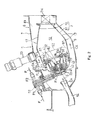
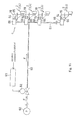
- Fig. 1 shows a head portion of a combustor 1 of a gas turbine engine including a fuel supply device according to Embodiment 1 of the present invention.
- the combustor 1 is configured to combust an air-fuel mixture generated by mixing fuel with compressed air supplied from a compressor (not shown) in the gas turbine engine, and feed high-temperature and high-pressure combustion gas generated by the combustion to a turbine to drive the turbine.
- the combustor 1 is of an annular type and has a configuration in which a tubular inner casing 8 is disposed inward relative to a tubular outer casing 7 such that the center axis C of the gas turbine engine is a center of the inner casing 8.
- the outer casing 7 and the inner casing 8 constitute a combustor housing 6 having an annular inner space.
- a tubular inner liner 11 is disposed inward relative to a tubular outer liner 10.
- These liners 11 and 10 constitute a combustion tube 9.
- the combustion tube 9 is disposed concentrically with the combustor housing 6.
- the combustion tube 9 has an annular combustion chamber 12 inside thereof.
- a plurality of (14 in the present embodiment) fuel injection units 2 for injecting fuel to an interior of the combustion chamber 12 are attached to a top wall 9a of the combustion tube 9.
- the fuel injection units 2 are arranged at equal intervals on a circle which is concentric with the combustion tube 9.
- Each of the fuel injection units 2 includes a pilot burner 3 and a main burner 4.
- the main burner 4 is provided to enclose the outer periphery of the pilot burner 3 such that the main burner 4 is concentric with the pilot burner 3.
- the pilot burner 3 is a burner for diffusion combustion, while the main burner 4 is a burner for lean pre-mixed combustion. A detail of these burners will be described later.
- Two ignition plugs 13 for performing ignition extend in a radial direction of the combustion tube 9 to penetrate the outer casing 7 and the outer liner 10, and their tip ends face the fuel injection units 2, respectively.
- a combustible air-fuel mixture injected from each of the two fuel injection units 2 facing the two ignition plugs 13, respectively is ignited, and then a flame generated by the combustion is transferred to a combustible air-fuel mixture injected from an adjacent fuel injection unit 2, and further to a combustible air-fuel mixture injected from an adjacent fuel injection unit 2. Finally, the flame spreads to the entire periphery.
- Fig. 2 is an enlarged cross-sectional view taken along line II-II of Fig. 1 .
- Compressed air CA supplied from the compressor is introduced into the annular inner space of the combustor housing 6 via an annular pre-diffuser passage 14.
- the introduced compressed air CA is supplied to the fuel injection units 2, and to the interior of the combustion chamber 12 through a plurality of air introduction ports 17 provided on each of the outer liner 10 and the inner liner 11 of the combustion tube 9.
- Fuel pipe units 18 mounted to the outer casing 7 are coupled to a base portion 19 of the combustion tube 9.
- the fuel pipe units 18 constitute first fuel supply systems F1 for supplying fuel for diffusion combustion to the pilot burners 3 and second fuel supply systems F2 for supplying fuel for lean pre-mixed combustion to the main burners 4.
- Each of the fuel injection units 2 is mounted to the outer liner 10 via a flange 5A provided at its outer periphery and a support 5B provided at the outer liner 10.
- the outer liner 10 is mounted to the outer casing 7 by a liner fastening pin P.
- a first-stage nozzle NT of the turbine is coupled to a downstream end portion of the combustion tube 9.
- Each of the pilot burners 3 is provided at a center portion of the corresponding fuel injection unit 2.
- the pilot burner 3 includes a fuel nozzle 31, a diffusion nozzle 32, and inside and outside swirlers 33.
- Fuel F for diffusion combustion from the first fuel supply system F1 is injected from the fuel nozzle 31.
- the fuel F injected from the fuel nozzle 31 is atomized by the compressed air CA which has passed through the swirlers 33, and then is sprayed into the combustion chamber 12 through the diffusion nozzle 32, thereby forming a diffusion combustion zone 50.
- the main burner 4 of an annular shape is provided to enclose the outer periphery of the pilot burner 3.
- the main burner 4 includes fuel nozzles 41 arranged at circumferentially equal intervals, a pre-mixed passage 42, and inside and outside swirlers 43.
- Fuel F for pre-mixed combustion supplied from the second fuel supply system F2 is injected from the fuel nozzles 41 into the pre-mixed passage 42.
- the fuel F for pre-mixed combustion injected into the pre-mixed passage 42 is mixed with the compressed air CA which has passed through the swirlers 43, and results in a pre-mixed air-fuel mixture.
- the pre-mixed air-fuel mixture is injected into the combustion chamber 12, thereby forming a pre-mixed combustion zone 51.
- the pilot burner 3 is supplied with the fuel F from the first fuel supply system F1 in all load zones.
- the main burner 4 is supplied with the fuel F from the second fuel supply system F2 in a high load zone (high fuel pressure zone) and a medium load zone (medium fuel pressure zone).
- the high load zone is a load zone which is not less than, for example, 70% of a maximum load.
- the medium-load zone is between the high load zone and the low load zone (low fuel pressure zone), and is a load zone which is, for example, 40 ⁇ 70% of the maximum load.
- the main burner 4 is not supplied with the fuel F in the low load zone which is a load zone which is not more than, for example, 40% of the maximum load. Therefore, in this load zone, only the compressed air CA is supplied to the main burner 4 and to the combustion chamber 12.
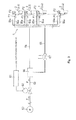
- a common pilot fuel passage 64 and a common main fuel passage 65 are connected to the fuel injection units 2 of the combustor 1.
- the upstream end of the pilot fuel passage 64 and the upstream end of the main fuel passage 65 are connected to a collecting fuel passage 63.
- the collecting fuel passage 63 is provided with a fuel pump 60 and a total flow control valve 62.
- the total flow control valve 62 is controlled by a fuel controller 61.
- the fuel pump 60 is actuated to feed the fuel F to the interior of the collecting fuel passage 63.
- the fuel controller 61 receives an output command signal by, for example, an operation of a throttle lever provided outside.
- the fuel controller 61 sets an opening degree of the total flow control valve 62.
- the opening degree of the total flow control valve 62 properly, the fuel is supplied to the entire combustor 1 with a required amount via the collecting fuel passage 63, the pilot fuel passage 64, and the main fuel passage 65.
- a fuel divider 66 is provided at a branch portion at which the collecting fuel passage 63 branches into the pilot fuel passage 64 and the main fuel passage 65.
- the pilot fuel passage 64 branches into plural passages (14 passages).
- the branch passages 64a communicate with the pilot burners 3 via the first fuel supply systems F1 of the corresponding fuel injection units 2, respectively.
- the main fuel passage 65 branches into plural passages (14 passages).
- the branch passages 65a communicate with the main burners 4 via the second fuel supply systems F2 of the corresponding fuel injection units 2, respectively.
- the main fuel passage 65 is provided with a cut-off valve 67 which closes the main fuel passage 65 under an engine load state which is not more than a certain load, i.e., in the low load zone including starting of the gas turbine engine. In this configuration, in the low load zone, the main fuel passage 65 is closed more surely, and only the diffusion combustion is conducted by the pilot burners 3. As a result, stability of combustion including ignition performance and flame stabilizing performance can be ensured.
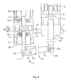
- Fig. 4 is a longitudinal sectional view of the fuel divider 66.
- the fuel divider 66 of the present embodiment is of a cylinder type, and includes a drive cylinder 71, a movable member 72, a valve element cylinder 91, a first valve block 92, a second valve block 93, and a coupling mechanism 110.
- a drive cylinder 71 As shown in Fig. 4 , the fuel divider 66 of the present embodiment is of a cylinder type, and includes a drive cylinder 71, a movable member 72, a valve element cylinder 91, a first valve block 92, a second valve block 93, and a coupling mechanism 110.
- these components will be described sequentially.
- the drive cylinder 71 is configured to house the movable member 72 as described later.
- a top portion of a hollow portion 74 of the drive cylinder 71 is provided with a female thread.
- a spring adjusting member 80 which also serves as a lid member is threaded into the female thread.
- a spring chamber 82 is formed between the spring adjusting member 80 and the movable member 72.
- a coil-shaped compressive spring member 73 is inserted into the spring chamber 82.
- the spring member 73 applies a force to the movable member 72 in a downward direction in Fig. 4 .
- An initial strain amount, i.e., a spring force of the spring member 73 is adjusted by changing an amount up to which the spring adjusting member 80 is threaded into the drive cylinder 71.
- the spring adjusting member 80 is provided with a plurality of communication holes 83 extending in a direction of a center axis C1 of the drive cylinder 71. Through the communication holes 83, the spring chamber 82 communicates with outside.
- a fuel entrance (inlet) E1 is provided on the side portion of the drive cylinder 71 to extend in a radial direction X. The fuel entrance E1 communicates with the downstream end portion of the collecting fuel passage 63 (see Fig. 3 ), and opens in a drive chamber 84 formed under the bottom surface of the piston 78.
- the movable member 72 is movable in the direction of the center axis C1 inside the drive cylinder 71.
- the movable member 72 includes the piston 78 slidably inserted into the hollow portion 74, and a connecting rod 79 coupled to the piston 78 and extending axially downward.
- the connecting rod 79 is inserted into the piston 78, and its tip end portion (upper end portion) protrudes into the spring chamber 82.
- the connecting rod 79 has a male thread at a tip end portion thereof.
- a flanged nut N and a spring receiver seat 81 are threaded into the tip end portion in this order.
- the valve element cylinder 91 is configured to house a valve element 97 therein.
- the valve element cylinder 91 and the drive cylinder 71 are formed unitarily to construct a housing unit H.
- a first valve block 92 and a second valve block 93 as described later are attached to the inner surface of the valve element cylinder 91 such that the first valve block 92 and the second valve block 93 are axially spaced apart from each other.
- a valve chamber 94 is formed between the first valve block 92 and the second valve block 93.
- the first valve block 92 is provided with a communication passage E4 extending in the radial direction X. Through the communication passage E4, the valve chamber 94 and the drive chamber 84 of the drive cylinder 71 communicate with each other. Since the fuel entrance E1 communicates with the drive chamber 84 of the drive cylinder 71 as described above, the fuel entrance E1, the drive chamber 84, and the valve chamber 94 communicate with one another through the communication passage E4.
- the first valve block 92 is located at the other end side (lower side in Fig. 4 ) of the valve element cylinder 91.
- the first valve block 92 has a linear through-hole 95 axially extending.
- a bottom plate 103 is fastened to the bottom portion of the first valve block 92 by a bolt B reaching the valve element cylinder 91.
- a seal ring OR is mounted between the first valve block 92 and the bottom plate 103, in the vicinity of the through-hole 95. The seal ring OR prevents the fuel F from leaking through the through-hole 95.
- a valve seat 104 on which a pilot port needle valve element 101 is seated is attached to the end portion of the first valve block 92 at the valve chamber 94 side. The interior of the valve seat 104 defines the pilot port 76.
- the valve seat 104 is fastened to the first valve block 92 by a hexagon cap nut 108.
- the valve seat 104 is constituted by a seal washer made of a material having higher elasticity than the valve element 101 made of steel, for example, resin or rubber.
- the first valve block 92 is provided with a pilot exit (outlet) E2 penetrating a peripheral wall thereof in the radial direction X.
- the through-hole 95 of the first valve block 92 communicates with the pilot fuel passage 64 (see Fig. 3 ) via the pilot exit E2.
- the second valve block 93 is located at one end side (upper side in Fig. 4 ) of the valve element cylinder 91.
- the second valve block 93 has a linear through-hole 96 extending axially.
- the valve element cylinder 91 has a female thread at one end portion of an inner peripheral surface thereof.
- the second valve block 93 is threaded into the female thread.
- the through-hole 96 of the second valve block 93 constitutes a main exit E3, and communicates with the main fuel passage 65 (see Fig. 3 ).
- a valve seat 105 is attached to the end portion of the second valve block 93 at the valve chamber 94 side. The center portion of the valve seat 105 defines the main port 77.
- the valve seat 105 is fastened to the second valve block 93 by a hexagon cap nut 108.
- the valve seat 105 is constituted by a seal washer made of a material having higher elasticity than the valve element 102 made of steel, for example, resin or rubber.
- the valve seat 105 is pressed by the main port needle valve element 102 and is elastically deformed, thereby causing the main port 77 to be closed.
- the valve element 97 is a member movable in a direction of a center axis C2 inside the valve element cylinder 91.
- the valve element 97 is made of steel, and is a dual needle valve having a longitudinal section of a substantially cross-shape.
- the valve element 97 includes a body 98, the pilot port needle valve element 101 and the main port needle valve element 102.
- the body 98 has a disc-shape, and is placed in the interior of the valve chamber 94.
- the body 98 has a plurality of communication holes 98a axially penetrating therethrough such that the communication holes 98a are arranged at circumferentially equal intervals.
- the pilot port needle valve element 101 is positioned at one side in the axial direction of the body 98, and extends axially to have a taper shape in which a thickness decreases gradually from a base end at the body 98 side toward a tip end (in a downward direction in Fig. 4 ).
- the main port needle valve element 102 is positioned at one side in the axial direction of the body 98, and extends axially to have a taper shape in which a thickness decreases gradually from a base end at the body 98 side toward a tip end (in an upward direction in Fig. 4 ).
- the pilot port needle valve element 101 is provided integrally with a valve actuating rod 99 at a tip end portion thereof.
- the pilot port needle valve element 101 is configured to adjust the opening degree of the pilot port 76, and need not fully close the pilot port 76. Therefore, the valve seat 104 need not be made of a material having high elasticity.
- the coupling mechanism 110 couples the valve actuating rod 99 of the valve element 97 to the connecting rod 79 of the movable member 72.
- the coupling mechanism 110 is mainly composed of a mount plate 114 mounted to the bottom surface of the bottom plate 103, and a coupling member 121 which is an elongated rod shape.
- the mount plate 114 is provided with a cylindrical pivot 115 protruding in a direction Z perpendicular to the drawing sheet.
- the coupling member 121 has oval engagement holes 118 and 119 at both ends.
- the coupling member 121 has a circular fitting hole 120 in a portion between the engagement holes 118 and 119 in a location closer to the engagement hole 119.
- An engagement pin 116 provided at the lower portion of the connecting rod 79 to protrude in Z-direction is inserted into the engagement hole 118 of the coupling member 121.
- An engagement pin 117 provided at the lower portion of the valve actuating rod 99 to protrude in Z-direction is inserted into the engagement hole 119 of the coupling member 121.
- the pivot 115 is pivotally inserted into the fitting hole 120 of the coupling member 121. This allows the coupling member 121 to be pivoted around the pivot 115 according to the axial movement of the connecting rod 79 and the valve actuating rod 99.
- the coupling mechanism 110, the drive cylinder 71, and the movable member 72 (piston 78 and connecting rod 79) constitute a drive element 100.
- Fig. 5 is enlarged view of a portion of Fig. 4 , showing an open state of the pilot port 76.
- Fig. 6 is an enlarged view of a portion of Fig. 4 , showing an open state of the main port 77.
- the pilot port 76 and the main port 77 gradually and smoothly transition to the open state or to the closed state, according to the fuel pressure. Because of this, the amount of the fuel fed to the pilot fuel passage 64 and the amount of the fuel fed to the main fuel passage 65 in each fuel pressure zone can be adjusted smoothly.
- the position of the pivot 115 By adjusting the position of the pivot 115, the amount of movement of the valve element 97 (pilot port needle valve element 101 and main port needle valve element 102) actuated according to the fuel pressure can be adjusted. Specifically, if the position of the pivot 115 is changed to the right in Fig.
- the amount of movement of the valve element 97 with respect to the fuel pressure increases, while if the position of the pivot 115 is changed to the left in Fig. 4 , the amount of movement of the valve element 97 decreases.
- a horizontal axis indicates a pressure difference (hereinafter referred to as "fuel pressure difference") between the pressure at the fuel entrance E1 and the pressure in the combustion chamber 12 (equal to the pressure at the exit EX of the pilot burner 3), and a vertical axis indicates the flow rate of the fuel F.
- the fuel pressure difference corresponds to an engine load.
- a curve line indicated by a bold line indicates a flow rate (hereinafter referred to as "total flow rate") which is a sum of the flow rate of the fuel flowing through the pilot fuel passage 64 and the flow rate of the fuel flowing through the main fuel passage 65.
- total flow rate a flow rate which is a sum of the flow rate of the fuel flowing through the pilot fuel passage 64 and the flow rate of the fuel flowing through the main fuel passage 65.
- the low fuel pressure zone Z1 includes a predetermined 30% MTO (Max Take Off).
- the piston 78 inside the drive cylinder 71 of Fig. 4 starts to move up against the spring force applied by the spring member 73 from a location before the fuel pressure difference reaches P1 in Fig. 7 .
- the coupling mechanism 110 causes the valve actuating rod 99 to move downward, and the valve element 97 starts to move down.
- the pilot port 76 starts to be closed, and the main port 77 starts to be opened as shown in Fig. 6 , so that the fuel pressure difference falls into a medium fuel pressure zone Z2 in Fig. 7 .
- the pilot port 76 starts to be closed gradually, and the flow rate of the fuel in the pilot fuel passage 64 decreases as the fuel pressure difference increases as indicated by a curve A1.
- the pilot port 76 is a little open.
- the main port 77 of Fig. 4 is opened gradually. Thereby, the flow rate of the fuel flowing through the main fuel passage 65 increases gradually as indicated by a curve B of Fig. 7 .
- the main port 77 is opened to its maximum opening degree. In this way, a most part of the fuel F is supplied to the main fuel passage 65, and the remaining part of the fuel F is supplied to the pilot fuel passage 64.
- the fuel injection units 2 are supplied with the fuel F from both of the pilot fuel passage 64 and the main fuel passage 65, and the pilot burner 3 and the main burner 4 are both activated.
- a total flow rate indicated by a curve C in the medium fuel pressure zone Z2 in Fig. 7 is set by the total flow control valve 62.
- the fuel is supplied to the pilot fuel passage 64 of Fig. 4 in such a manner that the pilot port 76 is closed gradually. This makes it possible to smoothly reduce the flow rate of the fuel flowing through the pilot fuel passage 64.
- the flow rate of the fuel flowing through the pilot fuel passage 64 increases with the fuel pressure difference such that this flow rate is suppressed to about 10% of the total flow rate, while the flow rate of the fuel flowing through the main fuel passage 65 increases such that this flow rate is maintained at about 90% of the total flow rate as indicated by the curve B1.
- the high fuel pressure zone Z3 includes a predetermined 85%MTO. In this way, in the high fuel pressure zone Z3, the main burner 4 primarily performs the pre-mixed combustion while achieving reduced NO x and the pilot burner 3 secondarily performs diffusion combustion, thereby ensuring combustion stability.
- the fuel divider 66 provided at the branch portion at which the collecting fuel passage 63 branches into the pilot fuel passage 64 and the main fuel passage 65, as shown in Fig. 3 , the amount of the fuel fed to the pilot fuel passage 64 and the amount of the fuel fed to the main fuel passage 65 are adjusted automatically according to the fuel pressure, i.e., the engine load.
- the diffusion combustion and the pre-mixed combustion can be carried out appropriately in the combustor 1. Since it is not necessary to provide the flow control valve in each of the pilot fuel passage 64 and the main fuel passage 65, the structure is simplified, and a complicated control circuit may be dispensed with, which results in cost saving.
- the pilot port 76 and the main port 77 gradually transition to the open state or to the closed state, according to the fuel pressure, the amount of the fuel fed to the pilot fuel passage 64 and the amount of the fuel fed to the main fuel passage 65 can be adjusted smoothly according to each fuel pressure. Furthermore, since the main port 77 is closed by moving the main port needle valve element 102, the main port 77 has high sealing performance, and thus, the fuel can be sealed surely.
- the pilot port needle valve element 101 and the main port needle valve element 102 constituting the valve element 97 are positioned on axial one end surface and an axial opposite end surface of the body 98 slidable inside the valve element cylinder 91, and are provided integrally with the body 98. Because of this, the structure of the valve element 97 can be simplified, and the size of the entire fuel divider 66 can be reduced.
- a fuel supply device of Embodiment 2 of the present invention will be described with reference to Figs. 8 to 10 .
- the fuel supply device of the present embodiment is basically identical in configuration to the fuel supply device of Embodiment 1, except for the configuration of the fuel divider. Therefore, hereinafter, a fuel divider 66A of the present embodiment will be described in a larger part.
- Fig. 8 is a longitudinal sectional view showing the fuel divider 66A of Embodiment 2.
- the fuel divider 66A of the present embodiment includes a housing unit 201, a drive element 203, a pilot port needle valve element 211, and a main port needle valve element 212. These components will be described sequentially.
- the housing unit 201 is a member for housing the drive element 203 therein. As shown in Fig. 8 , the housing unit 201 is provided on a top portion thereof with a fuel entrance (inlet) 75 communicating with the downstream portion of the collecting fuel passage 63, and on side portions thereof, the pilot port 76 and the main port 77. A disc-shaped spring adjustment member 215 is mounted to a bottom opening of the housing unit 201. A coil-shaped compressive adjustment spring member 216 is interposed between the spring adjusting member 215 and the drive element 203. The compressive adjustment spring member 216 applies a force to the drive element 203 in an upward direction in Fig. 8 .
- An initial strain amount of the spring of the compressive adjustment spring member 216 is adjusted by changing the axial position of the spring adjusting member 215.
- a stopper 217 is attached to the upper surface of the spring adjusting member 215 to protrude axially upward. The stopper 217 restricts the down position of the drive element 203.
- Protruding wall portions 224 and 225 are provided on the peripheral wall of the housing unit 201 to face each other with respect to a center axis C3 between them.
- the protruding wall portions 224 and 225 protrude outward in the radial direction X.
- Bosses 226 and 227 are provided to protrude inward in the radial direction X.
- Seal pipes 208 and 209 are secured to the inside of the protruding wall portion 224 and to the inside of the protruding wall portion 225, respectively.
- Valve seats 213 and 214 on which the needle valve elements 211 and 212 (described later) are to be seated are provided on inner end portions (inlet end portions) of the seal pipes 208 and 209, respectively.
- the seal pipes 208 and 209 are made of rubber or resin having higher elasticity than the metal-made needle valve elements 211 and 212.
- the downstream portion of the seal pipe 208 communicates with the pilot fuel passage 64, while the downstream portion of the seal pipe 209 communicates with the main fuel passage 65.
- the upstream end portion of the seal pipe 208 constitutes the pilot port 76, while the upstream end portion of the seal pipe 209 constitutes the main port 77.
- a rotation inhibiting mechanism 235 is provided at the upper portion of the housing unit 201.
- the rotation inhibiting mechanism 235 includes a guide section 237 and a guide member 238.
- the guide section 237 is joined to the upper surface of a drive portion 205 (described later) by welding or is integrated with the drive portion 205.
- the guide section 237 is provided with a plurality of through-holes 236 extending in the direction of the center axis C3.
- the guide member 238 is attached to the inner peripheral surface of the housing unit 201, and is configured to guide the guide section 237 (i.e., drive element 203) such that the guide section 237 is inhibited from moving circumferentially with respect to the housing unit 201 and is slidable in the direction of the center axis C3.
- the rotation inhibiting mechanism 235 allows a pilot cam surface 206 and a cam follower 223 of the pilot port needle valve element 211 to face each other accurately, and a main cam surface 207 and a cam follower 223 of the main port needle valve element 212 to face each other accurately.
- the drive element 203 is a member housed in the housing unit 201, and being movable in the direction (axial direction) of the center axis C3. As shown in Figs. 8 and 9 , the drive element 203 includes a large-diameter disc-shaped pressure receiving bottom plate 204 provided at a base end portion (lower end portion) to receive the fuel pressure, the small-diameter cylindrical drive portion 205 extending axially upward and continuously with the pressure receiving bottom plate 204, and a large-diameter disc-shaped guide portion 237 secured to or integrated with the top portion of the drive portion 205.
- the drive portion 205 has the pilot cam surface 206 on one side thereof, and the main cam surface 207 on the other side thereof which is opposite to the one side.
- the drive portion 205 of the drive element 203 has the pilot cam surface 206 defined by a groove portion G1 extending axially on a right side surface thereof, and the main cam surface 207 defined by a groove portion G2 extending axially on a left side surface thereof.
- the pilot cam surface 206 has an inclined surface S1 gradually receding inward in the radial direction X from a base end toward a tip end (in an upward direction).
- the main cam surface 207 has an inclined surface S2 extending to an advanced position gradually inward in the radial direction X from the base end toward the tip end (in the upward direction).
- the pilot port needle valve element 211 and the main port needle valve element 212 are members movable according to the axial movement of the drive element 20.
- the drive element 203 moves axially according to the fuel pressure at the fuel entrance 75, thereby allowing the pilot port needle valve element 211 to be driven by the pilot cam surface 206 and the main port needle valve element 212 to be driven by the main cam surface 207.
- the needle valve elements 211 and 212 are positioned to face each other with respect to the center axis C3 between them.
- the needle valve elements 211 and 212 are unable to move in the direction of the center axis C3, and are able to move in the radial direction X.
- Each of the needle valve elements 211 and 212 includes a disc-shaped flange 221 in which the radial direction X is a valve element center axis C4, a valve element portion 222 located outward relative to the flange 221 in the direction of the center axis C4, and the cam follower 223 located inward relative to the flange 221 in the direction of the center axis C4.
- the valve element portion 222 has a conical shape having an outer diameter decreasing in an outward direction of the direction of the center axis C4.
- the cam follower 223 extends in a direction opposite to the direction in which the valve element portion 222 extends and is movable on each of the cam surfaces 206 and 207.
- annular recess 228 between the protruding wall portion 224 and the boss 226 in the side portion of a cylinder bore 202, and an annular recess 229 between the protruding wall portion 225 and the boss 227 in the side portion of the cylinder bore 202.
- an opening spring member 218 constituted by a coil spring is inserted, while between the annular recess 229 and the flange (spring receiver seat) 221 of the needle valve element 212, an opening spring member 219 constituted by a coil spring is inserted.
- the valve element 211 is applied with a force from the opening spring member 218 to be away from the valve seat 213, while the valve element 212 is applied with a force from the opening spring member 219 to be away from the valve seat 214.
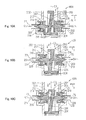
- Fig. 10A shows a state where only the pilot port 76 is opened
- Fig. 10B shows a state where the pilot port 76 and the main port 77 are a little opened
- Fig. 10C shows a state where the main port 77 is opened to a greater degree.
- a low fuel pressure zone (Z1 in Fig. 7 ) in which the fuel pressure at the fuel entrance 75 (see Fig. 8 ) is low, as shown in Fig. 10A , the spring force applied by the adjustment spring member 216 is greater than the pressure applied from the fuel F to the pressure receiving bottom plate 204, thereby causing the drive element 203 to move up.
- the pilot port needle valve element 211 contacts the lower portion of the pilot cam surface 206, and therefore recedes inward in the radial direction X.
- the pilot port needle valve element 211 moves away from the valve seat 213, and opens the pilot port 76 gradually.
- the main port needle valve element 212 contacts the lower portion of the main cam surface 207, and moves to an advanced position in the outward direction of the radial direction X. Thereafter, the main port needle valve element 212 is pressed against the valve seat 214, and closes the main port 77. In this way, the main port 77 is pressed by the main port needle valve element 212 and is thereby closed. Therefore, the main port 77 provides high sealing performance when the main port 77 is closed.
- the pressure receiving bottom plate 204 is pressed down due to the pressure of the fuel F, thereby causing the drive element 203 to move down.
- the pilot port needle valve element 211 is pressed by the pilot cam surface 206 and moves gradually to an advanced position in the outward direction of the radial direction X.
- the pilot port needle valve element 211 moves closer to the valve seat 213 and decreases the opening degree of the pilot port 76.
- the main port needle valve element 212 recedes inward in the radial direction X gradually according to the main cam surface 207. As a result, the main port needle valve element 212 moves away from the valve seat 214, and opens the main port 77.
- a high fuel pressure zone (Z3 in Fig. 7 ) in which the fuel pressure further increases, as shown in Fig. 10C , the drive element 203 further moves down, and the pilot port needle valve element 211 moves gradually to an advanced position in the outward direction of the radial direction X.
- the open state of the pilot port 76 is maintained in a state where its opening degree is smaller.
- the main port needle valve element 212 recedes gradually inward in the radial direction X.
- the main port needle valve element 212 moves to a greater degree away from the valve seat 214, and opens the main port 77 to a greater degree.
- the fuel divider 66A of the present embodiment is simply configured in such a manner that the drive element 203 moves inside the housing unit 201. Therefore, the fuel divider 66A can be implemented with a simple structure and inexpensively, and can seal the fuel surely.
- Fig. 11 is a view showing a fuel control system according to Embodiment 3 of the present invention.
- the collecting fuel passage 63 is extended up to the fuel injection units 2, and the fuel divider 66 is provided for each of the fuel injection units 2 in a one-to-one correspondence.
- the pilot fuel passage 64 and the main fuel passage 65 are provided independently for each of the fuel injection units 2.
- the fuel divider 66 is built into, for example, the fuel pipe unit 18 of each of the fuel injection units 2. In this configuration, the single collecting fuel passage 63 with a great cross-section is sufficient to reach each of the fuel injection units 2.
- Embodiment 3 makes it easier to perform a piping work for laying out the fuel passage to the fuel injection units 2 as compared to the configuration in which two fuel passages, i.e., the pilot fuel passage 64 and the main fuel passage 65 are used, like Embodiment 1.
- the other operation and advantage of Embodiment 3 are similar to those of Embodiment 1.
- the fuel divider 66 shown in Fig. 11 is the fuel divider 66 described in Embodiment 1, it may be replaced by the fuel divider 66A of Embodiment 2 shown in Fig. 8 .
- the fuel spraying type of the pilot burner is of an air blast type
- the present invention is not limited to this, but the fuel spraying type may be of, for example, a pressure spraying type.
- the main burner is of the pre-mixed combustion type, it may be of, for example, a diffusion combustion type.
Abstract
Description
- The present invention relates to a fuel supply device of a gas turbine engine for supplying a fuel to a combustor including pilot burners and main burners.
- For environment protection purposes, in gas turbine engines, strict environmental standards are set in a composition of combustion exhaust gas emitted. It is required to reduce harmful substances such as nitrogen oxide (hereinafter expressed as NOx) from the exhaust gas. In large-sized gas turbines and engines for aircraft, a pressure ratio tends to be set high, because of requirement of low fuel consumption and a high power output. Correspondingly, air at an inlet of a fuel supply device tends to be placed in higher temperature and higher pressure conditions. With an increase in the temperature of the air at the inlet of the fuel supply device, a combustion temperature rises, which may undesirably result in an increase in the amount of NOx in the exhaust gas.
- Under the circumstances, in recent years, there has been proposed a combined combustion method in which two combustion methods, i.e., a lean pre-mixed combustion method which can reduce the amount of Nox generation effectively, and a diffusion combustion method which has high ignition performance and high flame stabilizing performance are combined. In the lean pre-mixed combustion method, air and fuel are pre-mixed and an air-fuel mixture with a uniform fuel concentration is combusted. In this method, a combustion zone in which a flame temperature is locally high does not exist. In addition, the flame temperature can be lowered as a whole because of lean fuel. Therefore, the lean pre-mixed combustion method has an advantage that the amount of NOx generation can be reduced effectively. However, in the lean pre-mixed combustion method, since a great amount of air and fuel are mixed uniformly, a local combustion concentration in a combustion zone is very low, which degrades combustion stability particularly under a low load state. By comparison, in the diffusion combustion method, the fuel and the air are combusted while diffusing and mixing them. This method has advantages that a flame is less likely to vanish even during the low load state, and the flame stabilizing performance is high. Therefore, in the combined combustion method which is a combination of the lean pre-mixed combustion method and the diffusion combustion method, combustion stability in a diffusion combustion zone can be maintained during starting or during the low load state, and the amount of NOx generation in a lean pre-mixed combustion zone can be reduced during a high load state.
- A fuel supply device according to the combined combustion method includes pilot burners which inject fuel spray so as to form the diffusion combustion zone within a combustion chamber by the diffusion combustion method, and main burners which supply an air-fuel mixture containing pre-mixed fuel and air so as to form a pre-mixed combustion zone within the combustion chamber by the lean pre-mixed combustion method. In this fuel supply device, fuel is supplied only to the pilot burners during starting or during the low load state, while the fuel is also supplied to the main burners in addition to the pilot burners during the high load state. When the gas turbine engine transitions from the low load state to the high load state, the fuel supply device controls a ratio between the fuel supplied to the pilot burners and the fuel supplied to the main burners so that the ratio changes gradually from 1:0 to, for example, 1: 9, while maintaining a proper value of the ratio for achievement of stable combustion and reduction of NOx.
- In a conventional method, to perform the above complicated control, flow control valves are respectively provided in a pilot fuel passage through which the fuel is supplied to the pilot burners and a main fuel passage through which the fuel is supplied to the main burners, and a controller controls these flow control valves (Patent Literature 1).
- However, if the flow control valves are provided in these two fuel passages, respectively, a ratio of the weight and cost of the flow control valves and the controller with respect to weight and cost of an overall engine increases especially in a small-sized gas turbine for aircraft, and its influence is non-negligible, although the ratio is differed between a gas turbine for aircraft and a gas turbine for industry, or between a large-sized gas turbine and a small-sized gas turbine, which results in an influence which cannot be ignored. This precludes application of a combined combustion method which requires an additional fuel control system (flow control valves and controller) to the small-sized gas turbine for aircraft. Further, the addition of the fuel control system causes an increased weight and a complicated structure.
- Under the circumstances, the applicant proposed a system in which a fuel divider is provided between a pilot fuel passage through which the fuel is supplied to the pilot burners and a main fuel passage through which the fuel is supplied to the main burners, and a collecting fuel passage through which the fuel is supplied to the pilot fuel passage and to the main fuel passage, and a controller controls the fuel divider and the fuel passages (Patent Literature 2).
-
- Patent Literature 1: Japanese Laid-Open Patent Application Publication No.
Hei. 5-52124 - Patent Literature 2: Japanese Patent No.
4220558 - In the system using the above stated fuel divider, the fuel is divided to be fed to the pilot fuel passage and to the main fuel passage so that the fuel is fed to the pilot burners and to the main burners. It is necessary to ensure compatibility between the fact that the fuel is divided smoothly and accurately and the fact that the fuel divider ensures fuel sealing performance. However, it is difficult to ensure the sealing performance in the fuel divider.
- An object of the present invention is to provide a fuel supply device of a gas turbine engine which can perform fuel flow control with a simple structure and inexpensively and ensure sufficient fuel sealing performance, in a combined combustion method in which two combustion methods which are a diffusion combustion method and a lean pre-mixed combustion method are combined.
- To achieve the above object, there is provided a fuel supply device of a gas turbine engine, of the present invention, which supplies fuel to a combustor including a pilot burner and a main burner; the fuel supply device comprising: a pilot fuel passage through which the fuel is supplied to the pilot burner; a main fuel passage through which the fuel is supplied to the main burner; a collecting fuel passage through which the fuel is supplied to the pilot fuel passage and to the main fuel passage; and a fuel divider which divides the fuel supplied from the collecting fuel passage to feed the fuel to the pilot fuel passage and to the main fuel passage; wherein the fuel divider includes: a fuel entrance into which the fuel supplied from the collecting fuel passage is introduced; a pilot port connected to the pilot fuel passage; a main port connected to the main fuel passage; a pilot port needle valve element which adjusts an opening degree of the pilot port; a main port needle valve element which opens and closes the main port; and a drive element which is actuated according to the fuel pressure at the fuel entrance to move the pilot port needle valve element and the main port needle valve element; wherein when the fuel pressure at the fuel entrance is not higher than a predetermined value, the fuel is supplied only to the pilot fuel passage; and when the fuel pressure at the fuel entrance is higher than the predetermined value, the fuel is supplied to the pilot fuel passage and to the main fuel passage.
- In accordance with this configuration, by using the fuel divider, the amount of the fuel fed to the pilot fuel passage and the amount of the fuel fed to the main fuel passage are adjusted automatically according to the fuel pressure. This eliminates a need for flow control valves in the pilot fuel passage and in the main fuel passage, respectively. Therefore, a structure is simplified, and a complicated control circuit may be dispensed with, which results in manufacturing cost saving. In addition, since the main port is closed by actuating the drive element so as to move the main port needle valve element, it provides high sealing function, and is able to seal the fuel surely.
- A fuel supply device of a gas turbine engine of the present invention has a simple and inexpensive structure, and can ensure sufficient fuel sealing performance.
-
- [
Fig. 1] Fig. 1 is a schematic front view showing a fuel supply device of a gas turbine engine according toEmbodiment 1 of the present invention. - [
Fig. 2] Fig. 2 is an enlarged longitudinal-sectional view taken along line II-II ofFig. 1 . - [
Fig. 3] Fig. 3 is a view showing a fuel control system. - [
Fig. 4] Fig. 4 is a longitudinal-sectional view showing a fuel divider. - [
Fig. 5] Fig. 5 is a partially enlarged view showing major components of the fuel divider ofFig. 4 . - [
Fig. 6] Fig. 6 is a partially enlarged view showing major components of the fuel divider ofFig. 4 . - [
Fig. 7] Fig. 7 is a curve showing a flow (flow rate) change according to a fuel pressure change in the fuel divider. - [
Fig. 8] Fig. 8 is a longitudinal sectionalview showing Embodiment 2 of the present invention. - [
Fig. 9] Fig. 9 is a perspective view showing major components of the fuel divider ofFig. 8 . - [
Fig. 10] Fig. 10A is a longitudinal sectional view showing an open state of a pilot port of the fuel divider,Fig. 10B is a longitudinal sectional view showing a transition state of the pilot port and a transition state of a main port, andFig. 10C is a longitudinal sectional view showing an open state of the main port. - [
Fig. 11] Fig. 11 is a view showing a fuel control system according toEmbodiment 3 of the present invention. - [
Fig. 12] Fig. 12 is an enlarged side view of major components of a fuel injection unit ofFig. 11 . - Hereinafter, preferred embodiments of the present invention will be described with reference to the drawings.
- First of all,
Embodiment 1 of the present invention will be described with reference toFigs. 1 to 7 . Hereinafter, description will be given sequentially of the configuration of a combustor, the configuration of a fuel control system, the configuration of a fuel divider, the operation of the fuel divider, and the relation between a fuel pressure and a flow (flow rate) of the fuel. -
Fig. 1 shows a head portion of acombustor 1 of a gas turbine engine including a fuel supply device according toEmbodiment 1 of the present invention. Thecombustor 1 is configured to combust an air-fuel mixture generated by mixing fuel with compressed air supplied from a compressor (not shown) in the gas turbine engine, and feed high-temperature and high-pressure combustion gas generated by the combustion to a turbine to drive the turbine. - The
combustor 1 is of an annular type and has a configuration in which a tubular inner casing 8 is disposed inward relative to a tubularouter casing 7 such that the center axis C of the gas turbine engine is a center of the inner casing 8. Theouter casing 7 and the inner casing 8 constitute acombustor housing 6 having an annular inner space. In the annular inner space of thecombustor housing 6, a tubularinner liner 11 is disposed inward relative to a tubularouter liner 10. Theseliners combustion tube 9. Thecombustion tube 9 is disposed concentrically with thecombustor housing 6. Thecombustion tube 9 has anannular combustion chamber 12 inside thereof. A plurality of (14 in the present embodiment)fuel injection units 2 for injecting fuel to an interior of thecombustion chamber 12 are attached to atop wall 9a of thecombustion tube 9. Thefuel injection units 2 are arranged at equal intervals on a circle which is concentric with thecombustion tube 9. Each of thefuel injection units 2 includes apilot burner 3 and amain burner 4. Themain burner 4 is provided to enclose the outer periphery of thepilot burner 3 such that themain burner 4 is concentric with thepilot burner 3. Thepilot burner 3 is a burner for diffusion combustion, while themain burner 4 is a burner for lean pre-mixed combustion. A detail of these burners will be described later. - Two ignition plugs 13 for performing ignition extend in a radial direction of the
combustion tube 9 to penetrate theouter casing 7 and theouter liner 10, and their tip ends face thefuel injection units 2, respectively. In thecombustor 1, a combustible air-fuel mixture injected from each of the twofuel injection units 2 facing the two ignition plugs 13, respectively, is ignited, and then a flame generated by the combustion is transferred to a combustible air-fuel mixture injected from an adjacentfuel injection unit 2, and further to a combustible air-fuel mixture injected from an adjacentfuel injection unit 2. Finally, the flame spreads to the entire periphery. -
Fig. 2 is an enlarged cross-sectional view taken along line II-II ofFig. 1 . Compressed air CA supplied from the compressor is introduced into the annular inner space of thecombustor housing 6 via an annularpre-diffuser passage 14. The introduced compressed air CA is supplied to thefuel injection units 2, and to the interior of thecombustion chamber 12 through a plurality ofair introduction ports 17 provided on each of theouter liner 10 and theinner liner 11 of thecombustion tube 9.Fuel pipe units 18 mounted to theouter casing 7 are coupled to abase portion 19 of thecombustion tube 9. Thefuel pipe units 18 constitute first fuel supply systems F1 for supplying fuel for diffusion combustion to thepilot burners 3 and second fuel supply systems F2 for supplying fuel for lean pre-mixed combustion to themain burners 4. Each of thefuel injection units 2 is mounted to theouter liner 10 via a flange 5A provided at its outer periphery and a support 5B provided at theouter liner 10. Theouter liner 10 is mounted to theouter casing 7 by a liner fastening pin P. A first-stage nozzle NT of the turbine is coupled to a downstream end portion of thecombustion tube 9. - Each of the
pilot burners 3 is provided at a center portion of the correspondingfuel injection unit 2. Thepilot burner 3 includes a fuel nozzle 31, a diffusion nozzle 32, and inside and outsideswirlers 33. Fuel F for diffusion combustion from the first fuel supply system F1 is injected from the fuel nozzle 31. The fuel F injected from the fuel nozzle 31 is atomized by the compressed air CA which has passed through theswirlers 33, and then is sprayed into thecombustion chamber 12 through the diffusion nozzle 32, thereby forming adiffusion combustion zone 50. - The
main burner 4 of an annular shape is provided to enclose the outer periphery of thepilot burner 3. Themain burner 4 includesfuel nozzles 41 arranged at circumferentially equal intervals, a pre-mixed passage 42, and inside and outside swirlers 43. Fuel F for pre-mixed combustion supplied from the second fuel supply system F2 is injected from thefuel nozzles 41 into the pre-mixed passage 42. The fuel F for pre-mixed combustion injected into the pre-mixed passage 42 is mixed with the compressed air CA which has passed through the swirlers 43, and results in a pre-mixed air-fuel mixture. The pre-mixed air-fuel mixture is injected into thecombustion chamber 12, thereby forming apre-mixed combustion zone 51. - The
pilot burner 3 is supplied with the fuel F from the first fuel supply system F1 in all load zones. By comparison, themain burner 4 is supplied with the fuel F from the second fuel supply system F2 in a high load zone (high fuel pressure zone) and a medium load zone (medium fuel pressure zone). The high load zone is a load zone which is not less than, for example, 70% of a maximum load. The medium-load zone is between the high load zone and the low load zone (low fuel pressure zone), and is a load zone which is, for example, 40 ∼ 70% of the maximum load. Themain burner 4 is not supplied with the fuel F in the low load zone which is a load zone which is not more than, for example, 40% of the maximum load. Therefore, in this load zone, only the compressed air CA is supplied to themain burner 4 and to thecombustion chamber 12. - Next, the fuel control system of the gas turbine engine will be described with reference to
Fig. 3 . As shown inFig. 3 , a commonpilot fuel passage 64 and a commonmain fuel passage 65 are connected to thefuel injection units 2 of thecombustor 1. The upstream end of thepilot fuel passage 64 and the upstream end of themain fuel passage 65 are connected to a collectingfuel passage 63. The collectingfuel passage 63 is provided with afuel pump 60 and a totalflow control valve 62. The totalflow control valve 62 is controlled by afuel controller 61. Thefuel pump 60 is actuated to feed the fuel F to the interior of the collectingfuel passage 63. Thefuel controller 61 receives an output command signal by, for example, an operation of a throttle lever provided outside. In accordance with the command signal, thefuel controller 61 sets an opening degree of the totalflow control valve 62. By setting the opening degree of the totalflow control valve 62 properly, the fuel is supplied to theentire combustor 1 with a required amount via the collectingfuel passage 63, thepilot fuel passage 64, and themain fuel passage 65. - A
fuel divider 66 is provided at a branch portion at which the collectingfuel passage 63 branches into thepilot fuel passage 64 and themain fuel passage 65. Thepilot fuel passage 64 branches into plural passages (14 passages). Thebranch passages 64a communicate with thepilot burners 3 via the first fuel supply systems F1 of the correspondingfuel injection units 2, respectively. Likewise, themain fuel passage 65 branches into plural passages (14 passages). Thebranch passages 65a communicate with themain burners 4 via the second fuel supply systems F2 of the correspondingfuel injection units 2, respectively. Themain fuel passage 65 is provided with a cut-offvalve 67 which closes themain fuel passage 65 under an engine load state which is not more than a certain load, i.e., in the low load zone including starting of the gas turbine engine. In this configuration, in the low load zone, themain fuel passage 65 is closed more surely, and only the diffusion combustion is conducted by thepilot burners 3. As a result, stability of combustion including ignition performance and flame stabilizing performance can be ensured. - Next, the configuration of the
fuel divider 66 will be described with reference toFigs. 4 to 6 .Fig. 4 is a longitudinal sectional view of thefuel divider 66. As shown inFig. 4 , thefuel divider 66 of the present embodiment is of a cylinder type, and includes adrive cylinder 71, a movable member 72, avalve element cylinder 91, afirst valve block 92, asecond valve block 93, and acoupling mechanism 110. Hereinafter, these components will be described sequentially. - The
drive cylinder 71 is configured to house the movable member 72 as described later. A top portion of ahollow portion 74 of thedrive cylinder 71 is provided with a female thread. Aspring adjusting member 80 which also serves as a lid member is threaded into the female thread. Aspring chamber 82 is formed between thespring adjusting member 80 and the movable member 72. A coil-shapedcompressive spring member 73 is inserted into thespring chamber 82. Thespring member 73 applies a force to the movable member 72 in a downward direction inFig. 4 . An initial strain amount, i.e., a spring force of thespring member 73 is adjusted by changing an amount up to which thespring adjusting member 80 is threaded into thedrive cylinder 71. Thespring adjusting member 80 is provided with a plurality of communication holes 83 extending in a direction of a center axis C1 of thedrive cylinder 71. Through the communication holes 83, thespring chamber 82 communicates with outside. A fuel entrance (inlet) E1 is provided on the side portion of thedrive cylinder 71 to extend in a radial direction X. The fuel entrance E1 communicates with the downstream end portion of the collecting fuel passage 63 (seeFig. 3 ), and opens in adrive chamber 84 formed under the bottom surface of thepiston 78. - The movable member 72 is movable in the direction of the center axis C1 inside the
drive cylinder 71. The movable member 72 includes thepiston 78 slidably inserted into thehollow portion 74, and a connectingrod 79 coupled to thepiston 78 and extending axially downward. The connectingrod 79 is inserted into thepiston 78, and its tip end portion (upper end portion) protrudes into thespring chamber 82. The connectingrod 79 has a male thread at a tip end portion thereof. A flanged nut N and aspring receiver seat 81 are threaded into the tip end portion in this order. - The
valve element cylinder 91 is configured to house avalve element 97 therein. Thevalve element cylinder 91 and thedrive cylinder 71 are formed unitarily to construct a housing unit H. Afirst valve block 92 and asecond valve block 93 as described later are attached to the inner surface of thevalve element cylinder 91 such that thefirst valve block 92 and thesecond valve block 93 are axially spaced apart from each other. Avalve chamber 94 is formed between thefirst valve block 92 and thesecond valve block 93. Thefirst valve block 92 is provided with a communication passage E4 extending in the radial direction X. Through the communication passage E4, thevalve chamber 94 and thedrive chamber 84 of thedrive cylinder 71 communicate with each other. Since the fuel entrance E1 communicates with thedrive chamber 84 of thedrive cylinder 71 as described above, the fuel entrance E1, thedrive chamber 84, and thevalve chamber 94 communicate with one another through the communication passage E4. - The
first valve block 92 is located at the other end side (lower side inFig. 4 ) of thevalve element cylinder 91. Thefirst valve block 92 has a linear through-hole 95 axially extending. Abottom plate 103 is fastened to the bottom portion of thefirst valve block 92 by a bolt B reaching thevalve element cylinder 91. A seal ring OR is mounted between thefirst valve block 92 and thebottom plate 103, in the vicinity of the through-hole 95. The seal ring OR prevents the fuel F from leaking through the through-hole 95. Avalve seat 104 on which a pilot portneedle valve element 101 is seated is attached to the end portion of thefirst valve block 92 at thevalve chamber 94 side. The interior of thevalve seat 104 defines thepilot port 76. Thevalve seat 104 is fastened to thefirst valve block 92 by ahexagon cap nut 108. Thevalve seat 104 is constituted by a seal washer made of a material having higher elasticity than thevalve element 101 made of steel, for example, resin or rubber. Thefirst valve block 92 is provided with a pilot exit (outlet) E2 penetrating a peripheral wall thereof in the radial direction X. The through-hole 95 of thefirst valve block 92 communicates with the pilot fuel passage 64 (seeFig. 3 ) via the pilot exit E2. - The
second valve block 93 is located at one end side (upper side inFig. 4 ) of thevalve element cylinder 91. Thesecond valve block 93 has a linear through-hole 96 extending axially. Thevalve element cylinder 91 has a female thread at one end portion of an inner peripheral surface thereof. Thesecond valve block 93 is threaded into the female thread. The through-hole 96 of thesecond valve block 93 constitutes a main exit E3, and communicates with the main fuel passage 65 (seeFig. 3 ). Avalve seat 105 is attached to the end portion of thesecond valve block 93 at thevalve chamber 94 side. The center portion of thevalve seat 105 defines themain port 77. Thevalve seat 105 is fastened to thesecond valve block 93 by ahexagon cap nut 108. Thevalve seat 105 is constituted by a seal washer made of a material having higher elasticity than thevalve element 102 made of steel, for example, resin or rubber. In this structure, thevalve seat 105 is pressed by the main portneedle valve element 102 and is elastically deformed, thereby causing themain port 77 to be closed. With a simple structure, high sealing performance can be ensured, and the fuel can be sealed surely. - The
valve element 97 is a member movable in a direction of a center axis C2 inside thevalve element cylinder 91. In the present embodiment, thevalve element 97 is made of steel, and is a dual needle valve having a longitudinal section of a substantially cross-shape. Thevalve element 97 includes abody 98, the pilot portneedle valve element 101 and the main portneedle valve element 102. Among these, thebody 98 has a disc-shape, and is placed in the interior of thevalve chamber 94. Thebody 98 has a plurality ofcommunication holes 98a axially penetrating therethrough such that thecommunication holes 98a are arranged at circumferentially equal intervals. The pilot portneedle valve element 101 is positioned at one side in the axial direction of thebody 98, and extends axially to have a taper shape in which a thickness decreases gradually from a base end at thebody 98 side toward a tip end (in a downward direction inFig. 4 ). The main portneedle valve element 102 is positioned at one side in the axial direction of thebody 98, and extends axially to have a taper shape in which a thickness decreases gradually from a base end at thebody 98 side toward a tip end (in an upward direction inFig. 4 ). The pilot portneedle valve element 101 is provided integrally with avalve actuating rod 99 at a tip end portion thereof. In the present embodiment, the pilot portneedle valve element 101 is configured to adjust the opening degree of thepilot port 76, and need not fully close thepilot port 76. Therefore, thevalve seat 104 need not be made of a material having high elasticity. - The
coupling mechanism 110 couples thevalve actuating rod 99 of thevalve element 97 to the connectingrod 79 of the movable member 72. Thecoupling mechanism 110 is mainly composed of amount plate 114 mounted to the bottom surface of thebottom plate 103, and acoupling member 121 which is an elongated rod shape. Themount plate 114 is provided with acylindrical pivot 115 protruding in a direction Z perpendicular to the drawing sheet. Thecoupling member 121 has oval engagement holes 118 and 119 at both ends. In addition, thecoupling member 121 has a circularfitting hole 120 in a portion between the engagement holes 118 and 119 in a location closer to theengagement hole 119. Anengagement pin 116 provided at the lower portion of the connectingrod 79 to protrude in Z-direction is inserted into theengagement hole 118 of thecoupling member 121. Anengagement pin 117 provided at the lower portion of thevalve actuating rod 99 to protrude in Z-direction is inserted into theengagement hole 119 of thecoupling member 121. Thepivot 115 is pivotally inserted into thefitting hole 120 of thecoupling member 121. This allows thecoupling member 121 to be pivoted around thepivot 115 according to the axial movement of the connectingrod 79 and thevalve actuating rod 99. Thecoupling mechanism 110, thedrive cylinder 71, and the movable member 72 (piston 78 and connecting rod 79) constitute adrive element 100. - Next, the operation of the
fuel divider 66 will be described with reference toFigs. 5 and6 .Fig. 5 is enlarged view of a portion ofFig. 4 , showing an open state of thepilot port 76.Fig. 6 is an enlarged view of a portion ofFig. 4 , showing an open state of themain port 77. - In a state where the fuel pressure at the fuel entrance E1 is low, as shown in
Fig. 5 , thepiston 78 inside thedrive cylinder 71 is pressed down by the spring force applied by thespring member 73, causing the connectingrod 79 to move downward. Thereby, thecoupling member 121 is pivoted around thepivot 115 and presses up thevalve element 97 via thevalve actuating rod 99. As a result, the pilot portneedle valve element 101 moves away from thevalve seat 104 and opens thepilot port 76, while the main portneedle valve element 102 is seated on thevalve seat 105 and closes themain port 77. Since the main portneedle valve element 102 is moved to close themain port 77, high sealing performance can be ensured, and the fuel can be sealed surely. - When the fuel pressure at the fuel entrance E1 increases, as shown in
Fig. 6 , thepiston 78 inside thedrive cylinder 71 is pressed up, causing the connectingrod 79 to move upward. Thereby, thecoupling member 121 is pivoted in a direction opposite to that described above, thevalve actuating rod 99 moves downward, and thevalve element 97 moves down. Thereby, the main portneedle valve element 102 moves axially downward from a location shown inFig. 5 in a direction away from thevalve seat 105, thereby opening themain port 77. At this time, further, the pilot portneedle valve element 101 moves axially downward closer to thevalve seat 104, thereby decreasing the opening degree of thepilot port 76. - As described above, in accordance with the present embodiment, with a simple configuration, the
pilot port 76 and themain port 77 gradually and smoothly transition to the open state or to the closed state, according to the fuel pressure. Because of this, the amount of the fuel fed to thepilot fuel passage 64 and the amount of the fuel fed to themain fuel passage 65 in each fuel pressure zone can be adjusted smoothly. By adjusting the position of thepivot 115, the amount of movement of the valve element 97 (pilot portneedle valve element 101 and main port needle valve element 102) actuated according to the fuel pressure can be adjusted. Specifically, if the position of thepivot 115 is changed to the right inFig. 4 , the amount of movement of thevalve element 97 with respect to the fuel pressure increases, while if the position of thepivot 115 is changed to the left inFig. 4 , the amount of movement of thevalve element 97 decreases. This makes it possible to suitably adjust the amount of the fuel fed to thepilot fuel passage 64 and the amount of the fuel fed to themain fuel passage 65 can be adjusted suitably according to, for example, a flight pattern of aircraft. - Subsequently, the relation between the fuel pressure and the flow rates of the respective fuel passages in a case where the
fuel divider 66 of the present embodiment is used will be described with reference toFig. 7 . InFig. 7 , a horizontal axis indicates a pressure difference (hereinafter referred to as "fuel pressure difference") between the pressure at the fuel entrance E1 and the pressure in the combustion chamber 12 (equal to the pressure at the exit EX of the pilot burner 3), and a vertical axis indicates the flow rate of the fuel F. The fuel pressure difference corresponds to an engine load. InFig. 4 , a curve line indicated by a bold line indicates a flow rate (hereinafter referred to as "total flow rate") which is a sum of the flow rate of the fuel flowing through thepilot fuel passage 64 and the flow rate of the fuel flowing through themain fuel passage 65. In a low fuel pressure zone Z1 in a state where only thepilot ports 76 are open, the total flow rate is the flow rate of the fuel flowing through thepilot fuel passage 64. - In the low fuel pressure zone Z1, in the
fuel injection units 2 shown inFig. 3 , only thepilot burners 3 perform diffusion combustion using the fuel F supplied from thepilot ports 76 through thepilot fuel passage 64. Therefore, combustion is carried out stably with high ignition performance and high flame stabilizing performance. The low pressure zone Z1 includes a predetermined 30% MTO (Max Take Off). - As the fuel pressure difference increases gradually, the
piston 78 inside thedrive cylinder 71 ofFig. 4 starts to move up against the spring force applied by thespring member 73 from a location before the fuel pressure difference reaches P1 inFig. 7 . Thecoupling mechanism 110 causes thevalve actuating rod 99 to move downward, and thevalve element 97 starts to move down. When the fuel pressure difference reaches P1, thepilot port 76 starts to be closed, and themain port 77 starts to be opened as shown inFig. 6 , so that the fuel pressure difference falls into a medium fuel pressure zone Z2 inFig. 7 . In the medium fuel pressure zone Z2, thepilot port 76 starts to be closed gradually, and the flow rate of the fuel in thepilot fuel passage 64 decreases as the fuel pressure difference increases as indicated by a curve A1. At a time point of the fuel pressure difference P2 which is the end of the medium fuel pressure zone Z2, thepilot port 76 is a little open. - In the medium fuel pressure zone Z2, the
main port 77 ofFig. 4 is opened gradually. Thereby, the flow rate of the fuel flowing through themain fuel passage 65 increases gradually as indicated by a curve B ofFig. 7 . At the time point of the fuel pressure difference P2, themain port 77 is opened to its maximum opening degree. In this way, a most part of the fuel F is supplied to themain fuel passage 65, and the remaining part of the fuel F is supplied to thepilot fuel passage 64. As a result, thefuel injection units 2 are supplied with the fuel F from both of thepilot fuel passage 64 and themain fuel passage 65, and thepilot burner 3 and themain burner 4 are both activated. A total flow rate indicated by a curve C in the medium fuel pressure zone Z2 inFig. 7 is set by the totalflow control valve 62. The fuel is supplied to thepilot fuel passage 64 ofFig. 4 in such a manner that thepilot port 76 is closed gradually. This makes it possible to smoothly reduce the flow rate of the fuel flowing through thepilot fuel passage 64. - When the fuel pressure difference reaches a high fuel pressure zone Z3 of
Fig. 7 , corresponding to a high load, thepiston 78 inside thedrive cylinder 71 ofFig. 4 is pressed up due to the fuel pressure. Thecoupling mechanism 110 causes thevalve actuating rod 99 to move downward, thevalve element 97 moves down, and the main portneedle valve element 102 is opened. As a result, the fuel F1 is introduced through the fuel entrance E1 and supplied to themain fuel passage 65 through thedrive chamber 84 of thedrive cylinder 71, the communication passage E4, thevalve chamber 94, and themain port 77, and then the main exit E3. In this state, as the fuel pressure difference increases, the flow rate of the fuel flowing through themain fuel passage 65 and the flow rate of the fuel flowing through thepilot fuel passage 64 increase as indicated by a curve A2 and a curve B1. At this time, the fuel F is supplied so that the ratio between the flow rate of the fuel supplied from thepilot port 76 to thepilot fuel passage 64 and the flow rate of the fuel supplied from themain port 77 to themain fuel passage 65 is a predetermined ratio 1 : 9. - In the above described manner, in the high fuel pressure zone Z3 of
Fig. 7 , the flow rate of the fuel flowing through thepilot fuel passage 64 increases with the fuel pressure difference such that this flow rate is suppressed to about 10% of the total flow rate, while the flow rate of the fuel flowing through themain fuel passage 65 increases such that this flow rate is maintained at about 90% of the total flow rate as indicated by the curve B1. Note that the high fuel pressure zone Z3 includes a predetermined 85%MTO. In this way, in the high fuel pressure zone Z3, themain burner 4 primarily performs the pre-mixed combustion while achieving reduced NOx and thepilot burner 3 secondarily performs diffusion combustion, thereby ensuring combustion stability. - As stated above, in the present invention, by using the
fuel divider 66 provided at the branch portion at which the collectingfuel passage 63 branches into thepilot fuel passage 64 and themain fuel passage 65, as shown inFig. 3 , the amount of the fuel fed to thepilot fuel passage 64 and the amount of the fuel fed to themain fuel passage 65 are adjusted automatically according to the fuel pressure, i.e., the engine load. Thus, the diffusion combustion and the pre-mixed combustion can be carried out appropriately in thecombustor 1. Since it is not necessary to provide the flow control valve in each of thepilot fuel passage 64 and themain fuel passage 65, the structure is simplified, and a complicated control circuit may be dispensed with, which results in cost saving. Since thepilot port 76 and themain port 77 gradually transition to the open state or to the closed state, according to the fuel pressure, the amount of the fuel fed to thepilot fuel passage 64 and the amount of the fuel fed to themain fuel passage 65 can be adjusted smoothly according to each fuel pressure. Furthermore, since themain port 77 is closed by moving the main portneedle valve element 102, themain port 77 has high sealing performance, and thus, the fuel can be sealed surely. - The pilot port
needle valve element 101 and the main portneedle valve element 102 constituting thevalve element 97 are positioned on axial one end surface and an axial opposite end surface of thebody 98 slidable inside thevalve element cylinder 91, and are provided integrally with thebody 98. Because of this, the structure of thevalve element 97 can be simplified, and the size of theentire fuel divider 66 can be reduced. - Since the fuel entrance E1 is provided between the
valve chamber 94 of thevalve element cylinder 91 and thedrive chamber 84 of thedrive cylinder 71, a passage through which the fuel F is introduced into thedrive chamber 84 and thevalve chamber 94 is simplified. As a result, the size of thefuel divider 66 can be reduced. - Subsequently, a fuel supply device of
Embodiment 2 of the present invention will be described with reference toFigs. 8 to 10 . The fuel supply device of the present embodiment is basically identical in configuration to the fuel supply device ofEmbodiment 1, except for the configuration of the fuel divider. Therefore, hereinafter, afuel divider 66A of the present embodiment will be described in a larger part. - First of all, the configuration of the
fuel divider 66A will be described.Fig. 8 is a longitudinal sectional view showing thefuel divider 66A ofEmbodiment 2. As shown inFig. 8 , thefuel divider 66A of the present embodiment includes ahousing unit 201, adrive element 203, a pilot portneedle valve element 211, and a main portneedle valve element 212. These components will be described sequentially. - The
housing unit 201 is a member for housing thedrive element 203 therein. As shown inFig. 8 , thehousing unit 201 is provided on a top portion thereof with a fuel entrance (inlet) 75 communicating with the downstream portion of the collectingfuel passage 63, and on side portions thereof, thepilot port 76 and themain port 77. A disc-shapedspring adjustment member 215 is mounted to a bottom opening of thehousing unit 201. A coil-shaped compressiveadjustment spring member 216 is interposed between thespring adjusting member 215 and thedrive element 203. The compressiveadjustment spring member 216 applies a force to thedrive element 203 in an upward direction inFig. 8 . An initial strain amount of the spring of the compressiveadjustment spring member 216 is adjusted by changing the axial position of thespring adjusting member 215. Astopper 217 is attached to the upper surface of thespring adjusting member 215 to protrude axially upward. Thestopper 217 restricts the down position of thedrive element 203. - Protruding
wall portions housing unit 201 to face each other with respect to a center axis C3 between them. The protrudingwall portions Bosses Seal pipes wall portion 224 and to the inside of the protrudingwall portion 225, respectively. Valve seats 213 and 214 on which theneedle valve elements 211 and 212 (described later) are to be seated are provided on inner end portions (inlet end portions) of theseal pipes seal pipes needle valve elements seal pipe 208 communicates with thepilot fuel passage 64, while the downstream portion of theseal pipe 209 communicates with themain fuel passage 65. The upstream end portion of theseal pipe 208 constitutes thepilot port 76, while the upstream end portion of theseal pipe 209 constitutes themain port 77. - A
rotation inhibiting mechanism 235 is provided at the upper portion of thehousing unit 201. Therotation inhibiting mechanism 235 includes a guide section 237 and aguide member 238. The guide section 237 is joined to the upper surface of a drive portion 205 (described later) by welding or is integrated with thedrive portion 205. The guide section 237 is provided with a plurality of through-holes 236 extending in the direction of the center axis C3. Theguide member 238 is attached to the inner peripheral surface of thehousing unit 201, and is configured to guide the guide section 237 (i.e., drive element 203) such that the guide section 237 is inhibited from moving circumferentially with respect to thehousing unit 201 and is slidable in the direction of the center axis C3. As described later, therotation inhibiting mechanism 235 allows apilot cam surface 206 and acam follower 223 of the pilot portneedle valve element 211 to face each other accurately, and amain cam surface 207 and acam follower 223 of the main portneedle valve element 212 to face each other accurately. - The
drive element 203 is a member housed in thehousing unit 201, and being movable in the direction (axial direction) of the center axis C3. As shown inFigs. 8 and9 , thedrive element 203 includes a large-diameter disc-shaped pressure receivingbottom plate 204 provided at a base end portion (lower end portion) to receive the fuel pressure, the small-diametercylindrical drive portion 205 extending axially upward and continuously with the pressure receivingbottom plate 204, and a large-diameter disc-shaped guide portion 237 secured to or integrated with the top portion of thedrive portion 205. Thedrive portion 205 has thepilot cam surface 206 on one side thereof, and themain cam surface 207 on the other side thereof which is opposite to the one side. As shown inFig. 9 , thedrive portion 205 of thedrive element 203 has thepilot cam surface 206 defined by a groove portion G1 extending axially on a right side surface thereof, and themain cam surface 207 defined by a groove portion G2 extending axially on a left side surface thereof. Thepilot cam surface 206 has an inclined surface S1 gradually receding inward in the radial direction X from a base end toward a tip end (in an upward direction). On the other hand, themain cam surface 207 has an inclined surface S2 extending to an advanced position gradually inward in the radial direction X from the base end toward the tip end (in the upward direction). - The pilot port
needle valve element 211 and the main portneedle valve element 212 are members movable according to the axial movement of the drive element 20. To be specific, thedrive element 203 moves axially according to the fuel pressure at the fuel entrance 75, thereby allowing the pilot portneedle valve element 211 to be driven by thepilot cam surface 206 and the main portneedle valve element 212 to be driven by themain cam surface 207. Theneedle valve elements needle valve elements needle valve elements flange 221 in which the radial direction X is a valve element center axis C4, avalve element portion 222 located outward relative to theflange 221 in the direction of the center axis C4, and thecam follower 223 located inward relative to theflange 221 in the direction of the center axis C4. - Among the above constituents, the
valve element portion 222 has a conical shape having an outer diameter decreasing in an outward direction of the direction of the center axis C4. Thecam follower 223 extends in a direction opposite to the direction in which thevalve element portion 222 extends and is movable on each of the cam surfaces 206 and 207. Furthermore, in thehousing unit 201, there are provided anannular recess 228 between the protrudingwall portion 224 and theboss 226 in the side portion of acylinder bore 202, and anannular recess 229 between the protrudingwall portion 225 and theboss 227 in the side portion of thecylinder bore 202. Between theannular recess 228 and the flange (spring receiver seat) 221 of theneedle valve element 211, anopening spring member 218 constituted by a coil spring is inserted, while between theannular recess 229 and the flange (spring receiver seat) 221 of theneedle valve element 212, anopening spring member 219 constituted by a coil spring is inserted. Thevalve element 211 is applied with a force from theopening spring member 218 to be away from thevalve seat 213, while thevalve element 212 is applied with a force from theopening spring member 219 to be away from thevalve seat 214. - Subsequently, the operation of the
fuel divider 66A of the present embodiment will be described with reference toFig. 10. Fig. 10A shows a state where only thepilot port 76 is opened,Fig. 10B shows a state where thepilot port 76 and themain port 77 are a little opened, andFig. 10C shows a state where themain port 77 is opened to a greater degree. - In a low fuel pressure zone (Z1 in
Fig. 7 ) in which the fuel pressure at the fuel entrance 75 (seeFig. 8 ) is low, as shown inFig. 10A , the spring force applied by theadjustment spring member 216 is greater than the pressure applied from the fuel F to the pressure receivingbottom plate 204, thereby causing thedrive element 203 to move up. Thereby, the pilot portneedle valve element 211 contacts the lower portion of thepilot cam surface 206, and therefore recedes inward in the radial direction X. As a result, the pilot portneedle valve element 211 moves away from thevalve seat 213, and opens thepilot port 76 gradually. The main portneedle valve element 212 contacts the lower portion of themain cam surface 207, and moves to an advanced position in the outward direction of the radial direction X. Thereafter, the main portneedle valve element 212 is pressed against thevalve seat 214, and closes themain port 77. In this way, themain port 77 is pressed by the main portneedle valve element 212 and is thereby closed. Therefore, themain port 77 provides high sealing performance when themain port 77 is closed. - When the fuel pressure increases and reaches a medium fuel pressure zone (Z2 in
Fig. 7 ), as shown inFig. 10B , the pressure receivingbottom plate 204 is pressed down due to the pressure of the fuel F, thereby causing thedrive element 203 to move down. Thereby, the pilot portneedle valve element 211 is pressed by thepilot cam surface 206 and moves gradually to an advanced position in the outward direction of the radial direction X. As a result, the pilot portneedle valve element 211 moves closer to thevalve seat 213 and decreases the opening degree of thepilot port 76. The main portneedle valve element 212 recedes inward in the radial direction X gradually according to themain cam surface 207. As a result, the main portneedle valve element 212 moves away from thevalve seat 214, and opens themain port 77. - In a high fuel pressure zone (Z3 in
Fig. 7 ) in which the fuel pressure further increases, as shown inFig. 10C , thedrive element 203 further moves down, and the pilot portneedle valve element 211 moves gradually to an advanced position in the outward direction of the radial direction X. The open state of thepilot port 76 is maintained in a state where its opening degree is smaller. The main portneedle valve element 212 recedes gradually inward in the radial direction X. The main portneedle valve element 212 moves to a greater degree away from thevalve seat 214, and opens themain port 77 to a greater degree. - As should be appreciated from the foregoing description, the
fuel divider 66A of the present embodiment is simply configured in such a manner that thedrive element 203 moves inside thehousing unit 201. Therefore, thefuel divider 66A can be implemented with a simple structure and inexpensively, and can seal the fuel surely. -
Fig. 11 is a view showing a fuel control system according toEmbodiment 3 of the present invention. In the present embodiment, the collectingfuel passage 63 is extended up to thefuel injection units 2, and thefuel divider 66 is provided for each of thefuel injection units 2 in a one-to-one correspondence. This follows that thepilot fuel passage 64 and themain fuel passage 65 are provided independently for each of thefuel injection units 2. As shown inFig. 12 , thefuel divider 66 is built into, for example, thefuel pipe unit 18 of each of thefuel injection units 2. In this configuration, the singlecollecting fuel passage 63 with a great cross-section is sufficient to reach each of thefuel injection units 2. This makes it easier to perform a piping work for laying out the fuel passage to thefuel injection units 2 as compared to the configuration in which two fuel passages, i.e., thepilot fuel passage 64 and themain fuel passage 65 are used, likeEmbodiment 1. The other operation and advantage ofEmbodiment 3 are similar to those ofEmbodiment 1. Although thefuel divider 66 shown inFig. 11 is thefuel divider 66 described inEmbodiment 1, it may be replaced by thefuel divider 66A ofEmbodiment 2 shown inFig. 8 . - Although in the above embodiments, the fuel spraying type of the pilot burner is of an air blast type, the present invention is not limited to this, but the fuel spraying type may be of, for example, a pressure spraying type. Although the main burner is of the pre-mixed combustion type, it may be of, for example, a diffusion combustion type.
-
- 1
- combustor
- 2
- fuel injection unit
- 3
- pilot burner
- 4
- main burner
- 63
- collecting fuel passage
- 64
- pilot fuel passage
- 65
- main fuel passage
- 66, 66A
- fuel divider
- 71
- drive cylinder
- 72
- movable member (piston)
- 76
- pilot port
- 77
- main port
- 78
- piston
- 79
- connecting rod
- 91
- valve element cylinder
- 97
- dual needle valve (valve element)
- 100
- drive element
- 101
- pilot port needle valve element
- 102
- main port needle valve element
- 110
- coupling mechanism
- 201
- housing unit
- 203
- drive element
- 206
- pilot cam surface
- 207
- main cam surface
- E1, 75
- fuel entrance
- F
- fuel
Claims (8)
- A fuel supply device of a gas turbine engine, which supplies fuel to a combustor including a pilot burner and a main burner; the fuel supply device comprising:a pilot fuel passage through which the fuel is supplied to the pilot burner;a main fuel passage through which the fuel is supplied to the main burner;a collecting fuel passage through which the fuel is supplied to the pilot fuel passage and to the main fuel passage; anda fuel divider which divides the fuel supplied from the collecting fuel passage to feed the fuel to the pilot fuel passage and to the main fuel passage;wherein the fuel divider includes:a fuel entrance into which the fuel supplied from the collecting fuel passage is introduced;a pilot port connected to the pilot fuel passage;a main port connected to the main fuel passage;a pilot port needle valve element which adjusts an opening degree of the pilot port;a main port needle valve element which opens and closes the main port; anda drive element which is actuated according to the fuel pressure at the fuel entrance to drive the pilot port needle valve element and the main port needle valve element;wherein when the fuel pressure at the fuel entrance is not higher than a predetermined value, the fuel is supplied only to the pilot fuel passage; andwhen the fuel pressure at the fuel entrance is higher than the predetermined value, the fuel is supplied to the pilot fuel passage and to the main fuel passage.
- The fuel supply device of the gas turbine engine according to Claim 1,
wherein the fuel divider further includes a valve element cylinder, and a body axially movable inside the valve element cylinder;
the pilot port is provided at one end side of the valve element cylinder in an axial direction thereof;
the main port is provided at the other end side of the valve element cylinder in the axial direction thereof;
wherein the pilot port needle valve element is provided at one end side of the body in an axial direction; and
the main port needle valve element is provided at an opposite end side of the body in the axial direction; and
the body, the pilot port needle valve element, and the main port needle valve element constitute a dual needle valve element. - The fuel supply device of the gas turbine engine according to Claim 2,
wherein the drive element includes:a drive cylinder into which the fuel is introduced through the fuel entrance;a piston which is slidable inside the drive cylinder;a connecting rod coupled to the piston; anda coupling mechanism for coupling the dual needle valve to the connecting rod. - The fuel supply device of the gas turbine engine according to Claim 3,
wherein an interior of the valve element cylinder and an interior of the drive cylinder communicate with each other; and
the fuel is introduced from the fuel entrance into the interior of the drive cylinder through the interior of the drive cylinder. - The fuel supply device of the gas turbine engine according to any one of Claims 1 to 4,
wherein the valve seat on which the pilot port needle valve element is seated is made of an material having higher elasticity than a material forming the pilot port needle valve element; and
the valve seat on which the main port needle valve element is seated is made of a material having higher elasticity than a material forming the main port needle valve element. - The fuel supply device of the gas turbine engine according to Claim 1,
wherein the fuel divider further includes a housing unit;
the housing unit is provided with the fuel entrance, the pilot port, and the main port, and the drive element is housed in the housing unit such that the drive element is axially movable; and
the drive element includes a pilot cam surface which actuates the pilot port needle valve element and a main cam surface which actuates the main port needle valve element. - The fuel supply device of the gas turbine engine according to Claim 6,
wherein the drive element includes a pressure receiving bottom plate which receives the fuel pressure at the fuel entrance, and a drive portion coupled to the pressure receiving bottom plate;
the drive portion has the pilot cam surface at one side thereof; and
the drive portion has the main cam surface at the other side thereof, which is at an opposite side of the one side. - The fuel supply device of the gas turbine engine according to Claim 6 or 7,
wherein the housing unit is provided on a top portion thereof with the fuel entrance;
the housing unit is provided with on side portions thereof the pilot port and the main port; and
an adjustment spring member is placed at a bottom portion of the housing unit to press the drive element against the fuel pressure.
Applications Claiming Priority (2)
| Application Number | Priority Date | Filing Date | Title |
|---|---|---|---|
| JP2010072165A JP4846037B2 (en) | 2010-03-26 | 2010-03-26 | Gas turbine engine fuel supply system |
| PCT/JP2011/001702 WO2011118210A1 (en) | 2010-03-26 | 2011-03-23 | Fuel supply device of gas turbine engine |
Publications (3)
| Publication Number | Publication Date |
|---|---|
| EP2554823A1 true EP2554823A1 (en) | 2013-02-06 |
| EP2554823A4 EP2554823A4 (en) | 2017-03-22 |
| EP2554823B1 EP2554823B1 (en) | 2018-10-03 |
Family
ID=44672788
Family Applications (1)
| Application Number | Title | Priority Date | Filing Date |
|---|---|---|---|
| EP11759019.0A Active EP2554823B1 (en) | 2010-03-26 | 2011-03-23 | Fuel supply device of gas turbine engine |
Country Status (4)
| Country | Link |
|---|---|
| US (1) | US9353689B2 (en) |
| EP (1) | EP2554823B1 (en) |
| JP (1) | JP4846037B2 (en) |
| WO (1) | WO2011118210A1 (en) |
Cited By (4)
| Publication number | Priority date | Publication date | Assignee | Title |
|---|---|---|---|---|
| US9927126B2 (en) | 2015-06-10 | 2018-03-27 | General Electric Company | Prefilming air blast (PAB) pilot for low emissions combustors |
| EP3336429A1 (en) * | 2016-12-13 | 2018-06-20 | Delavan, Inc. | Fluid valves |
| US10184665B2 (en) | 2015-06-10 | 2019-01-22 | General Electric Company | Prefilming air blast (PAB) pilot having annular splitter surrounding a pilot fuel injector |
| US10288294B2 (en) | 2015-03-20 | 2019-05-14 | Rolls-Royce Plc | Combustion staging system |
Families Citing this family (6)
| Publication number | Priority date | Publication date | Assignee | Title |
|---|---|---|---|---|
| JP2017518453A (en) * | 2014-03-18 | 2017-07-06 | ヌオーヴォ ピニォーネ ソチエタ レスポンサビリタ リミタータNuovo Pignone S.R.L. | Method for starting a gas turbine |
| US11459959B2 (en) * | 2016-09-16 | 2022-10-04 | General Electric Company | Method for starting a gas turbine |
| GB2572013B (en) * | 2018-03-16 | 2020-09-30 | Rolls Royce Plc | Fault-accommodating flow scheduling valve |
| DE102018123785B4 (en) * | 2018-09-26 | 2023-07-27 | Deutsches Zentrum für Luft- und Raumfahrt e.V. | Method of operating a gas turbine assembly and gas turbine assembly |
| US11346281B2 (en) | 2020-08-21 | 2022-05-31 | Woodward, Inc. | Dual schedule flow divider valve, system, and method for use therein |
| US20230069366A1 (en) * | 2021-08-30 | 2023-03-02 | Kalsi Engineering, Inc. | Miniature passive thermal control valve for mixing or splitting single-phase fluid with adjustable thermal actuator |
Family Cites Families (9)
| Publication number | Priority date | Publication date | Assignee | Title |
|---|---|---|---|---|
| JPS5919934A (en) * | 1982-07-26 | 1984-02-01 | Mita Ind Co Ltd | Variable magnification electrostatic copying machine |
| JPS5913310Y2 (en) * | 1983-05-19 | 1984-04-20 | 川崎重工業株式会社 | Fuel distributor for multiple injection valves |
| JPH0643572B2 (en) | 1987-05-27 | 1994-06-08 | 日本ペイント株式会社 | Resin dispersion type aqueous coating composition |
| US4949538A (en) * | 1988-11-28 | 1990-08-21 | General Electric Company | Combustor gas feed with coordinated proportioning |
| JP2509022B2 (en) * | 1991-08-22 | 1996-06-19 | 株式会社東芝 | Gas turbine control device |
| US5735117A (en) * | 1995-08-18 | 1998-04-07 | Fuel Systems Textron, Inc. | Staged fuel injection system with shuttle valve and fuel injector therefor |
| JP2006283714A (en) * | 2005-04-04 | 2006-10-19 | Honda Motor Co Ltd | Control device for gas turbine engine |
| EP1816342A1 (en) * | 2006-02-03 | 2007-08-08 | Siemens Aktiengesellschaft | Valve assembly for an injection valve and injection valve |
| JP4220558B2 (en) * | 2007-04-05 | 2009-02-04 | 川崎重工業株式会社 | Combustion device for gas turbine engine |
-
2010
- 2010-03-26 JP JP2010072165A patent/JP4846037B2/en active Active
-
2011
- 2011-03-23 EP EP11759019.0A patent/EP2554823B1/en active Active
- 2011-03-23 US US13/637,324 patent/US9353689B2/en active Active
- 2011-03-23 WO PCT/JP2011/001702 patent/WO2011118210A1/en active Application Filing
Non-Patent Citations (1)
| Title |
|---|
| See references of WO2011118210A1 * |
Cited By (4)
| Publication number | Priority date | Publication date | Assignee | Title |
|---|---|---|---|---|
| US10288294B2 (en) | 2015-03-20 | 2019-05-14 | Rolls-Royce Plc | Combustion staging system |
| US9927126B2 (en) | 2015-06-10 | 2018-03-27 | General Electric Company | Prefilming air blast (PAB) pilot for low emissions combustors |
| US10184665B2 (en) | 2015-06-10 | 2019-01-22 | General Electric Company | Prefilming air blast (PAB) pilot having annular splitter surrounding a pilot fuel injector |
| EP3336429A1 (en) * | 2016-12-13 | 2018-06-20 | Delavan, Inc. | Fluid valves |
Also Published As
| Publication number | Publication date |
|---|---|
| WO2011118210A1 (en) | 2011-09-29 |
| JP4846037B2 (en) | 2011-12-28 |
| US20130055719A1 (en) | 2013-03-07 |
| JP2011202622A (en) | 2011-10-13 |
| US9353689B2 (en) | 2016-05-31 |
| EP2554823A4 (en) | 2017-03-22 |
| EP2554823B1 (en) | 2018-10-03 |
Similar Documents
| Publication | Publication Date | Title |
|---|---|---|
| EP2554823B1 (en) | Fuel supply device of gas turbine engine | |
| US8572977B2 (en) | Combustor of a gas turbine engine | |
| CN100359155C (en) | Dual fuel injection valve and method of operating a dual fuel injection valve | |
| EP2554910B1 (en) | Methods relating to integrating late lean injection into combustion turbine engines | |
| EP2554905B1 (en) | Assemblies and apparatus related to integrating late lean injection into combustion turbine engines | |
| CN203022939U (en) | Dual fuel injection valve device with mixed-type nozzle and for crude oil engine and gas engine | |
| CN101506509B (en) | Concurrent injection of liquid and gaseous fuels in an engine | |
| US9010120B2 (en) | Assemblies and apparatus related to integrating late lean injection into combustion turbine engines | |
| US20100263382A1 (en) | Dual orifice pilot fuel injector | |
| US9556797B2 (en) | Fuel supply device of gas turbine engine | |
| US9052115B2 (en) | System and method for supplying a working fluid to a combustor | |
| CN103635750B (en) | Rational late lean injection | |
| US20100300105A1 (en) | Airblast fuel nozzle assembly | |
| CN102192509A (en) | Systems and methods for altering air flow in a combustor | |
| US9133771B2 (en) | Fuel supply device of gas turbine engine | |
| US20110073071A1 (en) | Internally Nested Variable-Area Fuel Nozzle | |
| US20160061168A1 (en) | Single Actuator Fuel Injector for Duel Fuels |
Legal Events
| Date | Code | Title | Description |
|---|---|---|---|
| PUAI | Public reference made under article 153(3) epc to a published international application that has entered the european phase |
Free format text: ORIGINAL CODE: 0009012 |
|
| 17P | Request for examination filed |
Effective date: 20121008 |
|
| AK | Designated contracting states |
Kind code of ref document: A1 Designated state(s): AL AT BE BG CH CY CZ DE DK EE ES FI FR GB GR HR HU IE IS IT LI LT LU LV MC MK MT NL NO PL PT RO RS SE SI SK SM TR |
|
| DAX | Request for extension of the european patent (deleted) | ||
| RA4 | Supplementary search report drawn up and despatched (corrected) |
Effective date: 20170222 |
|
| RIC1 | Information provided on ipc code assigned before grant |
Ipc: F16K 11/044 20060101ALI20170216BHEP Ipc: F23R 3/28 20060101ALI20170216BHEP Ipc: F01D 25/00 20060101ALI20170216BHEP Ipc: F23R 3/34 20060101ALI20170216BHEP Ipc: F02C 7/228 20060101AFI20170216BHEP |
|
| GRAP | Despatch of communication of intention to grant a patent |
Free format text: ORIGINAL CODE: EPIDOSNIGR1 |
|
| STAA | Information on the status of an ep patent application or granted ep patent |
Free format text: STATUS: GRANT OF PATENT IS INTENDED |
|
| INTG | Intention to grant announced |
Effective date: 20180508 |
|
| GRAS | Grant fee paid |
Free format text: ORIGINAL CODE: EPIDOSNIGR3 |
|
| GRAA | (expected) grant |
Free format text: ORIGINAL CODE: 0009210 |
|
| STAA | Information on the status of an ep patent application or granted ep patent |
Free format text: STATUS: THE PATENT HAS BEEN GRANTED |
|
| AK | Designated contracting states |
Kind code of ref document: B1 Designated state(s): AL AT BE BG CH CY CZ DE DK EE ES FI FR GB GR HR HU IE IS IT LI LT LU LV MC MK MT NL NO PL PT RO RS SE SI SK SM TR |
|
| REG | Reference to a national code |
Ref country code: GB Ref legal event code: FG4D |
|
| REG | Reference to a national code |
Ref country code: CH Ref legal event code: EP Ref country code: AT Ref legal event code: REF Ref document number: 1048866 Country of ref document: AT Kind code of ref document: T Effective date: 20181015 |
|
| REG | Reference to a national code |
Ref country code: DE Ref legal event code: R096 Ref document number: 602011052571 Country of ref document: DE |
|
| REG | Reference to a national code |
Ref country code: IE Ref legal event code: FG4D |
|
| REG | Reference to a national code |
Ref country code: NL Ref legal event code: MP Effective date: 20181003 |
|
| REG | Reference to a national code |
Ref country code: LT Ref legal event code: MG4D |
|
| REG | Reference to a national code |
Ref country code: AT Ref legal event code: MK05 Ref document number: 1048866 Country of ref document: AT Kind code of ref document: T Effective date: 20181003 |
|
| PG25 | Lapsed in a contracting state [announced via postgrant information from national office to epo] |
Ref country code: NL Free format text: LAPSE BECAUSE OF FAILURE TO SUBMIT A TRANSLATION OF THE DESCRIPTION OR TO PAY THE FEE WITHIN THE PRESCRIBED TIME-LIMIT Effective date: 20181003 |
|
| PG25 | Lapsed in a contracting state [announced via postgrant information from national office to epo] |
Ref country code: ES Free format text: LAPSE BECAUSE OF FAILURE TO SUBMIT A TRANSLATION OF THE DESCRIPTION OR TO PAY THE FEE WITHIN THE PRESCRIBED TIME-LIMIT Effective date: 20181003 Ref country code: LV Free format text: LAPSE BECAUSE OF FAILURE TO SUBMIT A TRANSLATION OF THE DESCRIPTION OR TO PAY THE FEE WITHIN THE PRESCRIBED TIME-LIMIT Effective date: 20181003 Ref country code: PL Free format text: LAPSE BECAUSE OF FAILURE TO SUBMIT A TRANSLATION OF THE DESCRIPTION OR TO PAY THE FEE WITHIN THE PRESCRIBED TIME-LIMIT Effective date: 20181003 Ref country code: HR Free format text: LAPSE BECAUSE OF FAILURE TO SUBMIT A TRANSLATION OF THE DESCRIPTION OR TO PAY THE FEE WITHIN THE PRESCRIBED TIME-LIMIT Effective date: 20181003 Ref country code: BG Free format text: LAPSE BECAUSE OF FAILURE TO SUBMIT A TRANSLATION OF THE DESCRIPTION OR TO PAY THE FEE WITHIN THE PRESCRIBED TIME-LIMIT Effective date: 20190103 Ref country code: IS Free format text: LAPSE BECAUSE OF FAILURE TO SUBMIT A TRANSLATION OF THE DESCRIPTION OR TO PAY THE FEE WITHIN THE PRESCRIBED TIME-LIMIT Effective date: 20190203 Ref country code: LT Free format text: LAPSE BECAUSE OF FAILURE TO SUBMIT A TRANSLATION OF THE DESCRIPTION OR TO PAY THE FEE WITHIN THE PRESCRIBED TIME-LIMIT Effective date: 20181003 Ref country code: FI Free format text: LAPSE BECAUSE OF FAILURE TO SUBMIT A TRANSLATION OF THE DESCRIPTION OR TO PAY THE FEE WITHIN THE PRESCRIBED TIME-LIMIT Effective date: 20181003 Ref country code: AT Free format text: LAPSE BECAUSE OF FAILURE TO SUBMIT A TRANSLATION OF THE DESCRIPTION OR TO PAY THE FEE WITHIN THE PRESCRIBED TIME-LIMIT Effective date: 20181003 Ref country code: CZ Free format text: LAPSE BECAUSE OF FAILURE TO SUBMIT A TRANSLATION OF THE DESCRIPTION OR TO PAY THE FEE WITHIN THE PRESCRIBED TIME-LIMIT Effective date: 20181003 Ref country code: NO Free format text: LAPSE BECAUSE OF FAILURE TO SUBMIT A TRANSLATION OF THE DESCRIPTION OR TO PAY THE FEE WITHIN THE PRESCRIBED TIME-LIMIT Effective date: 20190103 |
|
| PG25 | Lapsed in a contracting state [announced via postgrant information from national office to epo] |
Ref country code: SE Free format text: LAPSE BECAUSE OF FAILURE TO SUBMIT A TRANSLATION OF THE DESCRIPTION OR TO PAY THE FEE WITHIN THE PRESCRIBED TIME-LIMIT Effective date: 20181003 Ref country code: RS Free format text: LAPSE BECAUSE OF FAILURE TO SUBMIT A TRANSLATION OF THE DESCRIPTION OR TO PAY THE FEE WITHIN THE PRESCRIBED TIME-LIMIT Effective date: 20181003 Ref country code: PT Free format text: LAPSE BECAUSE OF FAILURE TO SUBMIT A TRANSLATION OF THE DESCRIPTION OR TO PAY THE FEE WITHIN THE PRESCRIBED TIME-LIMIT Effective date: 20190203 Ref country code: GR Free format text: LAPSE BECAUSE OF FAILURE TO SUBMIT A TRANSLATION OF THE DESCRIPTION OR TO PAY THE FEE WITHIN THE PRESCRIBED TIME-LIMIT Effective date: 20190104 Ref country code: AL Free format text: LAPSE BECAUSE OF FAILURE TO SUBMIT A TRANSLATION OF THE DESCRIPTION OR TO PAY THE FEE WITHIN THE PRESCRIBED TIME-LIMIT Effective date: 20181003 |
|
| REG | Reference to a national code |
Ref country code: DE Ref legal event code: R097 Ref document number: 602011052571 Country of ref document: DE |
|
| PG25 | Lapsed in a contracting state [announced via postgrant information from national office to epo] |
Ref country code: DK Free format text: LAPSE BECAUSE OF FAILURE TO SUBMIT A TRANSLATION OF THE DESCRIPTION OR TO PAY THE FEE WITHIN THE PRESCRIBED TIME-LIMIT Effective date: 20181003 Ref country code: IT Free format text: LAPSE BECAUSE OF FAILURE TO SUBMIT A TRANSLATION OF THE DESCRIPTION OR TO PAY THE FEE WITHIN THE PRESCRIBED TIME-LIMIT Effective date: 20181003 |
|
| PLBE | No opposition filed within time limit |
Free format text: ORIGINAL CODE: 0009261 |
|
| STAA | Information on the status of an ep patent application or granted ep patent |
Free format text: STATUS: NO OPPOSITION FILED WITHIN TIME LIMIT |
|
| PG25 | Lapsed in a contracting state [announced via postgrant information from national office to epo] |
Ref country code: SK Free format text: LAPSE BECAUSE OF FAILURE TO SUBMIT A TRANSLATION OF THE DESCRIPTION OR TO PAY THE FEE WITHIN THE PRESCRIBED TIME-LIMIT Effective date: 20181003 Ref country code: SM Free format text: LAPSE BECAUSE OF FAILURE TO SUBMIT A TRANSLATION OF THE DESCRIPTION OR TO PAY THE FEE WITHIN THE PRESCRIBED TIME-LIMIT Effective date: 20181003 Ref country code: EE Free format text: LAPSE BECAUSE OF FAILURE TO SUBMIT A TRANSLATION OF THE DESCRIPTION OR TO PAY THE FEE WITHIN THE PRESCRIBED TIME-LIMIT Effective date: 20181003 Ref country code: RO Free format text: LAPSE BECAUSE OF FAILURE TO SUBMIT A TRANSLATION OF THE DESCRIPTION OR TO PAY THE FEE WITHIN THE PRESCRIBED TIME-LIMIT Effective date: 20181003 |
|
| 26N | No opposition filed |
Effective date: 20190704 |
|
| PG25 | Lapsed in a contracting state [announced via postgrant information from national office to epo] |
Ref country code: SI Free format text: LAPSE BECAUSE OF FAILURE TO SUBMIT A TRANSLATION OF THE DESCRIPTION OR TO PAY THE FEE WITHIN THE PRESCRIBED TIME-LIMIT Effective date: 20181003 Ref country code: MC Free format text: LAPSE BECAUSE OF FAILURE TO SUBMIT A TRANSLATION OF THE DESCRIPTION OR TO PAY THE FEE WITHIN THE PRESCRIBED TIME-LIMIT Effective date: 20181003 |
|
| REG | Reference to a national code |
Ref country code: CH Ref legal event code: PL |
|
| PG25 | Lapsed in a contracting state [announced via postgrant information from national office to epo] |
Ref country code: LU Free format text: LAPSE BECAUSE OF NON-PAYMENT OF DUE FEES Effective date: 20190323 |
|
| REG | Reference to a national code |
Ref country code: BE Ref legal event code: MM Effective date: 20190331 |
|
| PG25 | Lapsed in a contracting state [announced via postgrant information from national office to epo] |
Ref country code: LI Free format text: LAPSE BECAUSE OF NON-PAYMENT OF DUE FEES Effective date: 20190331 Ref country code: CH Free format text: LAPSE BECAUSE OF NON-PAYMENT OF DUE FEES Effective date: 20190331 Ref country code: IE Free format text: LAPSE BECAUSE OF NON-PAYMENT OF DUE FEES Effective date: 20190323 |
|
| PG25 | Lapsed in a contracting state [announced via postgrant information from national office to epo] |
Ref country code: BE Free format text: LAPSE BECAUSE OF NON-PAYMENT OF DUE FEES Effective date: 20190331 |
|
| PG25 | Lapsed in a contracting state [announced via postgrant information from national office to epo] |
Ref country code: TR Free format text: LAPSE BECAUSE OF FAILURE TO SUBMIT A TRANSLATION OF THE DESCRIPTION OR TO PAY THE FEE WITHIN THE PRESCRIBED TIME-LIMIT Effective date: 20181003 |
|
| PG25 | Lapsed in a contracting state [announced via postgrant information from national office to epo] |
Ref country code: MT Free format text: LAPSE BECAUSE OF NON-PAYMENT OF DUE FEES Effective date: 20190323 |
|
| PG25 | Lapsed in a contracting state [announced via postgrant information from national office to epo] |
Ref country code: CY Free format text: LAPSE BECAUSE OF FAILURE TO SUBMIT A TRANSLATION OF THE DESCRIPTION OR TO PAY THE FEE WITHIN THE PRESCRIBED TIME-LIMIT Effective date: 20181003 |
|
| PG25 | Lapsed in a contracting state [announced via postgrant information from national office to epo] |
Ref country code: HU Free format text: LAPSE BECAUSE OF FAILURE TO SUBMIT A TRANSLATION OF THE DESCRIPTION OR TO PAY THE FEE WITHIN THE PRESCRIBED TIME-LIMIT; INVALID AB INITIO Effective date: 20110323 |
|
| PG25 | Lapsed in a contracting state [announced via postgrant information from national office to epo] |
Ref country code: MK Free format text: LAPSE BECAUSE OF FAILURE TO SUBMIT A TRANSLATION OF THE DESCRIPTION OR TO PAY THE FEE WITHIN THE PRESCRIBED TIME-LIMIT Effective date: 20181003 |
|
| PGFP | Annual fee paid to national office [announced via postgrant information from national office to epo] |
Ref country code: FR Payment date: 20230208 Year of fee payment: 13 |
|
| PGFP | Annual fee paid to national office [announced via postgrant information from national office to epo] |
Ref country code: GB Payment date: 20230202 Year of fee payment: 13 Ref country code: DE Payment date: 20230131 Year of fee payment: 13 |