EP2554817A1 - Closure device for sealing a filler aperture of a reservoir - Google Patents
Closure device for sealing a filler aperture of a reservoir Download PDFInfo
- Publication number
- EP2554817A1 EP2554817A1 EP11290359A EP11290359A EP2554817A1 EP 2554817 A1 EP2554817 A1 EP 2554817A1 EP 11290359 A EP11290359 A EP 11290359A EP 11290359 A EP11290359 A EP 11290359A EP 2554817 A1 EP2554817 A1 EP 2554817A1
- Authority
- EP
- European Patent Office
- Prior art keywords
- cap
- sealing
- socket
- drainage channel
- closure device
- Prior art date
- Legal status (The legal status is an assumption and is not a legal conclusion. Google has not performed a legal analysis and makes no representation as to the accuracy of the status listed.)
- Granted
Links
Images


Classifications
-
- F—MECHANICAL ENGINEERING; LIGHTING; HEATING; WEAPONS; BLASTING
- F01—MACHINES OR ENGINES IN GENERAL; ENGINE PLANTS IN GENERAL; STEAM ENGINES
- F01P—COOLING OF MACHINES OR ENGINES IN GENERAL; COOLING OF INTERNAL-COMBUSTION ENGINES
- F01P11/00—Component parts, details, or accessories not provided for in, or of interest apart from, groups F01P1/00 - F01P9/00
- F01P11/02—Liquid-coolant filling, overflow, venting, or draining devices
- F01P11/0204—Filling
- F01P11/0209—Closure caps
- F01P11/0247—Safety; Locking against opening
-
- F—MECHANICAL ENGINEERING; LIGHTING; HEATING; WEAPONS; BLASTING
- F01—MACHINES OR ENGINES IN GENERAL; ENGINE PLANTS IN GENERAL; STEAM ENGINES
- F01P—COOLING OF MACHINES OR ENGINES IN GENERAL; COOLING OF INTERNAL-COMBUSTION ENGINES
- F01P11/00—Component parts, details, or accessories not provided for in, or of interest apart from, groups F01P1/00 - F01P9/00
- F01P11/02—Liquid-coolant filling, overflow, venting, or draining devices
- F01P11/028—Deaeration devices
-
- F—MECHANICAL ENGINEERING; LIGHTING; HEATING; WEAPONS; BLASTING
- F01—MACHINES OR ENGINES IN GENERAL; ENGINE PLANTS IN GENERAL; STEAM ENGINES
- F01P—COOLING OF MACHINES OR ENGINES IN GENERAL; COOLING OF INTERNAL-COMBUSTION ENGINES
- F01P11/00—Component parts, details, or accessories not provided for in, or of interest apart from, groups F01P1/00 - F01P9/00
- F01P11/02—Liquid-coolant filling, overflow, venting, or draining devices
- F01P11/029—Expansion reservoirs
Definitions
- the present invention relates to a closure device for sealing a filler aperture of a reservoir, especially for the use on a radiator of an internal combustion engine in particular of a motor vehicle, comprising a filling socket and a cupulate cap secured to the socket by interlocking means, which are interlocked by a rotating and/or plug-in movement of the cap on the socket, and the cap is provided with sealing means, which seals the filler aperture in the state of closing, and a drainage channel for pressure equalization is connected with the filler aperture when removing the cap.
- the GB 2 033 351 A discloses closure means for the filling aperture of a container, especially for use on the radiator of an internal combustion engine of a vehicle.
- the closure means comprises a filling socket and a cap secured to the socket by means of a screw-thread which, when screwed down, presses a sealing ring against the end face of a collar.
- the filling aperture is surrounded by the collar.
- the collar is coaxial with the filling socket.
- the object is achieved by that the cap presses in the state of closing the sealing means against the end face of the filling socket for sealing the filler aperture and when removing the cap a gap between the sealing means and the end face connects the filler aperture with the drainage channel.
- the filling socket combines both the interlocking function and the sealing function. This reduces the number of components. A separate collar as part of the sealing means is not necessary.
- any boiling and pressurised medium in particular coolant and hot steam, can pass to the drainage channel.
- the medium is drained off with the drainage channel away from the cap. In this way it is prevented that hot medium can hurt a person which removes the cap.
- Any pressurised hot medium is automatically directed away from the hand of the person when removing the cap.
- the drainage channel can lead off the reservoir so that no medium escaping from the interior of the reservoir soils the exterior of the reservoir.
- the drainage channel can lead to a collecting area to prevent that medium can get to surroundings.
- an intake section of the drainage channel can be integrated in a wall of the filling socket and can have an intake opening to the end face, which can be sealed in the state of closing by the sealing means. So the intake section of the drainage channel is space-saving combined with the filling socket.
- the filling socket and a drainage channel easy can be formed together.
- the filling socket, the drainage channel and the reservoir can easy be molded in one piece of plastic.
- the intake opening and the filler aperture can be opened and closed simultaneously with only one sealing means. This reduces the number of components. It also simplifies the manufacturing process.
- a covering ring for an annular opening between the end face of the cap and the outer circumferential side of the filling socket can comprise a ring sealing and an intake section of the drainage channel can be placed in the covering ring and can have an intake opening that is axially arranged between the end face of the socket and the ring sealing of the covering ring. Since the drainage channel is attached to the cap the inventive closure device can be combined easy with a conventional reservoir without modifying an existing filling socket.
- the covering ring prevents that medium which passes the gap between the cap and the filler socket can escape through the annular opening to surroundings.
- the medium can be collected in a space which is bounded by the outer circumferential side of the filling socket, the inner circumferential side of the cap and the covering ring. The medium can leave this space through the drainage channel.
- the covering ring can be attached to the cap by way of a plug-in joint or a ring-shaped snap joint. In this way the covering ring easy can be fixed to the cap. So an usual cap can be retrofitted with a covering ring.
- the covering ring also can be attached removable to the cap.
- an outlet section of the drainage channel can have a connector for an outlet pipe.
- the outlet pipe can lead far away from the cap for further reducing the risk of injury due to escaping hot medium or steam.
- the sealing means can comprise a sealing ring or a sealing plate.
- a sealing ring or a sealing plate can be mounted easily in the cap.
- the interlocking means can comprise a plug-in joint, a screw-thread or a bayonet joint.
- the parts of a plug-in joint can easily be combined and separated.
- a screw-thread has a high stability in axial direction.
- a bayonet joint can easy be connected and separated and has a high stability in axial direction.
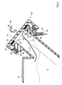
- FIGS 1 to 3 depict a detail of an expansion tank 10 of a radiator of an internal combustion engine of a motor vehicle according to a first embodiment.
- the expansion tank 10 is made of plastic.
- the expansion tank 10 contains coolant 11.
- the expansion tank 10 comprises a filling socket 12 with a filler aperture 14.
- the filling socket 12 is provided with a cupulate cap 16.
- the cap 16 is made of plastic.
- the filling socket 12 and the cap 16 are parts of a closure device 18 for sealing the filler aperture 14.
- the cap 16 is secured to the filling socket 12 by a screw-thread 20, 22.
- the cap 16 has an internal screw-thread 20 which can be engaged with an external screw-thread 22 on the filling socket 12.
- the cap 16 At its bottom the cap 16 is provided with a cylindrical collar 24.
- the collar 24 In the state of closing of the closure device 18, which is shown in figures 1 and 3 , the collar 24 is coaxial to the filling socket 12 and overlaps an end-section 26 of the filling socket 12. The radial inner circumferential of the collar 24 touches the radial outer circumferential of the end-section 26.
- the cap 16 is provided with a sealing ring 28.
- the sealing ring 28 is arranged inside the collar 24 and coaxial to that. It lies flat on the inner surface of the bottom of the cap 16. In the state of closing a bearing face 30 of the sealing ring 28 is pressed in axial direction to the filling socket 12 on an end face 32 of the filling socket 12. The sealing ring 28 so seals the filler aperture 14 in the state of closing.
- An intake section 34 of a drainage channel 36 is integrated in a thickening 38 of the filling socket 12.
- the thickening 38 also is provided with the external screw-thread 22.
- the drainage channel 36 has an intake opening 40 to the end face 32 of the filling socket 12. In the state of closing the intake opening 40 is sealed by the sealing ring 28 too.
- An outlet section 42 of the drainage channel 36 leads out of the thickening 38 and away from the cap 16.
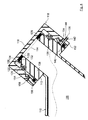
- the drainage channel 36 has a connector 44 for an outlet pipe 46 which is shown in figure 3 .
- the outlet pipe 46 leads to a not shown collecting chamber where escaping coolant can be collected.
- the expansion tank 10, the filling socket 12 and the drainage channel 36 are molded in one piece of plastic.
- the cap 16 For opening the filler aperture 14 the cap 16 is screwed off the filling socket 12.
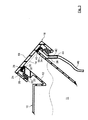
- the sealing ring 28 as a result is moved away from the end face 32 of the filling socket 12 in direction of an arrow 46 as shown in figure 2 .
- a continuously-increasing gap 48 between the sealing ring 28 and the end face 32 then connects the filler aperture 14 with the intake opening 40 of the drainage channel 36.
- the drainage channel 36 for pressure equalization so is connected with the filler aperture 14 when removing the cap 16. Any hot and pressurized coolant and steam in the expansion tank 10 can escape through the gap 48 and the drainage channel 36 as sketched out by a bent arrow 50 and is led away from the cap 16.
- the special closure device 18 prevents that hot and pressurized coolant and steam can escape near the cap 16 when opening the filler aperture 14. So the risk of injury by burning for a person who screws off the cap 16 is reduced.
- Figures 4 and 5 depict a second embodiment of an expansion tank 110. Those parts which are equal to those of the first embodiment according to figures 1 to 3 have the same reference numbers plus 100.
- the closure device 118 of the second embodiment comprises a covering ring 152, which is coaxial to the filling socket 112.
- the covering ring 152 covers an annular opening 154 between the end face of the cap 116 and the outer circumferential side of the filling socket 112.
- the covering ring 152 has in its radial inner circumferential surface a groove with a ring sealing 156.
- the ring sealing 156 presses in radial direction to the filling socket 12 against the radial outer circumferential surface of the thickening 138 of the filling socket 112.
- the intake opening 140 of the intake section 134 of the drainage channel 136 is axially arranged between the end face 132 of the filling socket 112 and the ring sealing 156 of the covering ring 162.
- the intake section 134 extends radial to the filling socket 112.
- the covering ring 152 is attached to the cap 116 by way of a ring-shaped snap joint 158.
- the sealing ring 128 is moved away from the end face 132 of the filling socket 112 in direction of the arrow 146.
- the coolant and steam passes the continuously-increasing gap 148, leaves the cap 116 through a space between the screw-threads 120 and 122 and flows to the intake opening 140 of the drainage channel 136.
- Any hot and pressurized coolant and steam in the expansion tank 110 so can escape through the gap 148, the space between the screw-threads 120 and 122 and the drainage channel 136 as sketched out with a bent arrow 150 and is away from the cap 116.
- the covering ring 152 prevents that coolant and steam can get to surroundings directly through the annular opening 154.
- the invention is not limited to an expansion tank 10; 110 of a radiator of an internal combustion engine of a motor vehicle.
- the invention can also be applied for other kinds of reservoirs especially for fluids which can be hot and/or under high pressure.
- the invention can further be applied to other kinds of internal combustion engines, particularly industrial engines.
- the invention also can be used for fluids different from coolant 11; 111.
- the cap 16; 116 can be secured to the filling socket 12; 112 by interlocking means different from screw-threads 20, 22; 120, 122, preferable by interlocking means, which are interlocked by a rotating and/or plug-in movement of the cap relative to the socket, for example by a plug-in joint or a bayonet joint.
- the cap 16; 116 can be provided with other sealing means, for example a sealing plate, which is suitable for sealing the filler aperture 14; 114 in the state of closing.
- the expansion tank 10; 110 with the filling socket 12; 112 can be made of a material different from plastic.
- the expansion tank 10; 110 can be made of a material different from the material of the filling socket 12; 112.
- the cap 16; 116 can be made of a material different from plastic.
- the drainage channel 36 can also have a number of intake openings to the end face 32 of the filling socket 12.
- the intake opening can also be formed as a slit which expands at least over a part of the circumference of the end face 32.
- the covering ring 152 can be attached to the cap 116 in a different way.
- it can be attached to the cap 116 by means of a plug-in joint, a screw thread or a bayonet joint. It also can be mounted by welding or means of glue.
- the covering ring 152 can also be part of the cap 116.
Landscapes
- Engineering & Computer Science (AREA)
- Chemical & Material Sciences (AREA)
- Combustion & Propulsion (AREA)
- Mechanical Engineering (AREA)
- General Engineering & Computer Science (AREA)
- Cooling, Air Intake And Gas Exhaust, And Fuel Tank Arrangements In Propulsion Units (AREA)
Abstract
Description
- The present invention relates to a closure device for sealing a filler aperture of a reservoir, especially for the use on a radiator of an internal combustion engine in particular of a motor vehicle, comprising a filling socket and a cupulate cap secured to the socket by interlocking means, which are interlocked by a rotating and/or plug-in movement of the cap on the socket, and the cap is provided with sealing means, which seals the filler aperture in the state of closing, and a drainage channel for pressure equalization is connected with the filler aperture when removing the cap.
- The
GB 2 033 351 A - It is an object of the invention to provide a closure device for easy sealing a filler aperture of a reservoir, which can be built easy with a minimum of components and which allows a safe removing of the cap especially if a boiling and pressurised medium is present in the reservoir.
- The object is achieved by that the cap presses in the state of closing the sealing means against the end face of the filling socket for sealing the filler aperture and when removing the cap a gap between the sealing means and the end face connects the filler aperture with the drainage channel.
- Favourably, the filling socket combines both the interlocking function and the sealing function. This reduces the number of components. A separate collar as part of the sealing means is not necessary. When removing the cap any boiling and pressurised medium, in particular coolant and hot steam, can pass to the drainage channel. The medium is drained off with the drainage channel away from the cap. In this way it is prevented that hot medium can hurt a person which removes the cap. Any pressurised hot medium is automatically directed away from the hand of the person when removing the cap. The drainage channel can lead off the reservoir so that no medium escaping from the interior of the reservoir soils the exterior of the reservoir. The drainage channel can lead to a collecting area to prevent that medium can get to surroundings.
- According to a favourable embodiment of the invention, an intake section of the drainage channel can be integrated in a wall of the filling socket and can have an intake opening to the end face, which can be sealed in the state of closing by the sealing means. So the intake section of the drainage channel is space-saving combined with the filling socket. The filling socket and a drainage channel easy can be formed together. In particular the filling socket, the drainage channel and the reservoir can easy be molded in one piece of plastic. The intake opening and the filler aperture can be opened and closed simultaneously with only one sealing means. This reduces the number of components. It also simplifies the manufacturing process.
- According to another favourable embodiment of the invention, a covering ring for an annular opening between the end face of the cap and the outer circumferential side of the filling socket can comprise a ring sealing and an intake section of the drainage channel can be placed in the covering ring and can have an intake opening that is axially arranged between the end face of the socket and the ring sealing of the covering ring. Since the drainage channel is attached to the cap the inventive closure device can be combined easy with a conventional reservoir without modifying an existing filling socket. The covering ring prevents that medium which passes the gap between the cap and the filler socket can escape through the annular opening to surroundings. The medium can be collected in a space which is bounded by the outer circumferential side of the filling socket, the inner circumferential side of the cap and the covering ring. The medium can leave this space through the drainage channel.
- Particularly, the covering ring can be attached to the cap by way of a plug-in joint or a ring-shaped snap joint. In this way the covering ring easy can be fixed to the cap. So an usual cap can be retrofitted with a covering ring. The covering ring also can be attached removable to the cap.
- According to a further favorable embodiment of the invention, an outlet section of the drainage channel can have a connector for an outlet pipe. The outlet pipe can lead far away from the cap for further reducing the risk of injury due to escaping hot medium or steam.
- Advantageously, the sealing means can comprise a sealing ring or a sealing plate. A sealing ring or a sealing plate can be mounted easily in the cap.
- Particularly, the interlocking means can comprise a plug-in joint, a screw-thread or a bayonet joint. The parts of a plug-in joint can easily be combined and separated. A screw-thread has a high stability in axial direction. A bayonet joint can easy be connected and separated and has a high stability in axial direction.
- The present invention together with the above-mentioned and other objects and advantages may best be understood from the following detailed description of the embodiments, but not restricted to the embodiments, wherein is shown schematically
- Figure 1
- a sectional view of an expansion tank of a radiator of an internal combustion engine in the area of closing means for a filling aperture in the state of closing with a drainage channel according to a first embodiment;
- Figure 2
- the expansion tank according to
figure 1 where the closing means is in the state of opening; - Figure 3
- the expansion tank in the area of the closing means according to
figures 1 and2 where an outlet section of the drainage channel is connected to an outlet pipe; - Figure 4
- a sectional view of an expansion tank in the area of closing means according to a second embodiment in the state of closing where a covering ring comprises a drainage channel and is attached to the cap;
- Figure 5
- the expansion tank according to
figure 4 whereby the closing means is in the state of opening. - In the drawings, equal or similar elements are referred to by equal reference numerals. The drawings are merely schematic representations, not intended to portray specific parameters of the invention. Moreover, the drawings are intended to depict only typical embodiments of the invention and therefore should not be considered as limiting the scope of the invention.
-
Figures 1 to 3 depict a detail of anexpansion tank 10 of a radiator of an internal combustion engine of a motor vehicle according to a first embodiment. Theexpansion tank 10 is made of plastic. Theexpansion tank 10 containscoolant 11. - The
expansion tank 10 comprises afilling socket 12 with afiller aperture 14. The fillingsocket 12 is provided with acupulate cap 16. Thecap 16 is made of plastic. The fillingsocket 12 and thecap 16 are parts of aclosure device 18 for sealing thefiller aperture 14. Thecap 16 is secured to the fillingsocket 12 by a screw-thread cap 16 has an internal screw-thread 20 which can be engaged with an external screw-thread 22 on the fillingsocket 12. - At its bottom the
cap 16 is provided with acylindrical collar 24. In the state of closing of theclosure device 18, which is shown infigures 1 and3 , thecollar 24 is coaxial to the fillingsocket 12 and overlaps an end-section 26 of the fillingsocket 12. The radial inner circumferential of thecollar 24 touches the radial outer circumferential of the end-section 26. - The
cap 16 is provided with a sealingring 28. The sealingring 28 is arranged inside thecollar 24 and coaxial to that. It lies flat on the inner surface of the bottom of thecap 16. In the state of closing a bearingface 30 of the sealingring 28 is pressed in axial direction to the fillingsocket 12 on anend face 32 of the fillingsocket 12. The sealingring 28 so seals thefiller aperture 14 in the state of closing. - An
intake section 34 of adrainage channel 36 is integrated in a thickening 38 of the fillingsocket 12. The thickening 38 also is provided with the external screw-thread 22. Thedrainage channel 36 has anintake opening 40 to theend face 32 of the fillingsocket 12. In the state of closing theintake opening 40 is sealed by the sealingring 28 too. - An
outlet section 42 of thedrainage channel 36 leads out of the thickening 38 and away from thecap 16. Thedrainage channel 36 has aconnector 44 for anoutlet pipe 46 which is shown infigure 3 . Theoutlet pipe 46 leads to a not shown collecting chamber where escaping coolant can be collected. - The
expansion tank 10, the fillingsocket 12 and thedrainage channel 36 are molded in one piece of plastic. - For opening the
filler aperture 14 thecap 16 is screwed off the fillingsocket 12. The sealingring 28 as a result is moved away from theend face 32 of the fillingsocket 12 in direction of anarrow 46 as shown infigure 2 . A continuously-increasinggap 48 between the sealingring 28 and theend face 32 then connects thefiller aperture 14 with theintake opening 40 of thedrainage channel 36. Thedrainage channel 36 for pressure equalization so is connected with thefiller aperture 14 when removing thecap 16. Any hot and pressurized coolant and steam in theexpansion tank 10 can escape through thegap 48 and thedrainage channel 36 as sketched out by abent arrow 50 and is led away from thecap 16. - In the starting phase of the removing of the
cap 16 thecollar 24 still overlaps theend section 26 of the fillingsocket 12. So it is prevented that hot and pressurized coolant and steam, which passes thegap 48, can leave thecap 16 through a space between the screw-threads - In total the
special closure device 18 prevents that hot and pressurized coolant and steam can escape near thecap 16 when opening thefiller aperture 14. So the risk of injury by burning for a person who screws off thecap 16 is reduced. -
Figures 4 and5 depict a second embodiment of anexpansion tank 110. Those parts which are equal to those of the first embodiment according tofigures 1 to 3 have the same reference numbers plus 100. Different to the first embodiment, theclosure device 118 of the second embodiment comprises acovering ring 152, which is coaxial to the fillingsocket 112. Thecovering ring 152 covers anannular opening 154 between the end face of thecap 116 and the outer circumferential side of the fillingsocket 112. - The
covering ring 152 has in its radial inner circumferential surface a groove with a ring sealing 156. The ring sealing 156 presses in radial direction to the fillingsocket 12 against the radial outer circumferential surface of the thickening 138 of the fillingsocket 112. - The
intake opening 140 of theintake section 134 of thedrainage channel 136 is axially arranged between theend face 132 of the fillingsocket 112 and the ring sealing 156 of the covering ring 162. Theintake section 134 extends radial to the fillingsocket 112. - The
covering ring 152 is attached to thecap 116 by way of a ring-shaped snap joint 158. - When the
cap 116 is screwed off the fillingsocket 112, as shown infigure 5 , the sealingring 128 is moved away from theend face 132 of the fillingsocket 112 in direction of thearrow 146. The coolant and steam passes the continuously-increasinggap 148, leaves thecap 116 through a space between the screw-threads intake opening 140 of thedrainage channel 136. Any hot and pressurized coolant and steam in theexpansion tank 110 so can escape through thegap 148, the space between the screw-threads drainage channel 136 as sketched out with abent arrow 150 and is away from thecap 116. Thecovering ring 152 prevents that coolant and steam can get to surroundings directly through theannular opening 154. - The invention is not limited to an
expansion tank 10; 110 of a radiator of an internal combustion engine of a motor vehicle. The invention can also be applied for other kinds of reservoirs especially for fluids which can be hot and/or under high pressure. The invention can further be applied to other kinds of internal combustion engines, particularly industrial engines. - The invention also can be used for fluids different from
coolant 11; 111. - The
cap 16; 116 can be secured to the fillingsocket 12; 112 by interlocking means different from screw-threads - Instead with the sealing
ring 28; 128, thecap 16; 116 can be provided with other sealing means, for example a sealing plate, which is suitable for sealing thefiller aperture 14; 114 in the state of closing. - The
expansion tank 10; 110 with the fillingsocket 12; 112 can be made of a material different from plastic. Theexpansion tank 10; 110 can be made of a material different from the material of the fillingsocket 12; 112. Also thecap 16; 116 can be made of a material different from plastic. - With the first embodiment instead of only one
intake opening 40 thedrainage channel 36 can also have a number of intake openings to theend face 32 of the fillingsocket 12. The intake opening can also be formed as a slit which expands at least over a part of the circumference of theend face 32. - Instead of using the ring-shaped snap joint 158. In the second embodiment the
covering ring 152 can be attached to thecap 116 in a different way. For example it can be attached to thecap 116 by means of a plug-in joint, a screw thread or a bayonet joint. It also can be mounted by welding or means of glue. Thecovering ring 152 can also be part of thecap 116.
Claims (7)
- Closure device (18; 118) for sealing a filler aperture (14; 114) of a reservoir (10; 110), especially for the use on a radiator of an internal combustion engine in particular of a motor vehicle, comprising a filling socket (12; 112) and a cupulate cap (16; 116) secured to the socket (12; 112) by interlocking means (20, 22; 120, 122), which are interlocked by a rotating and/or plug-in movement of the cap (16; 116) on the socket (12; 112), and the cap (16; 116) is provided with sealing means (28; 128), which seals the filler aperture (14; 114) in the state of closing, and a drainage channel (36; 136) for pressure equalization is connected with the filler aperture (14; 114) when removing the cap (16; 116), characterized in that the cap (16; 116) presses in the state of closing the sealing means (28; 128) against the end face (32; 132) of the filling socket (12; 112) for sealing the filler aperture (14; 114) and when removing the cap (16; 116) a gap (48; 148) between the sealing means (28; 128) and the end face (32; 132) connects the filler aperture (14; 114) with the drainage channel (36; 136).
- Closure device according to claim 1, characterized in that an intake section (34) of the drainage channel (36) is integrated in a wall (38) of the filling socket (12) and has an intake opening (40) to the end face (32), which is sealed in the state of closing by the sealing means (28).
- Closure device according to claim 1, characterized in that a covering ring (152) for an annular opening (154) between the end face of the cap (116) and the outer circumferential side of the filling socket (112) comprises a ring sealing (156) and an intake section (134) of the drainage channel (136) is placed in the covering ring (152) and has an intake opening (140) that is axially arranged between the end face of the socket (112) and the ring sealing (156) of the covering ring (152).
- Closure device according to claim 3, characterized in that the covering ring (152) is attached to the cap (116) by way of a plug-in joint or a ring-shaped snap joint (158).
- Closure device according to one of the previous claims, characterized in that an outlet section (42; 142) of the drainage channel (36; 136) has a connector (44; 144) for an outlet pipe (46).
- Closure device according to one of the previous claims, characterized in that the sealing means comprises a sealing ring (28; 128) or a sealing plate.
- Closure device according to one of the previous claims, characterized in that the interlocking means comprises a plug-in joint, a screw-thread (20, 22; 120, 122) or a bayonet joint.
Priority Applications (1)
| Application Number | Priority Date | Filing Date | Title |
|---|---|---|---|
| EP20110290359 EP2554817B1 (en) | 2011-08-03 | 2011-08-03 | Closure device for sealing a filler aperture of a reservoir |
Applications Claiming Priority (1)
| Application Number | Priority Date | Filing Date | Title |
|---|---|---|---|
| EP20110290359 EP2554817B1 (en) | 2011-08-03 | 2011-08-03 | Closure device for sealing a filler aperture of a reservoir |
Publications (2)
| Publication Number | Publication Date |
|---|---|
| EP2554817A1 true EP2554817A1 (en) | 2013-02-06 |
| EP2554817B1 EP2554817B1 (en) | 2014-06-25 |
Family
ID=44514583
Family Applications (1)
| Application Number | Title | Priority Date | Filing Date |
|---|---|---|---|
| EP20110290359 Active EP2554817B1 (en) | 2011-08-03 | 2011-08-03 | Closure device for sealing a filler aperture of a reservoir |
Country Status (1)
| Country | Link |
|---|---|
| EP (1) | EP2554817B1 (en) |
Cited By (2)
| Publication number | Priority date | Publication date | Assignee | Title |
|---|---|---|---|---|
| CN105952522A (en) * | 2016-04-30 | 2016-09-21 | 安徽志诚机电零部件有限公司 | Anti-slip filling port of automobile expansion water pot and machining method of anti-slip filling port |
| DE102015208368A1 (en) * | 2015-05-06 | 2016-11-10 | Bayerische Motoren Werke Aktiengesellschaft | cap |
Citations (3)
| Publication number | Priority date | Publication date | Assignee | Title |
|---|---|---|---|---|
| US3077927A (en) * | 1960-05-02 | 1963-02-19 | Ford Motor Co | Cooling system |
| GB2033351A (en) | 1978-10-20 | 1980-05-21 | Bayerische Motoren Werke Ag | Valved closures |
| DE4039993A1 (en) * | 1990-12-14 | 1992-03-26 | Daimler Benz Ag | VENTILATION PIPE IN THE COOLING CIRCUIT OF AN INTERNAL COMBUSTION ENGINE |
-
2011
- 2011-08-03 EP EP20110290359 patent/EP2554817B1/en active Active
Patent Citations (3)
| Publication number | Priority date | Publication date | Assignee | Title |
|---|---|---|---|---|
| US3077927A (en) * | 1960-05-02 | 1963-02-19 | Ford Motor Co | Cooling system |
| GB2033351A (en) | 1978-10-20 | 1980-05-21 | Bayerische Motoren Werke Ag | Valved closures |
| DE4039993A1 (en) * | 1990-12-14 | 1992-03-26 | Daimler Benz Ag | VENTILATION PIPE IN THE COOLING CIRCUIT OF AN INTERNAL COMBUSTION ENGINE |
Cited By (2)
| Publication number | Priority date | Publication date | Assignee | Title |
|---|---|---|---|---|
| DE102015208368A1 (en) * | 2015-05-06 | 2016-11-10 | Bayerische Motoren Werke Aktiengesellschaft | cap |
| CN105952522A (en) * | 2016-04-30 | 2016-09-21 | 安徽志诚机电零部件有限公司 | Anti-slip filling port of automobile expansion water pot and machining method of anti-slip filling port |
Also Published As
| Publication number | Publication date |
|---|---|
| EP2554817B1 (en) | 2014-06-25 |
Similar Documents
| Publication | Publication Date | Title |
|---|---|---|
| JP6058697B2 (en) | Drive device | |
| US10054214B2 (en) | Clippable shutter with a deflector skirt for a steering housing | |
| US10010818B2 (en) | Filter element | |
| US20140116931A1 (en) | Suction-Type oil filter unit for transmissions or internal combustion engines | |
| US9950287B2 (en) | Filter for fluid, filter element of a filter, and filter housing of a filter | |
| US9126129B2 (en) | Filter device and filter element | |
| JP2016531745A (en) | Fluid filter device | |
| EP2554817B1 (en) | Closure device for sealing a filler aperture of a reservoir | |
| US9884274B2 (en) | Filter apparatus | |
| CN104976505B (en) | Gas filling nozzle with safety function | |
| JP6425234B2 (en) | Drainage connector | |
| CN203395314U (en) | Multifunctional universal inflating connector | |
| CN104400393A (en) | Oil seal press-fitting equipment in steering gear shell and press-fitting technology thereof | |
| CN102525260A (en) | Sealing type electric pressure cooker with embedded cooker cover | |
| US10071330B2 (en) | Filter element, in particular for gas filtration | |
| US10478761B2 (en) | Filter device | |
| US20140202947A1 (en) | Liquid Filter | |
| CN107091140A (en) | Vehicle urea filler counter-jetting resistance structure | |
| CN208348076U (en) | The oil device of helical-lobe compressor | |
| WO2014184637A1 (en) | Oil filter construction for internal combustion engines and for machines including oleodynamic circuits | |
| IT201800005168A1 (en) | FITTING ELEMENT AND CONNECTION KIT | |
| CN103318827B (en) | A kind of portable heating oil nozzle for oil bottle | |
| CN118323457B (en) | Precipitation structure is put to inside oil tank of aircraft organism | |
| SE1550703A1 (en) | Oil filter arrangement | |
| CN201615109U (en) | Rotary power device |
Legal Events
| Date | Code | Title | Description |
|---|---|---|---|
| PUAI | Public reference made under article 153(3) epc to a published international application that has entered the european phase |
Free format text: ORIGINAL CODE: 0009012 |
|
| AK | Designated contracting states |
Kind code of ref document: A1 Designated state(s): AL AT BE BG CH CY CZ DE DK EE ES FI FR GB GR HR HU IE IS IT LI LT LU LV MC MK MT NL NO PL PT RO RS SE SI SK SM TR |
|
| AX | Request for extension of the european patent |
Extension state: BA ME |
|
| 17P | Request for examination filed |
Effective date: 20130730 |
|
| RBV | Designated contracting states (corrected) |
Designated state(s): AL AT BE BG CH CY CZ DE DK EE ES FI FR GB GR HR HU IE IS IT LI LT LU LV MC MK MT NL NO PL PT RO RS SE SI SK SM TR |
|
| GRAP | Despatch of communication of intention to grant a patent |
Free format text: ORIGINAL CODE: EPIDOSNIGR1 |
|
| RIN1 | Information on inventor provided before grant (corrected) |
Inventor name: GIRARD, DOMINIQUE Inventor name: TROTIN, PHILIPPE Inventor name: BLANC-BRUDE, GUILLAUME |
|
| INTG | Intention to grant announced |
Effective date: 20140131 |
|
| GRAS | Grant fee paid |
Free format text: ORIGINAL CODE: EPIDOSNIGR3 |
|
| GRAA | (expected) grant |
Free format text: ORIGINAL CODE: 0009210 |
|
| AK | Designated contracting states |
Kind code of ref document: B1 Designated state(s): AL AT BE BG CH CY CZ DE DK EE ES FI FR GB GR HR HU IE IS IT LI LT LU LV MC MK MT NL NO PL PT RO RS SE SI SK SM TR |
|
| REG | Reference to a national code |
Ref country code: GB Ref legal event code: FG4D |
|
| REG | Reference to a national code |
Ref country code: CH Ref legal event code: EP |
|
| REG | Reference to a national code |
Ref country code: AT Ref legal event code: REF Ref document number: 674864 Country of ref document: AT Kind code of ref document: T Effective date: 20140715 |
|
| REG | Reference to a national code |
Ref country code: IE Ref legal event code: FG4D |
|
| REG | Reference to a national code |
Ref country code: DE Ref legal event code: R096 Ref document number: 602011007919 Country of ref document: DE Effective date: 20140807 |
|
| PG25 | Lapsed in a contracting state [announced via postgrant information from national office to epo] |
Ref country code: GR Free format text: LAPSE BECAUSE OF FAILURE TO SUBMIT A TRANSLATION OF THE DESCRIPTION OR TO PAY THE FEE WITHIN THE PRESCRIBED TIME-LIMIT Effective date: 20140926 Ref country code: LT Free format text: LAPSE BECAUSE OF FAILURE TO SUBMIT A TRANSLATION OF THE DESCRIPTION OR TO PAY THE FEE WITHIN THE PRESCRIBED TIME-LIMIT Effective date: 20140625 Ref country code: CY Free format text: LAPSE BECAUSE OF FAILURE TO SUBMIT A TRANSLATION OF THE DESCRIPTION OR TO PAY THE FEE WITHIN THE PRESCRIBED TIME-LIMIT Effective date: 20140625 Ref country code: NO Free format text: LAPSE BECAUSE OF FAILURE TO SUBMIT A TRANSLATION OF THE DESCRIPTION OR TO PAY THE FEE WITHIN THE PRESCRIBED TIME-LIMIT Effective date: 20140925 Ref country code: FI Free format text: LAPSE BECAUSE OF FAILURE TO SUBMIT A TRANSLATION OF THE DESCRIPTION OR TO PAY THE FEE WITHIN THE PRESCRIBED TIME-LIMIT Effective date: 20140625 |
|
| REG | Reference to a national code |
Ref country code: AT Ref legal event code: MK05 Ref document number: 674864 Country of ref document: AT Kind code of ref document: T Effective date: 20140625 |
|
| REG | Reference to a national code |
Ref country code: NL Ref legal event code: VDEP Effective date: 20140625 |
|
| REG | Reference to a national code |
Ref country code: LT Ref legal event code: MG4D |
|
| PG25 | Lapsed in a contracting state [announced via postgrant information from national office to epo] |
Ref country code: SE Free format text: LAPSE BECAUSE OF FAILURE TO SUBMIT A TRANSLATION OF THE DESCRIPTION OR TO PAY THE FEE WITHIN THE PRESCRIBED TIME-LIMIT Effective date: 20140625 Ref country code: LV Free format text: LAPSE BECAUSE OF FAILURE TO SUBMIT A TRANSLATION OF THE DESCRIPTION OR TO PAY THE FEE WITHIN THE PRESCRIBED TIME-LIMIT Effective date: 20140625 Ref country code: RS Free format text: LAPSE BECAUSE OF FAILURE TO SUBMIT A TRANSLATION OF THE DESCRIPTION OR TO PAY THE FEE WITHIN THE PRESCRIBED TIME-LIMIT Effective date: 20140625 Ref country code: HR Free format text: LAPSE BECAUSE OF FAILURE TO SUBMIT A TRANSLATION OF THE DESCRIPTION OR TO PAY THE FEE WITHIN THE PRESCRIBED TIME-LIMIT Effective date: 20140625 |
|
| PG25 | Lapsed in a contracting state [announced via postgrant information from national office to epo] |
Ref country code: ES Free format text: LAPSE BECAUSE OF FAILURE TO SUBMIT A TRANSLATION OF THE DESCRIPTION OR TO PAY THE FEE WITHIN THE PRESCRIBED TIME-LIMIT Effective date: 20140625 Ref country code: CZ Free format text: LAPSE BECAUSE OF FAILURE TO SUBMIT A TRANSLATION OF THE DESCRIPTION OR TO PAY THE FEE WITHIN THE PRESCRIBED TIME-LIMIT Effective date: 20140625 Ref country code: RO Free format text: LAPSE BECAUSE OF FAILURE TO SUBMIT A TRANSLATION OF THE DESCRIPTION OR TO PAY THE FEE WITHIN THE PRESCRIBED TIME-LIMIT Effective date: 20140625 Ref country code: SK Free format text: LAPSE BECAUSE OF FAILURE TO SUBMIT A TRANSLATION OF THE DESCRIPTION OR TO PAY THE FEE WITHIN THE PRESCRIBED TIME-LIMIT Effective date: 20140625 Ref country code: PT Free format text: LAPSE BECAUSE OF FAILURE TO SUBMIT A TRANSLATION OF THE DESCRIPTION OR TO PAY THE FEE WITHIN THE PRESCRIBED TIME-LIMIT Effective date: 20141027 Ref country code: EE Free format text: LAPSE BECAUSE OF FAILURE TO SUBMIT A TRANSLATION OF THE DESCRIPTION OR TO PAY THE FEE WITHIN THE PRESCRIBED TIME-LIMIT Effective date: 20140625 |
|
| PG25 | Lapsed in a contracting state [announced via postgrant information from national office to epo] |
Ref country code: IS Free format text: LAPSE BECAUSE OF FAILURE TO SUBMIT A TRANSLATION OF THE DESCRIPTION OR TO PAY THE FEE WITHIN THE PRESCRIBED TIME-LIMIT Effective date: 20141025 Ref country code: NL Free format text: LAPSE BECAUSE OF FAILURE TO SUBMIT A TRANSLATION OF THE DESCRIPTION OR TO PAY THE FEE WITHIN THE PRESCRIBED TIME-LIMIT Effective date: 20140625 Ref country code: AT Free format text: LAPSE BECAUSE OF FAILURE TO SUBMIT A TRANSLATION OF THE DESCRIPTION OR TO PAY THE FEE WITHIN THE PRESCRIBED TIME-LIMIT Effective date: 20140625 Ref country code: PL Free format text: LAPSE BECAUSE OF FAILURE TO SUBMIT A TRANSLATION OF THE DESCRIPTION OR TO PAY THE FEE WITHIN THE PRESCRIBED TIME-LIMIT Effective date: 20140625 |
|
| REG | Reference to a national code |
Ref country code: DE Ref legal event code: R119 Ref document number: 602011007919 Country of ref document: DE |
|
| PG25 | Lapsed in a contracting state [announced via postgrant information from national office to epo] |
Ref country code: MC Free format text: LAPSE BECAUSE OF FAILURE TO SUBMIT A TRANSLATION OF THE DESCRIPTION OR TO PAY THE FEE WITHIN THE PRESCRIBED TIME-LIMIT Effective date: 20140625 Ref country code: LU Free format text: LAPSE BECAUSE OF FAILURE TO SUBMIT A TRANSLATION OF THE DESCRIPTION OR TO PAY THE FEE WITHIN THE PRESCRIBED TIME-LIMIT Effective date: 20140803 |
|
| REG | Reference to a national code |
Ref country code: CH Ref legal event code: PL |
|
| PLBI | Opposition filed |
Free format text: ORIGINAL CODE: 0009260 |
|
| PG25 | Lapsed in a contracting state [announced via postgrant information from national office to epo] |
Ref country code: LI Free format text: LAPSE BECAUSE OF NON-PAYMENT OF DUE FEES Effective date: 20140831 Ref country code: DK Free format text: LAPSE BECAUSE OF FAILURE TO SUBMIT A TRANSLATION OF THE DESCRIPTION OR TO PAY THE FEE WITHIN THE PRESCRIBED TIME-LIMIT Effective date: 20140625 Ref country code: BE Free format text: LAPSE BECAUSE OF NON-PAYMENT OF DUE FEES Effective date: 20140831 Ref country code: IT Free format text: LAPSE BECAUSE OF FAILURE TO SUBMIT A TRANSLATION OF THE DESCRIPTION OR TO PAY THE FEE WITHIN THE PRESCRIBED TIME-LIMIT Effective date: 20140625 Ref country code: CH Free format text: LAPSE BECAUSE OF NON-PAYMENT OF DUE FEES Effective date: 20140831 |
|
| 26 | Opposition filed |
Opponent name: MAHLE INTERNATIONAL GMBH Effective date: 20150325 |
|
| PLAX | Notice of opposition and request to file observation + time limit sent |
Free format text: ORIGINAL CODE: EPIDOSNOBS2 |
|
| REG | Reference to a national code |
Ref country code: IE Ref legal event code: MM4A |
|
| REG | Reference to a national code |
Ref country code: DE Ref legal event code: R119 Ref document number: 602011007919 Country of ref document: DE Effective date: 20150303 |
|
| PG25 | Lapsed in a contracting state [announced via postgrant information from national office to epo] |
Ref country code: BE Free format text: LAPSE BECAUSE OF FAILURE TO SUBMIT A TRANSLATION OF THE DESCRIPTION OR TO PAY THE FEE WITHIN THE PRESCRIBED TIME-LIMIT Effective date: 20140625 |
|
| PG25 | Lapsed in a contracting state [announced via postgrant information from national office to epo] |
Ref country code: DE Free format text: LAPSE BECAUSE OF NON-PAYMENT OF DUE FEES Effective date: 20150303 |
|
| PG25 | Lapsed in a contracting state [announced via postgrant information from national office to epo] |
Ref country code: IE Free format text: LAPSE BECAUSE OF NON-PAYMENT OF DUE FEES Effective date: 20140803 |
|
| PLAF | Information modified related to communication of a notice of opposition and request to file observations + time limit |
Free format text: ORIGINAL CODE: EPIDOSCOBS2 |
|
| PG25 | Lapsed in a contracting state [announced via postgrant information from national office to epo] |
Ref country code: SI Free format text: LAPSE BECAUSE OF FAILURE TO SUBMIT A TRANSLATION OF THE DESCRIPTION OR TO PAY THE FEE WITHIN THE PRESCRIBED TIME-LIMIT Effective date: 20140625 |
|
| GBPC | Gb: european patent ceased through non-payment of renewal fee |
Effective date: 20150803 |
|
| PG25 | Lapsed in a contracting state [announced via postgrant information from national office to epo] |
Ref country code: SM Free format text: LAPSE BECAUSE OF FAILURE TO SUBMIT A TRANSLATION OF THE DESCRIPTION OR TO PAY THE FEE WITHIN THE PRESCRIBED TIME-LIMIT Effective date: 20140625 |
|
| PG25 | Lapsed in a contracting state [announced via postgrant information from national office to epo] |
Ref country code: BG Free format text: LAPSE BECAUSE OF FAILURE TO SUBMIT A TRANSLATION OF THE DESCRIPTION OR TO PAY THE FEE WITHIN THE PRESCRIBED TIME-LIMIT Effective date: 20140625 Ref country code: MT Free format text: LAPSE BECAUSE OF FAILURE TO SUBMIT A TRANSLATION OF THE DESCRIPTION OR TO PAY THE FEE WITHIN THE PRESCRIBED TIME-LIMIT Effective date: 20140625 |
|
| PG25 | Lapsed in a contracting state [announced via postgrant information from national office to epo] |
Ref country code: GB Free format text: LAPSE BECAUSE OF NON-PAYMENT OF DUE FEES Effective date: 20150803 Ref country code: TR Free format text: LAPSE BECAUSE OF FAILURE TO SUBMIT A TRANSLATION OF THE DESCRIPTION OR TO PAY THE FEE WITHIN THE PRESCRIBED TIME-LIMIT Effective date: 20140625 Ref country code: HU Free format text: LAPSE BECAUSE OF FAILURE TO SUBMIT A TRANSLATION OF THE DESCRIPTION OR TO PAY THE FEE WITHIN THE PRESCRIBED TIME-LIMIT; INVALID AB INITIO Effective date: 20110803 |
|
| REG | Reference to a national code |
Ref country code: FR Ref legal event code: PLFP Year of fee payment: 6 |
|
| REG | Reference to a national code |
Ref country code: FR Ref legal event code: PLFP Year of fee payment: 7 |
|
| PG25 | Lapsed in a contracting state [announced via postgrant information from national office to epo] |
Ref country code: MK Free format text: LAPSE BECAUSE OF FAILURE TO SUBMIT A TRANSLATION OF THE DESCRIPTION OR TO PAY THE FEE WITHIN THE PRESCRIBED TIME-LIMIT Effective date: 20140625 |
|
| REG | Reference to a national code |
Ref country code: FR Ref legal event code: PLFP Year of fee payment: 8 |
|
| PG25 | Lapsed in a contracting state [announced via postgrant information from national office to epo] |
Ref country code: AL Free format text: LAPSE BECAUSE OF FAILURE TO SUBMIT A TRANSLATION OF THE DESCRIPTION OR TO PAY THE FEE WITHIN THE PRESCRIBED TIME-LIMIT Effective date: 20140625 |
|
| PLBP | Opposition withdrawn |
Free format text: ORIGINAL CODE: 0009264 |
|
| PLBD | Termination of opposition procedure: decision despatched |
Free format text: ORIGINAL CODE: EPIDOSNOPC1 |
|
| PLBM | Termination of opposition procedure: date of legal effect published |
Free format text: ORIGINAL CODE: 0009276 |
|
| STAA | Information on the status of an ep patent application or granted ep patent |
Free format text: STATUS: OPPOSITION PROCEDURE CLOSED |
|
| 27C | Opposition proceedings terminated |
Effective date: 20190130 |
|
| PGFP | Annual fee paid to national office [announced via postgrant information from national office to epo] |
Ref country code: FR Payment date: 20250829 Year of fee payment: 15 |