EP2554800A2 - Methods and apparatus for modifying a turbine casing - Google Patents
Methods and apparatus for modifying a turbine casing Download PDFInfo
- Publication number
- EP2554800A2 EP2554800A2 EP12177919A EP12177919A EP2554800A2 EP 2554800 A2 EP2554800 A2 EP 2554800A2 EP 12177919 A EP12177919 A EP 12177919A EP 12177919 A EP12177919 A EP 12177919A EP 2554800 A2 EP2554800 A2 EP 2554800A2
- Authority
- EP
- European Patent Office
- Prior art keywords
- retention pin
- casing
- ring segments
- patch ring
- bores
- Prior art date
- Legal status (The legal status is an assumption and is not a legal conclusion. Google has not performed a legal analysis and makes no representation as to the accuracy of the status listed.)
- Withdrawn
Links
- 238000000034 method Methods 0.000 title claims abstract description 25
- 230000014759 maintenance of location Effects 0.000 claims abstract description 138
- 238000010586 diagram Methods 0.000 description 7
- 230000008439 repair process Effects 0.000 description 3
- 239000000523 sample Substances 0.000 description 2
- 230000000712 assembly Effects 0.000 description 1
- 238000000429 assembly Methods 0.000 description 1
- 238000006243 chemical reaction Methods 0.000 description 1
- 230000006835 compression Effects 0.000 description 1
- 238000007906 compression Methods 0.000 description 1
- 230000000694 effects Effects 0.000 description 1
- 239000000463 material Substances 0.000 description 1
- 238000012986 modification Methods 0.000 description 1
- 230000004048 modification Effects 0.000 description 1
Images


Classifications
-
- F—MECHANICAL ENGINEERING; LIGHTING; HEATING; WEAPONS; BLASTING
- F01—MACHINES OR ENGINES IN GENERAL; ENGINE PLANTS IN GENERAL; STEAM ENGINES
- F01D—NON-POSITIVE DISPLACEMENT MACHINES OR ENGINES, e.g. STEAM TURBINES
- F01D25/00—Component parts, details, or accessories, not provided for in, or of interest apart from, other groups
- F01D25/24—Casings; Casing parts, e.g. diaphragms, casing fastenings
- F01D25/246—Fastening of diaphragms or stator-rings
-
- F—MECHANICAL ENGINEERING; LIGHTING; HEATING; WEAPONS; BLASTING
- F05—INDEXING SCHEMES RELATING TO ENGINES OR PUMPS IN VARIOUS SUBCLASSES OF CLASSES F01-F04
- F05D—INDEXING SCHEME FOR ASPECTS RELATING TO NON-POSITIVE-DISPLACEMENT MACHINES OR ENGINES, GAS-TURBINES OR JET-PROPULSION PLANTS
- F05D2230/00—Manufacture
- F05D2230/80—Repairing, retrofitting or upgrading methods
-
- F—MECHANICAL ENGINEERING; LIGHTING; HEATING; WEAPONS; BLASTING
- F05—INDEXING SCHEMES RELATING TO ENGINES OR PUMPS IN VARIOUS SUBCLASSES OF CLASSES F01-F04
- F05D—INDEXING SCHEME FOR ASPECTS RELATING TO NON-POSITIVE-DISPLACEMENT MACHINES OR ENGINES, GAS-TURBINES OR JET-PROPULSION PLANTS
- F05D2240/00—Components
- F05D2240/10—Stators
- F05D2240/11—Shroud seal segments
-
- Y—GENERAL TAGGING OF NEW TECHNOLOGICAL DEVELOPMENTS; GENERAL TAGGING OF CROSS-SECTIONAL TECHNOLOGIES SPANNING OVER SEVERAL SECTIONS OF THE IPC; TECHNICAL SUBJECTS COVERED BY FORMER USPC CROSS-REFERENCE ART COLLECTIONS [XRACs] AND DIGESTS
- Y10—TECHNICAL SUBJECTS COVERED BY FORMER USPC
- Y10T—TECHNICAL SUBJECTS COVERED BY FORMER US CLASSIFICATION
- Y10T29/00—Metal working
- Y10T29/49—Method of mechanical manufacture
- Y10T29/49229—Prime mover or fluid pump making
- Y10T29/49236—Fluid pump or compressor making
- Y10T29/49238—Repairing, converting, servicing or salvaging
Definitions
- This invention generally relates to turbines and in particular to modifying a turbine casing.
- Blades or "buckets” are utilized in turbines for conversion of energy.
- the buckets are typically attached by one end to a rotor, while the opposite ends extend nearly to a circumferential casing associated with the turbine.
- a gap between the bucket ends and the casing is usually made as small as possible to minimize flow around the blade ends.
- certain conditions can arise that may cause the blade ends to scrape against the casing and damage the casing surface, and as a result, repairs are sometimes required.
- patch ring segments or shims Such materials can be attached to the inner diameter of the casing to repair the damaged casing surface.
- the patch ring segments can be secured with screws, but there is always a risk that a displaced screw may fall into the flow path and damage other components.
- Certain embodiments of the invention may include systems, methods, and apparatus for modifying a turbine casing
- a method for modifying a turbine casing can include providing one or more casing retention pin bores in the turbine casing; inserting a retention pin in the one or more casing retention pin bores; providing one or more patch ring segments configured to be radially constrained by at least a portion of the turbine casing and further configured to slide circumferentially in cooperation with at least a portion of the turbine casing, wherein the one or more patch ring segments comprise at least one retention pin locking bore; installing the one or more patch ring segments in the turbine casing to radially constrain the one or more patch ring segments; and engaging the retention pin in the at least one retention pin locking bore to circumferentially constrain the one or more patch ring segments to the turbine casing.
- an assembly for repairing a casing associated with a gas turbine flow path stage can include one or more casing retention pin bores in the casing; a retention pin in the one or more casing retention pin bores; and one or more patch ring segments configured to be radially constrained by at least a portion of the casing and further configured to slide circumferentially during assembly or disassembly in cooperation with at least a portion of the turbine casing, wherein the one or more patch ring segments comprise at least one retention pin locking bore, and wherein the retention pin engages with the at least one retention pin locking bore to circumferentially constrain the one or more patch ring segments to the casing.
- a system can include a gas turbine, which may include a flow path stage casing.
- the system includes the assembly for repairing the casing as described above
- Certain example embodiments of the invention may enable attaching and securing the patch ring segments to the turbine casing.
- gas turbines casings may be repaired with patch rings when the flow path on the casing is damaged due to rubs or failure of rotor blades.
- grooves or slots may be made on the damaged flow path, and patch rings may slide into the grooves or slots to build the casing back to the desired casing dimension.
- the patch rings can be made in 6-12 segments for ease of assembly.
- the patch ring segments may not necessarily be an integral part of the casing, and gaps between each patch ring segment may be designed to account for the thermal growth during the gas turbine operation and/or to minimize stresses developed due to the thermal growth in each segment.
- the patch ring segments may be individually secured to the casing by embodiments of the invention.
- segment gaps may accumulate to create creating a larger gap, and may create an aerodynamic concern
- instrumentation wires or probes pass through the patch ring, and if the patch ring moves, then the probes may bend or may shear due to the relative movement of patch ring with the casing.
- spring-loaded pins may reside in bore holes in the casing, and may engage in locking bores in the patch ring sections to constrain the patch rings while averting the risk of falling into the flow path.
- the turbine casing may be modified to accept sections of a patch ring 302.
- a "T" shaped channel may be machined circumferentially into the turbine casing.
- a corresponding "T" shaped machined or attached protrusion on the patch ring section may slide into the casing channel to provide radial constraint of the patch ring sections against the casing, while allowing the patch ring sections to slide into place.
- the patch ring sections may be constrained in the circumferential or axial direction with the retention pin 304.
- the retention pin 304 may have a chamfer and the patch ring 302 may have a guide slot 308 or groove on top of it so that the pin 304 may be guided into the retention pin locking bore 306.
- the method 700 starts in block 702 and includes providing one or more casing retention pin bores in the turbine casing.
- method 700 includes inserting a retention pin in the one or more casing retention pin bores.
- method 700 includes providing one or more patch ring segments configured to be radially constrained by at least a portion of the turbine casing and further configured to slide circumferentially in cooperation with at least a portion of the turbine casing, wherein the one or more patch ring segments comprise at least one retention pin locking bore.
- method 700 includes installing the one or more patch ring segments in the turbine casing to radially constrain the one or more patch ring segments..
- method 700 includes engaging the retention pin in the at least one retention pin locking bore to circumferentially constrain the one or more patch ring segments to the turbine casing. Method 700 ends after block 710.
- engaging the retention pin (304) in the at least one retention pin locking bore (510) includes engaging at least a portion of the retention pin (304) in at least one of the one or more casing retention pin bores (414), and further engaging at least a portion of the retention pin (304) in the at least one retention pin locking bore (510) when the one or more casing retention pin bores (414) are circumferentially aligned with the at least one retention pin locking bore (510).
- Example embodiments include inserting a spring (408) in the one or more casing retention pin bores (414), wherein the spring (408) provides force for engaging the retention pin (304) in the at least one retention pin locking bore (410).
- providing one or more casing retention pin bores (414) in the turbine casing (404) includes providing one or more radial bores in the turbine casing (404).
- installing the one or more patch ring segments (402) in the turbine casing (404) includes installing the one or more patch ring segments (402) in a flow path stage (204) associated with the turbine.
- providing one or more patch ring segments (402) further includes providing a guide slot (308) in the one or more patch ring segments (402) for guiding the retention pin (304) into the at least one retention pin locking bore (410).
- providing one or more patch ring segments (402) further includes providing a retention pin retraction bore (512) for disengaging the retention pin (304) from the least one retention pin locking bore (410), wherein the retention pin retraction bore (512) includes a diameter smaller than the diameter of the retention pin (304).
- Example embodiments of the invention include system and an apparatus.
- the system can include a gas turbine (100) that includes a flow path stage casing (404).
- the system and the apparatus can include an assembly for repairing the casing (404).
- the assembly can include one or more casing retention pin bores (414) in the casing (404); a retention pin (304) in the one or more casing retention pin bores (414); one or more patch ring segments (402) configured to be radially constrained by at least a portion of the casing (404) and further configured to slide circumferentially during assembly or disassembly in cooperation with at least a portion of the turbine casing (404), wherein the one or more patch ring segments include at least one retention pin locking bore (510), and wherein the retention pin (304) engages with the at least one retention pin locking bore (510) to circumferentially constrain the one or more patch ring segments (402) to the casing (404).
- the retention pin is operable to engage with at least a portion of one of the one or more casing retention pin bores (414), and wherein the retention pin is further operable to engage with at least a portion of the at least one retention pin locking bore (510) when the one or more casing retention pin bores (414) are circumferentially aligned with the at least one retention pin locking bore (510).
- the system and/or the apparatus can include a spring (408) positioned in the one or more casing retention pin bores (414), wherein the spring (408) provides force for engaging the retention pin (304) in the at least one retention pin locking bore (410).
- the one or more casing retention pin bores (414) include radial bores in the casing (404).
- the one or more patch ring segments (402) further include a guide slot (308) for guiding the retention pin (304) into the at least one retention pin locking bore (410).
- the one or more patch ring segments (402) further include a retention pin retraction bore (512) for disengaging the retention pin (304) from the least one retention pin locking bore (410), wherein the retention pin retraction bore (512) includes a diameter smaller than the diameter of the retention pin (304).
- certain technical effects can be provided, such as creating certain systems, methods, and apparatus that provide securing patch ring segments to a turbine casing while avoiding the use of screws or other fastening devices that could fall in the flow path.
- the assembly 300, 400, 500, and 600 may include any number of hardware components to facilitate any of the operations described by the methods described herein, such as 700 in FIG. 7 .
Landscapes
- Engineering & Computer Science (AREA)
- Mechanical Engineering (AREA)
- General Engineering & Computer Science (AREA)
- Turbine Rotor Nozzle Sealing (AREA)
Abstract
A method is provided for modifying a turbine casing (404). The method includes providing one or more casing retention pin bores (414) in the turbine casing (404); inserting a retention pin in the one or more casing retention pin bores (414); providing one or more patch ring segments (402) configured to be radially constrained by at least a portion of the turbine casing (404) and further configured to slide circumferentially in cooperation with at least a portion of the turbine casing (404), wherein the one or more patch ring segments (402) comprise at least one retention pin locking bore (510); installing the one or more patch ring segments (402) in the turbine casing (404) to radially constrain the one or more patch ring segments (402); and engaging the retention pin in the at least one retention pin locking bore (410) to circumferentially constrain the one or more patch ring segments (402) to the turbine casing (404).
Description
- This invention generally relates to turbines and in particular to modifying a turbine casing.
- Blades or "buckets" are utilized in turbines for conversion of energy. The buckets are typically attached by one end to a rotor, while the opposite ends extend nearly to a circumferential casing associated with the turbine. A gap between the bucket ends and the casing is usually made as small as possible to minimize flow around the blade ends. During the operation of the turbine, certain conditions can arise that may cause the blade ends to scrape against the casing and damage the casing surface, and as a result, repairs are sometimes required. It is a common practice to repair a damaged turbine casing using patch ring segments or shims. Such materials can be attached to the inner diameter of the casing to repair the damaged casing surface. The patch ring segments can be secured with screws, but there is always a risk that a displaced screw may fall into the flow path and damage other components.
- Some or all of the above needs may be addressed by certain embodiments of the invention. Certain embodiments of the invention may include systems, methods, and apparatus for modifying a turbine casing
- According to a first aspect of the invention, a method is provided for modifying a turbine casing. The method can include providing one or more casing retention pin bores in the turbine casing; inserting a retention pin in the one or more casing retention pin bores; providing one or more patch ring segments configured to be radially constrained by at least a portion of the turbine casing and further configured to slide circumferentially in cooperation with at least a portion of the turbine casing, wherein the one or more patch ring segments comprise at least one retention pin locking bore; installing the one or more patch ring segments in the turbine casing to radially constrain the one or more patch ring segments; and engaging the retention pin in the at least one retention pin locking bore to circumferentially constrain the one or more patch ring segments to the turbine casing.
- According to another aspect of the invention, an assembly for repairing a casing associated with a gas turbine flow path stage is provided. The assembly can include one or more casing retention pin bores in the casing; a retention pin in the one or more casing retention pin bores; and one or more patch ring segments configured to be radially constrained by at least a portion of the casing and further configured to slide circumferentially during assembly or disassembly in cooperation with at least a portion of the turbine casing, wherein the one or more patch ring segments comprise at least one retention pin locking bore, and wherein the retention pin engages with the at least one retention pin locking bore to circumferentially constrain the one or more patch ring segments to the casing.
- According to yet another aspect of the invention, a system is provided. The system can include a gas turbine, which may include a flow path stage casing. The system includes the assembly for repairing the casing as described above
- Other embodiments, features, and aspects of the invention are described in detail herein and are considered a part of the claimed inventions. Other embodiments, features, and aspects can be understood with reference to the following detailed description, accompanying drawings, and claims.
- Embodiments of the present invention will now be described, by way of example only, with reference to the accompanying drawings in which:
-
FIG. 1 is a diagram of an illustrative turbine according to an example embodiment of the invention. -
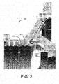
FIG. 2 is a diagram of a illustrative flow path stages of a turbine according to an example embodiment of the invention. -
FIG. 3 is a perspective view diagram of an illustrative patch ring according to an example embodiment of the invention. -
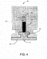
FIG. 4 is a diagram of an illustrative patch ring assembly according to an example embodiment of the invention. -
FIG. 5 is a diagram of an illustrative patch ring assembly with an engaged retention pin according to an example embodiment of the invention. -
FIG. 6 is a diagram of an illustrative patch ring assembly with pin retraction tool according to an example embodiment of the invention. -
FIG. 7 is a flow diagram of an example method according to an example embodiment of the invention. - Embodiments of the invention will be described more fully hereinafter with reference to the accompanying drawings, in which embodiments of the invention are shown. This invention may, however, be embodied in many different forms and should not be construed as limited to the embodiments set forth herein; rather, these embodiments are provided so that this disclosure will be thorough and complete, and will fully convey the scope of the invention to those skilled in the art. Like numbers refer to like elements throughout.
- Certain example embodiments of the invention may enable attaching and securing the patch ring segments to the turbine casing. According to certain example embodiments, gas turbines casings may be repaired with patch rings when the flow path on the casing is damaged due to rubs or failure of rotor blades. According to example embodiments, grooves or slots may be made on the damaged flow path, and patch rings may slide into the grooves or slots to build the casing back to the desired casing dimension.
- From a practical standpoint, it can be very difficult to slide a patch ring into casing grooves or slots when the patch ring is comprised of only a few segments. Therefore, according to an example embodiment of the invention, the patch rings can be made in 6-12 segments for ease of assembly. After assembly, the patch ring segments may not necessarily be an integral part of the casing, and gaps between each patch ring segment may be designed to account for the thermal growth during the gas turbine operation and/or to minimize stresses developed due to the thermal growth in each segment. According to an example embodiment, the patch ring segments may be individually secured to the casing by embodiments of the invention. This may be important for at least two reasons: (1) without securing the patch ring segments to avoid circumferential movement, segment gaps may accumulate to create creating a larger gap, and may create an aerodynamic concern, and (2) if instrumentation wires or probes pass through the patch ring, and if the patch ring moves, then the probes may bend or may shear due to the relative movement of patch ring with the casing.
- Various assemblies and parts for attaching and securing the patch ring segments to the turbine casing will now be described with reference to the accompanying figures according to example embodiments of the invention. According to an example embodiment, spring-loaded pins may reside in bore holes in the casing, and may engage in locking bores in the patch ring sections to constrain the patch rings while averting the risk of falling into the flow path.
-
FIG. 1 depicts aturbine 100 with aflow path 102. The flow path may include buckets or blades that are attached to a rotor. Theflow path 102 may be surrounded by a casing. Theflow path 102 may include one ormore stages 104 for which embodiments of the invention may be applied. -
FIG. 2 depicts a close-up view of theturbine casing 200 showing flow path stages. The turbine casing may include multiple flow path stage interfaces. For example, stage nflow path interface 204 and/or a stage n+1flow path interface 202 may be damaged and may need to be repaired. -
FIG. 3 depicts a perspective view of an illustrativepatch ring assembly 300 according to an example embodiment of the invention. In an example embodiment, thepatch ring assembly 300 may include apatch ring section 302, aretention pin 304, a retentionpin locking bore 306, and anoptional guide slot 308. - According to an example embodiment, the turbine casing may be modified to accept sections of a
patch ring 302. In an example embodiment, a "T" shaped channel may be machined circumferentially into the turbine casing. A corresponding "T" shaped machined or attached protrusion on the patch ring section may slide into the casing channel to provide radial constraint of the patch ring sections against the casing, while allowing the patch ring sections to slide into place. According to an example embodiment, the patch ring sections may be constrained in the circumferential or axial direction with theretention pin 304. According to an example embodiment, theretention pin 304 may have a chamfer and thepatch ring 302 may have aguide slot 308 or groove on top of it so that thepin 304 may be guided into the retentionpin locking bore 306. -
FIG. 4 depicts another view of theassembly 400 in an unlocked position, according to an example embodiment of the invention. Theassembly 400 can include apatch ring segment 402, a portion of theturbine casing 404, a retention pin 406 (shown retracted into the casing retention pin bore 414), acompression spring 408, and a retentionpin locking bore 410. In an example embodiment, theretention pin 406 may reside in thebore 414 within thecasing 404, and may be loaded with thespring 408 so that theretention pin 406 can engage in the retentionpin locking bore 410 within thepatch ring segment 402 when the casingretention pin bore 414 aligns with the retentionpin locking bore 410. -
FIG. 5 depicts another view of theassembly 500 in a locked position. In accordance with an example embodiment of the invention, the patch ring segment (as in 402 of -
FIG. 4 ) may be positioned so that theretention pin 506 can engage with the retentionpin locking bore 510. According to an example embodiment, thespring 508 may provide pressure to hold theretention pin 506 into the locking bore 510. In an example embodiment, when theretention pin 506 is engaged in the locking bore 510, the patch ring segment may be constrained from rotating circumferentially. -
FIG. 6 depicts another view of theassembly 600, showing a retractedretention pin 606, according to an example embodiment of the invention. For example, aretraction tool 602 may be utilized to push theretention pin 606 back into the casing bore so that it can clear the patch ring segment and the patch ring segment may repositioned or removed. In an example embodiment, the retention pin retraction bore (as in 512 ofFIG. 5 ) may have a smaller bore diameter than theretention pin 606 outer diameter. - An
example method 700 for modifying a turbine casing will now be described with reference to the flowchart ofFIG. 7 . Themethod 700 starts inblock 702 and includes providing one or more casing retention pin bores in the turbine casing. Inblock 704,method 700 includes inserting a retention pin in the one or more casing retention pin bores. Inblock 706,method 700 includes providing one or more patch ring segments configured to be radially constrained by at least a portion of the turbine casing and further configured to slide circumferentially in cooperation with at least a portion of the turbine casing, wherein the one or more patch ring segments comprise at least one retention pin locking bore. Inblock 708,method 700 includes installing the one or more patch ring segments in the turbine casing to radially constrain the one or more patch ring segments.. Inblock 710,method 700 includes engaging the retention pin in the at least one retention pin locking bore to circumferentially constrain the one or more patch ring segments to the turbine casing.Method 700 ends afterblock 710. - In example embodiments, engaging the retention pin (304) in the at least one retention pin locking bore (510) includes engaging at least a portion of the retention pin (304) in at least one of the one or more casing retention pin bores (414), and further engaging at least a portion of the retention pin (304) in the at least one retention pin locking bore (510) when the one or more casing retention pin bores (414) are circumferentially aligned with the at least one retention pin locking bore (510).
- Example embodiments include inserting a spring (408) in the one or more casing retention pin bores (414), wherein the spring (408) provides force for engaging the retention pin (304) in the at least one retention pin locking bore (410). According to example embodiments, providing one or more casing retention pin bores (414) in the turbine casing (404) includes providing one or more radial bores in the turbine casing (404). In example embodiments, installing the one or more patch ring segments (402) in the turbine casing (404) includes installing the one or more patch ring segments (402) in a flow path stage (204) associated with the turbine. In example embodiments, providing one or more patch ring segments (402) further includes providing a guide slot (308) in the one or more patch ring segments (402) for guiding the retention pin (304) into the at least one retention pin locking bore (410). According to example embodiments, providing one or more patch ring segments (402) further includes providing a retention pin retraction bore (512) for disengaging the retention pin (304) from the least one retention pin locking bore (410), wherein the retention pin retraction bore (512) includes a diameter smaller than the diameter of the retention pin (304).
- Example embodiments of the invention include system and an apparatus. The system can include a gas turbine (100) that includes a flow path stage casing (404). The system and the apparatus can include an assembly for repairing the casing (404). The assembly can include one or more casing retention pin bores (414) in the casing (404); a retention pin (304) in the one or more casing retention pin bores (414); one or more patch ring segments (402) configured to be radially constrained by at least a portion of the casing (404) and further configured to slide circumferentially during assembly or disassembly in cooperation with at least a portion of the turbine casing (404), wherein the one or more patch ring segments include at least one retention pin locking bore (510), and wherein the retention pin (304) engages with the at least one retention pin locking bore (510) to circumferentially constrain the one or more patch ring segments (402) to the casing (404).
- According to example embodiments, the retention pin is operable to engage with at least a portion of one of the one or more casing retention pin bores (414), and wherein the retention pin is further operable to engage with at least a portion of the at least one retention pin locking bore (510) when the one or more casing retention pin bores (414) are circumferentially aligned with the at least one retention pin locking bore (510). According to example embodiments, the system and/or the apparatus can include a spring (408) positioned in the one or more casing retention pin bores (414), wherein the spring (408) provides force for engaging the retention pin (304) in the at least one retention pin locking bore (410). In an example embodiment, the one or more casing retention pin bores (414) include radial bores in the casing (404). In an example embodiment, the one or more patch ring segments (402) further include a guide slot (308) for guiding the retention pin (304) into the at least one retention pin locking bore (410). In example embodiments, the one or more patch ring segments (402) further include a retention pin retraction bore (512) for disengaging the retention pin (304) from the least one retention pin locking bore (410), wherein the retention pin retraction bore (512) includes a diameter smaller than the diameter of the retention pin (304).
- According to example embodiments, certain technical effects can be provided, such as creating certain systems, methods, and apparatus that provide securing patch ring segments to a turbine casing while avoiding the use of screws or other fastening devices that could fall in the flow path.
- In example embodiments of the invention, the
assembly FIG. 7 . - While certain embodiments of the invention have been described in connection with what is presently considered to be the most practical and various embodiments, it is to be understood that the invention is not to be limited to the disclosed embodiments, but on the contrary, is intended to cover various modifications and equivalent arrangements included within the scope of the appended claims. Although specific terms are employed herein, they are used in a generic and descriptive sense only and not for purposes of limitation.
- This written description uses examples to disclose certain embodiments of the invention, including the best mode, and also to enable any person skilled in the art to practice certain embodiments of the invention, including making and using any devices or systems and performing any incorporated methods. The patentable scope of certain embodiments of the invention is defmed in the claims, and may include other examples that occur to those skilled in the art. Such other examples are intended to be within the scope of the claims if they have structural elements that do not differ from the literal language of the claims, or if they include equivalent structural elements with insubstantial differences from the literal language of the claims.
Claims (15)
- A method for modifying a turbine casing, the method comprising:providing one or more casing retention pin bores (414) in the turbine casing (404);inserting a retention pin (304) in the one or more casing retention pin bores (414);providing one or more patch ring segments (402) configured to be radially constrained by at least a portion of the turbine casing (404) and further configured to slide circumferentially in cooperation with at least a portion of the turbine casing (404), wherein the one or more patch ring segments comprise at least one retention pin locking bore (510);installing the one or more patch ring segments (402) in the turbine casing (404) to radially constrain the one or more patch ring segments (402); andengaging the retention pin (304) in the at least one retention pin locking bore (510) to circumferentially constrain the one or more patch ring segments (402) to the turbine casing (404).
- The method of claim 1, wherein engaging the retention pin (304) in the at least one retention pin locking bore (510) comprises engaging at least a portion of the retention pin (304) in at least one of the one or more casing retention pin bores (414), and further engaging at least a portion of the retention pin (304) in the at least one retention pin locking bore (510) when the one or more casing retention pin bores (414) are circumferentially aligned with the at least one retention pin locking bore (510).
- The method of claim 1 or 2, further comprising inserting a spring (408) in the one or more casing retention pin bores (414), wherein the spring (408) provides force for engaging the retention pin (304) in the at least one retention pin locking bore (410).
- The method of any of claims 1 to 3, wherein providing one or more casing retention pin bores (414) in the turbine casing (404) comprises providing one or more radial bores in the turbine casing (404).
- The method of any of claims 1 to 4, wherein installing the one or more patch ring segments (402) in the turbine casing (404) comprises installing the one or more patch ring segments (402) in a flow path stage (204) associated with the turbine.
- The method of any of claims 1 to 5, wherein providing one or more patch ring segments (402) further comprises providing a guide slot (308) in the one or more patch ring segments (402) for guiding the retention pin (304) into the at least one retention pin locking bore (410).
- The method of any of claims 1 to 6, wherein providing one or more patch ring segments (402) further comprises providing a retention pin retraction bore (512) for disengaging the retention pin (304) from the least one retention pin locking bore (410), wherein the retention pin retraction bore (512) comprises a diameter smaller than the diameter of the retention pin (304).
- An apparatus comprising:an assembly for repairing a casing (404) associated with a gas turbine (100) flow path stage, the assembly comprising:one or more casing retention pin bores (414) in the casing (404);a retention pin (340) in the one or more casing retention pin bores (414); andone or more patch ring segments (402) configured to be radially constrained by at least a portion of the casing (404) and further configured to slide circumferentially during assembly or disassembly in cooperation with at least a portion of the turbine casing (404), wherein the one or more patch ring segments (402) comprise at least one retention pin locking bore (510), and wherein the retention pin (304) engages with the at least one retention pin (510) locking bore to circumferentially constrain the one or more patch ring segments (402) to the casing (404).constrain the one or more patch ring segments (402) to the casing (404).
- The assembly of claim 8, wherein the retention pin is operable to engage with at least a portion of one of the one or more casing retention pin bores (414), and wherein the retention pin is further operable to engage with at least a portion of the at least one retention pin locking bore (510) when the one or more casing retention pin bores (414) re circumferentially aligned with the at least one retention pin locking bore (510).
- The assembly of claim 8 or 9, further comprising a spring positioned in the one or more casing retention pin bores (414), wherein the spring provides force for engaging the retention pin (304) in the at least one retention pin locking bore (510).
- The assembly of any of claims 8 to 10 wherein the one or more casing retention pin bores (414) comprises radial bores in the casing (404).
- The assembly of any of claims 8 to 11, wherein the one or more patch ring segments (402) further comprises a guide slot (308) for guiding the retention pin (304) into the at least one retention pin locking bore (410).
- The assembly of any of claims 8 to 12, the one or more patch ring segments (402) further comprise a retention pin retraction bore (512) for disengaging the retention pin (304) from the least one retention pin locking bore (410), wherein the retention pin retraction bore (512) comprises a diameter smaller than the diameter of the retention pin (304).
- The assembly of any of claims 8 to 13, further comprising a retraction tool (602) having an outer diameter smaller than an inner diameter of the retention pin retraction bore (512) and operable to retract the retention pin (304) for disassembly.
- A system comprising:a gas turbine (100) comprising a flow path stage casing (404); andthe apparatus of any of claims 8 to 14.
Applications Claiming Priority (1)
| Application Number | Priority Date | Filing Date | Title |
|---|---|---|---|
| US13/196,062 US20130034436A1 (en) | 2011-08-02 | 2011-08-02 | Systems, Method, and Apparatus for Modifying a Turbine Casing |
Publications (1)
| Publication Number | Publication Date |
|---|---|
| EP2554800A2 true EP2554800A2 (en) | 2013-02-06 |
Family
ID=46679133
Family Applications (1)
| Application Number | Title | Priority Date | Filing Date |
|---|---|---|---|
| EP12177919A Withdrawn EP2554800A2 (en) | 2011-08-02 | 2012-07-25 | Methods and apparatus for modifying a turbine casing |
Country Status (3)
| Country | Link |
|---|---|
| US (1) | US20130034436A1 (en) |
| EP (1) | EP2554800A2 (en) |
| CN (1) | CN102913293A (en) |
Cited By (2)
| Publication number | Priority date | Publication date | Assignee | Title |
|---|---|---|---|---|
| WO2015031083A1 (en) * | 2013-08-29 | 2015-03-05 | Dresser-Rand Company | Support assembly for a turbomachine |
| US20230108587A1 (en) * | 2021-10-04 | 2023-04-06 | General Electric Company | Backwall strike braze repair |
Families Citing this family (2)
| Publication number | Priority date | Publication date | Assignee | Title |
|---|---|---|---|---|
| US9909595B2 (en) | 2015-07-21 | 2018-03-06 | General Electric Company | Patch ring for a compressor |
| CN109676317B (en) * | 2018-11-10 | 2021-03-16 | 芜湖天航装备技术有限公司 | Method for repairing combined transmission generator shell again |
Family Cites Families (8)
| Publication number | Priority date | Publication date | Assignee | Title |
|---|---|---|---|---|
| DE1218800B (en) * | 1961-04-25 | 1966-06-08 | M A N Turbo Ges Mit Beschraenk | Gas turbine, in particular small gas turbine |
| US4868963A (en) * | 1988-01-11 | 1989-09-26 | General Electric Company | Stator vane mounting method and assembly |
| US6389692B1 (en) * | 2000-12-15 | 2002-05-21 | General Electric Company | Method for removing stuck locking pin in turbine rotor |
| US6546596B2 (en) * | 2001-01-08 | 2003-04-15 | Rick V. Grote | Extension pole for tools |
| US6726448B2 (en) * | 2002-05-15 | 2004-04-27 | General Electric Company | Ceramic turbine shroud |
| US6814538B2 (en) * | 2003-01-22 | 2004-11-09 | General Electric Company | Turbine stage one shroud configuration and method for service enhancement |
| US7144218B2 (en) * | 2004-04-19 | 2006-12-05 | United Technologies Corporation | Anti-rotation lock |
| EP1764479A1 (en) * | 2005-09-15 | 2007-03-21 | ALSTOM Technology Ltd | Coupled shroud plates for a row of blades of a turbomachine |
-
2011
- 2011-08-02 US US13/196,062 patent/US20130034436A1/en not_active Abandoned
-
2012
- 2012-07-25 EP EP12177919A patent/EP2554800A2/en not_active Withdrawn
- 2012-08-02 CN CN2012102730423A patent/CN102913293A/en active Pending
Non-Patent Citations (1)
| Title |
|---|
| None |
Cited By (4)
| Publication number | Priority date | Publication date | Assignee | Title |
|---|---|---|---|---|
| WO2015031083A1 (en) * | 2013-08-29 | 2015-03-05 | Dresser-Rand Company | Support assembly for a turbomachine |
| US10767660B2 (en) | 2013-08-29 | 2020-09-08 | Dresser-Rand Company | Support assembly for a turbomachine |
| US20230108587A1 (en) * | 2021-10-04 | 2023-04-06 | General Electric Company | Backwall strike braze repair |
| US11951557B2 (en) * | 2021-10-04 | 2024-04-09 | General Electric Company | Backwall strike braze repair |
Also Published As
| Publication number | Publication date |
|---|---|
| US20130034436A1 (en) | 2013-02-07 |
| CN102913293A (en) | 2013-02-06 |
Similar Documents
| Publication | Publication Date | Title |
|---|---|---|
| US11466586B2 (en) | Turbine shroud assembly with sealed pin mounting arrangement | |
| JP5579998B2 (en) | Method and system for disassembling a machine | |
| EP2093383B1 (en) | Vane and vane assembly | |
| US8105023B2 (en) | Steam turbine | |
| US8764402B2 (en) | Turbomachine blade locking system | |
| US8419361B2 (en) | Anti fret liner assembly | |
| JP2011137447A (en) | Fixture and method for mounting articulated turbine buckets | |
| EP2554800A2 (en) | Methods and apparatus for modifying a turbine casing | |
| EP3225779A1 (en) | Removal tool | |
| US20210172339A1 (en) | Turbine shroud assembly with pinned attachment supplements for ceramic matrix composite component mounting | |
| EP3208418B1 (en) | System for repairing a bend in a turbine blade | |
| EP3865659B1 (en) | Probe adapter and method for using same | |
| US9366146B2 (en) | Closure bucket for turbo-machine | |
| JP6740466B2 (en) | Fixtures that restrain the wheels of turbomachines | |
| WO2020112476A1 (en) | Secondary air system in-situ installation of a drain hole plug | |
| CN108361733B (en) | Combustion can maintenance apparatus and method | |
| US8690530B2 (en) | System and method for supporting a nozzle assembly | |
| EP3053701A1 (en) | Flangeless conical sleeve and method of repair |
Legal Events
| Date | Code | Title | Description |
|---|---|---|---|
| PUAI | Public reference made under article 153(3) epc to a published international application that has entered the european phase |
Free format text: ORIGINAL CODE: 0009012 |
|
| AK | Designated contracting states |
Kind code of ref document: A2 Designated state(s): AL AT BE BG CH CY CZ DE DK EE ES FI FR GB GR HR HU IE IS IT LI LT LU LV MC MK MT NL NO PL PT RO RS SE SI SK SM TR |
|
| AX | Request for extension of the european patent |
Extension state: BA ME |
|
| STAA | Information on the status of an ep patent application or granted ep patent |
Free format text: STATUS: THE APPLICATION IS DEEMED TO BE WITHDRAWN |
|
| 18D | Application deemed to be withdrawn |
Effective date: 20160202 |