EP2554473A2 - Carrier arm arrangement, door and transport means - Google Patents
Carrier arm arrangement, door and transport means Download PDFInfo
- Publication number
- EP2554473A2 EP2554473A2 EP12177825A EP12177825A EP2554473A2 EP 2554473 A2 EP2554473 A2 EP 2554473A2 EP 12177825 A EP12177825 A EP 12177825A EP 12177825 A EP12177825 A EP 12177825A EP 2554473 A2 EP2554473 A2 EP 2554473A2
- Authority
- EP
- European Patent Office
- Prior art keywords
- carrier arm
- door
- arm device
- transport means
- movable
- Prior art date
- Legal status (The legal status is an assumption and is not a legal conclusion. Google has not performed a legal analysis and makes no representation as to the accuracy of the status listed.)
- Withdrawn
Links
Images


Classifications
-
- B—PERFORMING OPERATIONS; TRANSPORTING
- B64—AIRCRAFT; AVIATION; COSMONAUTICS
- B64C—AEROPLANES; HELICOPTERS
- B64C1/00—Fuselages; Constructional features common to fuselages, wings, stabilising surfaces or the like
- B64C1/14—Windows; Doors; Hatch covers or access panels; Surrounding frame structures; Canopies; Windscreens accessories therefor, e.g. pressure sensors, water deflectors, hinges, seals, handles, latches, windscreen wipers
- B64C1/1407—Doors; surrounding frames
Definitions
- the invention relates to the external doors of transport means.
- the invention relates to a carrier arm arrangement for a door of a transport means, a door having a carrier arm arrangement and a transport means having a door.
- Doors of transport means may be connected to the carrying structure of the transport means by means of appropriate hinges or carrier arms (also called hinge arms).
- the door may be connected to the carrying structure or the door frame of the cabin by means of a single carrier arm arrangement.
- the width of the door aperture should not exceed a fixed maximum dimension.
- the related maximum dimension provided for the door aperture width may in this instance be approximately 86 cm (more precisely: 34 inches). This is also referred to in this context as a type "C" aperture width.
- the door aperture width may be larger.
- various door aperture widths may accordingly be provided.
- An object of the invention is to provide a transport means which enables the flexible use of various emergency slides.
- a carrier arm arrangement i.e. hinge arm assembly
- a carrier arm i.e. hinge arm assembly
- a carrier arm i.e. hinge arm
- a movable carrier arm device i.e. hinge arm device
- the carrier arm device is constructed to reduce a width of a door aperture when the door is opened when the movable carrier arm device is moved from the retracted position to the extended position.
- the carrier arm arrangement having the carrier arm device when the door is folded open and when the carrier arm device is in a retracted position, protrudes to a lesser extent into the door aperture than when the carrier arm device is in an extended position. It is not necessary to provide structurally different door cutouts dependent on whether a dual-track or a single-track emergency slide is used.
- the movable carrier arm device may be provided in this instance as a retrofittable, modular component which can be retrofitted without having to carry out complex structural modifications to a carrier arm which is already installed.
- the movable carrier arm device is not required.
- the carrier arm may be provided with a standard cover which has no recess for the carrier arm device.
- the holes, etc., necessary for the subsequent installation of the movable carrier arm device may already be provided in the carrier arm so that retrofitting can be carried out without significant complexity.
- the movable carrier arm arrangement covers the recessed region of the standard cover.
- a different carrier arm cover without any recess can be provided (for example, in the case of a dual-track emergency slide).
- the carrier arm arrangement is constructed to reduce the width of the door aperture, from approximately 100% to approximately 80% by the movable carrier arm device being extended.
- the effectively usable door aperture width can be significantly reduced, for example, from a type "A" exit (41 inches, that is, approximately 104 cm) to a type "C” exit (approximately 34 inches, that is, approximately 86 cm).
- the movable carrier arm device is secured to the carrier arm cover.
- the movable carrier arm device may also be secured to the carrier arm itself.
- the movable carrier arm device is constructed to automatically assume the extended position when the door is opened (if it was previously in the retracted position).
- the carrier arm device always folds out from the carrier arm when the door is opened. After the door is opened, it can then be moved, for example manually, back into the folded-in, retracted position.
- the movable carrier arm device is constructed to only automatically assume the extended position when the door is opened in the event of an emergency which requires the use of an emergency slide.
- the arming of the emergency slide which is carried out, for example, before the aircraft takes off, being coupled to the movable carrier arm device or the actuation mechanism thereof, so that the arming of the emergency slide also brings about arming of the actuation mechanism. If the door is then opened without the emergency slide being disarmed beforehand, the carrier arm device automatically folds out so that the door aperture is automatically reduced.
- the actuation mechanism of the carrier arm device is disarmed at the same time so that it does not fold out when the door is opened.
- the carrier arm device only moves from the retracted position to the extended position when the door is opened in the event of an emergency.
- a corresponding pin mechanism which strikes the door frame when the door is opened and consequently brings about opening of the flap of the carrier arm device.
- the movement of the carrier arm device from the retracted state into the extended state is therefore actuated by the door approaching the door frame (when the door is opened).
- an actuation hook mechanism may also be provided. In this instance, the actuation may be carried out by means of a rotational movement of the hook, whereas this is carried out by means of a linear movement in the case of the pressure pin.
- a door for a transport means is specified having a carrier arm arrangement described above and below.
- the door and the carrier arm arrangement correspond to each other in such a manner that, owing to a movement of the carrier arm device into the extended position, the width of the door aperture with the door open is reduced from approximately 104 cm (41 inches) to approximately 86 cm (34 inches).
- a transport means having a door which is described above and below.
- the transport means is, for example, an aircraft, such as a helicopter, airship or aeroplane, a road vehicle such as, for example, an automobile, lorry or bus, a rail vehicle or a watercraft.
- Figs. 1A to 1F show various states of the movable carrier arm device 100 in combination with a carrier arm cover 203.
- the movable carrier arm device 100 is in the retracted position so that only the covering flap 101 of the carrier arm device can be seen.
- the covering flap 101 may protrude slightly from the surface of the carrier arm cover 203.
- the surface of the covering flap 101 of the movable carrier arm device 100 may be arranged substantially in the same plane as the surface of the corresponding region of the carrier arm cover 203, in which region the covering flap 101 is embedded.
- the carrier arm cover 203 may be a standard component which has a recess for receiving the movable carrier arm device 100.
- the opening operation of the carrier arm device can be triggered (see Fig.1B ).
- This compression force may be brought about, for example, by an actuation pin or an actuation hook, which presses from the inner side against the rear side of the covering flap 101 when the door is opened.
- the covering flap may also be mechanically pretensioned so that it automatically springs open by a lock being released when the door is opened.
- Fig. 1C shows the extended position of the movable carrier arm device. This position is achieved by the lower edge 112 of a plate-like support element 104 being moved in the direction of the arrow 113 along the rails 107, 108.
- the rails 107, 108 extend parallel to the surface of the covering flap 101 in the folded-in state (see Fig. 1A ).
- the angle between the two rails 107, 108 and the upper side of the covering flap 101 is, for example, between 30 and 60 degrees, for example, approximately 40 degrees. However, the angle may also be up to 90 degrees or more.
- this element is rotatably mounted by means of an axial suspension 109.
- the axial suspension 109 is located in this instance at the side of the covering flap 101 which is, for example, rectangular, which side faces the carrier arm in the folded-open state, whereas the securing of the support element 104 to the flap 101 is at the opposing side.
- the opening operation can be supported by means of corresponding resilient elements which extend along the rails 107, 108 (see reference numeral 510 in Fig. 5B ).
- the supporting force begins, for example, after a minimum opening angle is exceeded.
- Figs. 1D to 1F show the reverse operation, in which the movable carrier arm device 100 is moved from the extended position (see Fig. 1D ) by applying a compression force to the plate-like support element 104 (see arrow 110) into an intermediate position (see Fig. 1E ) and subsequently by applying a compression force to the outer side of the covering flap 101 (see arrow 111 in Fig. 1E ) into the retracted position (see Fig. IF).
- This operation can be carried out manually by a crew member when the door is opened.
- the movement of the carrier arm device from the folded-in position into the folded-out extended position can be actuated, depending on the embodiment, by means of a corresponding mechanism either in a semi-automated manner, that is to say, each time the door is opened, or in a fully automated manner, that is to say, only when the emergency slide has been "armed" beforehand.
- the aperture width of the door in an equipment variant with a single-track emergency slide can be limited to the type "C" (34 inches, that is to say, approximately 86 cm).
- the movable carrier arm device allows a door aperture width ("clear passageway") of approximately 104 cm (41 inches).
- a door aperture width (clear passageway) of approximately 104 cm (41 inches).
- substantially the entire width of a so-called type "A" exit is accordingly available (with the exception of a projection of the carrier arm device beyond the carrier arm cover).
- This provides additional comfort for the air passenger when embarking and disembarking.
- An increase in comfort for the cabin crew can also thereby be achieved since, even when the door is closed, more space is available in the door region during flight operation. Consequently, the catering section can also benefit from the increased door aperture width.
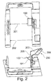
- Fig. 2 is a view of a door aperture of a transport means, with an open door, when viewed from inside the cabin of the transport means, and a view of this arrangement from above.
- the movable carrier arm device 100 When the door is open, the movable carrier arm device 100 is folded out, and is thus in the extended position. This is necessary, for example, in the case of evacuation, when a type "C" exit must be provided. This may be the case, for example, when a single-track emergency slide is used, in order to prevent an excessive number of passengers from using the emergency slide at the same time.
- the effectively usable door aperture width is approximately 86 cm (34 inches) in the region of the carrier arm arrangement (see arrow 201). In the regions below and above (see arrow 202), the door aperture width corresponds to the width of a so-called type "A" exit.
- the lateral surface 205 of the carrier arm cover 203 extends in the region of the carrier arm device 100 perpendicularly to the surface of the outer wall of the transport means so that, when the door is open, there is thereby no narrowing, or at least no substantial narrowing, of the door aperture width.
- the covering flap 101 of the movable carrier arm device 100 has an angle of approximately 60 or 70 degrees with respect to the surface 205 of the carrier arm cover so that it protrudes into the aperture.
- the carrier arm cover 203 is constructed to partially cover the carrier arm 206 of the carrier arm arrangement 200 and can be replaced, if necessary. This may be advantageous, for example, in the case of converting from a single-track emergency slide to a dual-track emergency slide.
- Fig. 3 shows two illustrations of the arrangement of Fig. 2 with the movable carrier arm device 100 in a retracted position.
- the movable carrier arm device is located in the folded-in state. Consequently, substantially the entire door width is available for passengers to embark and disembark.
- the surface of the carrier arm device 100 protrudes only insignificantly, for example, by approximately 2.5 cm from the plane of the carrier arm cover 203 so that an effective door aperture width 301 of approximately 104 cm (41 inches) is produced at the height of the carrier arm arrangement.
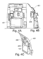
- Fig. 4A shows the door region when viewed from inside the passenger cabin with the door 401 closed.
- the carrier arm arrangement protrudes into the cabin by a relatively small extent.
- the standard component carrier arm cover (so-called “hinge arm cover”) can be slightly adapted, for example, by a recess being provided.
- the movable carrier arm device (also referred to as a “foldable hinge arm device”) is mounted on the carrier arm of this door.
- the basic position is the folded-in state (see Fig. 1A ).
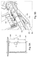
- Fig. 5A shows a door frame structure 505 having a door 401 and a carrier arm arrangement which is fitted thereto.
- Fig. 5B is a sectional illustration through the carrier arm arrangement of the door 401, which is shown in Fig. 5A .
- the covering flap 101 which is constructed in the form of a front element, is raised by means of a frame-side, optionally telescopic pressure pin 501. This operation can also be seen in Fig. 1B .
- the pressure pin 501 is independently actuated by the door moving closer when it is pivoted open and during its associated movement in the direction of the door frame structure since it strikes the door frame structure 505 when the door pivots open (see Fig. 5B ).
- the pressure pin 501 lifts the covering flap of the carrier arm device so far that the self-closing dead centre position is exceeded and the flap is automatically further deployed into the opened end position (see Fig. 1C ), for example, by means of clamping or torsional spring force.
- an actuation hook which releases the covering flap 101 by means of a rotational movement when the door is opened and optionally presses it over the dead centre position.
- the covering flap 101 may also be pretensioned from the start in such a manner that a release of the front element is sufficient to enable automatic opening.
- the carrier arm device can absorb loads, for example, of 2250 Newton, which may occur in the event of an emergency evacuation, and direct them into the structure.
- the rotational movement of the covering flap 101 is indicated by the arrow 502 in Fig. 5B .
- An advantage of the carrier arm arrangement is that, in the fully automated embodiment, the covering flap 101 springs open only in the very rare case of an emergency opening of the door and, in the semi-automated variant, there is the possibility of manually folding in again the flap 101 which is deployed after a "normal” door opening in order to expand the aperture region from 34 inches, for example, to 41 inches. In spite of a type "C" exit, almost the entire width of the type "A" door cutout can consequently be used.
- the covering flap 101 of the carrier arm device may also be provision for the covering flap 101 of the carrier arm device to finish flush with the surface of the carrier arm cover 203 so that in this portion the entire width can be used by the passengers when the carrier arm arrangement is folded in.
- the folding open of the carrier arm device 100 may be carried out independently and not manually, either in a fully automated manner only with an armed emergency slide or in a semi-automated manner each time the door opens normally.
- the folding-in occurs manually in the semi-automated variant. In the fully automated variant, folding-in of the covering flap 101 is not necessary since the flap 101 remains closed other than in the rare case of an evacuation.
- the foldable carrier arm device can be produced with a slightly modified (cutout) standard cover for the type "A" exit.
- the foldable carrier arm device can be placed on the cover and can be screwed to the carrier arm.
- Fig. 6 shows an aircraft 600 according to an embodiment of the invention which has a plurality of doors 401 with the above-described carrier arm arrangements.
Abstract
Description
- This application claims the benefit of the filing date of German Patent Application No.
10 2011 109 652.7 filed August 5, 2011 and of United States Provisional Patent Application No.61/515,654 filed August 5, 2011 - The invention relates to the external doors of transport means. In particular, the invention relates to a carrier arm arrangement for a door of a transport means, a door having a carrier arm arrangement and a transport means having a door.
- Doors of transport means may be connected to the carrying structure of the transport means by means of appropriate hinges or carrier arms (also called hinge arms). In the case of external doors of aircraft, the door may be connected to the carrying structure or the door frame of the cabin by means of a single carrier arm arrangement.
- In the event of evacuation, when a single-track emergency slide is used, it may be specified that the width of the door aperture should not exceed a fixed maximum dimension. For example, the number of passengers who use the emergency slide per unit of time can thereby be kept below a specific value. The related maximum dimension provided for the door aperture width may in this instance be approximately 86 cm (more precisely: 34 inches). This is also referred to in this context as a type "C" aperture width.
- When a dual-track emergency slide is used, however, the door aperture width may be larger. Depending on the emergency slide to be used, various door aperture widths may accordingly be provided.
-
DE 10 2009 019 434 A1 andUS 2010/0276543 A1 disclose aircraft doors. - An object of the invention is to provide a transport means which enables the flexible use of various emergency slides.
- This object is achieved by the features of the independent claims. Developments of the invention result from the sub-claims.
- The features described below may be implemented both in the carrier arm arrangement and in the door and the transport means, and vice versa.
- According to an embodiment of the invention, a carrier arm arrangement (i.e. hinge arm assembly) for a door of a transport means is specified and has a carrier arm (i.e. hinge arm) for retaining and supporting the door. Furthermore, a movable carrier arm device (i.e. hinge arm device) is provided which is constructed to assume a retracted position and an extended position. The carrier arm device is constructed to reduce a width of a door aperture when the door is opened when the movable carrier arm device is moved from the retracted position to the extended position.
- That is to say, the carrier arm arrangement having the carrier arm device, when the door is folded open and when the carrier arm device is in a retracted position, protrudes to a lesser extent into the door aperture than when the carrier arm device is in an extended position. It is not necessary to provide structurally different door cutouts dependent on whether a dual-track or a single-track emergency slide is used.
- Using the invention, it is consequently possible to provide a transport means which has door cutouts which are structurally as large as possible. The required aperture width can be adapted with little complexity depending on the configuration requirement.
- The movable carrier arm device may be provided in this instance as a retrofittable, modular component which can be retrofitted without having to carry out complex structural modifications to a carrier arm which is already installed.
- In this manner, it is possible to convert the carrier arm arrangement from a configuration which is provided for use with dual-track emergency slide operation to a configuration which is provided for use with single-track emergency slide operation by retrofitting the movable carrier arm device.
- In the first instance mentioned of a dual-track emergency slide, the movable carrier arm device is not required. In this instance, the carrier arm may be provided with a standard cover which has no recess for the carrier arm device.
- In particular, the holes, etc., necessary for the subsequent installation of the movable carrier arm device may already be provided in the carrier arm so that retrofitting can be carried out without significant complexity.
- According to an embodiment of the invention, the movable carrier arm arrangement covers the recessed region of the standard cover. As an alternative to this carrier arm cover, a different carrier arm cover without any recess can be provided (for example, in the case of a dual-track emergency slide).
- According to another embodiment of the invention, the carrier arm arrangement is constructed to reduce the width of the door aperture, from approximately 100% to approximately 80% by the movable carrier arm device being extended.
- That is to say, by extending (for example, folding out) the movable carrier arm device, the effectively usable door aperture width can be significantly reduced, for example, from a type "A" exit (41 inches, that is, approximately 104 cm) to a type "C" exit (approximately 34 inches, that is, approximately 86 cm).
- According to another embodiment of the invention, the movable carrier arm device is secured to the carrier arm cover. Alternatively or in addition, the movable carrier arm device may also be secured to the carrier arm itself.
- According to another embodiment of the invention, the movable carrier arm device is constructed to automatically assume the extended position when the door is opened (if it was previously in the retracted position).
- That is to say, the carrier arm device always folds out from the carrier arm when the door is opened. After the door is opened, it can then be moved, for example manually, back into the folded-in, retracted position.
- According to another embodiment of the invention, the movable carrier arm device is constructed to only automatically assume the extended position when the door is opened in the event of an emergency which requires the use of an emergency slide.
- This may be achieved, for example, by the arming of the emergency slide, which is carried out, for example, before the aircraft takes off, being coupled to the movable carrier arm device or the actuation mechanism thereof, so that the arming of the emergency slide also brings about arming of the actuation mechanism. If the door is then opened without the emergency slide being disarmed beforehand, the carrier arm device automatically folds out so that the door aperture is automatically reduced.
- However, if the emergency slide is disarmed before the door is opened, as is the case when the door is opened under normal circumstances, the actuation mechanism of the carrier arm device is disarmed at the same time so that it does not fold out when the door is opened.
- That is to say, the carrier arm device only moves from the retracted position to the extended position when the door is opened in the event of an emergency.
- For automated or partially automated actuation of the carrier arm device, there may be provided, for example, a corresponding pin mechanism which strikes the door frame when the door is opened and consequently brings about opening of the flap of the carrier arm device. The movement of the carrier arm device from the retracted state into the extended state is therefore actuated by the door approaching the door frame (when the door is opened). Alternatively or in addition to such a pressure pin mechanism, an actuation hook mechanism may also be provided. In this instance, the actuation may be carried out by means of a rotational movement of the hook, whereas this is carried out by means of a linear movement in the case of the pressure pin.
- According to another embodiment of the invention, a door for a transport means is specified having a carrier arm arrangement described above and below.
- According to another embodiment of the invention, the door and the carrier arm arrangement correspond to each other in such a manner that, owing to a movement of the carrier arm device into the extended position, the width of the door aperture with the door open is reduced from approximately 104 cm (41 inches) to approximately 86 cm (34 inches).
- According to another embodiment of the invention, there is set out a transport means is specified having a door which is described above and below. The transport means is, for example, an aircraft, such as a helicopter, airship or aeroplane, a road vehicle such as, for example, an automobile, lorry or bus, a rail vehicle or a watercraft.
- Embodiments of the invention are described below with reference to the figures.
-
-
Figs. 1A to 1F show various states of a carrier arm arrangement according to an embodiment of the invention, -
Fig. 2 shows the type "C" door region of an aircraft in the event of evacuation according to an embodiment of the invention, when viewed from inside and from above, -
Fig. 3 shows the interior region ofFig. 2 , with normal door opening, -
Fig. 4A shows the interior region ofFig. 2 , with the door closed, -
Figs. 4B and 4C are two illustrations of the door ofFig. 4A , -
Fig. 5A shows a door frame with a door fitted therein according to an embodiment of the invention, -
Fig. 5B is a section through the door ofFig. 5A along the line of section A-A, -
Fig. 6 shows an aircraft according to an embodiment of the invention. - The illustrations in the figures are schematic and are not to scale.
- In the following description of the figures, if the same reference numerals are used in different figures, they refer to identical or similar elements. However, elements which are the same or similar may also be referred to using different reference numerals.
-
Figs. 1A to 1F show various states of the movablecarrier arm device 100 in combination with acarrier arm cover 203. - In
Fig. 1A , the movablecarrier arm device 100 is in the retracted position so that only thecovering flap 101 of the carrier arm device can be seen. In this state, thecovering flap 101 may protrude slightly from the surface of thecarrier arm cover 203. There may also be provision for the surface of thecovering flap 101 of the movablecarrier arm device 100 to be arranged substantially in the same plane as the surface of the corresponding region of thecarrier arm cover 203, in which region thecovering flap 101 is embedded. - The
carrier arm cover 203 may be a standard component which has a recess for receiving the movablecarrier arm device 100. - By applying a compression force to the
covering flap 101 from below, that is to say, from inside the carrier arm arrangement (see arrow 103), the opening operation of the carrier arm device can be triggered (seeFig.1B ). This compression force may be brought about, for example, by an actuation pin or an actuation hook, which presses from the inner side against the rear side of thecovering flap 101 when the door is opened. The covering flap may also be mechanically pretensioned so that it automatically springs open by a lock being released when the door is opened. -
Fig. 1C shows the extended position of the movable carrier arm device. This position is achieved by thelower edge 112 of a plate-like support element 104 being moved in the direction of thearrow 113 along therails rails covering flap 101 in the folded-in state (seeFig. 1A ). In the folded-out state, the angle between the tworails covering flap 101 is, for example, between 30 and 60 degrees, for example, approximately 40 degrees. However, the angle may also be up to 90 degrees or more. - In order to enable the pivot movement of the
covering flap 101, this element is rotatably mounted by means of anaxial suspension 109. Theaxial suspension 109 is located in this instance at the side of thecovering flap 101 which is, for example, rectangular, which side faces the carrier arm in the folded-open state, whereas the securing of thesupport element 104 to theflap 101 is at the opposing side. - The opening operation can be supported by means of corresponding resilient elements which extend along the
rails 107, 108 (seereference numeral 510 inFig. 5B ). The supporting force begins, for example, after a minimum opening angle is exceeded. - In this manner, it is possible, by applying a minimum compression force to the inner side of the
covering flap 101 when the minimum opening angle is exceeded, for automatic additional opening of thecovering flap 101 to be carried out so that it moves into the extended position. -
Figs. 1D to 1F show the reverse operation, in which the movablecarrier arm device 100 is moved from the extended position (seeFig. 1D ) by applying a compression force to the plate-like support element 104 (see arrow 110) into an intermediate position (seeFig. 1E ) and subsequently by applying a compression force to the outer side of the covering flap 101 (seearrow 111 inFig. 1E ) into the retracted position (see Fig. IF). - This operation can be carried out manually by a crew member when the door is opened.
- The movement of the carrier arm device from the folded-in position into the folded-out extended position can be actuated, depending on the embodiment, by means of a corresponding mechanism either in a semi-automated manner, that is to say, each time the door is opened, or in a fully automated manner, that is to say, only when the emergency slide has been "armed" beforehand.
- In the event of evacuation, the aperture width of the door in an equipment variant with a single-track emergency slide can be limited to the type "C" (34 inches, that is to say, approximately 86 cm).
- However, during normal operation of this door, the movable carrier arm device allows a door aperture width ("clear passageway") of approximately 104 cm (41 inches). In this instance, substantially the entire width of a so-called type "A" exit is accordingly available (with the exception of a projection of the carrier arm device beyond the carrier arm cover). This provides additional comfort for the air passenger when embarking and disembarking. An increase in comfort for the cabin crew can also thereby be achieved since, even when the door is closed, more space is available in the door region during flight operation. Consequently, the catering section can also benefit from the increased door aperture width.
-
Fig. 2 is a view of a door aperture of a transport means, with an open door, when viewed from inside the cabin of the transport means, and a view of this arrangement from above. - When the door is open, the movable
carrier arm device 100 is folded out, and is thus in the extended position. This is necessary, for example, in the case of evacuation, when a type "C" exit must be provided. This may be the case, for example, when a single-track emergency slide is used, in order to prevent an excessive number of passengers from using the emergency slide at the same time. - In this instance, the effectively usable door aperture width is approximately 86 cm (34 inches) in the region of the carrier arm arrangement (see arrow 201). In the regions below and above (see arrow 202), the door aperture width corresponds to the width of a so-called type "A" exit.
- As can be seen from the plan view of
Fig. 2 , thelateral surface 205 of thecarrier arm cover 203 extends in the region of thecarrier arm device 100 perpendicularly to the surface of the outer wall of the transport means so that, when the door is open, there is thereby no narrowing, or at least no substantial narrowing, of the door aperture width. - However, the
covering flap 101 of the movablecarrier arm device 100 has an angle of approximately 60 or 70 degrees with respect to thesurface 205 of the carrier arm cover so that it protrudes into the aperture. - The
carrier arm cover 203 is constructed to partially cover thecarrier arm 206 of thecarrier arm arrangement 200 and can be replaced, if necessary. This may be advantageous, for example, in the case of converting from a single-track emergency slide to a dual-track emergency slide. -
Fig. 3 shows two illustrations of the arrangement ofFig. 2 with the movablecarrier arm device 100 in a retracted position. The movable carrier arm device is located in the folded-in state. Consequently, substantially the entire door width is available for passengers to embark and disembark. - With the door open, the surface of the
carrier arm device 100 protrudes only insignificantly, for example, by approximately 2.5 cm from the plane of thecarrier arm cover 203 so that an effectivedoor aperture width 301 of approximately 104 cm (41 inches) is produced at the height of the carrier arm arrangement. -
Fig. 4A shows the door region when viewed from inside the passenger cabin with thedoor 401 closed. In particular, it can be seen that the carrier arm arrangement protrudes into the cabin by a relatively small extent. - With the customer option of a type "C" exit, the standard component carrier arm cover (so-called "hinge arm cover") can be slightly adapted, for example, by a recess being provided. In addition, the movable carrier arm device (also referred to as a "foldable hinge arm device") is mounted on the carrier arm of this door.
- The basic position is the folded-in state (see
Fig. 1A ). -
Fig. 5A shows adoor frame structure 505 having adoor 401 and a carrier arm arrangement which is fitted thereto. -
Fig. 5B is a sectional illustration through the carrier arm arrangement of thedoor 401, which is shown inFig. 5A . Either each time the door is opened or only when the emergency slide is actuated, for example, by means of a coupling with the actuation lever for arming the emergency slide (so-called slide arming lever), thecovering flap 101, which is constructed in the form of a front element, is raised by means of a frame-side, optionallytelescopic pressure pin 501. This operation can also be seen inFig. 1B . - The
pressure pin 501 is independently actuated by the door moving closer when it is pivoted open and during its associated movement in the direction of the door frame structure since it strikes thedoor frame structure 505 when the door pivots open (seeFig. 5B ). - The
pressure pin 501 lifts the covering flap of the carrier arm device so far that the self-closing dead centre position is exceeded and the flap is automatically further deployed into the opened end position (seeFig. 1C ), for example, by means of clamping or torsional spring force. - Alternatively or in addition to the
pressure pin 501, there may also be provided, for example, an actuation hook which releases thecovering flap 101 by means of a rotational movement when the door is opened and optionally presses it over the dead centre position. There may also be provision for thecovering flap 101 to be pretensioned from the start in such a manner that a release of the front element is sufficient to enable automatic opening. - In the extended position, the carrier arm device can absorb loads, for example, of 2250 Newton, which may occur in the event of an emergency evacuation, and direct them into the structure.
- The rotational movement of the
covering flap 101 is indicated by thearrow 502 inFig. 5B . - An advantage of the carrier arm arrangement is that, in the fully automated embodiment, the
covering flap 101 springs open only in the very rare case of an emergency opening of the door and, in the semi-automated variant, there is the possibility of manually folding in again theflap 101 which is deployed after a "normal" door opening in order to expand the aperture region from 34 inches, for example, to 41 inches. In spite of a type "C" exit, almost the entire width of the type "A" door cutout can consequently be used. - In particular, there may also be provision for the
covering flap 101 of the carrier arm device to finish flush with the surface of thecarrier arm cover 203 so that in this portion the entire width can be used by the passengers when the carrier arm arrangement is folded in. - Consequently, the provision of a constant structural cutout dimension for each door in the aircraft is possible, regardless of whether a single-track or a dual-track emergency slide is intended to be used, or whether a type "A" exit or a type "C" exit is provided.
- The
carrier arm arrangement 200 is, for example, used only with the customer-specific equipment option type "C" (= single-track emergency slide). - There may be provision for the folding open of the
carrier arm device 100 always to be carried out independently and not manually, either in a fully automated manner only with an armed emergency slide or in a semi-automated manner each time the door opens normally. - The folding-in occurs manually in the semi-automated variant. In the fully automated variant, folding-in of the
covering flap 101 is not necessary since theflap 101 remains closed other than in the rare case of an evacuation. - The foldable carrier arm device can be produced with a slightly modified (cutout) standard cover for the type "A" exit.
- As an "attachment solution", the foldable carrier arm device can be placed on the cover and can be screwed to the carrier arm.
-
Fig. 6 shows anaircraft 600 according to an embodiment of the invention which has a plurality ofdoors 401 with the above-described carrier arm arrangements. - In addition, it should be noted that the terms "comprising" and "having" do not exclude any other elements or steps and "a" or "an" does not exclude a plurality. It should further be noted that features or steps which have been described with reference to one of the above embodiments can also be used in combination with other features or steps of other embodiments described above. Reference numerals in the claims are not intended to be considered to be a limitation.
Claims (11)
- Carrier arm arrangement (200) for a door (401) of a transport means (600), the carrier arm arrangement comprising:a carrier arm (206) for retaining and supporting the door;a movable carrier arm device (100) which is adapted to assume a retracted position and an extended position;wherein the carrier arm arrangement is adapted to reduce a width of a door aperture when the door is in its open position, when the movable carrier arm device is moved from the retracted position to the extended position.
- Carrier arm arrangement according to claim 1, further comprising:a carrier arm cover (203) for covering a region of the carrier arm (206);wherein the carrier arm cover (203) has a recess for receiving a portion of the movable carrier arm device (100).
- Carrier arm arrangement according to either of the preceding claims, wherein the carrier arm arrangement is adapted to reduce the width of the door aperture to approximately 80% by the movable carrier arm device (100) being extended.
- Carrier arm arrangement according to either claim 2 or claim 3,
wherein the movable carrier arm device (100) is secured to at least one of the carrier arm cover or carrier arm. - Carrier arm arrangement according to any one of the preceding claims, wherein the movable carrier arm device (100), starting from the retracted position, is adapted to automatically assume the extended position when the door is opened.
- Carrier arm arrangement according to any one of claims 1 to 4,
wherein the movable carrier arm device (100) is adapted to only automatically assume the extended position when the door is opened in the event of an emergency, which emergency requires the use of an emergency slide. - Carrier arm arrangement according to claim 6,
wherein the movable carrier arm device (100) is adapted to only automatically assume the extended position when the door is opened in the event of an emergency, which emergency requires the use of a single-track emergency slide. - Door for a transport means comprising:a carrier arm arrangement (200) according to any one of claims 1 to 7.
- Door according to claim 8,
wherein the carrier arm arrangement (200) is adapted to reduce the width of the door aperture when the door is opened. - Transport means (600) having a door (401) according to either claim 8 or claim 9.
- Transport means according to claim 10,
wherein the transport means is an aircraft (600).
Applications Claiming Priority (2)
| Application Number | Priority Date | Filing Date | Title |
|---|---|---|---|
| US201161515654P | 2011-08-05 | 2011-08-05 | |
| DE102011109652A DE102011109652A1 (en) | 2011-08-05 | 2011-08-05 | Support arm arrangement, door and means of transport |
Publications (2)
| Publication Number | Publication Date |
|---|---|
| EP2554473A2 true EP2554473A2 (en) | 2013-02-06 |
| EP2554473A3 EP2554473A3 (en) | 2017-06-28 |
Family
ID=46785223
Family Applications (1)
| Application Number | Title | Priority Date | Filing Date |
|---|---|---|---|
| EP12177825.2A Withdrawn EP2554473A3 (en) | 2011-08-05 | 2012-07-25 | Carrier arm arrangement, door and transport means |
Country Status (3)
| Country | Link |
|---|---|
| US (1) | US9132905B2 (en) |
| EP (1) | EP2554473A3 (en) |
| DE (1) | DE102011109652A1 (en) |
Families Citing this family (2)
| Publication number | Priority date | Publication date | Assignee | Title |
|---|---|---|---|---|
| AT515354A1 (en) | 2014-01-21 | 2015-08-15 | Facc Ag | Device for opening an aircraft door |
| USD912603S1 (en) * | 2019-05-24 | 2021-03-09 | Alakai Technologies Corporation | Set of aircraft clamshell rear doors |
Citations (1)
| Publication number | Priority date | Publication date | Assignee | Title |
|---|---|---|---|---|
| US20100276543A1 (en) | 2009-04-29 | 2010-11-04 | Airbus Operations Gmbh | Aircraft door and a method for the manufacture of an aircraft door of this type |
Family Cites Families (10)
| Publication number | Priority date | Publication date | Assignee | Title |
|---|---|---|---|---|
| GB868390A (en) * | 1958-07-04 | 1961-05-17 | Vickers Aircraft Holdings Ltd | Improvements in doors for pressurized fuselages of aircraft |
| US3791073A (en) * | 1972-04-28 | 1974-02-12 | Boeing Co | Aircraft door with moving hinge line |
| US4199120A (en) * | 1977-11-01 | 1980-04-22 | The Boeing Company | Folding, plug type aircraft door |
| FR2548623B1 (en) * | 1983-07-08 | 1985-10-11 | Aerospatiale | SAFETY DEVICE FOR OPENING AN AIRCRAFT DOOR OPENING OUTSIDE IN THE EVENT OF AN OVERPRESSURE INSIDE THIS AIRCRAFT AND DOOR THUS EQUIPPED |
| FR2576217B1 (en) * | 1985-01-24 | 1987-03-06 | Aerospatiale | MECHANISM FOR THE AUTOMATIC OPERATION OF A RESCUE DEVICE WHEN OPENING A DOOR |
| US5156359A (en) * | 1991-06-13 | 1992-10-20 | The Boeing Company | Handle assembly for an aircraft door or the like |
| DE10132361C1 (en) * | 2001-07-04 | 2002-11-07 | Eurocopter Deutschland | Aeroplane passenger door, for accessing passenger cabin, has lifting mechanism for opening passenger door cooperating with lowering safety device |
| DE102008030696A1 (en) * | 2008-07-01 | 2010-01-14 | Eurocopter Deutschland Gmbh | Airplane door with support arm arrangement |
| US8403265B2 (en) * | 2009-09-01 | 2013-03-26 | Textron Innovations, Inc. | Aircraft cabin door pressure vent system |
| US9187176B2 (en) * | 2011-09-20 | 2015-11-17 | The Boeing Company | Dual boarding system for aircraft |
-
2011
- 2011-08-05 DE DE102011109652A patent/DE102011109652A1/en not_active Ceased
-
2012
- 2012-07-25 EP EP12177825.2A patent/EP2554473A3/en not_active Withdrawn
- 2012-07-30 US US13/561,167 patent/US9132905B2/en active Active
Patent Citations (2)
| Publication number | Priority date | Publication date | Assignee | Title |
|---|---|---|---|---|
| US20100276543A1 (en) | 2009-04-29 | 2010-11-04 | Airbus Operations Gmbh | Aircraft door and a method for the manufacture of an aircraft door of this type |
| DE102009019434A1 (en) | 2009-04-29 | 2010-11-11 | Airbus Operations Gmbh | Aircraft door and method of making such an aircraft door |
Also Published As
| Publication number | Publication date |
|---|---|
| US9132905B2 (en) | 2015-09-15 |
| EP2554473A3 (en) | 2017-06-28 |
| DE102011109652A1 (en) | 2013-02-07 |
| US20130043349A1 (en) | 2013-02-21 |
Similar Documents
| Publication | Publication Date | Title |
|---|---|---|
| US11851186B2 (en) | Mini suite emergency egress solutions | |
| KR102019238B1 (en) | A rotary wing aircraft with a sliding element, in particular a sliding door or a sliding window | |
| EP3323709B1 (en) | An actuatable emergency exit door and an aircraft or space craft with a pressurized cabin having such an actuatable emergency exit door | |
| US9038964B2 (en) | Control surface assembly | |
| EP2878534B1 (en) | Emergency gravity free-fall deployment systems for retractable aircraft landing gear assemblies | |
| US8833840B2 (en) | Vehicle panel provided with a movable window, and an associated vehicle | |
| US10974834B2 (en) | Separable vehicle cabin privacy partition assemblies which allow for emergency egress | |
| US20030141415A1 (en) | Ejectable door for aircraft | |
| CN105857566B (en) | Aircraft cockpit equipped with a safety vent | |
| US11274484B2 (en) | Door system with a deceleration mechanism | |
| US10871013B2 (en) | Load transfer interface for a vehicle door, in particular for an aircraft cabin door | |
| EP2554473A2 (en) | Carrier arm arrangement, door and transport means | |
| CN112272623B (en) | Assembly for a roof cover and roof for a motor vehicle | |
| EP3967596B1 (en) | Airstair system with deployable upper step | |
| US20170210460A1 (en) | Aircraft door with retractable header |
Legal Events
| Date | Code | Title | Description |
|---|---|---|---|
| STAA | Information on the status of an ep patent application or granted ep patent |
Free format text: STATUS: REQUEST FOR EXAMINATION WAS MADE |
|
| PUAI | Public reference made under article 153(3) epc to a published international application that has entered the european phase |
Free format text: ORIGINAL CODE: 0009012 |
|
| 17P | Request for examination filed |
Effective date: 20120725 |
|
| AK | Designated contracting states |
Kind code of ref document: A2 Designated state(s): AL AT BE BG CH CY CZ DE DK EE ES FI FR GB GR HR HU IE IS IT LI LT LU LV MC MK MT NL NO PL PT RO RS SE SI SK SM TR |
|
| AX | Request for extension of the european patent |
Extension state: BA ME |
|
| PUAL | Search report despatched |
Free format text: ORIGINAL CODE: 0009013 |
|
| AK | Designated contracting states |
Kind code of ref document: A3 Designated state(s): AL AT BE BG CH CY CZ DE DK EE ES FI FR GB GR HR HU IE IS IT LI LT LU LV MC MK MT NL NO PL PT RO RS SE SI SK SM TR |
|
| AX | Request for extension of the european patent |
Extension state: BA ME |
|
| RIC1 | Information provided on ipc code assigned before grant |
Ipc: B64C 1/14 20060101AFI20170522BHEP |
|
| STAA | Information on the status of an ep patent application or granted ep patent |
Free format text: STATUS: REQUEST FOR EXAMINATION WAS MADE |
|
| 18D | Application deemed to be withdrawn |
Effective date: 20180103 |