EP2554418A1 - Car with a sun roof provided with a containing tank of the rear window - Google Patents
Car with a sun roof provided with a containing tank of the rear window Download PDFInfo
- Publication number
- EP2554418A1 EP2554418A1 EP12178919A EP12178919A EP2554418A1 EP 2554418 A1 EP2554418 A1 EP 2554418A1 EP 12178919 A EP12178919 A EP 12178919A EP 12178919 A EP12178919 A EP 12178919A EP 2554418 A1 EP2554418 A1 EP 2554418A1
- Authority
- EP
- European Patent Office
- Prior art keywords
- car
- roof
- rear window
- external
- frame
- Prior art date
- Legal status (The legal status is an assumption and is not a legal conclusion. Google has not performed a legal analysis and makes no representation as to the accuracy of the status listed.)
- Granted
Links
- 238000007789 sealing Methods 0.000 claims description 46
- 239000011796 hollow space material Substances 0.000 claims description 7
- 238000004891 communication Methods 0.000 claims description 2
- 210000000056 organ Anatomy 0.000 claims 2
- 230000008901 benefit Effects 0.000 description 4
- 230000007246 mechanism Effects 0.000 description 4
- XLYOFNOQVPJJNP-UHFFFAOYSA-N water Substances O XLYOFNOQVPJJNP-UHFFFAOYSA-N 0.000 description 4
- 230000009471 action Effects 0.000 description 3
- 238000009825 accumulation Methods 0.000 description 1
- 238000004873 anchoring Methods 0.000 description 1
- 230000004888 barrier function Effects 0.000 description 1
- 230000000295 complement effect Effects 0.000 description 1
- 239000011521 glass Substances 0.000 description 1
- 230000008595 infiltration Effects 0.000 description 1
- 238000001764 infiltration Methods 0.000 description 1
- 238000009413 insulation Methods 0.000 description 1
- 239000002184 metal Substances 0.000 description 1
- 238000010257 thawing Methods 0.000 description 1
- 238000009423 ventilation Methods 0.000 description 1
Images


Classifications
-
- B—PERFORMING OPERATIONS; TRANSPORTING
- B60—VEHICLES IN GENERAL
- B60J—WINDOWS, WINDSCREENS, NON-FIXED ROOFS, DOORS, OR SIMILAR DEVICES FOR VEHICLES; REMOVABLE EXTERNAL PROTECTIVE COVERINGS SPECIALLY ADAPTED FOR VEHICLES
- B60J7/00—Non-fixed roofs; Roofs with movable panels, e.g. rotary sunroofs
- B60J7/22—Wind deflectors for open roofs
- B60J7/223—Wind deflectors for open roofs specially adapted for convertible cars
-
- B—PERFORMING OPERATIONS; TRANSPORTING
- B60—VEHICLES IN GENERAL
- B60J—WINDOWS, WINDSCREENS, NON-FIXED ROOFS, DOORS, OR SIMILAR DEVICES FOR VEHICLES; REMOVABLE EXTERNAL PROTECTIVE COVERINGS SPECIALLY ADAPTED FOR VEHICLES
- B60J1/00—Windows; Windscreens; Accessories therefor
- B60J1/18—Windows; Windscreens; Accessories therefor arranged at the vehicle rear
- B60J1/1807—Windows; Windscreens; Accessories therefor arranged at the vehicle rear movable for vehicles with convertible top
- B60J1/1823—Windows; Windscreens; Accessories therefor arranged at the vehicle rear movable for vehicles with convertible top adjustable relative to hard- or soft-top, e.g. pivotable
- B60J1/183—Windows; Windscreens; Accessories therefor arranged at the vehicle rear movable for vehicles with convertible top adjustable relative to hard- or soft-top, e.g. pivotable slidable
-
- B—PERFORMING OPERATIONS; TRANSPORTING
- B60—VEHICLES IN GENERAL
- B60J—WINDOWS, WINDSCREENS, NON-FIXED ROOFS, DOORS, OR SIMILAR DEVICES FOR VEHICLES; REMOVABLE EXTERNAL PROTECTIVE COVERINGS SPECIALLY ADAPTED FOR VEHICLES
- B60J10/00—Sealing arrangements
- B60J10/20—Sealing arrangements characterised by the shape
- B60J10/25—Sealing arrangements characterised by the shape characterised by water drainage means
-
- B—PERFORMING OPERATIONS; TRANSPORTING
- B60—VEHICLES IN GENERAL
- B60J—WINDOWS, WINDSCREENS, NON-FIXED ROOFS, DOORS, OR SIMILAR DEVICES FOR VEHICLES; REMOVABLE EXTERNAL PROTECTIVE COVERINGS SPECIALLY ADAPTED FOR VEHICLES
- B60J10/00—Sealing arrangements
- B60J10/90—Sealing arrangements specially adapted for non-fixed roofs, e.g. foldable roofs or removable hard-tops
-
- B—PERFORMING OPERATIONS; TRANSPORTING
- B60—VEHICLES IN GENERAL
- B60J—WINDOWS, WINDSCREENS, NON-FIXED ROOFS, DOORS, OR SIMILAR DEVICES FOR VEHICLES; REMOVABLE EXTERNAL PROTECTIVE COVERINGS SPECIALLY ADAPTED FOR VEHICLES
- B60J7/00—Non-fixed roofs; Roofs with movable panels, e.g. rotary sunroofs
- B60J7/0084—Water draining for non-fixed roofs or roof panels
-
- B—PERFORMING OPERATIONS; TRANSPORTING
- B60—VEHICLES IN GENERAL
- B60J—WINDOWS, WINDSCREENS, NON-FIXED ROOFS, DOORS, OR SIMILAR DEVICES FOR VEHICLES; REMOVABLE EXTERNAL PROTECTIVE COVERINGS SPECIALLY ADAPTED FOR VEHICLES
- B60J7/00—Non-fixed roofs; Roofs with movable panels, e.g. rotary sunroofs
- B60J7/08—Non-fixed roofs; Roofs with movable panels, e.g. rotary sunroofs of non-sliding type, i.e. movable or removable roofs or panels, e.g. let-down tops or roofs capable of being easily detached or of assuming a collapsed or inoperative position
- B60J7/12—Non-fixed roofs; Roofs with movable panels, e.g. rotary sunroofs of non-sliding type, i.e. movable or removable roofs or panels, e.g. let-down tops or roofs capable of being easily detached or of assuming a collapsed or inoperative position foldable; Tensioning mechanisms therefor, e.g. struts
- B60J7/14—Non-fixed roofs; Roofs with movable panels, e.g. rotary sunroofs of non-sliding type, i.e. movable or removable roofs or panels, e.g. let-down tops or roofs capable of being easily detached or of assuming a collapsed or inoperative position foldable; Tensioning mechanisms therefor, e.g. struts with a plurality of rigid plate-like elements or rigid non plate-like elements, e.g. with non-slidable, but pivotable or foldable movement
- B60J7/143—Non-fixed roofs; Roofs with movable panels, e.g. rotary sunroofs of non-sliding type, i.e. movable or removable roofs or panels, e.g. let-down tops or roofs capable of being easily detached or of assuming a collapsed or inoperative position foldable; Tensioning mechanisms therefor, e.g. struts with a plurality of rigid plate-like elements or rigid non plate-like elements, e.g. with non-slidable, but pivotable or foldable movement for covering the passenger compartment
- B60J7/146—Non-fixed roofs; Roofs with movable panels, e.g. rotary sunroofs of non-sliding type, i.e. movable or removable roofs or panels, e.g. let-down tops or roofs capable of being easily detached or of assuming a collapsed or inoperative position foldable; Tensioning mechanisms therefor, e.g. struts with a plurality of rigid plate-like elements or rigid non plate-like elements, e.g. with non-slidable, but pivotable or foldable movement for covering the passenger compartment all elements being folded in same orientation and stacked fashion
-
- B—PERFORMING OPERATIONS; TRANSPORTING
- B60—VEHICLES IN GENERAL
- B60J—WINDOWS, WINDSCREENS, NON-FIXED ROOFS, DOORS, OR SIMILAR DEVICES FOR VEHICLES; REMOVABLE EXTERNAL PROTECTIVE COVERINGS SPECIALLY ADAPTED FOR VEHICLES
- B60J7/00—Non-fixed roofs; Roofs with movable panels, e.g. rotary sunroofs
- B60J7/20—Vehicle storage compartments for roof parts or for collapsible flexible tops
- B60J7/202—Vehicle storage compartments for roof parts or for collapsible flexible tops being characterised by moveable cover parts for closing the gap between boot lid and rearmost seats
- B60J7/203—Vehicle storage compartments for roof parts or for collapsible flexible tops being characterised by moveable cover parts for closing the gap between boot lid and rearmost seats the cover part comprising cover side flaps
Definitions
- Patent EP1912815B1 describes a car with a sun roof, wherein the frame comprises two fixed vertical posts, which are arranged facing each other on opposite sides of the car at a boundary zone between a passenger compartment and a rear engine compartment.
- the sun roof comprises a pair of rigid roof members, which are mechanically connected to the frame by means of respective connection members arranged at internal walls of the two vertical posts.
- a rear roof member leans against an upper wall of the two vertical posts when the roof is in a closed position (i.e. when the roof closes the top of the passenger compartment of the car).
- roof members 7 and 8 perform an approximately 180° rotation about the rotation axes 11 and 13 with respect to the posts 6 of frame 4, in order to move the sun roof 5 from the closed position to the open position, and vice versa.
Abstract
Description
- The present invention relates to a car with a sun roof.
- Patent
EP1912815B1 describes a car with a sun roof, wherein the frame comprises two fixed vertical posts, which are arranged facing each other on opposite sides of the car at a boundary zone between a passenger compartment and a rear engine compartment. The sun roof comprises a pair of rigid roof members, which are mechanically connected to the frame by means of respective connection members arranged at internal walls of the two vertical posts. A rear roof member leans against an upper wall of the two vertical posts when the roof is in a closed position (i.e. when the roof closes the top of the passenger compartment of the car). - It has been observed that the contact zone between the upper walls of the two vertical posts and the rear roof member is rather critical with respect to water infiltrations, because achieving adequate sealing in this contact zone while keeping a pleasant appearance when the roof is in an open position (i.e. when the roof is folded and arranged in a rear housing) is complex. It is worth noting that pleasant appearance is of the utmost importance in a car with sun roof, because these types of cars are chosen essentially for their appearance; furthermore, the vertical post zone is one of the most evident because it is immediately by the side of the door handles, and thus in the line of sight of occupants getting in and out of the car.
- It is the object of the present invention to provide a sun roof which is free from the above-described drawbacks, and in particular which is easy and cost-effective to be implemented.
- According to the present invention, a car with sun roof is provided as claimed in the appended claims.
- The present invention will now be described with reference to the accompanying drawings, which show a non-limitative embodiment thereof, in which:
-
figure 1 is a diagrammatic perspective view of a car with sun roof provided in accordance with the present invention, in which the sun roof is set in a closed position; -
figure 2 is a partially exploded view of the sun roof of the car infigure 1 ; -
figures 3-7 are a series of diagrammatic side views of the car infigure 1 , during the subsequent steps of opening the sun roof; -
figure 8 is a diagrammatic rear view of a detail of an internal post and of an external post of the frame of the car infigure 1 ; -
figure 9 is a diagrammatic perspective view of a closing body connected to a cover of a housing of roof members of the sun roof of the car infigure 1 ; -
figure 10 is a diagrammatic perspective view of the closing body offigure 8 leaning against a vertical post of the car frame; -
figure 11 is a diagrammatic perspective view of the vertical post infigure 9 without the presence of the closing body infigure 8 ; -
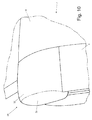
figure 12 is a diagrammatic cross-section view of a support structure of a rear window of the car infigure 1 ; -
figures 13-17 are some diagrammatic perspective views of gaskets of some parts of the sun roof of the car infigure 1 ; and -
figure 18 is an diagrammatic, exploded perspective view of all the gaskets of the car infigure 1 . - In
figure 1 ,numeral 1 indicates as a whole a car having apassenger compartment 2 and anengine compartment 3, which is arranged in a central position behind thepassenger compartment 2 and is closed by a partially transparent opening cover. A frame 4 ofcar 1 supports asun roof 5, which may be set in an open position (shown infigure 6 ), in which thepassenger compartment 2 is open, or in a closed position (shown infigures 1 and3 ) in which theentire passenger compartment 2 is covered by thesun roof 5. - As shown in
figures 1 and2 , in order to support thesun roof 5, frame 4 comprises two externalvertical posts 6, which vertically project from the belt line ofcar 1 and face each other on opposite sides ofcar 1 at a boundary zone between thepassenger compartment 2 and theengine compartment 3. - The
sun roof 5 comprises a pair ofrigid roof members roof members roof members roof member connection arms roof members arm vertical posts 6 and by a portion of frame 4 arranged under theposts 6, and more internally than theposts 6. - In the embodiment shown in the accompanying figures, each
arm 9 is "L"-shaped and has one end rigidly fixed to theroof hinge 7 and an opposite end hinged to frame 4 at apost 6 in order to rotate with respect to the frame 4 itself about ahorizontal rotation axis 11 under the bias of anactuator device 12. Eacharm 10 has a substantially rectilinear shape and has one end rigidly fixed to theroof member 8 and an opposite end hinged to frame 4 at apost 6 in order to rotate with respect the frame 4 itself about ahorizontal rotation axis 13 parallel to and offset with respect to therotation axis 11 under the bias of theactuator device 12. According to a preferred embodiment (not shown),roof member 7 androof member 8 are connected to frame 4 at thepost 6 by means of an articulated quadrilateral so as to perform a rototranslation instead of a simple rotation with respect to the frame 4 itself; in other words, according to a preferred embodiment, the support members ofroof members rotation axes rotation axis 11 and therotation axis 13 are movable, i.e. move in use parallely to themselves. - When the
sun roof 5 is set in the closed position (figures 1 and3 ), the tworoof members sun roof 5 is set in the closed position (figures 1 and3 ), theroof member 7 is arranged in a front position so as to lean the front end thereof in contact with awindscreen 14 ofcar 1 and to arrange the rear end thereof in contact with the front end of theroof member 8; moreover, theroof member 8 is arranged in a rear position so as to arrange the front end thereof in contact with the rear end of theroof element 7 and to arrange the rear end thereof in contact, at the back, with arear window 15 ofcar 1, and laterally with theposts 6 of frame 4. - It is worth noting that the two
roof members sun roof 5 is set in the closed position (figures 1 and3 ). - In
figures 3-7 , it is apparent that theroof members rotation axes posts 6 of frame 4, in order to move thesun roof 5 from the closed position to the open position, and vice versa. - When the
sun roof 5 is set in the open position (figure 7 ), theroof members housing 16, which is obtained above theengine compartment 3 immediately next toposts 6 andrear window 15, and is closed by acover 17 hinged at the back to rotate about ahorizontal rotation axis 18 parallel to therotation axes closing cover 17 is controlled by a servo actuator (not shown) of the electric or hydraulic type.Cover 17 may be hinged to frame 4 by means of simple hinges, or alternativelycover 17 may be connected to frame 4 by means of a pair of articulated quadrilaterals to perform a rototranslation with respect to the frame 4 itself. - Preferably,
cover 17 has a pair offins 19, which are arranged on opposite sides of thecover 17, and which lean, whencover 17 is closed, against the externalvertical posts 6 whencover 17 is in a closed position of thehousing 16. - In
housing 16, the tworoof members roof members housing 16, and inparticular roof member 7 is arranged overroof member 8 in thehousing 16. - In order to take the
sun roof 5 from the closed position (figures 1 and3 ) to the open position (figure 7 ) and vice versa, theactuator device 12 rotates theroof member 7 about therotation axis 11 and rotates theroof member 8 independently from theroof member 7 about therotation axis 13, as shown infigures 4 ,5 and6 . The rotation of the tworoof members roof members actuator device 12 at the same time; obviously, for obvious reasons of mechanical interference, the rotation ofroof member 8 must always slightly precede the rotation ofroof member 7 when opening thesun roof 5, and vice versa when closing thesun roof 5. - In order to allow the above-described actuation of the
roof members housing 16, therear window 15 is movable parallely to itself along a substantially vertical direction between an extracted position (shown infigures 1 and3 ), in which therear window 15 projects from the car body, and a withdrawn position (shown infigures 4-7 ), in which therear window 15 is housed inside the car body in a respective containing tank 20 (diagrammatically shown infigure 12 ), which is obtained in asupport structure 21 of the rear window 15 (shown infigure 2 and infigure 12 ), arranged between thehousing 16 of theroof members passenger compartment 2. In use, therear window 15 is arranged in the withdrawn position to set thesun roof 5 from the closed position to the open position and to set thesun roof 5 from the open position to the closed position, so as to avoid any interference with the rotational movement of theroof members - According to a preferred embodiment shown in
figure 2 , therear window 15 comprises a transparent flat panel, which is arranged substantially vertical (or with an appropriate inclination to avoid annoying reflections from being generated on the rear-view mirror inside car 1) and is supported by a metal frame slidingly mounted on respective guides to move parallely to itself between the extracted position, in which therear window 15 projects from the car body, and the withdrawn position, in which therear window 15 is housed inside the car body in the containingtank 20. - When the
sun roof 5 is set in the closed position, therear window 15 is generally arranged in the extracted position; however, the driver could decide to set therear window 15 in the withdrawn position to increase ventilation in thepassenger compartment 2. When thesun roof 5 is set in the open position, therear window 15 is generally arranged in the withdrawn position; however, the driver could decide to set therear window 15 in the extracted position to use therear window 15 as windbreaker and therefore reduce turbulence inside thepassenger compartment 2. - The
support structure 21 of therear window 15 is supported by two internalvertical posts 22 of frame 4 which are the lateral walls of thesupport structure 21 itself (in other words, thesupport structure 21 is built on the two internalvertical posts 22 which laterally delimit the support structure 21). As shown infigures 2 ,8 and10 , the two internalvertical posts 22 are arranged between the externalvertical posts 6 and at a given distance from the externalvertical posts 6, so that ahollow space 23, i.e. a technical space intended to accommodate functional parts of thesun roof 5, is defined between each externalvertical post 6 and the corresponding internal vertical post 22 (i.e. the internalvertical post 22 arranged close to the external vertical post 6). - When
cover 17 is in a closed position of thehousing 16, eachfin 19 ofcover 17 leans against an external side of an externalvertical post 6 of frame 4 and against an internal side of an internalvertical post 22 of frame 4. - All the above-described movements are preferably carried out with the aid of the
actuator device 12 which determines the movement of theroof members rear window 15, and with the aid of an actuator device (not shown) to determine the movement ofcover 17 of thehousing 16; such actuators are preferably of the electric type but may also be of the pneumatic or hydraulic type. According to a different embodiment, it may be chosen to have some or all of the above-described movements carried out manually by the driver ofcar 1; such a choice obviously results in more inconvenience for the driver, but on the other hand allows to contain costs and especially the dimensions and weight of thesun roof 5. - According to a different embodiment (not shown),
roof member 7 is supported byroof member 8, and not by frame 4, so as to move with respect toroof member 8 between an extended position, in whichroof member 7 is coplanar withroof member 8, and a folded position, in whichroof member 7 is packed over or underroof member 8.Roof member 7 may be mechanically connected toroof member 8 so as to move with respect to theroof member 8 itself between the folded position and the extended position, either by means of a translation, a rotation, or a rototranslation. When thesun roof 5 goes from the closed position to the open position,roof member 7 is folded either under or overroof member 8 by means of either a translation, a rotation, or a rototranslation with respect toroof member 8, and not by means of a rotation about therotation axis 11 as described above.Roof member 8 is then rotated about therotation axis 13 to be inserted, together withroof member 7, into thehousing 16, as described above. - According to a further embodiment (not shown),
roof member 8 is supported byroof member 7, and not by frame 4, so as to move with respect toroof member 7 between an extended position, in whichroof member 8 is coplanar withroof member 7, and a folded position, in whichroof member 8 is packed either over or underroof member 7.Roof member 8 may be mechanically connected toroof member 7 so as to move with respect to themember 7 itself between the folded position and the extended position by means of either a translation, a rotation, or a rototranslation. When thesun roof 5 goes from the closed position to the open position,roof member 8 is folded either under or overroof member 7 by means of either a translation, a rotation, or a rototranslation with respect toroof member 7, and not by means of a rotation about therotation axis 13, as described above.Roof member 7 is then rotated about therotation axis 11 to be inserted, together withroof member 8, into thehousing 16, as described above. - According to a preferred embodiment, the support members of
roof members connection arms roof members vertical posts 6 and the internalvertical posts 22. As shown infigure 8 , each pair of vertical posts 86 and 22 (i.e. each pair consisting of an externalvertical post 6 and the corresponding internal vertical post 22) comprises astructural connection 24, which is vertically arranged and connected at its ends to the twovertical posts 6 and 22 (for example, but not necessarily, by means of screws 25). Eachstructural connection 24 has both the structural function of stiffening this zone of frame 4 (in other words, by virtue of thestructural connection 24, the correspondingvertical posts roof members 7 and 8 (in other words, the support members of theroof members - As shown in
figures 1 and3 , when thesun roof 5 is in the closed position, therear roof member 8 covers thehollow spaces 23 on the top and leans against anupper wall 26 of each externalvertical post 6 of frame 4 and against anupper wall 27 of each internalvertical post 22 of frame 4. - As shown in
figure 8 , the externalvertical posts 6 and the internalvertical posts 22 together also act as roll-bar ifcar 1 rolls over. In particular, the internalvertical posts 22 are higher than the external vertical posts 6 (i.e. theupper walls 27 of theinternal posts 22 are arranged higher than theupper walls 26 of the external vertical posts 6); thereby, ifcar 1 rolls over, the externalvertical posts 6 primarily serve the function of transversal roll-bar (i.e. laterally protect the occupants of the passenger compartment 2). and the internalvertical posts 22 primarily serve the function of vertical roll-bar (i.e. protect the occupants of thepassenger compartment 2 from the top). With this regard, it is worth emphasizing the importance of thestructural connections 24, which allow to stiffen both thevertical posts vertical posts - By virtue of the external
vertical posts 6 being arranged more outside the seats, the structure consisting of thevertical posts - The presence of higher internal
vertical posts 22, which ensure upper protection of the occupants of thepassenger compartment 2, allows to make the externalvertical posts 6 shorter; such a feature is very useful because it allows to provide a body ofcar 1 which is particularly beautiful (as mentioned above, the pleasant appearance is of the utmost importance in a car with sun roof because these types of car are essentially chosen for their appearance). - As shown in
figures 7-9 and10 , thesun roof 5 comprises two closingbodies 28, each of which is mounted so as to be movable between an operating position (shown infigures 7 and10 ), in which theclosing body 28 is arranged over a correspondinghollow space 23 and leans against theupper wall 26 of an externalvertical post 6 of frame 4 and against theupper wall 27 of an internalvertical post 22 of frame 4, and a rest position (shown infigures 3-6 ), which is different from the operating position (i.e. in the rest position, the closingbody 28 is not arranged over a correspondinghollow space 23 and does not lean against theupper wall 26 of an externalvertical post 6 of frame 4, nor against theupper wall 27 of an internalvertical post 22 of frame 4). - An actuation mechanism is included, which is mechanically coupled to the closing
bodies 22, so as to move the two closingbodies 22 to the operating position when thesun roof 5 is in the open position, and so as to move the two closingbodies 22 to the rest position when thesun roof 5 is in the closed position. According to a preferred embodiment, the actuation mechanism of the two closingbodies 22 comprises a mechanical connection between the support members of theroof members bodies 22, so that the movement of theroof members bodies 22, but the movement of theroof members bodies 22 comprises a Bowden cable 29 (diagrammatically shown infigure 9 ), which mechanically connects each closingbody 28 to a corresponding support member of theroof members bodies 22 comprises, for each closingbody 28, an elastic element 30 (in particular a spring), which biases the closingbody 28 itself towards an operating position; each mechanical connection (i.e. each Bowden cable 29) moves thecorresponding closing body 28 from the operating position to the rest position against the bias of theelastic element 30. - As shown in
figure 9 , the two closingbodies 22 are supported by thecover 17 of thehousing 16 of thesun roof 5, and in particular each closingbody 28 is arranged at the top of afin 19 ofcover 17. In the operating position, each closingbody 28 longitudinally projects so as to protrude from the movable cover 17 (as shown infigures 2 ,7 ,9 and10 ), and in the rest position each closingbody 28 is arranged under the movable cover 17 (as show infigures 3-6 ). As shown infigure 9 , each closingbody 28 is hinged to themovable cover 17 to rotate about arotation axis 31 through an approximately 180° rotation between the operating position and the rest position. - As shown in
figures 9 and10 , each closingbody 28 is "L"-shaped and has anupper wall 32 which, in the operating position, is arranged over a correspondinghollow space 23 and leans against theupper wall 26 of an externalvertical post 6 of frame 4 and against theupper wall 27 of an internalvertical post 22 of frame 4, and afront wall 33 which, in the operating position, is arranged in front of thehollow space 32 and leans against a front edge 34 (shown infigure 11 ) of an externalvertical post 6 of frame 4 and against a front edge 35 (shown infigure 11 ) of an internalvertical post 22 of frame 4. - According to a different embodiment (not shown), the two closing
bodies 22 are directly supported by frame 4, and in the rest position each closingbody 28 is arranged within the correspondinghollow space 23. - According to a preferred embodiment (shown in
figure 12 ), the containingtank 20 of thesupport structure 21 of therear window 15 is provided with aninternal sealing gasket 36, which is arranged inside thepassenger compartment 2 and internally establishes a seal between therear window 15 and the containingtank 20, and with anexternal sealing gasket 37, which is arranged outside thepassenger compartment 2 and externally establishes a seal between therear window 15 and the containingtank 20. According to a preferred embodiment, theexternal sealing gasket 37 has aleg 38 which establishes a seal betweencover 17 and housing 16 (i.e. an edge ofcover 17 leans against theupper leg 38 of theexternal sealing gasket 37 to seal housing 16). According to a preferred embodiment, theexternal sealing gasket 37 has through drain holes 39, which establish a direct communication between the zone arranged immediately behind therear window 15 and the interior of the containingtank 20; in particular, theexternal sealing gasket 37 of the containingtank 20 of therear window 15 has at least two through drain holes 39, which are positioned on the right and left sides of the horizontal segment of theexternal seal 37 itself. - A
drain channel 40, which ends with a lower outlet opening obtained through a lower floor ofcar 1 and serves the function of evacuating the water which penetrates in the containingtank 20, originates from a bottom wall of the containingtank 20. The function of the drain holes 39 is to allow to drain the water which is in the zone immediately behind therear window 15, and thus prevent an accumulation of water in this zone (particularly whencar 1 is downhill) which could even enter into thepassenger compartment 2 if therear window 15 is all lowered (even unintentionally). - As shown in
figure 13 ,gaskets rear window 15 are "U"-shaped (the drain holes 39 are obviously present only in the lower horizontal part of theexternal gasket 37 of the rear window 15). In particular,gaskets tank 20, and two vertical upper parts which are arranged on opposite sides of the horizontal lower part and are connected to the two internalvertical posts 22. Thereby, the edge ofcover 17 between the tops of the twofins 19 leans against theleg 38 of theexternal gasket 37 of therear window 15 to provide the sealing action (obviously whencover 17 is in the closing position).Gaskets rear window 15, once assembled, are a single monolithic body, which ensures the sealing action on the three sides of therear window 15. - As shown in
figure 11 , each externalvertical post 6 is provided with a "U"-shaped sealing gasket 41 (shown in greater detail infigure 14 ), which seamlessly covers the external periphery of the externalvertical post 6 itself, i.e. (completely) covers thefront edge 34 of the externalvertical post 6, (completely) covers theupper wall 26 of the externalvertical post 6, and (partially) covers arear edge 42 of the externalvertical post 6. Afront part 43 of each sealinggasket 41 which covers thefront edge 34 of the externalvertical post 6 establishes a seal together with a window of the door, anupper part 44 of each sealinggasket 41 which covers theupper wall 26 of the externalvertical post 6 establishes a seal together with therear roof member 8 of thesun roof 5, and arear part 45 of each sealinggasket 41 which covers therear edge 42 of the externalvertical post 6 establishes a seal together withfin 19 ofcover 17. - As shown in
figure 15 , thecover 17 ofhousing 16 is provided with asingle sealing gasket 46 which is "U"-shaped and ends at thefins 19 with two ends 47 (i.e. thecover 17 ofhousing 16 presses on three sides of the single sealing gasket 46). As shown infigure 16 , eachend 47 of the sealinggasket 46 ofcover 17 leans against therear edge 42 of a corresponding externalvertical post 6 so as to cover the portion ofrear edge 42 left free by the corresponding sealinggasket 41 of the externalvertical post 6 itself. In other words, as shown infigure 16 , therear part 45 of the sealinggasket 41 of each externalvertical post 6 and thecorresponding end 47 of the sealinggasket 46 ofcover 1 are reciprocally complementary in order to cover together, without overlapping, therear edge 42 of a corresponding vertical post 6 (i.e. theend 47 of the sealinggasket 46 starts where therear part 45 of the sealinggasket 41 ends). - As shown in
figure 17 , therear roof member 8 is provided with asingle sealing gasket 48, which is "U"-shaped and has twolateral parts 49, which are arranged longitudinally, and acentral part 50, which is arranged transversally. Whenroof 5 is in the closed position, eachside part 49 of the sealinggasket 48 of therear roof member 8 leans against theupper part 44 of the sealinggasket 41 of the corresponding externalvertical post 6, so that the connection between theside part 49 of the sealinggasket 48 and theupper part 44 of the sealinggasket 41 forms an impenetrable barrier. Furthermore, whenroof 5 is in the closed position, the opposite ends of thecentral part 50 of the sealinggasket 48 of therear roof member 8 lean against the front edge of thecover 17 of housing 16 (and in particular against the top of the twofins 19 of cover 17), so as to establish a seal together withcover 17. Finally, whenroof 5 is in the closed position, thecentral part 50 of the sealinggasket 48 leans against the top of the two ends of theseals gaskets central part 50 of the sealing gasket 48); in order to improve the sealing action with the two ends of thegaskets rear window 15, thecentral part 50 of the sealinggasket 48 has twolegs 51 which project so as to protrude downwards from thecentral part 50. In other words, thecentral part 50 of the sealinggasket 48 establishes a connection between thegaskets rear window 15 and therear parts 45 of the sealinggaskets 41, thus allowing a continuous seal to be obtained against the front edge of thecover 17 ofhousing 16. -
Figure 18 diagrammatically shows all the gaskets ofcar 1; in addition to the above-describedgaskets gasket 52 of theroof member 7, a sealinggasket 53 of the windscreen, and the two sealinggaskets 54 of the doors. - The above-described sealing gasket set is simple to be implemented and assembled, is particularly effective when ensuring total fluid-tightness in the
passenger compartment 2 and in thehousing 16. Furthermore, the above-described sealing gasket set has the further advantage of being not very "visible" (and thus of being "beautiful") whenroof 5 is in the open position (as mentioned above, pleasant appearance is of the utmost importance in a car with sun roof because this types of cars are essentially chosen for their appearance). - The above-described
sun roof 5 has many advantages, because it is simple and cost-effective to be implemented, and in the folded position has extremely reduced dimensions, perfectly compatible with the features of acar 1 with a central or rear engine. Moreover, in all configurations of thesun roof 5, full accessibility and usability of the rear zone of thepassenger compartment 2 located behind the seats and generally used for stowing hand baggage is also ensured. Finally, therear window 15 is made of glass, with apparent benefits in terms of visibility and acoustic insulation, allows a defrosting and/or demisting device with electrically heated filaments to be installed, and is able to perform wind-breaking functions when thesun roof 5 is set in the open position. - By virtue of its extremely small dimensions when in the folded position, the above-described
sun roof 5 is particularly suited to be used in acar 1 with a central or rear engine of the type shown in the accompanying figures; however, in the light of the several advantages displayed by the above-describedsun roof 5, thesun roof 5 itself may also be advantageously used in a car with a front engine. - Furthermore, by virtue of the presence of the closing
bodies 22, adequately sealing the contact zone between theupper walls 26 of the two externalvertical posts 6 and therear roof member 8 is not a problem, while keeping a pleasant appearance whenroof 5 is in the open position (as mentioned above, a pleasant appearance is of the utmost importance in a car with sun roof because these types of cars are chosen essentially for their appearance). Indeed, whenroof 5 is in the open position, theupper walls 26 are completely covered by the closingbodies 22 which conceal all the imperfections (including thehollow spaces 23 in which the connection members of theroof members
Claims (8)
- A car (1) comprising:a frame (4) provided with two external vertical posts (6), which project from the belt line of the car (1) and face each other on opposite sides of the car (1);a passenger compartment (2);a sun roof (5), which is supported by the frame (4) and can be set to an open position or a closed position with respect to the passenger compartment (2);a housing (16) for housing the sun roof (5) when the sun roof (5) is in the open position;a movable cover (17) for closing the housing (16); anda rear window (15), which is mounted in a sliding manner so as to move between an extracted position, in which the rear window (15) projects from the car body, and a withdrawn position, in which the rear window (15) is housed inside the car body in a containing tank (20) arranged between the housing (16) and the passenger compartment (2);wherein the containing tank (20) of the rear window (15) is provided with an internal sealing gasket (36), which is arranged inside the passenger compartment (2) and internally establishes a seal between the rear window (15) and the containing tank (20), and with an external sealing gasket (37), which is arranged outside the passenger compartment (2) and externally establishes a seal between the rear window (15) and the containing tank (20);the car (1) is characterised in that:the containing tank (20) of the rear window (15) is provided with a discharge channel (40), which originates in a bottom wall of the containing tank (20); andthe external sealing gasket (37) of the containing tank (20) of the rear window (15) presents at least one through drain hole (39), which establishes a direct communication between the area arranged immediately behind the rear window (15) and the inside of the containing tank (20).
- A car (1) according to claim 1, wherein the external sealing gasket (37) of the containing tank (20) presents an appendage (38), which establishes a seal between the cover (17) and the housing (16).
- A car (1) according to claim 1 or 2, wherein:the sun roof (15) comprises two rigid roof members (7, 8) which, when the sun roof (5) is in the closed position, are substantially horizontal and substantially coplanar to each other so as to be seamlessly positioned one behind the other, and, when the sun roof (5) is in the open position, are packed one on top of the other inside the housing (16); andthe roof members (7, 8) are fitted to the frame (4) by means of a pair of support organs, which are arranged on opposite sides of the roof members (7, 8) in corresponding hollow spaces (23) obtained next to the external vertical posts (6) of the frame (4).
- A car (1) according to claim 3, wherein the frame (4) comprises two internal vertical posts (22), which are arranged between the external vertical posts (6) at a given distance from the external vertical posts (6) themselves, so as to define, between each external vertical post (6) and the corresponding internal vertical post (22), a corresponding hollow space (23), in which the support organs of the roof members (7, 8) are arranged.
- A car (1) according to claim 4 and comprising a support structure (21) of the rear window (15), which houses the containing tank (20) and is supported by the two internal vertical posts (22) of the frame (4), which constitute the lateral walls of the support structure (21).
- A car (1) according to claim 4 or 5, wherein the cover (17) of the housing (16) of the sun roof (5) presents a pair of fins (19) arranged on opposite sides of the cover (17), each of which, when the cover (17) is closed, leans against an external vertical post (6) of the frame (4) with its external side and against an internal vertical post (22) of the frame (4) with its internal side.
- A car (1) according to claim 6, wherein each external vertical post (6) is provided with a single "U"-shaped sealing gasket (41), which covers the external perimeter of the external vertical post (6).
- A car (1) according to any of the claims from 1 to 7, wherein the external sealing gasket (37) of the containing tank (20) of the rear window (15) presents at least two through drain holes (39), which are arranged on the right and left side of the horizontal section of the external sealing gasket (37).
Applications Claiming Priority (1)
| Application Number | Priority Date | Filing Date | Title |
|---|---|---|---|
| IT000478A ITBO20110478A1 (en) | 2011-08-01 | 2011-08-01 | CAR WITH AN OPENABLE ROOF PROVIDED WITH A REAR WINDOW CONTAINMENT TANK |
Publications (2)
| Publication Number | Publication Date |
|---|---|
| EP2554418A1 true EP2554418A1 (en) | 2013-02-06 |
| EP2554418B1 EP2554418B1 (en) | 2013-07-10 |
Family
ID=44720939
Family Applications (1)
| Application Number | Title | Priority Date | Filing Date |
|---|---|---|---|
| EP12178919.2A Active EP2554418B1 (en) | 2011-08-01 | 2012-08-01 | Car with a sun roof provided with a containing tank of the rear window |
Country Status (3)
| Country | Link |
|---|---|
| US (1) | US8567845B2 (en) |
| EP (1) | EP2554418B1 (en) |
| IT (1) | ITBO20110478A1 (en) |
Cited By (1)
| Publication number | Priority date | Publication date | Assignee | Title |
|---|---|---|---|---|
| ITBO20130137A1 (en) * | 2013-03-29 | 2014-09-30 | Ferrari Spa | CAR WITH RIGID OPENING ROOF, PREFERABLY WITH FOUR PLACES |
Families Citing this family (2)
| Publication number | Priority date | Publication date | Assignee | Title |
|---|---|---|---|---|
| DE102015010338B4 (en) * | 2014-09-26 | 2018-10-31 | Mazda Motor Corporation | Rear vehicle body structure of a vehicle |
| JP6274180B2 (en) * | 2015-10-29 | 2018-02-07 | マツダ株式会社 | Vehicle trim structure |
Citations (5)
| Publication number | Priority date | Publication date | Assignee | Title |
|---|---|---|---|---|
| JPH05238425A (en) * | 1992-02-26 | 1993-09-17 | Honda Motor Co Ltd | Elevating device of lid |
| DE19913033A1 (en) * | 1999-03-23 | 2000-10-05 | Bayerische Motoren Werke Ag | Motor car with foldable fabric hood and stiff rear window pane held vertically in body-mounted guide tracks and frame in hood when in closed position |
| DE102006008086A1 (en) * | 2006-02-22 | 2007-08-23 | Daimlerchrysler Ag | Rear windscreen arrangement for motor vehicle has stowage device, which accommodates rear windscreen in lowered position, movable between holding position and stowing position |
| DE102006052072A1 (en) * | 2006-11-04 | 2008-05-08 | Dr.Ing.H.C. F. Porsche Ag | Passenger car with an open construction |
| EP1912815B1 (en) | 2005-07-22 | 2010-03-03 | FERRARI S.p.A. | Car with a sun roof |
Family Cites Families (6)
| Publication number | Priority date | Publication date | Assignee | Title |
|---|---|---|---|---|
| US2836457A (en) * | 1955-06-16 | 1958-05-27 | Berman Eugene | Let-down type vehicle closure |
| DE1455743B2 (en) * | 1965-08-11 | 1976-10-14 | Dr.Ing.H.C. F. Porsche Ag, 7000 Stuttgart | TOP FOR MOTOR VEHICLES |
| US4543747A (en) * | 1983-08-25 | 1985-10-01 | Asc Incorporated | Retractable backlight apparatus for vehicles |
| JPH0333584Y2 (en) * | 1986-02-18 | 1991-07-16 | ||
| USD373985S (en) * | 1995-02-21 | 1996-09-24 | Auto Accessories of America | Combined rear decklid, arch and window panel unit |
| DE29813152U1 (en) * | 1998-07-23 | 1998-11-12 | Blechformwerke Bernsbach Gmbh | Roll bar |
-
2011
- 2011-08-01 IT IT000478A patent/ITBO20110478A1/en unknown
-
2012
- 2012-08-01 US US13/563,929 patent/US8567845B2/en active Active
- 2012-08-01 EP EP12178919.2A patent/EP2554418B1/en active Active
Patent Citations (5)
| Publication number | Priority date | Publication date | Assignee | Title |
|---|---|---|---|---|
| JPH05238425A (en) * | 1992-02-26 | 1993-09-17 | Honda Motor Co Ltd | Elevating device of lid |
| DE19913033A1 (en) * | 1999-03-23 | 2000-10-05 | Bayerische Motoren Werke Ag | Motor car with foldable fabric hood and stiff rear window pane held vertically in body-mounted guide tracks and frame in hood when in closed position |
| EP1912815B1 (en) | 2005-07-22 | 2010-03-03 | FERRARI S.p.A. | Car with a sun roof |
| DE102006008086A1 (en) * | 2006-02-22 | 2007-08-23 | Daimlerchrysler Ag | Rear windscreen arrangement for motor vehicle has stowage device, which accommodates rear windscreen in lowered position, movable between holding position and stowing position |
| DE102006052072A1 (en) * | 2006-11-04 | 2008-05-08 | Dr.Ing.H.C. F. Porsche Ag | Passenger car with an open construction |
Cited By (2)
| Publication number | Priority date | Publication date | Assignee | Title |
|---|---|---|---|---|
| ITBO20130137A1 (en) * | 2013-03-29 | 2014-09-30 | Ferrari Spa | CAR WITH RIGID OPENING ROOF, PREFERABLY WITH FOUR PLACES |
| US9186969B2 (en) | 2013-03-29 | 2015-11-17 | Ferrari S.P.A. | Car with a rigid sun roof, preferably with four seats |
Also Published As
| Publication number | Publication date |
|---|---|
| US8567845B2 (en) | 2013-10-29 |
| ITBO20110478A1 (en) | 2013-02-02 |
| US20130033067A1 (en) | 2013-02-07 |
| EP2554418B1 (en) | 2013-07-10 |
Similar Documents
| Publication | Publication Date | Title |
|---|---|---|
| EP2554417B1 (en) | Car with a sun roof provided with closing bodies and hollow spaces | |
| EP2554416B1 (en) | Car with a sun roof provided with internal and external vertical posts | |
| US8205929B2 (en) | Car with a sun roof | |
| US9186969B2 (en) | Car with a rigid sun roof, preferably with four seats | |
| EP1882605A1 (en) | Convertible vehicle body | |
| US7832784B2 (en) | Motor vehicle provided with a folding top | |
| EP2554418B1 (en) | Car with a sun roof provided with a containing tank of the rear window | |
| US7717493B2 (en) | Sliding door system | |
| EP2554419B1 (en) | Car with a sun roof provided with sealing gaskets | |
| GB2468773A (en) | Cabriolet top for a cabriolet, and a cabriolet with a cabriolet top | |
| US11820210B2 (en) | Hidden division bar for a vehicle window | |
| JP4831376B2 (en) | Hard top folding roof for open car | |
| FR2853601A1 (en) | Vehicles back shelf system, has flap moving between its arranged position and deployed position in which it covers luggage arranging space situated between front edge of bonnet and backrest that is in forward tilted position | |
| US20060255619A1 (en) | Retractable hard top for a four door vehicle | |
| RU2271942C1 (en) | Convertible-top car | |
| JPS6215121A (en) | Closing roof structure for automobile | |
| JPH026219A (en) | Door of automobile |
Legal Events
| Date | Code | Title | Description |
|---|---|---|---|
| PUAI | Public reference made under article 153(3) epc to a published international application that has entered the european phase |
Free format text: ORIGINAL CODE: 0009012 |
|
| 17P | Request for examination filed |
Effective date: 20121031 |
|
| AK | Designated contracting states |
Kind code of ref document: A1 Designated state(s): AL AT BE BG CH CY CZ DE DK EE ES FI FR GB GR HR HU IE IS IT LI LT LU LV MC MK MT NL NO PL PT RO RS SE SI SK SM TR |
|
| AX | Request for extension of the european patent |
Extension state: BA ME |
|
| GRAP | Despatch of communication of intention to grant a patent |
Free format text: ORIGINAL CODE: EPIDOSNIGR1 |
|
| RIC1 | Information provided on ipc code assigned before grant |
Ipc: B60J 1/18 20060101ALI20130218BHEP Ipc: B60J 7/14 20060101AFI20130218BHEP |
|
| GRAS | Grant fee paid |
Free format text: ORIGINAL CODE: EPIDOSNIGR3 |
|
| GRAA | (expected) grant |
Free format text: ORIGINAL CODE: 0009210 |
|
| AK | Designated contracting states |
Kind code of ref document: B1 Designated state(s): AL AT BE BG CH CY CZ DE DK EE ES FI FR GB GR HR HU IE IS IT LI LT LU LV MC MK MT NL NO PL PT RO RS SE SI SK SM TR |
|
| REG | Reference to a national code |
Ref country code: GB Ref legal event code: FG4D |
|
| REG | Reference to a national code |
Ref country code: CH Ref legal event code: EP Ref country code: AT Ref legal event code: REF Ref document number: 620754 Country of ref document: AT Kind code of ref document: T Effective date: 20130715 |
|
| REG | Reference to a national code |
Ref country code: IE Ref legal event code: FG4D |
|
| REG | Reference to a national code |
Ref country code: DE Ref legal event code: R096 Ref document number: 602012000124 Country of ref document: DE Effective date: 20130905 |
|
| PG25 | Lapsed in a contracting state [announced via postgrant information from national office to epo] |
Ref country code: SI Free format text: LAPSE BECAUSE OF FAILURE TO SUBMIT A TRANSLATION OF THE DESCRIPTION OR TO PAY THE FEE WITHIN THE PRESCRIBED TIME-LIMIT Effective date: 20130710 |
|
| REG | Reference to a national code |
Ref country code: AT Ref legal event code: MK05 Ref document number: 620754 Country of ref document: AT Kind code of ref document: T Effective date: 20130710 |
|
| REG | Reference to a national code |
Ref country code: NL Ref legal event code: VDEP Effective date: 20130710 |
|
| REG | Reference to a national code |
Ref country code: LT Ref legal event code: MG4D |
|
| PG25 | Lapsed in a contracting state [announced via postgrant information from national office to epo] |
Ref country code: BE Free format text: LAPSE BECAUSE OF FAILURE TO SUBMIT A TRANSLATION OF THE DESCRIPTION OR TO PAY THE FEE WITHIN THE PRESCRIBED TIME-LIMIT Effective date: 20130710 Ref country code: AT Free format text: LAPSE BECAUSE OF FAILURE TO SUBMIT A TRANSLATION OF THE DESCRIPTION OR TO PAY THE FEE WITHIN THE PRESCRIBED TIME-LIMIT Effective date: 20130710 Ref country code: HR Free format text: LAPSE BECAUSE OF FAILURE TO SUBMIT A TRANSLATION OF THE DESCRIPTION OR TO PAY THE FEE WITHIN THE PRESCRIBED TIME-LIMIT Effective date: 20130710 Ref country code: CY Free format text: LAPSE BECAUSE OF FAILURE TO SUBMIT A TRANSLATION OF THE DESCRIPTION OR TO PAY THE FEE WITHIN THE PRESCRIBED TIME-LIMIT Effective date: 20130918 Ref country code: PT Free format text: LAPSE BECAUSE OF FAILURE TO SUBMIT A TRANSLATION OF THE DESCRIPTION OR TO PAY THE FEE WITHIN THE PRESCRIBED TIME-LIMIT Effective date: 20131111 Ref country code: LT Free format text: LAPSE BECAUSE OF FAILURE TO SUBMIT A TRANSLATION OF THE DESCRIPTION OR TO PAY THE FEE WITHIN THE PRESCRIBED TIME-LIMIT Effective date: 20130710 Ref country code: NO Free format text: LAPSE BECAUSE OF FAILURE TO SUBMIT A TRANSLATION OF THE DESCRIPTION OR TO PAY THE FEE WITHIN THE PRESCRIBED TIME-LIMIT Effective date: 20131010 Ref country code: SE Free format text: LAPSE BECAUSE OF FAILURE TO SUBMIT A TRANSLATION OF THE DESCRIPTION OR TO PAY THE FEE WITHIN THE PRESCRIBED TIME-LIMIT Effective date: 20130710 Ref country code: IS Free format text: LAPSE BECAUSE OF FAILURE TO SUBMIT A TRANSLATION OF THE DESCRIPTION OR TO PAY THE FEE WITHIN THE PRESCRIBED TIME-LIMIT Effective date: 20131110 |
|
| PG25 | Lapsed in a contracting state [announced via postgrant information from national office to epo] |
Ref country code: PL Free format text: LAPSE BECAUSE OF FAILURE TO SUBMIT A TRANSLATION OF THE DESCRIPTION OR TO PAY THE FEE WITHIN THE PRESCRIBED TIME-LIMIT Effective date: 20130710 Ref country code: NL Free format text: LAPSE BECAUSE OF FAILURE TO SUBMIT A TRANSLATION OF THE DESCRIPTION OR TO PAY THE FEE WITHIN THE PRESCRIBED TIME-LIMIT Effective date: 20130710 Ref country code: GR Free format text: LAPSE BECAUSE OF FAILURE TO SUBMIT A TRANSLATION OF THE DESCRIPTION OR TO PAY THE FEE WITHIN THE PRESCRIBED TIME-LIMIT Effective date: 20131011 Ref country code: LV Free format text: LAPSE BECAUSE OF FAILURE TO SUBMIT A TRANSLATION OF THE DESCRIPTION OR TO PAY THE FEE WITHIN THE PRESCRIBED TIME-LIMIT Effective date: 20130710 Ref country code: FI Free format text: LAPSE BECAUSE OF FAILURE TO SUBMIT A TRANSLATION OF THE DESCRIPTION OR TO PAY THE FEE WITHIN THE PRESCRIBED TIME-LIMIT Effective date: 20130710 Ref country code: ES Free format text: LAPSE BECAUSE OF FAILURE TO SUBMIT A TRANSLATION OF THE DESCRIPTION OR TO PAY THE FEE WITHIN THE PRESCRIBED TIME-LIMIT Effective date: 20131021 |
|
| PG25 | Lapsed in a contracting state [announced via postgrant information from national office to epo] |
Ref country code: CY Free format text: LAPSE BECAUSE OF FAILURE TO SUBMIT A TRANSLATION OF THE DESCRIPTION OR TO PAY THE FEE WITHIN THE PRESCRIBED TIME-LIMIT Effective date: 20130710 |
|
| PG25 | Lapsed in a contracting state [announced via postgrant information from national office to epo] |
Ref country code: SK Free format text: LAPSE BECAUSE OF FAILURE TO SUBMIT A TRANSLATION OF THE DESCRIPTION OR TO PAY THE FEE WITHIN THE PRESCRIBED TIME-LIMIT Effective date: 20130710 Ref country code: DK Free format text: LAPSE BECAUSE OF FAILURE TO SUBMIT A TRANSLATION OF THE DESCRIPTION OR TO PAY THE FEE WITHIN THE PRESCRIBED TIME-LIMIT Effective date: 20130710 Ref country code: MC Free format text: LAPSE BECAUSE OF FAILURE TO SUBMIT A TRANSLATION OF THE DESCRIPTION OR TO PAY THE FEE WITHIN THE PRESCRIBED TIME-LIMIT Effective date: 20130710 Ref country code: RO Free format text: LAPSE BECAUSE OF FAILURE TO SUBMIT A TRANSLATION OF THE DESCRIPTION OR TO PAY THE FEE WITHIN THE PRESCRIBED TIME-LIMIT Effective date: 20130710 Ref country code: EE Free format text: LAPSE BECAUSE OF FAILURE TO SUBMIT A TRANSLATION OF THE DESCRIPTION OR TO PAY THE FEE WITHIN THE PRESCRIBED TIME-LIMIT Effective date: 20130710 Ref country code: CZ Free format text: LAPSE BECAUSE OF FAILURE TO SUBMIT A TRANSLATION OF THE DESCRIPTION OR TO PAY THE FEE WITHIN THE PRESCRIBED TIME-LIMIT Effective date: 20130710 |
|
| PLBE | No opposition filed within time limit |
Free format text: ORIGINAL CODE: 0009261 |
|
| STAA | Information on the status of an ep patent application or granted ep patent |
Free format text: STATUS: NO OPPOSITION FILED WITHIN TIME LIMIT |
|
| REG | Reference to a national code |
Ref country code: FR Ref legal event code: ST Effective date: 20140430 |
|
| 26N | No opposition filed |
Effective date: 20140411 |
|
| REG | Reference to a national code |
Ref country code: DE Ref legal event code: R097 Ref document number: 602012000124 Country of ref document: DE Effective date: 20140411 |
|
| PG25 | Lapsed in a contracting state [announced via postgrant information from national office to epo] |
Ref country code: FR Free format text: LAPSE BECAUSE OF NON-PAYMENT OF DUE FEES Effective date: 20130910 |
|
| REG | Reference to a national code |
Ref country code: IE Ref legal event code: MM4A |
|
| PG25 | Lapsed in a contracting state [announced via postgrant information from national office to epo] |
Ref country code: TR Free format text: LAPSE BECAUSE OF FAILURE TO SUBMIT A TRANSLATION OF THE DESCRIPTION OR TO PAY THE FEE WITHIN THE PRESCRIBED TIME-LIMIT Effective date: 20130710 |
|
| PG25 | Lapsed in a contracting state [announced via postgrant information from national office to epo] |
Ref country code: HU Free format text: LAPSE BECAUSE OF FAILURE TO SUBMIT A TRANSLATION OF THE DESCRIPTION OR TO PAY THE FEE WITHIN THE PRESCRIBED TIME-LIMIT; INVALID AB INITIO Effective date: 20120801 |
|
| PG25 | Lapsed in a contracting state [announced via postgrant information from national office to epo] |
Ref country code: IE Free format text: LAPSE BECAUSE OF NON-PAYMENT OF DUE FEES Effective date: 20140801 |
|
| REG | Reference to a national code |
Ref country code: CH Ref legal event code: PL |
|
| PG25 | Lapsed in a contracting state [announced via postgrant information from national office to epo] |
Ref country code: LI Free format text: LAPSE BECAUSE OF NON-PAYMENT OF DUE FEES Effective date: 20150831 Ref country code: SM Free format text: LAPSE BECAUSE OF FAILURE TO SUBMIT A TRANSLATION OF THE DESCRIPTION OR TO PAY THE FEE WITHIN THE PRESCRIBED TIME-LIMIT Effective date: 20130710 Ref country code: CH Free format text: LAPSE BECAUSE OF NON-PAYMENT OF DUE FEES Effective date: 20150831 |
|
| PG25 | Lapsed in a contracting state [announced via postgrant information from national office to epo] |
Ref country code: MT Free format text: LAPSE BECAUSE OF FAILURE TO SUBMIT A TRANSLATION OF THE DESCRIPTION OR TO PAY THE FEE WITHIN THE PRESCRIBED TIME-LIMIT Effective date: 20130710 Ref country code: RS Free format text: LAPSE BECAUSE OF FAILURE TO SUBMIT A TRANSLATION OF THE DESCRIPTION OR TO PAY THE FEE WITHIN THE PRESCRIBED TIME-LIMIT Effective date: 20130710 Ref country code: BG Free format text: LAPSE BECAUSE OF FAILURE TO SUBMIT A TRANSLATION OF THE DESCRIPTION OR TO PAY THE FEE WITHIN THE PRESCRIBED TIME-LIMIT Effective date: 20130710 |
|
| PG25 | Lapsed in a contracting state [announced via postgrant information from national office to epo] |
Ref country code: LU Free format text: LAPSE BECAUSE OF NON-PAYMENT OF DUE FEES Effective date: 20130801 |
|
| PG25 | Lapsed in a contracting state [announced via postgrant information from national office to epo] |
Ref country code: MK Free format text: LAPSE BECAUSE OF FAILURE TO SUBMIT A TRANSLATION OF THE DESCRIPTION OR TO PAY THE FEE WITHIN THE PRESCRIBED TIME-LIMIT Effective date: 20130710 |
|
| PG25 | Lapsed in a contracting state [announced via postgrant information from national office to epo] |
Ref country code: AL Free format text: LAPSE BECAUSE OF FAILURE TO SUBMIT A TRANSLATION OF THE DESCRIPTION OR TO PAY THE FEE WITHIN THE PRESCRIBED TIME-LIMIT Effective date: 20130710 |
|
| P01 | Opt-out of the competence of the unified patent court (upc) registered |
Effective date: 20230525 |
|
| PGFP | Annual fee paid to national office [announced via postgrant information from national office to epo] |
Ref country code: IT Payment date: 20230721 Year of fee payment: 12 Ref country code: GB Payment date: 20230822 Year of fee payment: 12 |
|
| PGFP | Annual fee paid to national office [announced via postgrant information from national office to epo] |
Ref country code: DE Payment date: 20230828 Year of fee payment: 12 |