EP2554278A1 - Defective workpiece discharging device - Google Patents
Defective workpiece discharging device Download PDFInfo
- Publication number
- EP2554278A1 EP2554278A1 EP11759299A EP11759299A EP2554278A1 EP 2554278 A1 EP2554278 A1 EP 2554278A1 EP 11759299 A EP11759299 A EP 11759299A EP 11759299 A EP11759299 A EP 11759299A EP 2554278 A1 EP2554278 A1 EP 2554278A1
- Authority
- EP
- European Patent Office
- Prior art keywords
- conveyance path
- conveyance
- workpiece
- workpieces
- defect
- Prior art date
- Legal status (The legal status is an assumption and is not a legal conclusion. Google has not performed a legal analysis and makes no representation as to the accuracy of the status listed.)
- Granted
Links
Images


Classifications
-
- B—PERFORMING OPERATIONS; TRANSPORTING
- B65—CONVEYING; PACKING; STORING; HANDLING THIN OR FILAMENTARY MATERIAL
- B65H—HANDLING THIN OR FILAMENTARY MATERIAL, e.g. SHEETS, WEBS, CABLES
- B65H29/00—Delivering or advancing articles from machines; Advancing articles to or into piles
- B65H29/58—Article switches or diverters
- B65H29/62—Article switches or diverters diverting faulty articles from the main streams
-
- B—PERFORMING OPERATIONS; TRANSPORTING
- B07—SEPARATING SOLIDS FROM SOLIDS; SORTING
- B07C—POSTAL SORTING; SORTING INDIVIDUAL ARTICLES, OR BULK MATERIAL FIT TO BE SORTED PIECE-MEAL, e.g. BY PICKING
- B07C5/00—Sorting according to a characteristic or feature of the articles or material being sorted, e.g. by control effected by devices which detect or measure such characteristic or feature; Sorting by manually actuated devices, e.g. switches
- B07C5/36—Sorting apparatus characterised by the means used for distribution
-
- B—PERFORMING OPERATIONS; TRANSPORTING
- B65—CONVEYING; PACKING; STORING; HANDLING THIN OR FILAMENTARY MATERIAL
- B65G—TRANSPORT OR STORAGE DEVICES, e.g. CONVEYORS FOR LOADING OR TIPPING, SHOP CONVEYOR SYSTEMS OR PNEUMATIC TUBE CONVEYORS
- B65G47/00—Article or material-handling devices associated with conveyors; Methods employing such devices
- B65G47/52—Devices for transferring articles or materials between conveyors i.e. discharging or feeding devices
- B65G47/64—Switching conveyors
- B65G47/644—Switching conveyors by a pivoting displacement of the switching conveyor
- B65G47/645—Switching conveyors by a pivoting displacement of the switching conveyor about a horizontal axis
- B65G47/647—Switching conveyors by a pivoting displacement of the switching conveyor about a horizontal axis the axis being perpendicular to the conveying direction
-
- B—PERFORMING OPERATIONS; TRANSPORTING
- B65—CONVEYING; PACKING; STORING; HANDLING THIN OR FILAMENTARY MATERIAL
- B65H—HANDLING THIN OR FILAMENTARY MATERIAL, e.g. SHEETS, WEBS, CABLES
- B65H29/00—Delivering or advancing articles from machines; Advancing articles to or into piles
- B65H29/12—Delivering or advancing articles from machines; Advancing articles to or into piles by means of the nip between two, or between two sets of, moving tapes or bands or rollers
-
- A—HUMAN NECESSITIES
- A61—MEDICAL OR VETERINARY SCIENCE; HYGIENE
- A61F—FILTERS IMPLANTABLE INTO BLOOD VESSELS; PROSTHESES; DEVICES PROVIDING PATENCY TO, OR PREVENTING COLLAPSING OF, TUBULAR STRUCTURES OF THE BODY, e.g. STENTS; ORTHOPAEDIC, NURSING OR CONTRACEPTIVE DEVICES; FOMENTATION; TREATMENT OR PROTECTION OF EYES OR EARS; BANDAGES, DRESSINGS OR ABSORBENT PADS; FIRST-AID KITS
- A61F13/00—Bandages or dressings; Absorbent pads
- A61F13/15—Absorbent pads, e.g. sanitary towels, swabs or tampons for external or internal application to the body; Supporting or fastening means therefor; Tampon applicators
- A61F13/15577—Apparatus or processes for manufacturing
- A61F13/15772—Control
- A61F2013/15788—Control of the presence of the article or components
-
- B—PERFORMING OPERATIONS; TRANSPORTING
- B65—CONVEYING; PACKING; STORING; HANDLING THIN OR FILAMENTARY MATERIAL
- B65H—HANDLING THIN OR FILAMENTARY MATERIAL, e.g. SHEETS, WEBS, CABLES
- B65H2301/00—Handling processes for sheets or webs
- B65H2301/40—Type of handling process
- B65H2301/44—Moving, forwarding, guiding material
- B65H2301/445—Moving, forwarding, guiding material stream of articles separated from each other
- B65H2301/4455—Diverting a main stream into part streams
-
- B—PERFORMING OPERATIONS; TRANSPORTING
- B65—CONVEYING; PACKING; STORING; HANDLING THIN OR FILAMENTARY MATERIAL
- B65H—HANDLING THIN OR FILAMENTARY MATERIAL, e.g. SHEETS, WEBS, CABLES
- B65H2404/00—Parts for transporting or guiding the handled material
- B65H2404/20—Belts
- B65H2404/26—Particular arrangement of belt, or belts
- B65H2404/261—Arrangement of belts, or belt(s) / roller(s) facing each other for forming a transport nip
- B65H2404/2615—Arrangement of belts, or belt(s) / roller(s) facing each other for forming a transport nip arranged on a movable frame, e.g. pivoting
-
- B—PERFORMING OPERATIONS; TRANSPORTING
- B65—CONVEYING; PACKING; STORING; HANDLING THIN OR FILAMENTARY MATERIAL
- B65H—HANDLING THIN OR FILAMENTARY MATERIAL, e.g. SHEETS, WEBS, CABLES
- B65H2404/00—Parts for transporting or guiding the handled material
- B65H2404/20—Belts
- B65H2404/26—Particular arrangement of belt, or belts
- B65H2404/269—Particular arrangement of belt, or belts other arrangements
- B65H2404/2691—Arrangement of successive belts forming a transport path
-
- B—PERFORMING OPERATIONS; TRANSPORTING
- B65—CONVEYING; PACKING; STORING; HANDLING THIN OR FILAMENTARY MATERIAL
- B65H—HANDLING THIN OR FILAMENTARY MATERIAL, e.g. SHEETS, WEBS, CABLES
- B65H2404/00—Parts for transporting or guiding the handled material
- B65H2404/60—Other elements in face contact with handled material
- B65H2404/63—Oscillating, pivoting around an axis parallel to face of material, e.g. diverting means
- B65H2404/633—Sword member, i.e. member contacting the surface of material with an edge portion
-
- B—PERFORMING OPERATIONS; TRANSPORTING
- B65—CONVEYING; PACKING; STORING; HANDLING THIN OR FILAMENTARY MATERIAL
- B65H—HANDLING THIN OR FILAMENTARY MATERIAL, e.g. SHEETS, WEBS, CABLES
- B65H2404/00—Parts for transporting or guiding the handled material
- B65H2404/60—Other elements in face contact with handled material
- B65H2404/64—Other elements in face contact with handled material reciprocating perpendicularly to face of material, e.g. pushing means
-
- B—PERFORMING OPERATIONS; TRANSPORTING
- B65—CONVEYING; PACKING; STORING; HANDLING THIN OR FILAMENTARY MATERIAL
- B65H—HANDLING THIN OR FILAMENTARY MATERIAL, e.g. SHEETS, WEBS, CABLES
- B65H2404/00—Parts for transporting or guiding the handled material
- B65H2404/60—Other elements in face contact with handled material
- B65H2404/69—Other means designated for special purpose
- B65H2404/693—Retractable guiding means, i.e. between guiding and non guiding position
-
- B—PERFORMING OPERATIONS; TRANSPORTING
- B65—CONVEYING; PACKING; STORING; HANDLING THIN OR FILAMENTARY MATERIAL
- B65H—HANDLING THIN OR FILAMENTARY MATERIAL, e.g. SHEETS, WEBS, CABLES
- B65H2406/00—Means using fluid
- B65H2406/10—Means using fluid made only for exhausting gaseous medium
- B65H2406/12—Means using fluid made only for exhausting gaseous medium producing gas blast
-
- B—PERFORMING OPERATIONS; TRANSPORTING
- B65—CONVEYING; PACKING; STORING; HANDLING THIN OR FILAMENTARY MATERIAL
- B65H—HANDLING THIN OR FILAMENTARY MATERIAL, e.g. SHEETS, WEBS, CABLES
- B65H2406/00—Means using fluid
- B65H2406/10—Means using fluid made only for exhausting gaseous medium
- B65H2406/12—Means using fluid made only for exhausting gaseous medium producing gas blast
- B65H2406/122—Nozzles
-
- B—PERFORMING OPERATIONS; TRANSPORTING
- B65—CONVEYING; PACKING; STORING; HANDLING THIN OR FILAMENTARY MATERIAL
- B65H—HANDLING THIN OR FILAMENTARY MATERIAL, e.g. SHEETS, WEBS, CABLES
- B65H2406/00—Means using fluid
- B65H2406/30—Suction means
- B65H2406/32—Suction belts
- B65H2406/323—Overhead suction belt, i.e. holding material against gravity
-
- B—PERFORMING OPERATIONS; TRANSPORTING
- B65—CONVEYING; PACKING; STORING; HANDLING THIN OR FILAMENTARY MATERIAL
- B65H—HANDLING THIN OR FILAMENTARY MATERIAL, e.g. SHEETS, WEBS, CABLES
- B65H2511/00—Dimensions; Position; Numbers; Identification; Occurrences
- B65H2511/20—Location in space
- B65H2511/22—Distance
-
- B—PERFORMING OPERATIONS; TRANSPORTING
- B65—CONVEYING; PACKING; STORING; HANDLING THIN OR FILAMENTARY MATERIAL
- B65H—HANDLING THIN OR FILAMENTARY MATERIAL, e.g. SHEETS, WEBS, CABLES
- B65H2513/00—Dynamic entities; Timing aspects
- B65H2513/40—Movement
-
- B—PERFORMING OPERATIONS; TRANSPORTING
- B65—CONVEYING; PACKING; STORING; HANDLING THIN OR FILAMENTARY MATERIAL
- B65H—HANDLING THIN OR FILAMENTARY MATERIAL, e.g. SHEETS, WEBS, CABLES
- B65H2553/00—Sensing or detecting means
- B65H2553/40—Sensing or detecting means using optical, e.g. photographic, elements
- B65H2553/42—Cameras
-
- B—PERFORMING OPERATIONS; TRANSPORTING
- B65—CONVEYING; PACKING; STORING; HANDLING THIN OR FILAMENTARY MATERIAL
- B65H—HANDLING THIN OR FILAMENTARY MATERIAL, e.g. SHEETS, WEBS, CABLES
- B65H2701/00—Handled material; Storage means
- B65H2701/10—Handled articles or webs
- B65H2701/19—Specific article or web
- B65H2701/1924—Napkins or tissues, e.g. dressings, toweling, serviettes, kitchen paper and compresses
Definitions
- the present invention relates to a defective-workpiece discharging device used when producing absorbent articles such as disposable diapers.
- the following configuration can be considered (see FIG. 5 ).
- a first conveyance path 61t and a second conveyance path 81t downstream therefrom are included.
- a sorting mechanism 71 is disposed between the first conveyance path 61t and the second conveyance path 81t.
- the sorting mechanism 71 sorts the product 1 to the second conveyance path 81t, whereas in the case where the product 1 is a defective item, the sorting mechanism 71 sorts the product 1 to a discharge path 100t.
- This sorting operation is performed using, for example, a passage detection sensor 97 that detects the passage of the products 1 on the first conveyance path 61t. That is, when the passage detection sensor 97 detects that a defective item 1 has passed a predetermined position 97p on the first conveyance path 61t, a passage detection signal is output from the sensor 97, and a controller 110, having received the passage detection signal, control the sorting mechanism 71 to discharge the defective item 1 to the discharge path 100t.
- a passage detection sensor 97 that detects the passage of the products 1 on the first conveyance path 61t. That is, when the passage detection sensor 97 detects that a defective item 1 has passed a predetermined position 97p on the first conveyance path 61t, a passage detection signal is output from the sensor 97, and a controller 110, having received the passage detection signal, control the sorting mechanism 71 to discharge the defective item 1 to the discharge path 100t.
- the sorting operation is not always perfomed in a timely manner.
- the conforming item 1 could have already passed the sorting mechanism 71 and arrived at the second conveyance path 81t.
- the invention has been made in view of the above conventional problems, and an advantage thereof is to increase the accuracy with which a workpiece to be discharged from a conveyance path, such as a defective workpiece or a workpiece positioned immediately before the defective workpiece, is discharged.
- a primary aspect of the invention is directed to a defective-workpiece discharging device that discharges a workpiece having a defect to a discharge path from a conveyance path that conveys a plurality of workpieces relating to absorbent articles in a conveyance direction at a predetermined conveyance pitch, including:
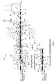
- FIG. 1 is a schematic side view showing a production line 20 of an absorbent article 1.
- a defective-workpiece discharging device that discharges a workpiece having a defect to a discharge path from a conveyance path that conveys a plurality of workpieces relating to absorbent articles in a conveyance direction at a predetermined conveyance pitch, including:
- the controller discharges to the discharge path at least one adjacent workpiece positioned on an upstream side of the specific workpiece and at least one adjacent workpiece positioned on a downstream side, in addition to the specific workpiece.
- the workpieces positioned adjacent to the defective workpiece on the upstream side and on the downstream side are caught up and discharged. Therefore, discharge failure of the defective workpieces can be reliably prevented.
- the controller discharges to the discharge path N (N being an integer of two or more) adjacent workpieces positioned on the downstream side of the specific workpiece, in addition to the specific workpiece, and the end of the first conveyance path on the sorting mechanism side and the predetermined position separated by a distance greater than or equal to N times the conveyance pitch.
- N being an integer of two or more
- the passage detection sensor detects the passage of a workpiece at the predetermined position, the predetermined position is located from the abovementioned end of the first conveyance path at a distance greater than or equal to N times the conveyance pitch.
- N adjacent workpieces on the downstream side will still be on the first conveyance path. Therefore, these N workpieces are passing the abovementioned end or the upstream side of the end, and are caught up and discharged to the discharge path.
- N is an integer of two or more. Therefore, a defective workpiece is caught up and discharged via the discharge path together with several workpieces. This can further increase the discharge accuracy of defective workpieces.
- a dividing mechanism that generates the workpieces by dividing a continuous sheet-like member at a predetermined pitch in the conveyance direction is disposed upstream from the first conveyance path, the continuous sheet-like member being continuous in the conveyance direction, processing for providing a space between adjacent workpieces in the conveyance direction is performed between the dividing mechanism and the first conveyance path, such that the workpieces are conveyed at the conveyance pitch on the first conveyance path, the defect detection sensor detects the defect in the continuous sheet-like member and outputs the defect detection signal, and in a case where it is determined based on the defect detection signal that the defect in the continuous sheet-like member is placed on both of portions equivalent to two workpieces, the controller increases the number of workpieces that are to be discharged to the discharge path, to larger than a case where it is determined that the defect is located within a portion equivalent to a single workpiece.
- the controller determines that a specific workpiece has a defect, the controller discharges the specific workpiece to the discharge path. According to such a defective-workpiece discharging device, only workpieces that do not have any defects can be sent to the second conveyance path.
- a dividing mechanism that generates the workpieces by dividing a continuous sheet-like member at a predetermined pitch in the conveyance direction is disposed upstream from the first conveyance path, the continuous sheet-like member being continuous in the conveyance direction, processing for providing a space between adjacent workpieces in the conveyance direction is performed between the dividing mechanism and the first conveyance path, such that the workpieces are conveyed at the conveyance pitch on the first conveyance path, the defect detection sensor detects that the defect in the continuous sheet-like member passes a predetermined detection position and outputs the defect detection signal, the controller specify an arrival time when the workpiece having the defect arrives at the predetermined position, by comparing an estimated number of workpieces with a count value, the workpieces being workpieces to be included on a conveyance path from the detection position of the defect detection sensor to the predetermined position of the passage detection sensor, the count value being a number of workpieces that passes the predetermined position of the passage detection sensor, the
- the defective-workpiece discharging device further includes a sensor that outputs a signal indicating a conveyance amount of the workpiece on the first conveyance path, and when a value indicated by the signal that is set to zero at the arrival time and is measured reaches a predetermined threshold, the controller actuates the sorting mechanism and guides the workpiece to the discharge path. According to such a defective-workpiece discharging device, a workpiece having a defect can be more reliably guided to the discharge path.
- the arrival time when the defective workpiece arrives at the passage detection sensor can be specified more precisely.
- FIG. 1 is a schematic side view showing a production line 20 of an absorbent article 1.
- a disposable diaper 1 is produced as an example of the absorbent article 1 that absorbs excretory fluid.
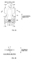
- FIG. 2A is a plan view of an example of this diaper 1
- FIG. 2B is a cross-sectional view of a B-B cross-section in FIG. 2A .
- a configuration in which an absorbent body 3 that is mainly made of pulp fibers is interposed between a liquid permeable top sheet 2 such as a nonwoven fabric and a liquid impermeable back sheet 4 such as a film serves as a main body 11 of the diaper 1.
- the planar shape of the diaper 1 in its opened condition is substantially in hourglass shape.
- a ventral portion 11A and a dorsal portion 11 B which are both end portions of the diaper 1 in the longitudinal direction, are greater in width than a crotch portion 11 C, which is located between the portions 11A and 11 B.
- side flaps 11SF are formed at both end portions of the ventral portion 11A and the dorsal portion 11 B in the width direction.
- a fastening tape member 6 having a pair of hook-and-loop fasteners 5 is adhered to the dorsal portion 11 B.
- the pair of hook-and-loop fasteners 5 open in the width direction of the diaper 1 by means such as separating by perforations 6m in a middle portion of the member 6 in the width direction. Therefore, the fastening tape member 6 has a function to fasten the dorsal portion 11 B to the ventral portion 11A when the diaper 1 is worn.
- elastic members such as a rubber thread (not shown) may be disposed in the longitudinal direction at portions on both sides of the diaper 1 in the width direction.
- stand-up gathers (not shown) may be disposed at the portions on the both sides in the width direction.
- the production line 20 of the diaper 1 has a plurality of conveyance mechanisms 22, 22, ... for conveying semi-finished products 1a, 1b and so on of the diaper 1 in the conveyance direction.
- suction conveyor belts 22 having a suctioning function on the surface of an endless belt are used, the surface of an endless belt serving as a placement surface.
- the endless belts of the suction conveyor belts 22 are driven circumferentially with a drive source such as a motor (not shown). In some cases, conveyance rollers may also be used. While the semi-finished products 1 a, 1b, ... are being conveyed by the conveyance mechanisms 22 in the conveyance direction, the semi-finished product 1a, 1b, ... are sequentially subjected to various processes such as bonding of other components, folding, cutting and the like; thereby the diapers 1 are completely formed.
- the direction perpendicular to the conveyance direction of the diaper 1 (a direction perpendicular to the paper surface in FIG. 1 ) is also referred to as the "CD direction”.
- the downstream side and the upstream side in the conveyance direction may be also respectively referred to as forward and backward.
- the production line 20 has a plurality of reels 25 and 25.
- the reels 25 are respectively installed with respect to a top sheet 2 and a back sheet 4, for example.
- the sheets 2 and 4 are both fed into the production line 20 in the form of sheet rolls formed by spooling the sheets.
- Sheet rolls 2r and 4r are respectively attached to the corresponding reels 25 and unwound in the form of a continuous sheet.
- the production line 20 has main processing devices such as a fiber depositing device 30, a rotary die cutter device 40, a rotary cutter device 50 and the like.
- the production line 20 On the downstream side in the conveyance direction, the production line 20 has a defective-item discharging device 60 that discharges defective diapers 1 from the production line 20.
- the fiber depositing device 30 forms the absorbent bodies 3 by shaping pulp fibers, which is the main raw material of the absorbent bodies 3, into a predetermined shape such as an approximate rectangular parallelepiped. Then, the fiber depositing device 30 places the formed absorbent bodies 3 on a suction conveyor belt 22 at a product pitch P1 in the conveyance direction.
- a merging position G4 with the back sheet 4 is located. That is, at the position G4, the back sheet 4 is supplied from below in the form of a continuous sheet. On the upper surface of the back sheet 4, the absorbent bodies 3 are placed at the product pitch P1.
- a merging position G2 of the top sheet 2 is located near the merging position G4. Therefore, at the position G2, the top sheet 2 is supplied to the semi-finished product 1 a from above in the form of a continuous sheet, the semi-finished product 1a having the back sheet 4 and the absorbent bodies 3 which are placed on back sheet 4. The sheet 2 is attached to the back sheet 4 so as to cover the absorbent bodies 3 from above. Thereby, the semi-finished product 1a becomes the semi-finished product 1b.
- a delivery device attaches a single sheet of fastening tape member 6 (not shown) are attached to the top sheet 2 of the semi-finished product 1b at the product pitch P1. Thereby, the semi-finished product 1 b becomes the semi-finished product 1 c.
- the rotary die cutter device 40 is arranged.
- This device 40 has a cutter roll 41 and an anvil roll 42 that are driven and rotate opposite to each other. Then, when the semi-finished product 1 c passes the nip between these rolls 41 and 42, these rolls 41 and 42 cut out both end edges of the semi-finished product 1c in the CD direction in an approximately semicircular shape at the product pitch P1. As a result, the semi-finished product 1 c is formed into the semi-finished product 1d having the aforementioned approximately hourglass shape.
- the semi-finished product 1d is then passed through to a folding mechanism (not shown).
- the side flaps 11SF and 11SF are each folded inwardly in the CD direction, the side flaps 11SF and 11SF being formed on either side in the CD direction in the aforementioned approximately semicircular cutting out process.
- the semi-finished product 1d becomes the semi-finished product 1e.
- the semi-finished product 1 e is sent to the next rotary cutter device 50.
- the rotary cutter device 50 also has a cutter roll 51 and an anvil roll 52 that are driven and rotate opposite to each other. Then, when the semi-finished product 1e passes the nip between these rolls 51 and 52, these rolls 51 and 52 divide the semi-finished product 1e at the product pitch P1. Thereby, diapers 1 separated individually on a product-by-product basis are finished.
- the diapers 1 are then sent to the defective-item discharging device 60 (corresponding to defective-workpiece discharging device).
- the diapers 1 are sorted into conforming items and defective items while being conveyed.
- the conforming items are sent directly to the downstream process through the conveyance path 81t (see lower part of FIG. 1 ).
- the defective items are discharged from the production line 20 via the discharge path 100t (see upper part of FIG. 1 ). Note that this judgment is performed by the controller 110 based on the signals from various sensors 92, 94, 96, 97 and 98 arranged at appropriate positions on the conveyance path of the production line 20. This will be described later.
- the above-mentioned production line 20 operates under the premise of continuous production. Therefore, essentially materials required in production are supplied continuously so as to not run out.
- a pair of reels 25 and 25 is provided for each of the sheet rolls 2r and 4r of the top sheet 2 and the back sheet 4.
- the other reel 25 is in standby.
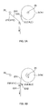
- a leading end 2LE (4LE) of the standby sheet roll 2r (4r) is joined to a tail end 2TE (4TE) of the sheet 2 (4) that is being fed, as shown in FIG. 3B .
- the sheets are connected by adhesive tape, hot melt adhesive, heat sealing, or the like, for example. Continuous supply of material is thereby carried out.
- a joint portion 2j (4j) serving as the connecting portion between the above-mentioned leading end 2LE (4LE) and tail end 2TE (4TE) is naturally an irregular portion.
- a diaper 1 (hereinafter, also referred to as product 1) that includes this portion 2j (4j) will be a defective item.
- a product 1 when attaching a component such as the fastening tape member 6 to the semi-finished product 1b, if the attaching position is outside an allowable range, a product 1 will also be a defective item. Therefore, this defective item will be discharged out of the production line 20 by the defective-item discharging device 60.
- the sensors 92, 94 and 96 for detecting defects such as the above-mentioned joint portion 2j (4j) and specifying defective items from among a plurality of individual diapers 1 are provided for each type of defect. And, defect detection signals from the sensors 92, 94 and 96 are transmitted to the after-mentioned controller 110, which results in discharging defective items.
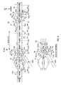
- FIG. 4 is a schematic side view of the defective-item discharging device 60.
- the defective-item discharging device 60 is disposed downstream from the rotary cutter device 50 closely; the rotary cutter device 50 (corresponding to dividing mechanism) divides the semi-finished product 1e in product units and generates the diapers 1.
- the divided diapers 1 are continuously sent directly to the conveyance path 61t of the defective-item discharging device 60 by the rotation of the rolls 51 and 52 of the rotary cutter device 50.
- This defective-item discharging device 60 includes: a first conveyor 61 that is disposed downstream from the rotary cutter device 50 and forms the first conveyance path 61t; a second conveyor 81 that is disposed downstream from this first conveyor 61 and forms the second conveyance path 81t; a sorting conveyor 71 (corresponding to sorting mechanism) that is arranged between these first and second conveyors 61 and 81 and whose conveyance path 71t alternatively connects to either the second conveyance path 81t or the discharge path 100t by a swinging movement; a group of sensors ( FIG. 1 ) consisting of the sensors 92, 94, 96 and 97 for detecting defective items and the sensor 98 for detecting the state of the first conveyor 61; and the controller 110 ( FIG. 1 ) that controls the sorting conveyor 71 based on the various signals output from the group of sensors.
- the first conveyor 61 has a pair of upper and lower endless belts 62u and 62d.
- the lower endless belt 62d is wrapped around a pair of front and back rollers 63d and 63d in the conveyance direction. At least one of these rollers 63d and 63d is driven and rotate by driving power from a motor (not shown) which serves as a drive source; thereby, the lower endless belt 62d moves circumferentially.
- the lower endless belt 62d has a plurality of air intake holes (not shown) in the surface, and thereby sucks and holds the diapers 1 placed on the surface.
- the upper endless belt 62u is wrapped around a pair of front and back rollers 63u and 63u in the conveyance direction.
- the upper endless belt 62u is pressed towards the lower endless belt 62d by a predetermined pressing force so that the diapers 1 are conveyed being sandwiched between the upper endless belt 62u and the lower endless belt 62d.
- the diapers 1 thereby move along the first conveyance path 61t formed between the upper endless belt 62u and the lower endless belt 62d together with these endless belts 62u and 62d.
- the diapers 1 are passed to the sorting conveyor 71 at the downstream end portion 61 e of the first conveyance path 61 t.
- the upper endless belt 62u may be constituted as a follower belt that is circumferentially driven by a driving force obtained from the lower endless belt 62d.
- the upper endless belt 62u may be constituted as a drive belt that is circumferentially driven by a driving force transmitted from the above-mentioned motor by an appropriate gear transmission mechanism or the like. In the circumferential driving of the drive belt, it goes without saying that the upper endless belt 62u is circumferentially driven in synchronization with the lower endless belt 62d.
- the conveyance velocity V61 of this first conveyor 61 is also maintained on the sorting conveyor 71 and the second conveyor 81. Therefore, the expanded conveyance pitch P2 is at least maintained in a range from the first conveyor 61 to the second conveyor 81.
- this expanded conveyance pitch P2 is set to a length greater than or equal to a full length L71t of the conveyance path 71t of the sorting conveyor 71. Therefore, when discharging a targeted diaper 1 by the swinging movement of the sorting conveyor 71, only the targeted diaper 1 can be selectively guided to the discharge path 100t without affecting the diaper 1 adjacent before or after the targeted diaper 1.
- the second conveyor 81 also has a pair of upper and lower endless belts 82u and 82d.
- the lower endless belt 82d is wrapped around a pair of front and back rollers 83d and 83d in the conveyance direction. At least one of these rollers 83d and 83d is driven and rotate by driving power from a motor (not shown) which serves as a drive source; thereby, the lower endless belt 82d moves circumferentially.
- the lower endless belt 82d has a plurality of air intake holes (not shown) in the surface, and thereby sucks and holds the diapers 1 placed on the surface.
- the upper endless belt 82u is wrapped around a pair of front and back rollers 83u and 83u in the conveyance direction.
- the upper endless belt 82u is pressed towards the lower endless belt 82d by a predetermined pressing force so that the diapers 1 are conveyed being sandwiched between the upper endless belt 82u and the lower endless belt 82d.
- the diapers 1 thereby move along the second conveyance path 81t formed between the upper endless belt 82u and the lower endless belt 82d together with these endless belts 82u and 82d.
- Conforming diapers 1 are passed to an appropriate conveyor 150 of the downstream process at the downstream end portion 81e of the second conveyance path 81t.
- the upper endless belt 82u may be either a follower belt or a drive belt.
- the sorting conveyor 71 also has a pair of upper and lower endless belts 72u and 72d.
- the lower endless belt 72d is wrapped around a pair of front and back rollers 73d and 73d in the conveyance direction. At least one of these rollers 73d and 73d is driven and rotate by driving power from a motor (not shown) which serves as a drive source; thereby, the lower endless belt 72d moves circumferentially.
- the lower endless belt 72d has a plurality of air intake holes (not shown) in the surface, and thereby sucks and holds the diapers 1 placed on the surface.
- the upper endless belt 72u is wrapped around a pair of front and back rollers 73u and 73u in the conveyance direction.
- the upper endless belt 72u is pressed towards the lower endless belt 72d by a predetermined pressing force so that the diapers 1 are conveyed being sandwiched between the upper endless belt 72u and the lower endless belt 72d.
- the diapers 1 thereby move along the conveyance path 71t formed between the upper endless belt 72u and the lower endless belt 72d together with these endless belts 72u and 72d.
- the diapers 1 are passed to the second conveyor 81 or the discharge path 100t at the downstream end 71 e of the conveyance path 71 t.
- the upper endless belt 72u may be either a follower belt or a drive belt.
- the upper endless belt 72u and the lower endless belt 72d relating to the sorting conveyor 71 are respectively configured so that the rollers 73u and 73d serving as end portions on the downstream side are swingable up and down on rotation axes C73u and C73d of the upstream rollers 73u and 73d.
- hydraulic cylinders 75 that extend and retract pistons are respectively provided for the upper endless belt 72u and the lower endless belt 72d as a drive mechanism of this swinging movement.
- electromagnetic valves or the like serving as movement controllers 75s for switching the extension/retraction movement of the hydraulic cylinders 75 are provided.
- the conveyance path 71t of the sorting conveyor 71 is configured so that an end 71e2 of the conveyance path 71t on the second conveyor 81 side can be swung up and down on the fulcrum of an end 71 e1 on the first conveyor 61 side, by the extension/retraction movement of these hydraulic cylinders 75. Therefore, targeted diapers 1 can be discharged to the discharge path 100t by selectively connecting either the conveyance path 71t to the second conveyance path 81 t of the second conveyor 81 or the discharge path 100t positioned therebelow.
- the group of sensors includes: the defect detection sensors 92, 94 and 96 that detects defects; the passage detection sensor 97 that is provided on the first conveyor 61 and detects passage of the diapers 1; and the state monitoring sensor 98 that monitors the conveyance state of the first conveyor 61.
- the defect detection sensors 92, 94 and 96 are provided for each type of possible defects.
- the following things are expected as defects: the joint portions 2j of the top sheet 2; the joint portions 4j of the back sheet 4; the fastening tape members 6 attached outside the allowable range; and the like.
- the joint portion detection sensor 92 for the top sheet 2 is disposed between the feeding position of the reel 25 and the aforementioned merging position G2, for example, and the joint portion detection sensor 94 for the back sheet 4 is disposed between the feeding position of the reel 25 and the aforementioned merging position G4, for example.
- These sensors 92 and 94 detect the joint portions 2j and 4j and output a defect detection signal to the controller 110 whenever the joint portions 2j and 4j pass predetermined detection positions 92p and 94p.
- phototubes or the like that output a signal of a magnitude that depends on the amount of received light are given as an example of these sensors 92 and 94.
- the sensor 96 that detects attachment position defects of the fastening tape member 6 is installed immediately downstream from the delivery position of the fastening tape member 6 to the semi-finished product 1d.
- This sensor 96 is an infrared camera, for example.
- the camera operates based on a synchronization signal from a rotary encoder 54 of the rotary cutter device 50, for example. Thereby the camera captures an image of the semi-finished product 1e every time when products 1e are conveyed by the product pitch P1 and acquires a temperature distribution image corresponding to a single product 1.
- the images undergo a treatment such as binarization.
- an actual attachment position is specified with an outline position reference of each product 1 (accurately, each potential product 1), and it is determined whether the specified attachment position falls within an allowable range of prescribed attachment target positions decided from the outline position. If the specified attachment position does not fall within the allowable range, the defect detection signal is output to the controller 110.
- the configuration for performing binarization and the above-mentioned determination may be provided on the controller 110 side.
- the passage detection sensor 97 is disposed on the first conveyor 61.
- the detection position 97p for detecting the passage of the diapers 1 is also set on the first conveyance path 61t. Therefore, whenever the downstream end of a diaper 1 passes the detection position 97p, the passage detection sensor 97 outputs a passage detection signal to the controller 110. This will be described later.
- the state monitoring sensor 98 is a rotary encoder 98 provided in a roller 63d of the first conveyor 61, for example ( FIG. 1 ).
- This encoder 98 measures the rotation angle (amount of rotation) of the roller 63d of the first conveyor 61. And, the encoder 98 outputs a digital value signal whose value is proportional to the rotation angle or a pulse signal whose number of pulses is proportional to the rotation angle to the controller 110.
- the controller 110 is an appropriate computer such as a PLC (programmable logic controller) and controls the swinging movement of the sorting conveyor 71 based on the signals output from the sensors 92, 94, 96, 97, 98 and the like. In other words, the controller 110 controls the hydraulic cylinders 75 serving as the drive mechanism of the sorting conveyor 71.
- PLC programmable logic controller
- the estimated number of potential diapers 1 to be products which are included on the conveyance path from the detection position 92p of the joint portion detection sensor 92 to the detection position 97p of the passage detection sensor 97 on the first conveyor 61 in FIG. 1 is a known value based on the design, the actual facility layout or the like. Counting the number of the diapers 1 that pass the detection position 97p of the passage detection sensor 97 starts at the time when the joint portion detection sensor 92 detects the joint portion 2j; the number of the diapers 1 is counted based on the passage detection signal of the passage detection sensor 97 of the first conveyance path 61t.
- the defective item 1 can be discharged by swinging the sorting conveyor 71 downward and connecting to the discharge path 100t when the defective item 1 is conveyed by a predetermined conveyance amount from the arrival time (starting point). Therefore, based on this discharge processing logic, positioning the detection position 97p of the passage detection sensor 97 as close as possible to the sorting conveyor 71 is considered desirable in terms of discharge accuracy.
- the detection position 97p at which the passage detection sensor 97 detects the passage of diapers 1 is set to a position upstream from a downstream end 61ted of the first conveyance path 61t (corresponding to the end on the sorting mechanism side) at a distance greater than or equal to the length of the conveyance pitch P2.
- the downstream end of the defective item 1 passes the detection position 97p, the adjacent diaper 1 on the downstream side should also still be on the first conveyance path 61t. Therefore, the defective item 1 can be caught up and discharged to the discharge path 100t together with at least one diaper 1 on the downstream side of the defective item 1.
- the above-mentioned detection position 97p is set to a position at a distance greater than or equal to N times the length of the conveyance pitch P2 from the downstream end 61ted of the first conveyance path 61t.
- N diapers 1 positioned downstream from a defective item 1 can be reliably caught up and discharged. This can increase the discharge accuracy of defective items 1 further. Also, if N diapers 1 located upstream from the defective item 1 are caught up and discharged, the possibility of discharge failure will be further reduced.
- the number of diapers 1 to be caught up on either side of a defective item 1 is set to N. That is, the number of the diapers 1 located upstream from a defective item 1 to be caught up and discharged together is set to N, and the number of the diapers 1 on the downstream side to be caught up and discharged together is similarly set to N.
- the detection position 97p of the passage detection sensor 97 is set to a position from the downstream end 61ted of the first conveyance path 61t at a distance L satisfying the following equation 1. L ⁇ N ⁇ P ⁇ 2
- FIG. 6 is a flow diagram of discharge processing executed by a discharge processing unit of the controller 110.
- the discharge processing unit is constituted by a program, for example.
- the discharge processing is performed by a processor of the controller 110 reading out a discharge processing program from a memory or the like and executing the read program. Therefore, although the discharge processing unit is described as performing the discharge processing in the following description, the processing is actually performed by the processor.
- the detection sensor 92 for the top sheet in FIG. 1 detects the passage of the joint portion 2j of the top sheet 2, the detection sensor 92 outputs a defect detection signal to the discharge processing unit of the controller 110 (S10).
- the discharge processing unit having received this signal, operates a counter included in the discharge processing unit. That is, the count value of the counter is set to zero at the time when the defect detection signal is received, and thereafter "1" adds to the count value every time when a passage detection signal is received from the passage detection sensor 97 of the first conveyance path 61t (S20).
- the discharge processing unit sequentially compares the count value and a predetermined threshold Kth (S30). Note that this threshold Kth is the aforementioned estimated number of diapers 1, and is stored in advance in a memory of the controller 110.
- this threshold Kth indicates the number of diapers 1 that exist on the conveyance path between the detection position 92p of the joint portion detection sensor 92 and the detection position 97p of the passage detection sensor 97 (accurately, number of items to be a diaper 1).
- the threshold Kth is represented by the following equation 2, for example.
- Kth D ⁇ 1 / P ⁇ 1 + D ⁇ 2 / P ⁇ 2
- D1 in the above equation 2 is a path length of the conveyance path from the detection position 92p of the joint portion detection sensor 92 to a device center of the rotary cutter device 50.
- D2 is a path length of the conveyance path from the device center of the rotary cutter device 50 to the detection position 97p of the passage detection sensor 97.
- the reason for dividing the path length from the detection position 92p to the detection position 97p into the two path lengths D1 and D2 on the right side of the above equation 2 is that the conveyance pitch per diaper changes at the rotary cutter device 50, from the product pitch P1 to the conveyance pitch P2 (>P1) (see FIG. 4 ).
- the detection positions 92p and 97p of the sensors 92 and 97 are adjusted so that the value of D1/P1 and the value D2/P2 in the equation 2 are within a range of ⁇ 5% of an integer value. It is more desirable that the detection positions 92p and 97p are adjusted so that the values are equal to the integer value. This makes it possible to more accurately specify the arrival time of a defective item 1 when a defective item 1 arrives at the detection position 97p of the passage detection sensor 97.
- the discharge processing unit determines that the leading edge (downstream end) of the diaper 1 having the joint portion 2j has arrived at the detection position 97p of the passage detection sensor 97 at the time when the threshold is exceeded.
- conveyance amount of the first conveyor 61 is set to zero. Thereafter, the discharge processing unit measures the conveyance amount based on the signal of the encoder 98 of the first conveyor 61 (S40). The discharge processing unit sequentially compares the value of this conveyance amount and a predetermined threshold Tth (S50).
- this threshold Tth is also stored in advance in the memory of the controller 110.
- This threshold Tth indicates the distance between a position of N th diaper 1 downstream from this defective item 1 and the downstream end 61ted of the first conveyance path 61 at the time when a defective item 1 which is a diaper 1 having the joint portion 2j passes (arrives at) the detection position 97p of the passage detection sensor 97.
- the threshold Tth is represented with the following equation 3 using the values L, N and P2 mentioned above.
- the discharge processing unit determines that N th diaper 1 positioned downstream to be discharged together with the defective item 1 has arrived at the downstream end 61ted of the first conveyance path 61t.
- the discharge processing unit transmits a discharge signal to the movement controllers 75s such as electromagnetic valves of the sorting conveyor 71.
- the movement controllers 75s control the hydraulic cylinders 75 and 75 to switch the connection point of the conveyance path 71t of the sorting conveyor 71 from the second conveyance path 81t to the discharge path 100t (S60).
- this discharge signal is continuously transmitted (output) until Nth diaper 1 positioned upstream from the defective item 1 is discharged from the discharge path 100t.
- the movement controllers 75s maintain the state in which the conveyance path 71t of the sorting conveyor 71 is connected to the discharge path 100t.
- the defective item 1 which is a diaper 1 having the joint portion 2j, N diapers 1 before the defective item 1 and N diapers 1 after the defective item 1 are discharged via the discharge path 100t.
- the discharge processing unit stops transmission of the discharge signal, based on the aforementioned counter value, for example. That is, when the counter value exceeds a second threshold Kth2 of the following equation 4, the discharge processing unit stops transmission of the discharge signal (S70, S80).
- Kth ⁇ 2 Kth ⁇ 1 + L ⁇ 71 ⁇ t + L / P ⁇ 2 + N Therefore, when N diapers 1 positioned upstream from the defective item 1 have finished being discharged, the connection point of the sorting conveyor 71 is again returned to the second conveyance path 81t. Thereafter, diapers 1 which are conveyed are sent as conforming items to the downstream process of the production line 20 through the second conveyance path 81t.
- the second threshold Kth2 is also stored in advance in the memory of the controller 110.
- the controller 110 has a plurality of discharge processing programs which serving as a discharge processing unit, the programs corresponding to the sensors 92, 94 and 96 respectively.
- the processor of the controller 110 executes the discharge processing programs in parallel. A discharge signal will thereby be transmitted (output) to the movement controllers 75s of the sorting conveyor 71 from each discharge processing unit.
- the movement controllers 75s of the sorting conveyor 71 control the hydraulic cylinders 75 of the sorting conveyor 71 so as to connect the conveyance path 71t to the discharge path 100t.
- the movement controllers 75s control the hydraulic cylinders 75 so as to connect the conveyance path 71t to the second conveyance path 81 t. Therefore, even when defective diapers 1 whose defect is different from each other are being conveyed located closely to each other, the sorting operation can be performed smoothly. In addition thereto, only diapers 1 without any defects can be sent to a downstream process via the second conveyance path 81t.
- a sensor having the following function is used for a sensor such as the joint portion detection sensor 92 for the top sheet and the joint portion detection sensor 94 for back sheet. That is, it is a sensor that can detect whether a joint portion 2j (4j) is placed on both of adjacent diapers 1 and 1 (accurately, portions equivalent to diapers 1 and 1) on the top sheet 2 (the back sheet 4) which is a continuous sheet-like member.
- the discharge processing unit determines, based on the defect detection signal transmitted from the sensor 92 (94), that "the joint portion 2j (4j) is located within only a single diaper 1 (accurately, potential diaper 1), not on any of the adjacent diapers", the discharge processing unit performs the same discharge processing as mentioned above.
- the discharge processing unit decides the timing for starting transmission of a discharge signal to the movement controllers 75s, based on the downstream one of the adjacent diapers 1 and 1. Also, the discharge processing unit decides the timing for stopping transmission of the discharge signal, based on the upstream one of the adjacent diapers 1 and 1.
- the transmission start timing will be the same as when the joint portion 2j (4j) is placed on only either of the adjacent diapers 1 and 1.
- the transmission stop timing will be late by a time period corresponding to one diaper, compared to the case where the joint portion 2j (4j) is placed on only either of the adjacent diapers 1 and 1.
- the aforementioned infrared camera is given as an example of such a sensor capable of detecting whether the joint portion 2j (4j) is placed on both of the adjacent diapers 1 and 1.
- this camera operates based on the synchronization signal from the encoder 54 of the rotary cutter device 50.
- the camera captures an image of the top sheet 2 and the back sheet 4 every time when the sheets are conveyed by the product pitch P1 and acquires a temperature distribution image corresponding to a single product 1.
- the acquired image is immediately transmitted to the discharge processing unit every time the image is captured. Then, the discharge processing unit performs a processing such as binarization on the images.
- the position of the joint portion 2j (4j) is specified with an outline position reference of each product 1 (accurately, each potential product 1), and it is determined whether the position of the specified joint portion 2j (4j) is placed on the outline position. If the specified joint portion 2j (4j) is placed on the outline position, the discharge processing unit determines that "the joint portion 2j (4j) is placed on both of the adjacent diapers 1 and 1". If the specified joint portion 2j (4j) is not placed on the outline position, the discharge processing unit determines that "the joint portion 2j (4j) is placed on only either of the adjacent diapers 1 and 1".
- the defective-item discharging device 60 a device in which a part of conveyor such as the conveyor 71 performs a swinging movement is illustrated as the defective-item discharging device 60.
- the present invention is not limited thereto.
- the defective-item discharging device 60a may be constituted as shown in FIG. 7A . That is, with regard to the downstream end portion 61e of the first conveyor 61 which forms the first conveyance path 61t, the first conveyor 61 is constituted such that only the lower endless belt 62d is positioned so as to project on the downstream side.
- the second conveyor 81 is constituted such that only the lower endless belt 82d is positioned so as to project on the upstream side. Also, an interval ⁇ is provided between these end portions 61 e and 81e. Above the interval ⁇ , an endless belt 72a which is a part of the sorting mechanism 71a is disposed so as to extend over the interval ⁇ .
- This endless belt 72a is constituted as a suction conveyor belt, and thereby sucks and receives diapers 1 that have passed the first conveyance path 61t, onto the surface of the endless belt 72a. These diapers 1 are conveyed in hanging state by the suction and delivered to the second conveyance path 81t.
- this endless belt 72a is provided with a detaching-and-dropping mechanism 77 for detaching and dropping the diaper 1 conveyed in the hanging state from the surface of the endless belt 72a.
- a detaching-and-dropping mechanism 77 for detaching and dropping the diaper 1 conveyed in the hanging state from the surface of the endless belt 72a.
- an air blow mechanism 77a ( FIG. 7A ) which can inject or cease to inject air downward by controlling an appropriate air source; a pusher mechanism 77c ( FIG. 7B ) which can cause a rod-like member 77b to emerge downwardly by controlling an appropriate actuator such as a hydraulic cylinder; and the like.
- the concept of the present invention is also applicable to a defective-item discharging device 60a having this configuration. That is, the detection position 97p of the passage detection sensor 97 is set to a position at a distance greater than or equal to the conveyance pitch P from downstream end 61 ted of the first conveyance path 61t in FIGS. 7A and 7B . In this way, the diaper 1 immediately before the defective diaper 1 can also be caught up and discharged.
- the threshold Kth and the second threshold Kth2 are calculated in advance based on the equations 2 and 4, and are stored in the memory of the controller 110.
- these thresholds Kth and Kth2 may be obtained by performing the arithmetic operations of the equations 2 and 4 every time when the discharge processing unit of the controller 110 executes the discharge processing shown in FIG. 6 .
- the threshold Tth is calculated in advance based on the equation 3, and is stored in the memory of the controller 110.
- the invention is not limited thereto.
- the threshold Tth may be obtained by performing the arithmetic operation of the equation 3 may be calculated every time when the discharge processing unit of the controller 110 executes the discharge processing in FIG. 6 .
- the threshold Tth relating to step S50 of the discharge processing in FIG. 6 is defined by distance, and comparison of this threshold Tth and the conveyance amount of the first conveyor 61 is performed at step S50.
- the invention is not limited thereto.
- the following configuration may also be employed: a threshold ⁇ th of a rotation angle corresponding to the threshold Tth is obtained by dividing the value of the threshold Tth by the value obtained by multiplying the diameter of the roller 63d of the first conveyor 61 by the ratio of the circumference; at step S50 of the discharge processing, comparison of the threshold ⁇ th and a rotation angle ⁇ output by the encoder 98 of the first conveyor 61 is be performed; and the output timing (transmission start timing) of the discharge signal is controlled.
- the joint portion 2j of the top sheet 2, the joint portion 4j of the back sheet 4, and the like were illustrated as types of the defect.
- the present invention is not limited thereto.
- a sensor for detecting the displacement of the absorbent body 3 may be provided so as to transmit a detection signal to the controller 110 when the displacement from the allowable range is detected.
- the aforementioned infrared camera or the like can be used for the sensor.
- the threshold Tth relating to step S50 of the discharge processing in FIG. 6 is defined by distance, and comparison of this threshold Tth and the conveyance amount of the first conveyor 61 is performed at step S50.
- the invention is not limited thereto.
- the threshold Tth may be defined by time.
- the threshold Tth is calculated, for example, by dividing the distance L by the value of the conveyance velocity V61 of the first conveyor 61 at the time (arrival time) when a defective item 1 arrives at the detection position 97p of the passage detection sensor 97.
- a timer of the discharge processing unit is set to the starting point at the arrival time, and then the timer starts a count.
- the discharge processing unit transmits a discharge signal to the movement controllers 75s of the sorting conveyor 71.
- the diaper 1 is illustrated as a workpiece.
- the invention is not limited thereto.
- a semi-finished product prior to becoming the diaper 1 is acceptable, as long as it is divided individually.
- the operating time required for the swinging movement of the sorting conveyor 71 is not described (i.e., a time period required to connect to the discharge path 110t the conveyance path 71t which is connected to the second conveyance path 81t; and a time period required to connect to the second conveyance path 81t the conveyance path 71t which is connected to the discharge path 100t). It is desirable that this operating time is appropriately set to a time period that is shorter than or equal to a time period during which the downstream end of a diaper 1 to be discharged moves from the downstream end 61ted of the first conveyance path 61t to the downstream end 71e of the conveyance path 71t of the conveyor 71. This operating time is set more desirably to a time period shorter than this time period.
Landscapes
- Engineering & Computer Science (AREA)
- Mechanical Engineering (AREA)
- Absorbent Articles And Supports Therefor (AREA)
- Controlling Sheets Or Webs (AREA)
- Separation, Sorting, Adjustment, Or Bending Of Sheets To Be Conveyed (AREA)
- Sorting Of Articles (AREA)
Abstract
Description
- The present invention relates to a defective-workpiece discharging device used when producing absorbent articles such as disposable diapers.
- Conventionally, with a production line for products in general, not only absorbent articles such as disposable diapers, discharge of defective items from a conveyance path is carried out while finished products are being conveyed on the conveyance path at a predetermined conveyance pitch ([PTL 1]).
- [PTL 1]:
JP 2001-89003A - As a device for the foregoing purpose, the following configuration can be considered (see
FIG. 5 ). As conveyance paths for conveyingproducts 1 at a conveyance pitch P2, afirst conveyance path 61t and asecond conveyance path 81t downstream therefrom are included. Asorting mechanism 71 is disposed between thefirst conveyance path 61t and thesecond conveyance path 81t. In the case where aproduct 1 that has passed thefirst conveyance path 61t is a conforming item, thesorting mechanism 71 sorts theproduct 1 to thesecond conveyance path 81t, whereas in the case where theproduct 1 is a defective item, thesorting mechanism 71 sorts theproduct 1 to adischarge path 100t. - This sorting operation is performed using, for example, a
passage detection sensor 97 that detects the passage of theproducts 1 on thefirst conveyance path 61t. That is, when thepassage detection sensor 97 detects that adefective item 1 has passed apredetermined position 97p on thefirst conveyance path 61t, a passage detection signal is output from thesensor 97, and acontroller 110, having received the passage detection signal, control thesorting mechanism 71 to discharge thedefective item 1 to thedischarge path 100t. - It can be considered to additionally discharge the conforming
item 1 which is positioned immediately before thedefective item 1, in consideration of the possibility of failing to discharge thedefective item 1.
However, in this case, depending on the settings of the conveyance pitch P2 and the settings of thepredetermined position 97p which is the passage detection position of thepassage detection sensor 97, the sorting operation is not always perfomed in a timely manner. In other words, when an attempt is made to sort the conformingitem 1 that is located immediately before thedefective item 1 and that should be discharged to thedischarge path 100t, the conformingitem 1 could have already passed thesorting mechanism 71 and arrived at thesecond conveyance path 81t. - The invention has been made in view of the above conventional problems, and an advantage thereof is to increase the accuracy with which a workpiece to be discharged from a conveyance path, such as a defective workpiece or a workpiece positioned immediately before the defective workpiece, is discharged.
- In order to achieve the above advantage, a primary aspect of the invention is directed to a defective-workpiece discharging device that discharges a workpiece having a defect to a discharge path from a conveyance path that conveys a plurality of workpieces relating to absorbent articles in a conveyance direction at a predetermined conveyance pitch, including:
- a first conveyance path and a second conveyance path that are included in the conveyance path, the second conveyance path being located downstream from the first conveyance path;
- a sorting mechanism
that is disposed between the first conveyance path and the second conveyance path, and
that sorts the workpieces into either one of the second conveyance path and the discharge path, the workpieces having passed the first conveyance path; - a defect detection sensor that detects the defect and outputs a defect detection signal;
- a passage detection sensor
that is disposed on the first conveyance path, and
that detects passage of the workpieces at a predetermined position on the first conveyance path and outputs a passage detection signal; and - a controller that controls a sorting operation of the sorting mechanism, based on the defect detection signal and the passage detection signal, wherein
- an end of the first conveyance path on the sorting mechanism side and the predetermined position are separated by a distance greater than or equal to the conveyance pitch.
- Further features of the present invention will be apparent from the description of the specification and the accompanying drawings.
- According to the invention, it is possible to increase the discharge accuracy of workpieces to be discharged from a conveyance path, such as a defective workpiece or a workpiece positioned immediately before the defective workpiece.
-
FIG. 1 is a schematic side view showing aproduction line 20 of anabsorbent article 1. -
FIG. 2A is a plan view of an example of adisposable diaper 1, andFIG. 2B is cross-sectional view of a B-B cross-section inFIG. 2A . -
FIG. 3A and FIG. 3B are explanatory diagrams of ajoint portion 2j (4j) of a sheet 2 (4) which is an example of a defect included in adefective diaper 1. -
FIG. 4 is a schematic side view of a defective-item discharging device 60. -
FIG. 5 is an explanatory diagram of a problem in the case where apassage detection sensor 97 is disposed in proximity to asorting conveyor 71. -
FIG. 6 is a flow diagram of discharge processing. -
FIG. 7A and FIG. 7B are schematic side views of a defective-itemdischarging device 60a of other embodiments. - At least the following points will be apparent from the description of the specification and the accompanying drawings.
A defective-workpiece discharging device that discharges a workpiece having a defect to a discharge path from a conveyance path that conveys a plurality of workpieces relating to absorbent articles in a conveyance direction at a predetermined conveyance pitch, including: - a first conveyance path and a second conveyance path that are included in the conveyance path, the second conveyance path being located downstream from the first conveyance path;
- a sorting mechanism
that is disposed between the first conveyance path and the second conveyance path, and
that sorts the workpieces into either one of the second conveyance path and the discharge path, the workpieces having passed the first conveyance path; - a defect detection sensor that detects the defect and outputs a defect detection signal;
- a passage detection sensor
that is disposed on the first conveyance path, and
that detects passage of the workpieces at a predetermined position on the first conveyance path and outputs a passage detection signal; and - a controller that controls a sorting operation of the sorting mechanism, based on the defect detection signal and the passage detection signal, wherein
- an end of the first conveyance path on the sorting mechanism side and the predetermined position are separated by a distance greater than or equal to the conveyance pitch.
- With the above defective-workpiece discharging device, it is desirable that
in a case where it is determined that a specific workpiece among the workpieces has the defect,
the controller discharges to the discharge path at least one adjacent workpiece positioned on an upstream side of the specific workpiece and at least one adjacent workpiece positioned on a downstream side, in addition to the specific workpiece.
According to such a defective-workpiece discharging device, the workpieces positioned adjacent to the defective workpiece on the upstream side and on the downstream side are caught up and discharged. Therefore, discharge failure of the defective workpieces can be reliably prevented. - With the above defective-workpiece discharging device, it is desirable that
in a case where it is determined that a specific workpiece among the workpieces has the defect,
the controller discharges to the discharge path N (N being an integer of two or more) adjacent workpieces positioned on the downstream side of the specific workpiece, in addition to the specific workpiece, and
the end of the first conveyance path on the sorting mechanism side and the predetermined position separated by a distance greater than or equal to N times the conveyance pitch.
According to such a defective-workpiece discharging device, the passage detection sensor detects the passage of a workpiece at the predetermined position, the predetermined position is located from the abovementioned end of the first conveyance path at a distance greater than or equal to N times the conveyance pitch. At the time when the passage detection sensor detects a defective workpiece, N adjacent workpieces on the downstream side will still be on the first conveyance path. Therefore, these N workpieces are passing the abovementioned end or the upstream side of the end, and are caught up and discharged to the discharge path. Here, N is an integer of two or more. Therefore, a defective workpiece is caught up and discharged via the discharge path together with several workpieces. This can further increase the discharge accuracy of defective workpieces. - With the above defective-workpiece discharging device, it is desirable that
a dividing mechanism that generates the workpieces by dividing a continuous sheet-like member at a predetermined pitch in the conveyance direction is disposed upstream from the first conveyance path, the continuous sheet-like member being continuous in the conveyance direction,
processing for providing a space between adjacent workpieces in the conveyance direction is performed between the dividing mechanism and the first conveyance path, such that the workpieces are conveyed at the conveyance pitch on the first conveyance path,
the defect detection sensor detects the defect in the continuous sheet-like member and outputs the defect detection signal, and
in a case where it is determined based on the defect detection signal that the defect in the continuous sheet-like member is placed on both of portions equivalent to two workpieces,
the controller increases the number of workpieces that are to be discharged to the discharge path, to larger than a case where it is determined that the defect is located within a portion equivalent to a single workpiece.
According to such a defective-workpiece discharging device, in the case where a defect is placed on both of two adjacent workpieces in the conveyance direction, the number of workpieces discharged to the discharge path is increased. Therefore, discharge failure of the defective workpieces can be reliably suppressed. - With the above defective-workpiece discharging device, it is desirable that
a plurality of the defect detection sensors are disposed for each type of defects, and
in a case where, based on the defect detection signal of at least one of the plurality of defect detection sensors, the controller determines that a specific workpiece has a defect,
the controller discharges the specific workpiece to the discharge path.
According to such a defective-workpiece discharging device, only workpieces that do not have any defects can be sent to the second conveyance path. - With the above defective-workpiece discharging device, it is desirable that
a dividing mechanism that generates the workpieces by dividing a continuous sheet-like member at a predetermined pitch in the conveyance direction is disposed upstream from the first conveyance path, the continuous sheet-like member being continuous in the conveyance direction,
processing for providing a space between adjacent workpieces in the conveyance direction is performed between the dividing mechanism and the first conveyance path, such that the workpieces are conveyed at the conveyance pitch on the first conveyance path,
the defect detection sensor detects that the defect in the continuous sheet-like member passes a predetermined detection position and outputs the defect detection signal,
the controller specify an arrival time when the workpiece having the defect arrives at the predetermined position, by comparing an estimated number of workpieces with a count value, the workpieces being workpieces to be included on a conveyance path from the detection position of the defect detection sensor to the predetermined position of the passage detection sensor, the count value being a number of workpieces that passes the predetermined position of the passage detection sensor, the count value being set to zero at a time when the defect detection signal is output, the count value being incremented by one every time when a workpiece passes the predetermined position, and
the controller actuates the sorting mechanism based on the arrival time and guides the workpiece to the discharge path.
According to such a defective-workpiece discharging device, a workpiece having a defect can be reliably guided to the discharge path. - With the above defective-workpiece discharging device, it is desirable that
the defective-workpiece discharging device further includes a sensor that outputs a signal indicating a conveyance amount of the workpiece on the first conveyance path, and
when a value indicated by the signal that is set to zero at the arrival time and is measured reaches a predetermined threshold,
the controller actuates the sorting mechanism and guides the workpiece to the discharge path.
According to such a defective-workpiece discharging device, a workpiece having a defect can be more reliably guided to the discharge path. - With the above defective-workpiece discharging device, it is desirable that
the detection position is set to a position at which a value (= D1/P1) is within a range of ±5% of a certain integer value, the value (= D1/P1) being obtained by dividing a path length D1 of a conveyance path from the detection position of the defect detection sensor to the dividing mechanism by the predetermined pitch P1, and
the predetermined position is set to a position at which a value (= D2/P2) is within a range of ±5% of a certain integer value, the a value (= D2/P2) being obtained by dividing a path length D2 of a conveyance path from the dividing mechanism to the predetermined position relating to the passage detection sensor by the conveyance pitch P2.
According to such a defective-workpiece discharging device, the arrival time when the defective workpiece arrives at the passage detection sensor can be specified more precisely. -
FIG. 1 is a schematic side view showing aproduction line 20 of anabsorbent article 1. On thisproduction line 20, adisposable diaper 1 is produced as an example of theabsorbent article 1 that absorbs excretory fluid. -
FIG. 2A is a plan view of an example of thisdiaper 1, andFIG. 2B is a cross-sectional view of a B-B cross-section inFIG. 2A .
A configuration in which anabsorbent body 3 that is mainly made of pulp fibers is interposed between a liquid permeabletop sheet 2 such as a nonwoven fabric and a liquidimpermeable back sheet 4 such as a film serves as amain body 11 of thediaper 1.
The planar shape of thediaper 1 in its opened condition is substantially in hourglass shape. In other words, aventral portion 11A and adorsal portion 11 B, which are both end portions of thediaper 1 in the longitudinal direction, are greater in width than acrotch portion 11 C, which is located between theportions ventral portion 11A and thedorsal portion 11 B in the width direction.
Also, afastening tape member 6 having a pair of hook-and-loop fasteners 5 is adhered to thedorsal portion 11 B. When thediaper 1 is used, the pair of hook-and-loop fasteners 5 open in the width direction of thediaper 1 by means such as separating byperforations 6m in a middle portion of themember 6 in the width direction. Therefore, thefastening tape member 6 has a function to fasten thedorsal portion 11 B to theventral portion 11A when thediaper 1 is worn.
In order to give strechability to portions which formleg openings crotch portion 11C, elastic members such as a rubber thread (not shown) may be disposed in the longitudinal direction at portions on both sides of thediaper 1 in the width direction. Also, stand-up gathers (not shown) may be disposed at the portions on the both sides in the width direction. - As shown in
FIG. 1 , theproduction line 20 of thediaper 1 has a plurality ofconveyance mechanisms semi-finished products 1a, 1b and so on of thediaper 1 in the conveyance direction. For theconveyance mechanisms 22,suction conveyor belts 22 having a suctioning function on the surface of an endless belt are used, the surface of an endless belt serving as a placement surface. The endless belts of thesuction conveyor belts 22 are driven circumferentially with a drive source such as a motor (not shown). In some cases, conveyance rollers may also be used.
While thesemi-finished products 1 a, 1b, ... are being conveyed by theconveyance mechanisms 22 in the conveyance direction, thesemi-finished product 1a, 1b, ... are sequentially subjected to various processes such as bonding of other components, folding, cutting and the like; thereby thediapers 1 are completely formed. - Note that in the following description, the direction perpendicular to the conveyance direction of the diaper 1 (a direction perpendicular to the paper surface in
FIG. 1 ) is also referred to as the "CD direction". Also, the downstream side and the upstream side in the conveyance direction may be also respectively referred to as forward and backward. - As shown in
FIG. 1 , theproduction line 20 has a plurality ofreels reels 25 are respectively installed with respect to atop sheet 2 and aback sheet 4, for example. Thesheets production line 20 in the form of sheet rolls formed by spooling the sheets. Sheet rolls 2r and 4r are respectively attached to the correspondingreels 25 and unwound in the form of a continuous sheet. Theproduction line 20 has main processing devices such as afiber depositing device 30, a rotarydie cutter device 40, arotary cutter device 50 and the like. On the downstream side in the conveyance direction, theproduction line 20 has a defective-item discharging device 60 that dischargesdefective diapers 1 from theproduction line 20. - The
fiber depositing device 30 forms theabsorbent bodies 3 by shaping pulp fibers, which is the main raw material of theabsorbent bodies 3, into a predetermined shape such as an approximate rectangular parallelepiped. Then, thefiber depositing device 30 places the formedabsorbent bodies 3 on asuction conveyor belt 22 at a product pitch P1 in the conveyance direction. - On the downstream side of the placement position, a merging position G4 with the
back sheet 4 is located. That is, at the position G4, theback sheet 4 is supplied from below in the form of a continuous sheet. On the upper surface of theback sheet 4, theabsorbent bodies 3 are placed at the product pitch P1. - Also, a merging position G2 of the
top sheet 2 is located near the merging position G4. Therefore, at the position G2, thetop sheet 2 is supplied to thesemi-finished product 1 a from above in the form of a continuous sheet, thesemi-finished product 1a having theback sheet 4 and theabsorbent bodies 3 which are placed onback sheet 4. Thesheet 2 is attached to theback sheet 4 so as to cover theabsorbent bodies 3 from above. Thereby, thesemi-finished product 1a becomes the semi-finished product 1b. - At a further downstream position, a delivery device (not shown) attaches a single sheet of fastening tape member 6 (not shown) are attached to the
top sheet 2 of the semi-finished product 1b at the product pitch P1. Thereby, the semi-finished product 1 b becomes the semi-finished product 1 c. - At a further downstream position, the rotary
die cutter device 40 is arranged. Thisdevice 40 has acutter roll 41 and ananvil roll 42 that are driven and rotate opposite to each other. Then, when the semi-finished product 1 c passes the nip between theserolls rolls - The semi-finished product 1d is then passed through to a folding mechanism (not shown). Here, the side flaps 11SF and 11SF are each folded inwardly in the CD direction, the side flaps 11SF and 11SF being formed on either side in the CD direction in the aforementioned approximately semicircular cutting out process. Thereby, the semi-finished product 1d becomes the
semi-finished product 1e. Then, thesemi-finished product 1 e is sent to the nextrotary cutter device 50. - The
rotary cutter device 50 also has acutter roll 51 and ananvil roll 52 that are driven and rotate opposite to each other. Then, when thesemi-finished product 1e passes the nip between theserolls rolls semi-finished product 1e at the product pitch P1. Thereby,diapers 1 separated individually on a product-by-product basis are finished. - The
diapers 1 are then sent to the defective-item discharging device 60 (corresponding to defective-workpiece discharging device). Here, thediapers 1 are sorted into conforming items and defective items while being conveyed. The conforming items are sent directly to the downstream process through theconveyance path 81t (see lower part ofFIG. 1 ). On the other hand, the defective items are discharged from theproduction line 20 via thedischarge path 100t (see upper part ofFIG. 1 ). Note that this judgment is performed by thecontroller 110 based on the signals fromvarious sensors production line 20. This will be described later. - The above-mentioned
production line 20 operates under the premise of continuous production. Therefore, essentially materials required in production are supplied continuously so as to not run out. For example, as shown inFIG. 3A , a pair ofreels top sheet 2 and theback sheet 4. When one of thereels other reel 25 is in standby. When the currently feedingreel 25 finishes feeding of the sheet 2 (4), a leading end 2LE (4LE) of thestandby sheet roll 2r (4r) is joined to a tail end 2TE (4TE) of the sheet 2 (4) that is being fed, as shown inFIG. 3B . The sheets are connected by adhesive tape, hot melt adhesive, heat sealing, or the like, for example. Continuous supply of material is thereby carried out. - However, a
joint portion 2j (4j) serving as the connecting portion between the above-mentioned leading end 2LE (4LE) and tail end 2TE (4TE) is naturally an irregular portion. And, a diaper 1 (hereinafter, also referred to as product 1) that includes thisportion 2j (4j) will be a defective item.
In addition thereto, when attaching a component such as thefastening tape member 6 to the semi-finished product 1b, if the attaching position is outside an allowable range, aproduct 1 will also be a defective item.
Therefore, this defective item will be discharged out of theproduction line 20 by the defective-item discharging device 60. - Note that the
sensors joint portion 2j (4j) and specifying defective items from among a plurality ofindividual diapers 1 are provided for each type of defect. And, defect detection signals from thesensors controller 110, which results in discharging defective items. -
FIG. 4 is a schematic side view of the defective-item discharging device 60.
The defective-item discharging device 60 is disposed downstream from therotary cutter device 50 closely; the rotary cutter device 50 (corresponding to dividing mechanism) divides thesemi-finished product 1e in product units and generates thediapers 1. The divided diapers 1 (corresponding to workpieces) are continuously sent directly to theconveyance path 61t of the defective-item discharging device 60 by the rotation of therolls rotary cutter device 50. - This defective-
item discharging device 60 includes: afirst conveyor 61 that is disposed downstream from therotary cutter device 50 and forms thefirst conveyance path 61t; asecond conveyor 81 that is disposed downstream from thisfirst conveyor 61 and forms thesecond conveyance path 81t; a sorting conveyor 71 (corresponding to sorting mechanism) that is arranged between these first andsecond conveyors conveyance path 71t alternatively connects to either thesecond conveyance path 81t or thedischarge path 100t by a swinging movement; a group of sensors (FIG. 1 ) consisting of thesensors first conveyor 61; and the controller 110 (FIG. 1 ) that controls the sortingconveyor 71 based on the various signals output from the group of sensors. - Below, the constituent elements of the defective-
item discharging device 60 will be described. In the following description, it is assumed that the rotation axes of all ofrollers - The
first conveyor 61 has a pair of upper and lowerendless belts endless belt 62d is wrapped around a pair of front andback rollers rollers endless belt 62d moves circumferentially. Also, the lowerendless belt 62d has a plurality of air intake holes (not shown) in the surface, and thereby sucks and holds thediapers 1 placed on the surface. - On the other hand, the upper
endless belt 62u is wrapped around a pair of front andback rollers endless belt 62u is pressed towards the lowerendless belt 62d by a predetermined pressing force so that thediapers 1 are conveyed being sandwiched between the upperendless belt 62u and the lowerendless belt 62d. Thediapers 1 thereby move along thefirst conveyance path 61t formed between the upperendless belt 62u and the lowerendless belt 62d together with theseendless belts diapers 1 are passed to the sortingconveyor 71 at thedownstream end portion 61 e of thefirst conveyance path 61 t. - Incidentally, the upper
endless belt 62u may be constituted as a follower belt that is circumferentially driven by a driving force obtained from the lowerendless belt 62d. Also, the upperendless belt 62u may be constituted as a drive belt that is circumferentially driven by a driving force transmitted from the above-mentioned motor by an appropriate gear transmission mechanism or the like. In the circumferential driving of the drive belt, it goes without saying that the upperendless belt 62u is circumferentially driven in synchronization with the lowerendless belt 62d. - Here, a conveyance velocity V61 of this
first conveyor 61 is controlled by thecontroller 110 so as to be faster than a circumferential velocity V50 of thecutter roll 51 of therotary cutter device 50, that is, faster than a conveyance velocity V50 of thesemi-finished product 1e at therotary cutter device 50. Also, the conveyance velocity V61 is controlled so as to change according to (in proportion to) this conveyance velocity V50. In other words, the conveyance velocity V61 is faster than the conveyance velocity V50 of therotary cutter device 50 by a predetermined ratio Rm (V61 = Rm x V50). When thediaper 1 which is divided by therotary cutter device 50 is transferred to thefirst conveyor 61, thediaper 1 is conveyed in such a manner as to be pulled by thefirst conveyor 61. As a result, a space δ is formed between thisdiaper 1 and theadjacent diaper 1 located on the upstream side in the conveyance direction. Therefore, the conveyance pitch P2 which is on and downstream from thefirst conveyor 61 will be a pitch P2 obtained by expanding the product pitch P1 by a predetermined ratio Rm (= Rm × P1 = P1 + δ). - The conveyance velocity V61 of this
first conveyor 61 is also maintained on the sortingconveyor 71 and thesecond conveyor 81. Therefore, the expanded conveyance pitch P2 is at least maintained in a range from thefirst conveyor 61 to thesecond conveyor 81. - Incidentally, it is desirable that this expanded conveyance pitch P2 is set to a length greater than or equal to a full length L71t of the
conveyance path 71t of the sortingconveyor 71. Therefore, when discharging a targeteddiaper 1 by the swinging movement of the sortingconveyor 71, only the targeteddiaper 1 can be selectively guided to thedischarge path 100t without affecting thediaper 1 adjacent before or after the targeteddiaper 1. - The
second conveyor 81 also has a pair of upper and lowerendless belts endless belt 82d is wrapped around a pair of front andback rollers rollers endless belt 82d moves circumferentially. Also, the lowerendless belt 82d has a plurality of air intake holes (not shown) in the surface, and thereby sucks and holds thediapers 1 placed on the surface. - On the other hand, the upper
endless belt 82u is wrapped around a pair of front andback rollers endless belt 82u is pressed towards the lowerendless belt 82d by a predetermined pressing force so that thediapers 1 are conveyed being sandwiched between the upperendless belt 82u and the lowerendless belt 82d. Thediapers 1 thereby move along thesecond conveyance path 81t formed between the upperendless belt 82u and the lowerendless belt 82d together with theseendless belts diapers 1 are passed to anappropriate conveyor 150 of the downstream process at thedownstream end portion 81e of thesecond conveyance path 81t.
Incidentally, in the same way as the case of the above-mentionedfirst conveyor 61, the upperendless belt 82u may be either a follower belt or a drive belt. - The sorting
conveyor 71 also has a pair of upper and lowerendless belts endless belt 72d is wrapped around a pair of front andback rollers rollers endless belt 72d moves circumferentially. Also, the lowerendless belt 72d has a plurality of air intake holes (not shown) in the surface, and thereby sucks and holds thediapers 1 placed on the surface. - On the other hand, the upper
endless belt 72u is wrapped around a pair of front andback rollers endless belt 72u is pressed towards the lowerendless belt 72d by a predetermined pressing force so that thediapers 1 are conveyed being sandwiched between the upperendless belt 72u and the lowerendless belt 72d. Thediapers 1 thereby move along theconveyance path 71t formed between the upperendless belt 72u and the lowerendless belt 72d together with theseendless belts diapers 1 are passed to thesecond conveyor 81 or thedischarge path 100t at thedownstream end 71 e of theconveyance path 71 t. - In the same way as the case of the above-mentioned
first conveyor 61, the upperendless belt 72u may be either a follower belt or a drive belt. - Here, as shown in the lower part of
FIG. 4 , the upperendless belt 72u and the lowerendless belt 72d relating to the sortingconveyor 71 are respectively configured so that therollers upstream rollers hydraulic cylinders 75 that extend and retract pistons are respectively provided for the upperendless belt 72u and the lowerendless belt 72d as a drive mechanism of this swinging movement. Furthermore, electromagnetic valves or the like serving asmovement controllers 75s for switching the extension/retraction movement of thehydraulic cylinders 75 are provided. - The
conveyance path 71t of the sortingconveyor 71 is configured so that an end 71e2 of theconveyance path 71t on thesecond conveyor 81 side can be swung up and down on the fulcrum of anend 71 e1 on thefirst conveyor 61 side, by the extension/retraction movement of thesehydraulic cylinders 75. Therefore, targeteddiapers 1 can be discharged to thedischarge path 100t by selectively connecting either theconveyance path 71t to thesecond conveyance path 81 t of thesecond conveyor 81 or thedischarge path 100t positioned therebelow. In other words, when adiaper 1 to be discharged arrives from thefirst conveyance path 61t of thefirst conveyor 61, theconveyance path 71t of the sortingconveyor 71 is connected to thedischarge path 100t, otherwise, theconveyance path 71t is connected to thesecond conveyance path 81t of thesecond conveyor 81. Therefore,diapers 1 to be discharged are selectively discharged from theproduction line 20. - As shown in
FIG. 1 , the group of sensors includes: thedefect detection sensors passage detection sensor 97 that is provided on thefirst conveyor 61 and detects passage of thediapers 1; and the state monitoring sensor 98 that monitors the conveyance state of thefirst conveyor 61. - As mentioned above, the
defect detection sensors joint portions 2j of thetop sheet 2; thejoint portions 4j of theback sheet 4; thefastening tape members 6 attached outside the allowable range; and the like. - Thus, in the
production line 20 inFIG. 1 , the jointportion detection sensor 92 for thetop sheet 2 is disposed between the feeding position of thereel 25 and the aforementioned merging position G2, for example, and the jointportion detection sensor 94 for theback sheet 4 is disposed between the feeding position of thereel 25 and the aforementioned merging position G4, for example. Thesesensors joint portions controller 110 whenever thejoint portions predetermined detection positions 92p and 94p. Note that phototubes or the like that output a signal of a magnitude that depends on the amount of received light are given as an example of thesesensors - Also, the sensor 96 that detects attachment position defects of the
fastening tape member 6 is installed immediately downstream from the delivery position of thefastening tape member 6 to the semi-finished product 1d. This sensor 96 is an infrared camera, for example. The camera operates based on a synchronization signal from arotary encoder 54 of therotary cutter device 50, for example. Thereby the camera captures an image of thesemi-finished product 1e every time whenproducts 1e are conveyed by the product pitch P1 and acquires a temperature distribution image corresponding to asingle product 1. The images undergo a treatment such as binarization. Then, an actual attachment position is specified with an outline position reference of each product 1 (accurately, each potential product 1), and it is determined whether the specified attachment position falls within an allowable range of prescribed attachment target positions decided from the outline position. If the specified attachment position does not fall within the allowable range, the defect detection signal is output to thecontroller 110. Incidentally, the configuration for performing binarization and the above-mentioned determination may be provided on thecontroller 110 side. - The
passage detection sensor 97 is disposed on thefirst conveyor 61. Thedetection position 97p for detecting the passage of thediapers 1 is also set on thefirst conveyance path 61t. Therefore, whenever the downstream end of adiaper 1 passes thedetection position 97p, thepassage detection sensor 97 outputs a passage detection signal to thecontroller 110. This will be described later. - The state monitoring sensor 98 is a rotary encoder 98 provided in a
roller 63d of thefirst conveyor 61, for example (FIG. 1 ). This encoder 98 measures the rotation angle (amount of rotation) of theroller 63d of thefirst conveyor 61. And, the encoder 98 outputs a digital value signal whose value is proportional to the rotation angle or a pulse signal whose number of pulses is proportional to the rotation angle to thecontroller 110. - The
controller 110 is an appropriate computer such as a PLC (programmable logic controller) and controls the swinging movement of the sortingconveyor 71 based on the signals output from thesensors controller 110 controls thehydraulic cylinders 75 serving as the drive mechanism of the sortingconveyor 71. - Here, the discharge operation of the sorting
conveyor 71 will be described in detail. In the following description, the case where adiaper 1 having thejoint portion 2j of thetop sheet 2 is discharged as a defective item is taken as an example. The same applies to the case ofjoint portions 4j of theback sheet 4 and attachment position defects. - First, the basic thought underlying this discharge processing logic will be described.
The estimated number ofpotential diapers 1 to be products which are included on the conveyance path from the detection position 92p of the jointportion detection sensor 92 to thedetection position 97p of thepassage detection sensor 97 on thefirst conveyor 61 inFIG. 1 is a known value based on the design, the actual facility layout or the like. Counting the number of thediapers 1 that pass thedetection position 97p of thepassage detection sensor 97 starts at the time when the jointportion detection sensor 92 detects thejoint portion 2j; the number of thediapers 1 is counted based on the passage detection signal of thepassage detection sensor 97 of thefirst conveyance path 61t. This makes is possible to specify the arrival time of the defective item which is adiaper 1 having thejoint portion 2j at thedetection position 97p of thepassage detection sensor 97. Then, thedefective item 1 can be discharged by swinging the sortingconveyor 71 downward and connecting to thedischarge path 100t when thedefective item 1 is conveyed by a predetermined conveyance amount from the arrival time (starting point).
Therefore, based on this discharge processing logic, positioning thedetection position 97p of thepassage detection sensor 97 as close as possible to the sortingconveyor 71 is considered desirable in terms of discharge accuracy. - On the other hand, in order to ensure prevention of failure to discharge a
defective item 1, it can be considered thatdiapers 1 adjacent to thedefective item 1 in the conveyance direction are discharged (i.e., caught up) together with thedefective item 1. In this case, however, if thepassage detection sensor 97 is positioned too close to the sortingconveyor 71 as described above, it is possible that theadjacent diaper 1 on the downstream side of thedefective item 1 has already passed the sortingconveyor 71 and is running onto thesecond conveyor 81 at the time when the sortingconveyor 71 is swung downward and connects to thedischarge path 100t. In other words, it is possible to fail to discharge theadjacent diaper 1 from theproduction line 20, as shown inFIG. 5 . - Therefore, in the present embodiment, as shown in
FIG. 4 , thedetection position 97p at which thepassage detection sensor 97 detects the passage ofdiapers 1 is set to a position upstream from a downstream end 61ted of thefirst conveyance path 61t (corresponding to the end on the sorting mechanism side) at a distance greater than or equal to the length of the conveyance pitch P2. In this way, when the downstream end of thedefective item 1 passes thedetection position 97p, theadjacent diaper 1 on the downstream side should also still be on thefirst conveyance path 61t. Therefore, thedefective item 1 can be caught up and discharged to thedischarge path 100t together with at least onediaper 1 on the downstream side of thedefective item 1. - Incidentally, if a plurality of
diapers 1 on the downstream side, for example N diapers 1 (where N is an integer of two or more), are caught up and discharged together, it is preferable that the above-mentioneddetection position 97p is set to a position at a distance greater than or equal to N times the length of the conveyance pitch P2 from the downstream end 61ted of thefirst conveyance path 61t. In this way, according to the same reasoning as discussed above,N diapers 1 positioned downstream from adefective item 1 can be reliably caught up and discharged. This can increase the discharge accuracy ofdefective items 1 further.
Also, ifN diapers 1 located upstream from thedefective item 1 are caught up and discharged, the possibility of discharge failure will be further reduced.
Accordingly, in the present embodiment, the number ofdiapers 1 to be caught up on either side of adefective item 1 is set to N. That is, the number of thediapers 1 located upstream from adefective item 1 to be caught up and discharged together is set to N, and the number of thediapers 1 on the downstream side to be caught up and discharged together is similarly set to N. Thus, thedetection position 97p of thepassage detection sensor 97 is set to a position from the downstream end 61ted of thefirst conveyance path 61t at a distance L satisfying thefollowing equation 1.
-
FIG. 6 is a flow diagram of discharge processing executed by a discharge processing unit of thecontroller 110. The discharge processing unit is constituted by a program, for example. In other words, the discharge processing is performed by a processor of thecontroller 110 reading out a discharge processing program from a memory or the like and executing the read program. Therefore, although the discharge processing unit is described as performing the discharge processing in the following description, the processing is actually performed by the processor. - First, when the joint
portion detection sensor 92 for the top sheet inFIG. 1 detects the passage of thejoint portion 2j of thetop sheet 2, thedetection sensor 92 outputs a defect detection signal to the discharge processing unit of the controller 110 (S10). - Then, the discharge processing unit, having received this signal, operates a counter included in the discharge processing unit. That is, the count value of the counter is set to zero at the time when the defect detection signal is received, and thereafter "1" adds to the count value every time when a passage detection signal is received from the
passage detection sensor 97 of thefirst conveyance path 61t (S20). The discharge processing unit sequentially compares the count value and a predetermined threshold Kth (S30).
Note that this threshold Kth is the aforementioned estimated number ofdiapers 1, and is stored in advance in a memory of thecontroller 110. That is, this threshold Kth indicates the number ofdiapers 1 that exist on the conveyance path between the detection position 92p of the jointportion detection sensor 92 and thedetection position 97p of the passage detection sensor 97 (accurately, number of items to be a diaper 1). The threshold Kth is represented by thefollowing equation 2, for example.
Here, D1 in theabove equation 2 is a path length of the conveyance path from the detection position 92p of the jointportion detection sensor 92 to a device center of therotary cutter device 50. Also, D2 is a path length of the conveyance path from the device center of therotary cutter device 50 to thedetection position 97p of thepassage detection sensor 97. - Incidentally, the reason for dividing the path length from the detection position 92p to the
detection position 97p into the two path lengths D1 and D2 on the right side of theabove equation 2 is that the conveyance pitch per diaper changes at therotary cutter device 50, from the product pitch P1 to the conveyance pitch P2 (>P1) (seeFIG. 4 ). - It is desirable that the detection positions 92p and 97p of the
sensors equation 2 are within a range of ±5% of an integer value. It is more desirable that the detection positions 92p and 97p are adjusted so that the values are equal to the integer value. This makes it possible to more accurately specify the arrival time of adefective item 1 when adefective item 1 arrives at thedetection position 97p of thepassage detection sensor 97. - When the counter value exceeds the threshold Kth in the comparison step S30, the discharge processing unit determines that the leading edge (downstream end) of the
diaper 1 having thejoint portion 2j has arrived at thedetection position 97p of thepassage detection sensor 97 at the time when the threshold is exceeded. - At the time when the threshold is exceeded (arrival point), conveyance amount of the
first conveyor 61 is set to zero. Thereafter, the discharge processing unit measures the conveyance amount based on the signal of the encoder 98 of the first conveyor 61 (S40). The discharge processing unit sequentially compares the value of this conveyance amount and a predetermined threshold Tth (S50). - Here, this threshold Tth is also stored in advance in the memory of the
controller 110. This threshold Tth indicates the distance between a position ofN th diaper 1 downstream from thisdefective item 1 and the downstream end 61ted of thefirst conveyance path 61 at the time when adefective item 1 which is adiaper 1 having thejoint portion 2j passes (arrives at) thedetection position 97p of thepassage detection sensor 97. The threshold Tth is represented with thefollowing equation 3 using the values L, N and P2 mentioned above.
Therefore, when the value of the conveyance amount exceeds the threshold Tth in the comparison step S50, the discharge processing unit determines thatN th diaper 1 positioned downstream to be discharged together with thedefective item 1 has arrived at the downstream end 61ted of thefirst conveyance path 61t. - At this time, the discharge processing unit transmits a discharge signal to the
movement controllers 75s such as electromagnetic valves of the sortingconveyor 71. When themovement controllers 75s receives this signal, themovement controllers 75s control thehydraulic cylinders conveyance path 71t of the sortingconveyor 71 from thesecond conveyance path 81t to thedischarge path 100t (S60). - Note that this discharge signal is continuously transmitted (output) until
Nth diaper 1 positioned upstream from thedefective item 1 is discharged from thedischarge path 100t. During receiving of the discharge signals, themovement controllers 75s maintain the state in which theconveyance path 71t of the sortingconveyor 71 is connected to thedischarge path 100t. Thereby, thedefective item 1 which is adiaper 1 having thejoint portion 2j,N diapers 1 before thedefective item 1 andN diapers 1 after thedefective item 1 are discharged via thedischarge path 100t. - Incidentally, the discharge processing unit stops transmission of the discharge signal, based on the aforementioned counter value, for example. That is, when the counter value exceeds a second threshold Kth2 of the
following equation 4, the discharge processing unit stops transmission of the discharge signal (S70, S80).
Therefore, whenN diapers 1 positioned upstream from thedefective item 1 have finished being discharged, the connection point of the sortingconveyor 71 is again returned to thesecond conveyance path 81t. Thereafter,diapers 1 which are conveyed are sent as conforming items to the downstream process of theproduction line 20 through thesecond conveyance path 81t. Note that the second threshold Kth2 is also stored in advance in the memory of thecontroller 110. - Incidentally, as mentioned above, a defect detection sensor like the joint
portion detection sensor 92 is provided for every type of defect. Therefore, a defect detection signal is also output for every type of defect. Thus, in order to respond to the plurality of types of defect detection signals, thecontroller 110 has a plurality of discharge processing programs which serving as a discharge processing unit, the programs corresponding to thesensors controller 110 executes the discharge processing programs in parallel. A discharge signal will thereby be transmitted (output) to themovement controllers 75s of the sortingconveyor 71 from each discharge processing unit. - Here, when receiving any one of the discharge signals, the
movement controllers 75s of the sortingconveyor 71 control thehydraulic cylinders 75 of the sortingconveyor 71 so as to connect theconveyance path 71t to thedischarge path 100t. In other words, when receiving no discharge signal, themovement controllers 75s control thehydraulic cylinders 75 so as to connect theconveyance path 71t to thesecond conveyance path 81 t.
Therefore, even whendefective diapers 1 whose defect is different from each other are being conveyed located closely to each other, the sorting operation can be performed smoothly. In addition thereto,only diapers 1 without any defects can be sent to a downstream process via thesecond conveyance path 81t. - It is desirable that a sensor having the following function is used for a sensor such as the joint
portion detection sensor 92 for the top sheet and the jointportion detection sensor 94 for back sheet. That is, it is a sensor that can detect whether ajoint portion 2j (4j) is placed on both ofadjacent diapers 1 and 1 (accurately, portions equivalent todiapers 1 and 1) on the top sheet 2 (the back sheet 4) which is a continuous sheet-like member. - In the case where the discharge processing unit determines, based on the defect detection signal transmitted from the sensor 92 (94), that "the
joint portion 2j (4j) is located within only a single diaper 1 (accurately, potential diaper 1), not on any of the adjacent diapers", the discharge processing unit performs the same discharge processing as mentioned above. - On the other hand, in the case where it is determined that "the
joint portion 2j (4j) is placed on both ofadjacent diapers movement controllers 75s, based on the downstream one of theadjacent diapers adjacent diapers joint portion 2j (4j) is placed on only either of theadjacent diapers joint portion 2j (4j) is placed on only either of theadjacent diapers joint portion 2j (4j) is placed on both of theadjacent diapers diapers 1 that are discharged will increase by one, as compared with the case where thejoint portion 2j (4j) is placed on only one diaper (i.e., the case where thejoint portion 2j (4j) is completely located within only one diaper 1). Discharge failure ofdiapers 1 having thejoint portion 2j (4j) can thereby be more reliably prevented. - The aforementioned infrared camera is given as an example of such a sensor capable of detecting whether the
joint portion 2j (4j) is placed on both of theadjacent diapers encoder 54 of therotary cutter device 50. The camera captures an image of thetop sheet 2 and theback sheet 4 every time when the sheets are conveyed by the product pitch P1 and acquires a temperature distribution image corresponding to asingle product 1. The acquired image is immediately transmitted to the discharge processing unit every time the image is captured. Then, the discharge processing unit performs a processing such as binarization on the images. Then, the position of thejoint portion 2j (4j) is specified with an outline position reference of each product 1 (accurately, each potential product 1), and it is determined whether the position of the specifiedjoint portion 2j (4j) is placed on the outline position. If the specifiedjoint portion 2j (4j) is placed on the outline position, the discharge processing unit determines that "thejoint portion 2j (4j) is placed on both of theadjacent diapers joint portion 2j (4j) is not placed on the outline position, the discharge processing unit determines that "thejoint portion 2j (4j) is placed on only either of theadjacent diapers - Although an embodiment of the present invention was described above, the present embodiment is not limited to that embodiment, and modifications such as the following are possible.
- In the aforementioned embodiment, a device in which a part of conveyor such as the
conveyor 71 performs a swinging movement is illustrated as the defective-item discharging device 60. However, the present invention is not limited thereto.
For example, the defective-item discharging device 60a may be constituted as shown inFIG. 7A . That is, with regard to thedownstream end portion 61e of thefirst conveyor 61 which forms thefirst conveyance path 61t, thefirst conveyor 61 is constituted such that only the lowerendless belt 62d is positioned so as to project on the downstream side. With regard to theupstream end portion 81e of thesecond conveyor 81 which forms thesecond conveyance path 81t, thesecond conveyor 81 is constituted such that only the lowerendless belt 82d is positioned so as to project on the upstream side. Also, an interval Δ is provided between theseend portions endless belt 72a which is a part of thesorting mechanism 71a is disposed so as to extend over the interval Δ. Thisendless belt 72a is constituted as a suction conveyor belt, and thereby sucks and receivesdiapers 1 that have passed thefirst conveyance path 61t, onto the surface of theendless belt 72a. Thesediapers 1 are conveyed in hanging state by the suction and delivered to thesecond conveyance path 81t. - Furthermore, this
endless belt 72a is provided with a detaching-and-dropping mechanism 77 for detaching and dropping thediaper 1 conveyed in the hanging state from the surface of theendless belt 72a. Thereby, if the detaching-and-dropping mechanism 77 is actuated when adiaper 1 to be discharged passes the position of the this mechanism 77, thediaper 1 is detached and drops from theendless belt 72a. Then, thediaper 1 is discharged through the above-mentioned interval Δ which serves as thedischarge path 100t. On the other hand, if this mechanism is not actuated, thediaper 1 is delivered directly to thesecond conveyance path 81t. - As the detaching-and-dropping mechanism 77, the following examples can be provided: an air blow mechanism 77a (
FIG. 7A ) which can inject or cease to inject air downward by controlling an appropriate air source; a pusher mechanism 77c (FIG. 7B ) which can cause a rod-like member 77b to emerge downwardly by controlling an appropriate actuator such as a hydraulic cylinder; and the like. - The concept of the present invention is also applicable to a defective-
item discharging device 60a having this configuration. That is, thedetection position 97p of thepassage detection sensor 97 is set to a position at a distance greater than or equal to the conveyance pitch P fromdownstream end 61 ted of thefirst conveyance path 61t inFIGS. 7A and 7B . In this way, thediaper 1 immediately before thedefective diaper 1 can also be caught up and discharged. - In the above embodiment, the threshold Kth and the second threshold Kth2 are calculated in advance based on the
equations controller 110. However, the invention is not limited thereto. For example, these thresholds Kth and Kth2 may be obtained by performing the arithmetic operations of theequations controller 110 executes the discharge processing shown inFIG. 6 . - In the aforementioned embodiment, the threshold Tth is calculated in advance based on the
equation 3, and is stored in the memory of thecontroller 110. However, the invention is not limited thereto. For example, the threshold Tth may be obtained by performing the arithmetic operation of theequation 3 may be calculated every time when the discharge processing unit of thecontroller 110 executes the discharge processing inFIG. 6 . - In the aforementioned embodiment, the threshold Tth relating to step S50 of the discharge processing in
FIG. 6 is defined by distance, and comparison of this threshold Tth and the conveyance amount of thefirst conveyor 61 is performed at step S50. However, the invention is not limited thereto. For example, the following configuration may also be employed: a threshold Φth of a rotation angle corresponding to the threshold Tth is obtained by dividing the value of the threshold Tth by the value obtained by multiplying the diameter of theroller 63d of thefirst conveyor 61 by the ratio of the circumference; at step S50 of the discharge processing, comparison of the threshold Φth and a rotation angle Φ output by the encoder 98 of thefirst conveyor 61 is be performed; and the output timing (transmission start timing) of the discharge signal is controlled. - In the aforementioned embodiment, the
joint portion 2j of thetop sheet 2, thejoint portion 4j of theback sheet 4, and the like were illustrated as types of the defect. However, the present invention is not limited thereto. For example, if theabsorbent body 3 is placed outside an allowable range on theconveyor 22 in thefiber depositing device 30, that product will be a defective item. Therefore, a sensor for detecting the displacement of theabsorbent body 3 may be provided so as to transmit a detection signal to thecontroller 110 when the displacement from the allowable range is detected. Incidentally, the aforementioned infrared camera or the like can be used for the sensor. - In the aforementioned embodiment, the threshold Tth relating to step S50 of the discharge processing in
FIG. 6 is defined by distance, and comparison of this threshold Tth and the conveyance amount of thefirst conveyor 61 is performed at step S50. However, the invention is not limited thereto. For example, the threshold Tth may be defined by time. In this case, the threshold Tth is calculated, for example, by dividing the distance L by the value of the conveyance velocity V61 of thefirst conveyor 61 at the time (arrival time) when adefective item 1 arrives at thedetection position 97p of thepassage detection sensor 97. A timer of the discharge processing unit is set to the starting point at the arrival time, and then the timer starts a count. When the count value exceeds the threshold Tth ( = (L - N × P2)N61), the discharge processing unit transmits a discharge signal to themovement controllers 75s of the sortingconveyor 71. - In the aforementioned embodiment, the
diaper 1 is illustrated as a workpiece. However, the invention is not limited thereto. For example, a semi-finished product prior to becoming thediaper 1 is acceptable, as long as it is divided individually. - In the aforementioned embodiment, the operating time required for the swinging movement of the sorting
conveyor 71 is not described (i.e., a time period required to connect to the discharge path 110t theconveyance path 71t which is connected to thesecond conveyance path 81t; and a time period required to connect to thesecond conveyance path 81t theconveyance path 71t which is connected to thedischarge path 100t). It is desirable that this operating time is appropriately set to a time period that is shorter than or equal to a time period during which the downstream end of adiaper 1 to be discharged moves from the downstream end 61ted of thefirst conveyance path 61t to thedownstream end 71e of theconveyance path 71t of theconveyor 71. this operating time is set more desirably to a time period shorter than this time period. - 1 disposable diaper (workpiece, absorbent article, product, non-defective item, defective item)
- 1a semi-finished product, 1b semi-finished product, 1c semi-finished product, 1d semi-finished product, 1e semi-finished product
- 2 top sheet (continual sheet-like member)
- 2LE leading end, 2TE tail end, 2j joint portion
- 2r sheet roll
- 3 absorbent body
- 4 back sheet, 4J joint portion
- 5 hook-and-loop fastener, 6 fastening tape member, 6m perforations
- 11 main body, 11A ventral portion, 11 B dorsal portion, 11 C crotch portion, 11
H opening 11 SF side flap - 20 production line
- 22 suction conveyor belt (conveyance mechanism), 25 reel
- 30 fiber depositing device
- 40 rotary die cutter device
- 41 cutter roll, 42 anvil roll
- 50 rotary cutter device (dividing mechanism)
- 51 cutter roll, 52 anvil roll, 54 rotary encoder
- 60 defective-item discharging device (defective-workpiece discharging device)
- 60a defective-item discharging device (defective-workpiece discharging device)
- 61 first conveyor, 61 e downstream end (end portion), 61 t first conveyance path
- 61ted end (end on sorting mechanism side)
- 62d lower endless belt, 62u upper endless belt, 63d roller, 63u roller
- 71 sorting conveyor (sorting mechanism)
- 71 a sorting mechanism, 71 e downstream end, 71 e1 end portion, 71 e2 end portion
- 71t conveyance path
- 72a endless belt
- 72d lower endless belt, 72u upper endless belt, 73 roller, 73u roller
- 75 hydraulic cylinder, 75s movement controller
- 77 detaching-and-dropping mechanism, 77a air blow mechanism
- 77b rod-like member, 77c pusher mechanism
- 81 second conveyor, 81 E downstream end (End portion)
- 81t second conveyance path
- 82d lower endless belt, 82u upper endless belt, 83 roller, 83u roller
- 92 joint portion detection sensor (defect detection sensor), 92P detection position
- 94 joint portion detection sensor (defect detection sensor)
- 96 sensor (defect detection sensor)
- 97 passage detection sensor, 97P detection position (predetermined position)
- 98 state monitoring sensor (rotary encoder)
- 100t discharge path, 110 controller, 150 conveyor
- C73d rotation axis, C73u rotation axis
- G2 merge position, G4 merge position
- D1 path length, D2 path length, P1 product pitch (predetermined pitch), P2 conveyance pitch
- Rm predetermined magnification factor, L71t full length
Claims (8)
- A defective-workpiece discharging device that discharges a workpiece having a defect to a discharge path from a conveyance path that conveys a plurality of workpieces relating to absorbent articles in a conveyance direction at a predetermined conveyance pitch, comprising:a first conveyance path and a second conveyance path that are included in the conveyance path, the second conveyance path being located downstream from the first conveyance path;a sorting mechanism
that is disposed between the first conveyance path and the second conveyance path, and
that sorts the workpieces into either one of the second conveyance path and the discharge path, the workpieces having passed the first conveyance path;a defect detection sensor that detects the defect and outputs a defect detection signal;a passage detection sensor
that is disposed on the first conveyance path, and
that detects passage of the workpieces at a predetermined position on the first conveyance path and outputs a passage detection signal; anda controller that controls a sorting operation of the sorting mechanism, based on the defect detection signal and the passage detection signal, whereinan end of the first conveyance path on the sorting mechanism side and the predetermined position are separated by a distance greater than or equal to the conveyance pitch. - A defective-workpiece discharging device according to claim 1, wherein
in a case where it is determined that a specific workpiece among the workpieces has the defect,
the controller discharges to the discharge path at least one adjacent workpiece positioned on an upstream side of the specific workpiece and at least one adjacent workpiece positioned on a downstream side, in addition to the specific workpiece. - A defective-workpiece discharging device according to claim 1, wherein
in a case where it is determined that a specific workpiece among the workpieces has the defect,
the controller discharges N (N being an integer of two or more) workpieces positioned next to the specific workpiece on the downstream side to the discharge path in addition to the specific workpiece, and
the end of the first conveyance path on the sorting mechanism side and the predetermined position are distant from each other by at least N times the conveyance pitch. - A defective-workpiece discharging device according to any one of claims 1 to 3, wherein
a dividing mechanism that generates the workpieces by dividing a continuous sheet-like member at a predetermined pitch in the conveyance direction is disposed upstream from the first conveyance path, the continuous sheet-like member being continuous in the conveyance direction,
processing for providing a space between adjacent workpieces in the conveyance direction is performed between the dividing mechanism and the first conveyance path, such that the workpieces are conveyed at the conveyance pitch on the first conveyance path,
the defect detection sensor detects the defect in the continuous sheet-like member and outputs the defect detection signal, and
in a case where it is determined based on the defect detection signal that the defect in the continuous sheet-like member is placed on both of portions equivalent to two workpieces,
the controller increases the number of workpieces that are to be discharged to the discharge path, to larger than a case where it is determined that the defect is located within a portion equivalent to a single workpiece. - A defective-workpiece discharging device according to any one of claims 1 to 4, wherein
a plurality of the defect detection sensors are disposed for each type of the defects, and
in a case where, based on the defect detection signal of at least one of the plurality of defect detection sensors, the controller determines that a specific workpiece has a defect,
the controller discharges the specific workpiece to the discharge path. - A defective-workpiece discharging device according to any one of claims 1 to 5, wherein
a dividing mechanism that generates the workpieces by dividing a continuous sheet-like member at a predetermined pitch in the conveyance direction is disposed upstream from the first conveyance path, the continuous sheet-like member being continuous in the conveyance direction,
processing for providing a space between adjacent workpieces in the conveyance direction is performed between the dividing mechanism and the first conveyance path, such that the workpieces are conveyed at the conveyance pitch on the first conveyance path,
the defect detection sensor detects that the defect in the continuous sheet-like member passes a predetermined detection position and outputs the defect detection signal,
the controller specify an arrival time when the workpiece having the defect arrives at the predetermined position, by comparing an estimated number of workpieces with a count value, the workpieces being workpieces to be included on a conveyance path from the detection position of the defect detection sensor to the predetermined position of the passage detection sensor, the count value being a number of workpieces that passes the predetermined position of the passage detection sensor, the count value being set to zero at a time when the defect detection signal is output, the count value being incremented by one every time when a workpiece passes the predetermined position, and
the controller actuates the sorting mechanism based on the arrival time and guides the workpiece to the discharge path. - A defective-workpiece discharging device according to claim 6, wherein
the defective-workpiece discharging device further includes a sensor that outputs a signal indicating a conveyance amount of the workpiece on the first conveyance path, and
when a value indicated by the signal that is set to zero at the arrival time and is measured reaches a predetermined threshold,
the controller actuates the sorting mechanism and guides the workpiece to the discharge path. - A defective-workpiece discharging device according to claim 6 or 7, wherein
the detection position is set to a position at which a value (= D1/P1) is within a range of ±5% of a certain integer value, the value (= D1/P1) being obtained by dividing a path length D1 of a conveyance path from the detection position of the defect detection sensor to the dividing mechanism by the predetermined pitch P1, and
the predetermined position is set to a position at which a value (= D2/P2) is within a range of ±5% of a certain integer value, the a value (= D2/P2) being obtained by dividing a path length D2 of a conveyance path from the dividing mechanism to the predetermined position relating to the passage detection sensor by the conveyance pitch P2.
Applications Claiming Priority (2)
| Application Number | Priority Date | Filing Date | Title |
|---|---|---|---|
| JP2010072538A JP5677759B2 (en) | 2010-03-26 | 2010-03-26 | Defective workpiece discharge device |
| PCT/JP2011/056368 WO2011118493A1 (en) | 2010-03-26 | 2011-03-17 | Defective workpiece discharging device |
Publications (3)
| Publication Number | Publication Date |
|---|---|
| EP2554278A1 true EP2554278A1 (en) | 2013-02-06 |
| EP2554278A4 EP2554278A4 (en) | 2014-01-22 |
| EP2554278B1 EP2554278B1 (en) | 2016-04-27 |
Family
ID=44673050
Family Applications (1)
| Application Number | Title | Priority Date | Filing Date |
|---|---|---|---|
| EP11759299.8A Active EP2554278B1 (en) | 2010-03-26 | 2011-03-17 | Defective workpiece discharging device |
Country Status (5)
| Country | Link |
|---|---|
| US (1) | US9096405B2 (en) |
| EP (1) | EP2554278B1 (en) |
| JP (1) | JP5677759B2 (en) |
| CN (1) | CN102821876B (en) |
| WO (1) | WO2011118493A1 (en) |
Cited By (5)
| Publication number | Priority date | Publication date | Assignee | Title |
|---|---|---|---|---|
| WO2013005408A1 (en) | 2011-07-01 | 2013-01-10 | Unicharm Corporation | Method of ejecting faulty absorbent article |
| EP3047829A4 (en) * | 2013-11-11 | 2016-10-19 | Zuiko Corp | DEVICE FOR TRANSPORTING AN ABSORBENT ARTICLE, AND TRANSPORT METHOD USING THE SAME |
| EP2976279B1 (en) * | 2013-03-18 | 2018-07-25 | Bobst Mex Sa | Device for ejecting a flat object during conveying |
| EP3572054A4 (en) * | 2017-03-21 | 2020-02-26 | Unicharm Corporation | METHOD AND DEVICE FOR MANUFACTURING AN ABSORBENT ARTICLE |
| WO2024118928A1 (en) * | 2022-12-02 | 2024-06-06 | Illinois Tool Works Inc. | Apparatus for transferring products supplied via a first conveying apparatus to a second conveying apparatus |
Families Citing this family (56)
| Publication number | Priority date | Publication date | Assignee | Title |
|---|---|---|---|---|
| JP5755918B2 (en) * | 2011-03-24 | 2015-07-29 | ユニ・チャーム株式会社 | Method for manufacturing absorbent article |
| JP6043473B2 (en) * | 2011-07-01 | 2016-12-14 | ユニ・チャーム株式会社 | Defect detection system and defect detection method |
| US9597235B2 (en) * | 2012-05-01 | 2017-03-21 | The Procter & Gamble Company | Methods and apparatuses for rejecting defective absorbent articles from a converting line |
| KR20150099589A (en) * | 2012-12-28 | 2015-08-31 | 쓰리엠 이노베이티브 프로퍼티즈 컴파니 | Vacuum conveyor apparatus |
| WO2014186215A1 (en) * | 2013-05-16 | 2014-11-20 | The Procter & Gamble Company | Methods and apparatuses for rejecting defective absorbent articles from a converting line |
| US10065831B2 (en) | 2013-05-16 | 2018-09-04 | The Procter & Gamble Company | Methods and apparatuses for folding absorbent articles |
| CN103640099A (en) * | 2013-12-10 | 2014-03-19 | 李明全 | Waste board recovery device |
| CN103787081B (en) * | 2014-02-19 | 2016-05-04 | 苏州博众精工科技有限公司 | A kind of part captures inspection body |
| WO2015159408A1 (en) * | 2014-04-17 | 2015-10-22 | オリオン機械工業株式会社 | Product sorting apparatus |
| US9266148B2 (en) * | 2014-06-27 | 2016-02-23 | Key Technology, Inc. | Method and apparatus for sorting |
| CN104495351A (en) * | 2014-11-28 | 2015-04-08 | 苏州晟成光伏设备有限公司 | Final inspection discharge method |
| CN105149233A (en) * | 2015-09-30 | 2015-12-16 | 上海沪工焊接集团股份有限公司 | Automatic release system and method for rejects |
| DE102016102944B4 (en) * | 2016-02-19 | 2018-08-16 | Wincor Nixdorf International Gmbh | Empties sorting device and empties return system |
| CN105691761B (en) * | 2016-03-13 | 2017-06-30 | 冯贵良 | The method and its device of a kind of small-sized agricultural product automatic sorting vanning |
| CN105621085B (en) * | 2016-03-29 | 2019-01-15 | 苏州倍特罗智能科技有限公司 | A kind of pallet material collecting device with automatic detection function |
| JP6426672B2 (en) * | 2016-08-30 | 2018-11-21 | ファナック株式会社 | Work sorting system and method |
| CN106226315B (en) * | 2016-08-30 | 2023-12-08 | 杭州智感科技有限公司 | Detection equipment |
| CN106362956B (en) * | 2016-09-26 | 2018-08-03 | 金辉 | A kind of glass heat-proof film sorting unit |
| KR20190062407A (en) | 2016-09-30 | 2019-06-05 | 쓰리엠 이노베이티브 프로퍼티즈 컴파니 | Synchronization of multiple processing systems |
| ES3010684T3 (en) * | 2016-10-18 | 2025-04-04 | Bobst Mex Sa | Switch and ejection device and method for blanks |
| CN106597983B (en) * | 2016-12-30 | 2023-07-28 | 昆明昆船逻根机场物流系统有限公司 | Conveying line article drop detection system |
| FR3063987A1 (en) * | 2017-03-17 | 2018-09-21 | Solystic | SORTING OF OBJECTS WITH A PIVOTING SHUTTER SORTING CONVEYOR |
| ES2934312T3 (en) * | 2017-04-21 | 2023-02-21 | Bobst Mex Sa | Egg sample recovery device, evacuation station and sheet-shaped element processing machine |
| DE102017111909A1 (en) | 2017-05-31 | 2018-12-06 | Mühlbauer Gmbh & Co. Kg | Device and method for destacking card-shaped data carriers |
| CN107127163A (en) * | 2017-07-07 | 2017-09-05 | 安徽理工大学 | A kind of Novel button sorting equipment |
| EP3495279B1 (en) * | 2017-12-06 | 2026-04-22 | OPTIMA nonwovens GmbH | Method and device for packaging sanitary articles |
| CN108246649A (en) * | 2017-12-19 | 2018-07-06 | 宁波大学 | A kind of online defect detecting device of high temperature shaft forgings |
| CN109984886B (en) * | 2017-12-31 | 2021-10-29 | 福建恒安集团有限公司 | Method for detecting and rejecting defective disposable absorbing articles |
| JP7191566B2 (en) * | 2018-07-14 | 2022-12-19 | 株式会社京都製作所 | Product inspection device |
| CN109051715B (en) * | 2018-08-20 | 2024-07-12 | 镇江裕太防爆电加热器有限公司 | Conveying structure for triangular magnesium tube sintering equipment |
| CN109606868A (en) * | 2018-11-15 | 2019-04-12 | 苏州奥特梅森自动化设备研发有限公司 | A kind of gauze sorting dress film packaging facilities and packing method |
| IT201900003757A1 (en) * | 2019-03-14 | 2020-09-14 | Gdm Spa | A packaging machine for sanitary absorbent articles and a setting method of the machine itself |
| CN110153047A (en) * | 2019-07-04 | 2019-08-23 | 四川卡库机器人科技有限公司 | A suction type rejecting device for sheet materials |
| CN110153048A (en) * | 2019-07-04 | 2019-08-23 | 四川卡库机器人科技有限公司 | A sinking type rejecting device for sheet materials |
| CN110613553B (en) * | 2019-08-26 | 2021-12-14 | 胡梅华 | An automatic washing and screening equipment for sanitary napkins based on improving the quality pass rate |
| US12544802B2 (en) | 2019-09-13 | 2026-02-10 | Jbt Marel Corporation | Conveyor with selective width rejection system |
| CN114424330A (en) * | 2019-09-30 | 2022-04-29 | 应用材料公司 | Conveyor inspection system, substrate rotator, and test system having the conveyor inspection system and substrate rotator |
| CN111586976B (en) * | 2020-04-23 | 2023-07-21 | 黄石广合精密电路有限公司 | Overhauling equipment for repairing PCB on line and overhauling method thereof |
| CN111824826B (en) * | 2020-07-23 | 2022-11-04 | 合肥市贵谦信息科技有限公司 | Conveying system of home textile fabric |
| CN112718515A (en) * | 2020-11-30 | 2021-04-30 | 珠海格力智能装备有限公司 | Screening apparatus |
| CN112496442B (en) * | 2020-12-19 | 2022-10-11 | 三星智能科技盐城有限公司 | A intelligent lathe for steel sheet production |
| CN113293593B (en) * | 2021-01-18 | 2022-08-16 | 阿里巴巴(中国)有限公司 | Loop cutting equipment, control method and equipment of loop cutting equipment |
| EP4095050A1 (en) * | 2021-05-26 | 2022-11-30 | Tetra Laval Holdings & Finance S.A. | Filling machine package waste management |
| CN113333326B (en) * | 2021-06-30 | 2022-09-09 | 上海首坤智能科技有限公司 | Full-automatic defect detecting and sorting equipment for bowls and dishes |
| CN113619131B (en) * | 2021-07-12 | 2023-05-05 | 伟弘智造(上海)包装科技股份有限公司 | Paper sucking and film covering production line equipment |
| CN113798334B (en) * | 2021-09-23 | 2023-10-20 | 重庆钢铁股份有限公司 | Automatic control method of pusher |
| CN113798849B (en) * | 2021-11-17 | 2022-02-22 | 苏州鼎纳自动化技术有限公司 | Connector assembling equipment |
| CN114308683A (en) * | 2022-03-10 | 2022-04-12 | 江苏勒捷特自控科技有限公司 | High-speed goods sorting method |
| CN114939537B (en) * | 2022-05-19 | 2023-09-05 | 湖北中烟工业有限责任公司 | Filter rod detection and classification device |
| JP7765427B2 (en) * | 2023-03-30 | 2025-11-06 | アンリツ株式会社 | Product Inspection Equipment |
| CN220282932U (en) * | 2023-07-21 | 2024-01-02 | 无锡先导智能装备股份有限公司 | Transport devices and lamination equipment |
| CN117696453A (en) * | 2023-12-19 | 2024-03-15 | 杭州海康机器人股份有限公司 | Defective product removing method, system, device and electronic equipment |
| EP4582069A1 (en) * | 2024-01-03 | 2025-07-09 | The Procter & Gamble Company | Robotic automation of product quality assurance methods |
| CN118477832B (en) * | 2024-05-10 | 2025-01-21 | 中建材(宜兴)新能源有限公司 | Glass integrity detection system and use method |
| WO2025252610A1 (en) * | 2024-06-03 | 2025-12-11 | Sicpa Holding Sa | Processing system and method for processing a reel |
| CN223495812U (en) * | 2024-12-19 | 2025-10-31 | 上海轩邑新能源发展有限公司 | Unreeling waste collection device and unreeling equipment |
Family Cites Families (18)
| Publication number | Priority date | Publication date | Assignee | Title |
|---|---|---|---|---|
| US3169428A (en) * | 1959-12-22 | 1965-02-16 | Blaw Knox Co | Single sheet classifier |
| JPS61277558A (en) * | 1985-05-31 | 1986-12-08 | Isowa Ind Co | Removing method for defective sheet |
| JP3181953B2 (en) * | 1991-11-18 | 2001-07-03 | 大日本印刷株式会社 | Material inspection / sleeve forming device |
| EP0557609B1 (en) * | 1991-12-19 | 1997-03-12 | SYSTEM KURANDT GmbH | Apparatus for on line controlling of foldable box blanks |
| JPH05178452A (en) * | 1991-12-25 | 1993-07-20 | Mitsubishi Heavy Ind Ltd | Sorting device for article |
| JP2709686B2 (en) | 1993-11-30 | 1998-02-04 | 有限会社須賀製作所 | Defective device in automatic box making machine |
| WO2000040196A1 (en) * | 1998-12-31 | 2000-07-13 | Kimberly-Clark Worldwide, Inc. | Process control using multiple detections |
| JP2001038536A (en) * | 1999-08-03 | 2001-02-13 | Tsunehiro Yoshida | Screening device for defective screws with a bent screw shaft |
| JP2001089003A (en) | 1999-09-20 | 2001-04-03 | Fuji Photo Film Co Ltd | Sheet material distribution mechanism |
| DE10161424A1 (en) * | 2001-12-13 | 2003-07-03 | Winkler & Duennebier Ag | Method and device for identifying product defects in the manufacture of envelopes, mailers and the like |
| GB2384472B (en) | 2002-01-26 | 2005-08-10 | Miniflex Ltd | Caterpillar traction apparatus |
| DE10232215A1 (en) * | 2002-07-17 | 2004-02-05 | Siemens Ag | Conveyor system for transport and outward transfer of flat objects with pressure rollers above conveyor modules applying pressure to carried objects during conveyor pivot movement |
| JP2005185917A (en) * | 2003-12-25 | 2005-07-14 | Kirin Techno-System Corp | Carrying system of vessel |
| DE102007021146A1 (en) * | 2007-05-03 | 2008-11-06 | Focke & Co.(Gmbh & Co. Kg) | Apparatus and method for handling flat objects, in particular diapers |
| JP2009227460A (en) * | 2008-03-25 | 2009-10-08 | Toshiba Corp | Paper sheet processing device |
| US8145338B2 (en) * | 2009-06-02 | 2012-03-27 | The Procter & Gamble Company | Systems and methods for detecting and rejecting defective absorbent articles from a converting line |
| JP5596353B2 (en) * | 2010-01-09 | 2014-09-24 | ユニ・チャーム株式会社 | Sorting device |
| WO2014186215A1 (en) * | 2013-05-16 | 2014-11-20 | The Procter & Gamble Company | Methods and apparatuses for rejecting defective absorbent articles from a converting line |
-
2010
- 2010-03-26 JP JP2010072538A patent/JP5677759B2/en active Active
-
2011
- 2011-03-17 US US13/636,766 patent/US9096405B2/en active Active
- 2011-03-17 CN CN201180016030.6A patent/CN102821876B/en active Active
- 2011-03-17 WO PCT/JP2011/056368 patent/WO2011118493A1/en not_active Ceased
- 2011-03-17 EP EP11759299.8A patent/EP2554278B1/en active Active
Cited By (8)
| Publication number | Priority date | Publication date | Assignee | Title |
|---|---|---|---|---|
| WO2013005408A1 (en) | 2011-07-01 | 2013-01-10 | Unicharm Corporation | Method of ejecting faulty absorbent article |
| EP2726040A4 (en) * | 2011-07-01 | 2015-01-21 | Unicharm Corp | METHOD FOR EJECTING A DEFECTIVE ABSORBENT ARTICLE |
| US9101514B2 (en) | 2011-07-01 | 2015-08-11 | Unicharm Corporation | Method of ejecting faulty absorbent article |
| EP2976279B1 (en) * | 2013-03-18 | 2018-07-25 | Bobst Mex Sa | Device for ejecting a flat object during conveying |
| EP3047829A4 (en) * | 2013-11-11 | 2016-10-19 | Zuiko Corp | DEVICE FOR TRANSPORTING AN ABSORBENT ARTICLE, AND TRANSPORT METHOD USING THE SAME |
| US9724246B2 (en) | 2013-11-11 | 2017-08-08 | Zuiko Corporation | Device for conveying absorbent article and conveyance method using same |
| EP3572054A4 (en) * | 2017-03-21 | 2020-02-26 | Unicharm Corporation | METHOD AND DEVICE FOR MANUFACTURING AN ABSORBENT ARTICLE |
| WO2024118928A1 (en) * | 2022-12-02 | 2024-06-06 | Illinois Tool Works Inc. | Apparatus for transferring products supplied via a first conveying apparatus to a second conveying apparatus |
Also Published As
| Publication number | Publication date |
|---|---|
| CN102821876A (en) | 2012-12-12 |
| CN102821876B (en) | 2015-01-21 |
| JP2011200833A (en) | 2011-10-13 |
| JP5677759B2 (en) | 2015-02-25 |
| US20130062263A1 (en) | 2013-03-14 |
| WO2011118493A1 (en) | 2011-09-29 |
| EP2554278B1 (en) | 2016-04-27 |
| US9096405B2 (en) | 2015-08-04 |
| EP2554278A4 (en) | 2014-01-22 |
Similar Documents
| Publication | Publication Date | Title |
|---|---|---|
| EP2554278B1 (en) | Defective workpiece discharging device | |
| US8602198B2 (en) | Vacuum roll and method of use | |
| EP2412348B1 (en) | Apparatus and method for minimizing waste and improving quality and production in web processing operations by automated threading and re-threading of web materials | |
| JP5667154B2 (en) | Method for producing piled body | |
| EP2540264A1 (en) | Device for manufacturing absorptive article | |
| CN102341079B (en) | Device and method for manufacturing absorptive articles | |
| KR101983862B1 (en) | Method of ejecting faulty absorbent article | |
| US20140339046A1 (en) | Methods and Apparatuses for Rejecting Defective Absorbent Articles from a Converting Line | |
| JP5986842B2 (en) | Manufacturing apparatus and manufacturing method for linked product of individually packaged products related to absorbent article | |
| CN109152667B (en) | Method for manufacturing absorbent article | |
| EP2508455A1 (en) | Belt-form body supply device and method of operation thereof | |
| US20140342895A1 (en) | Methods and Apparatuses for Folding Absorbent Articles | |
| US11872114B2 (en) | Method and apparatus for high-speed cross-folding of absorbent sanitary products | |
| JP2002187672A (en) | Continuous operation type folding web production equipment |
Legal Events
| Date | Code | Title | Description |
|---|---|---|---|
| PUAI | Public reference made under article 153(3) epc to a published international application that has entered the european phase |
Free format text: ORIGINAL CODE: 0009012 |
|
| 17P | Request for examination filed |
Effective date: 20120924 |
|
| AK | Designated contracting states |
Kind code of ref document: A1 Designated state(s): AL AT BE BG CH CY CZ DE DK EE ES FI FR GB GR HR HU IE IS IT LI LT LU LV MC MK MT NL NO PL PT RO RS SE SI SK SM TR |
|
| DAX | Request for extension of the european patent (deleted) | ||
| A4 | Supplementary search report drawn up and despatched |
Effective date: 20140102 |
|
| RIC1 | Information provided on ipc code assigned before grant |
Ipc: B07C 5/36 20060101AFI20131217BHEP Ipc: B65G 47/64 20060101ALI20131217BHEP Ipc: B65B 57/04 20060101ALI20131217BHEP Ipc: B65H 29/62 20060101ALI20131217BHEP Ipc: A61F 13/15 20060101ALI20131217BHEP Ipc: B65B 57/02 20060101ALI20131217BHEP Ipc: B65H 7/02 20060101ALI20131217BHEP Ipc: B65H 29/12 20060101ALI20131217BHEP Ipc: B65G 47/38 20060101ALI20131217BHEP Ipc: B65G 47/68 20060101ALI20131217BHEP |
|
| 17Q | First examination report despatched |
Effective date: 20141113 |
|
| GRAP | Despatch of communication of intention to grant a patent |
Free format text: ORIGINAL CODE: EPIDOSNIGR1 |
|
| RIC1 | Information provided on ipc code assigned before grant |
Ipc: B65H 29/62 20060101ALI20150930BHEP Ipc: A61F 13/15 20060101ALI20150930BHEP Ipc: B65H 29/12 20060101ALI20150930BHEP Ipc: B07C 5/36 20060101AFI20150930BHEP Ipc: B65G 47/64 20060101ALI20150930BHEP |
|
| INTG | Intention to grant announced |
Effective date: 20151104 |
|
| GRAS | Grant fee paid |
Free format text: ORIGINAL CODE: EPIDOSNIGR3 |
|
| GRAA | (expected) grant |
Free format text: ORIGINAL CODE: 0009210 |
|
| AK | Designated contracting states |
Kind code of ref document: B1 Designated state(s): AL AT BE BG CH CY CZ DE DK EE ES FI FR GB GR HR HU IE IS IT LI LT LU LV MC MK MT NL NO PL PT RO RS SE SI SK SM TR |
|
| REG | Reference to a national code |
Ref country code: GB Ref legal event code: FG4D |
|
| REG | Reference to a national code |
Ref country code: CH Ref legal event code: EP |
|
| REG | Reference to a national code |
Ref country code: AT Ref legal event code: REF Ref document number: 794139 Country of ref document: AT Kind code of ref document: T Effective date: 20160515 |
|
| REG | Reference to a national code |
Ref country code: IE Ref legal event code: FG4D |
|
| REG | Reference to a national code |
Ref country code: DE Ref legal event code: R096 Ref document number: 602011025960 Country of ref document: DE |
|
| REG | Reference to a national code |
Ref country code: SE Ref legal event code: TRGR |
|
| REG | Reference to a national code |
Ref country code: NL Ref legal event code: FP |
|
| REG | Reference to a national code |
Ref country code: LT Ref legal event code: MG4D |
|
| REG | Reference to a national code |
Ref country code: AT Ref legal event code: MK05 Ref document number: 794139 Country of ref document: AT Kind code of ref document: T Effective date: 20160427 |
|
| PG25 | Lapsed in a contracting state [announced via postgrant information from national office to epo] |
Ref country code: FI Free format text: LAPSE BECAUSE OF FAILURE TO SUBMIT A TRANSLATION OF THE DESCRIPTION OR TO PAY THE FEE WITHIN THE PRESCRIBED TIME-LIMIT Effective date: 20160427 Ref country code: PL Free format text: LAPSE BECAUSE OF FAILURE TO SUBMIT A TRANSLATION OF THE DESCRIPTION OR TO PAY THE FEE WITHIN THE PRESCRIBED TIME-LIMIT Effective date: 20160427 Ref country code: NO Free format text: LAPSE BECAUSE OF FAILURE TO SUBMIT A TRANSLATION OF THE DESCRIPTION OR TO PAY THE FEE WITHIN THE PRESCRIBED TIME-LIMIT Effective date: 20160727 Ref country code: LT Free format text: LAPSE BECAUSE OF FAILURE TO SUBMIT A TRANSLATION OF THE DESCRIPTION OR TO PAY THE FEE WITHIN THE PRESCRIBED TIME-LIMIT Effective date: 20160427 |
|
| PG25 | Lapsed in a contracting state [announced via postgrant information from national office to epo] |
Ref country code: GR Free format text: LAPSE BECAUSE OF FAILURE TO SUBMIT A TRANSLATION OF THE DESCRIPTION OR TO PAY THE FEE WITHIN THE PRESCRIBED TIME-LIMIT Effective date: 20160728 Ref country code: AT Free format text: LAPSE BECAUSE OF FAILURE TO SUBMIT A TRANSLATION OF THE DESCRIPTION OR TO PAY THE FEE WITHIN THE PRESCRIBED TIME-LIMIT Effective date: 20160427 Ref country code: RS Free format text: LAPSE BECAUSE OF FAILURE TO SUBMIT A TRANSLATION OF THE DESCRIPTION OR TO PAY THE FEE WITHIN THE PRESCRIBED TIME-LIMIT Effective date: 20160427 Ref country code: LV Free format text: LAPSE BECAUSE OF FAILURE TO SUBMIT A TRANSLATION OF THE DESCRIPTION OR TO PAY THE FEE WITHIN THE PRESCRIBED TIME-LIMIT Effective date: 20160427 Ref country code: PT Free format text: LAPSE BECAUSE OF FAILURE TO SUBMIT A TRANSLATION OF THE DESCRIPTION OR TO PAY THE FEE WITHIN THE PRESCRIBED TIME-LIMIT Effective date: 20160829 Ref country code: HR Free format text: LAPSE BECAUSE OF FAILURE TO SUBMIT A TRANSLATION OF THE DESCRIPTION OR TO PAY THE FEE WITHIN THE PRESCRIBED TIME-LIMIT Effective date: 20160427 Ref country code: ES Free format text: LAPSE BECAUSE OF FAILURE TO SUBMIT A TRANSLATION OF THE DESCRIPTION OR TO PAY THE FEE WITHIN THE PRESCRIBED TIME-LIMIT Effective date: 20160427 |
|
| PG25 | Lapsed in a contracting state [announced via postgrant information from national office to epo] |
Ref country code: BE Free format text: LAPSE BECAUSE OF FAILURE TO SUBMIT A TRANSLATION OF THE DESCRIPTION OR TO PAY THE FEE WITHIN THE PRESCRIBED TIME-LIMIT Effective date: 20160427 |
|
| REG | Reference to a national code |
Ref country code: DE Ref legal event code: R097 Ref document number: 602011025960 Country of ref document: DE |
|
| PG25 | Lapsed in a contracting state [announced via postgrant information from national office to epo] |
Ref country code: RO Free format text: LAPSE BECAUSE OF FAILURE TO SUBMIT A TRANSLATION OF THE DESCRIPTION OR TO PAY THE FEE WITHIN THE PRESCRIBED TIME-LIMIT Effective date: 20160427 Ref country code: DK Free format text: LAPSE BECAUSE OF FAILURE TO SUBMIT A TRANSLATION OF THE DESCRIPTION OR TO PAY THE FEE WITHIN THE PRESCRIBED TIME-LIMIT Effective date: 20160427 Ref country code: CZ Free format text: LAPSE BECAUSE OF FAILURE TO SUBMIT A TRANSLATION OF THE DESCRIPTION OR TO PAY THE FEE WITHIN THE PRESCRIBED TIME-LIMIT Effective date: 20160427 Ref country code: SK Free format text: LAPSE BECAUSE OF FAILURE TO SUBMIT A TRANSLATION OF THE DESCRIPTION OR TO PAY THE FEE WITHIN THE PRESCRIBED TIME-LIMIT Effective date: 20160427 Ref country code: EE Free format text: LAPSE BECAUSE OF FAILURE TO SUBMIT A TRANSLATION OF THE DESCRIPTION OR TO PAY THE FEE WITHIN THE PRESCRIBED TIME-LIMIT Effective date: 20160427 |
|
| REG | Reference to a national code |
Ref country code: FR Ref legal event code: PLFP Year of fee payment: 7 |
|
| PG25 | Lapsed in a contracting state [announced via postgrant information from national office to epo] |
Ref country code: SM Free format text: LAPSE BECAUSE OF FAILURE TO SUBMIT A TRANSLATION OF THE DESCRIPTION OR TO PAY THE FEE WITHIN THE PRESCRIBED TIME-LIMIT Effective date: 20160427 |
|
| PLBE | No opposition filed within time limit |
Free format text: ORIGINAL CODE: 0009261 |
|
| STAA | Information on the status of an ep patent application or granted ep patent |
Free format text: STATUS: NO OPPOSITION FILED WITHIN TIME LIMIT |
|
| 26N | No opposition filed |
Effective date: 20170130 |
|
| PG25 | Lapsed in a contracting state [announced via postgrant information from national office to epo] |
Ref country code: SI Free format text: LAPSE BECAUSE OF FAILURE TO SUBMIT A TRANSLATION OF THE DESCRIPTION OR TO PAY THE FEE WITHIN THE PRESCRIBED TIME-LIMIT Effective date: 20160427 |
|
| REG | Reference to a national code |
Ref country code: CH Ref legal event code: PL |
|
| PG25 | Lapsed in a contracting state [announced via postgrant information from national office to epo] |
Ref country code: MC Free format text: LAPSE BECAUSE OF FAILURE TO SUBMIT A TRANSLATION OF THE DESCRIPTION OR TO PAY THE FEE WITHIN THE PRESCRIBED TIME-LIMIT Effective date: 20160427 |
|
| REG | Reference to a national code |
Ref country code: IE Ref legal event code: MM4A |
|
| PG25 | Lapsed in a contracting state [announced via postgrant information from national office to epo] |
Ref country code: LU Free format text: LAPSE BECAUSE OF NON-PAYMENT OF DUE FEES Effective date: 20170317 |
|
| REG | Reference to a national code |
Ref country code: FR Ref legal event code: PLFP Year of fee payment: 8 |
|
| PG25 | Lapsed in a contracting state [announced via postgrant information from national office to epo] |
Ref country code: CH Free format text: LAPSE BECAUSE OF NON-PAYMENT OF DUE FEES Effective date: 20170331 Ref country code: LI Free format text: LAPSE BECAUSE OF NON-PAYMENT OF DUE FEES Effective date: 20170331 Ref country code: IE Free format text: LAPSE BECAUSE OF NON-PAYMENT OF DUE FEES Effective date: 20170317 |
|
| PG25 | Lapsed in a contracting state [announced via postgrant information from national office to epo] |
Ref country code: MT Free format text: LAPSE BECAUSE OF NON-PAYMENT OF DUE FEES Effective date: 20170317 |
|
| PG25 | Lapsed in a contracting state [announced via postgrant information from national office to epo] |
Ref country code: AL Free format text: LAPSE BECAUSE OF FAILURE TO SUBMIT A TRANSLATION OF THE DESCRIPTION OR TO PAY THE FEE WITHIN THE PRESCRIBED TIME-LIMIT Effective date: 20160427 |
|
| PG25 | Lapsed in a contracting state [announced via postgrant information from national office to epo] |
Ref country code: HU Free format text: LAPSE BECAUSE OF FAILURE TO SUBMIT A TRANSLATION OF THE DESCRIPTION OR TO PAY THE FEE WITHIN THE PRESCRIBED TIME-LIMIT; INVALID AB INITIO Effective date: 20110317 |
|
| PG25 | Lapsed in a contracting state [announced via postgrant information from national office to epo] |
Ref country code: BG Free format text: LAPSE BECAUSE OF FAILURE TO SUBMIT A TRANSLATION OF THE DESCRIPTION OR TO PAY THE FEE WITHIN THE PRESCRIBED TIME-LIMIT Effective date: 20160427 |
|
| PG25 | Lapsed in a contracting state [announced via postgrant information from national office to epo] |
Ref country code: CY Free format text: LAPSE BECAUSE OF NON-PAYMENT OF DUE FEES Effective date: 20160427 |
|
| PG25 | Lapsed in a contracting state [announced via postgrant information from national office to epo] |
Ref country code: MK Free format text: LAPSE BECAUSE OF FAILURE TO SUBMIT A TRANSLATION OF THE DESCRIPTION OR TO PAY THE FEE WITHIN THE PRESCRIBED TIME-LIMIT Effective date: 20160427 |
|
| PG25 | Lapsed in a contracting state [announced via postgrant information from national office to epo] |
Ref country code: TR Free format text: LAPSE BECAUSE OF FAILURE TO SUBMIT A TRANSLATION OF THE DESCRIPTION OR TO PAY THE FEE WITHIN THE PRESCRIBED TIME-LIMIT Effective date: 20160427 |
|
| PGFP | Annual fee paid to national office [announced via postgrant information from national office to epo] |
Ref country code: GB Payment date: 20200304 Year of fee payment: 10 Ref country code: DE Payment date: 20200303 Year of fee payment: 10 |
|
| PGFP | Annual fee paid to national office [announced via postgrant information from national office to epo] |
Ref country code: FR Payment date: 20200214 Year of fee payment: 10 |
|
| PG25 | Lapsed in a contracting state [announced via postgrant information from national office to epo] |
Ref country code: IS Free format text: LAPSE BECAUSE OF FAILURE TO SUBMIT A TRANSLATION OF THE DESCRIPTION OR TO PAY THE FEE WITHIN THE PRESCRIBED TIME-LIMIT Effective date: 20160827 |
|
| REG | Reference to a national code |
Ref country code: DE Ref legal event code: R119 Ref document number: 602011025960 Country of ref document: DE |
|
| GBPC | Gb: european patent ceased through non-payment of renewal fee |
Effective date: 20210317 |
|
| PG25 | Lapsed in a contracting state [announced via postgrant information from national office to epo] |
Ref country code: DE Free format text: LAPSE BECAUSE OF NON-PAYMENT OF DUE FEES Effective date: 20211001 Ref country code: GB Free format text: LAPSE BECAUSE OF NON-PAYMENT OF DUE FEES Effective date: 20210317 Ref country code: FR Free format text: LAPSE BECAUSE OF NON-PAYMENT OF DUE FEES Effective date: 20210331 |
|
| PGFP | Annual fee paid to national office [announced via postgrant information from national office to epo] |
Ref country code: SE Payment date: 20220210 Year of fee payment: 12 Ref country code: IT Payment date: 20220210 Year of fee payment: 12 |
|
| REG | Reference to a national code |
Ref country code: SE Ref legal event code: EUG |
|
| PG25 | Lapsed in a contracting state [announced via postgrant information from national office to epo] |
Ref country code: SE Free format text: LAPSE BECAUSE OF NON-PAYMENT OF DUE FEES Effective date: 20230318 |
|
| PG25 | Lapsed in a contracting state [announced via postgrant information from national office to epo] |
Ref country code: IT Free format text: LAPSE BECAUSE OF NON-PAYMENT OF DUE FEES Effective date: 20230317 |
|
| PGFP | Annual fee paid to national office [announced via postgrant information from national office to epo] |
Ref country code: NL Payment date: 20260213 Year of fee payment: 16 |