EP2554232A1 - Appareil de stockage et de décharge d'eau - Google Patents
Appareil de stockage et de décharge d'eau Download PDFInfo
- Publication number
- EP2554232A1 EP2554232A1 EP10849069A EP10849069A EP2554232A1 EP 2554232 A1 EP2554232 A1 EP 2554232A1 EP 10849069 A EP10849069 A EP 10849069A EP 10849069 A EP10849069 A EP 10849069A EP 2554232 A1 EP2554232 A1 EP 2554232A1
- Authority
- EP
- European Patent Office
- Prior art keywords
- water
- storage tank
- pump
- pressure
- discharge member
- Prior art date
- Legal status (The legal status is an assumption and is not a legal conclusion. Google has not performed a legal analysis and makes no representation as to the accuracy of the status listed.)
- Withdrawn
Links
Images

Classifications
-
- C—CHEMISTRY; METALLURGY
- C02—TREATMENT OF WATER, WASTE WATER, SEWAGE, OR SLUDGE
- C02F—TREATMENT OF WATER, WASTE WATER, SEWAGE, OR SLUDGE
- C02F1/00—Treatment of water, waste water, or sewage
- C02F1/001—Processes for the treatment of water whereby the filtration technique is of importance
Definitions
- the present invention relates to a water storage and discharge apparatus capable of dispensing stored water irrespective of a height of a discharge member such as a cock, a faucet, or the like.
- a water storage and discharge apparatus is a device dispensing stored water to the outside thereof.
- Such a water storage and discharge apparatus may be provided in a water purifier, or the like.
- a water storage and discharge apparatus provided in a water purifier stores water which has been filtered through a filter unit including a plurality of water purifying filters and dispenses the water to be supplied to a user.
- a water storage and discharge apparatus includes a storage tank storing water, and a discharge member such as a cock, a faucet, or the like, connected to the storage tank and dispensing water stored in the storage tank.
- a storage tank to collect filtered water and dispense the same to the outside is essential.
- the storage tank does not have a pressurizing unit such as a pump, or the like, the discharge member is required to be positioned on a lower end portion of the storage tank or thereunder in order to allow water which has been introduced to and stored in the storage tank to be dispensed through the discharge member. Namely, water stored in the storage tank is dispensed to the outside through the discharge member by a difference in height between water stored in the storage tank and the discharge member.
- the height of the discharge member is limited, to allow water stored in the storage tank to be dispensed through the discharge member.
- the discharge member is not free in terms of the height thereof when positioned in the water storage and discharge apparatus.
- the discharge member since the height of the discharge member is limited, the discharge member may be positioned at an inconvenient height for a user, forcing the user to bend down toward the water dispensing device.
- a hot water storage tank having a heater or a cold water storage tank having an evaporator may be connected to the storage tank.
- a hot water storage tank or a cold water storage tank is connected to the storage tank, if a discharge member is disposed in a high position, respective outlet pipes through which, water, heated water and cooled water flow out require a pump in order to dispense water, heated water, or cooled water through the discharge member. This increases product unit manufacturing costs.
- the present invention is based upon recognition of at least any one of the requirements or problems in relation to the related art water storage and discharge apparatus.
- An aspect of the present invention provides a water storage and discharge apparatus that dispenses stored water to the outside irrespective of a height of a discharge member such as a cock, a faucet, or the like.
- Another aspect of the present invention provides a water storage and discharge apparatus that allows a discharge member such as a cock, a faucet, or the like, to be freely set in terms of the height thereof.
- Another aspect of the present invention provides a water storage and discharge apparatus that includes a discharge member such as a cock, a faucet, or the like, positioned at a convenient height for a user.
- a discharge member such as a cock, a faucet, or the like
- Another aspect of the present invention provides a water storage and discharge apparatus that dispenses water stored in a storage tank, water heated in a hot water storage tank, water cooled in a cold water storage tank, and the like, using a single pump.
- Another aspect of the present invention provides a water storage and discharge apparatus that incurs low product unit cost.
- a water storage and discharge apparatus in relation to an embodiment for accomplishing at least one of the objects may have the following characteristics.
- Embodiments of the present invention are based on enabling a storage tank to maintain a level of pressure equal to or higher than atmospheric pressure to allow water stored in the storage tank to be expelled or dispensed to the outside regardless of a height of a discharge member such as a cock, a faucet, or the like.
- a water storage and discharge apparatus including: a storage tank to which an inlet pipe allowing water to be introduced therethrough is connected, storing introduced water, and to which an outlet pipe allowing stored water to flow out therethrough is connected; a discharge member connected to the outlet pipe and dispensing water stored in the storage tank to the outside; and a pressure maintenance means including a pump connected to the storage tank and a pressure sensor sensing a pressure of the interior of the storage tank, such that the pressure of the interior of the storage tank is maintained to be equal to or higher than atmospheric pressure to allow water to be dispensed through the discharge member regardless of a height thereof.
- the pressure sensor may be configured to externally indicate a sensed pressure of the interior of the storage tank, and the pump may be a hand pump manually supplying ambient air to the storage tank.
- the water storage and discharge apparatus may further include a controller electrically connected to the pump and the pressure sensor and operating the pump according to a pressure sensed by the pressure sensor, and the pump may be an automatic pump operated by the controller to supply ambient air to the storage tank.
- An air vent valve may be connected to the storage tank to expel air present in the storage tank to the outside when water is introduced to the storage tank.
- a check valve may be provided in an air supply pipe connecting the pump and the storage tank.
- the air supply pipe connecting the pump and the storage tank may include an air filter for filtering air.
- stored water can be dispensed to the outside irrespective of a height of a discharge member such as a cock, a faucet, or the like.
- a height of the discharge member such as a cock, a faucet, or the like, can be freely set.
- the discharge member such as a cock, a faucet, or the like, may be positioned at a convenient height for a user.
- water stored in a storage tank may be dispensed using a single pump.
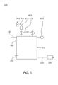
- FIG. 1 is a view illustrating a water storage and discharge apparatus according to an embodiment of the present invention.
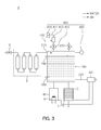
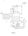
- FIGS. 2 through 4 are views illustrating an operation of the water storage and discharge apparatus provided in a water purifier according to an embodiment of the present invention.
- Embodiments related to the present invention are based on enabling a storage tank to maintain a level of pressure equal to or higher than atmospheric pressure to allow water stored in the storage tank to be expelled or dispensed to the outside regardless of a height of a discharge member such as a cock, a faucet, or the like.
- a water storage and discharge apparatus 100 may include a storage tank 200, a discharge member 300, and a pressure maintenance means 400.
- an inlet pipe 210 may be connected to the storage tank 200.
- the inlet pipe 210 may be connected to a water source (not shown).
- water supplied from the water source may be introduced to and stored in the storage tank 200.
- the water source may be a filter unit F including a plurality of water purifying filters to filter introduced water. Water filtered by the filter unit F may be introduced to the storage tank 200 through the inlet pipe 210 and stored therein.
- the water source is not limited to the filter unit F as illustrated and any device that may be connected to the inlet pipe 210 to supply water may be used as a water source.
- an outlet pipe 220 may be connected to the storage tank 200. Water stored in the storage tank 200 may flow out through the outlet pipe 220. Also, an air vent valve 230 may be connected to the storage tank 200 as shown in the embodiment illustrated in FIG. 1 . When water is introduced to the storage tank 200, air present in the storage tank 200 may be expelled by the air vent valve 230. Accordingly, water may be smoothly introduced to the storage tank 200 through the inlet pipe 210. As shown in the illustrated embodiment, a full water level sensor 240 and a low water level sensor 250 are provided to sense a full water level and a low water level of the storage tank 200.
- the discharge member 300 may be connected to the outlet pipe 220.
- water stored in the storage tank 200 flowing out through the outlet pipe 220 may be dispensed through the discharge member 300 so as to be supplied to a user.
- the discharge member 300 may be a cock, a faucet, or the like.
- the discharge member 300 is not limited thereto and any element which is connected to the outlet pipe 220 and dispenses water stored in the storage tank 200 to the user may be used as the discharge member.
- the pressure maintenance means 400 may include a pump 410 connected to the storage tank 200 and a pressure sensor 420 sensing a pressure within the storage tank 200.
- a pressure equal to or higher than atmospheric pressure may be maintained in the storage tank 200 by means of the pressure maintenance means 400.
- water may be dispensed through the discharge member 300.
- the pressure sensor 420 may be configured to externally indicate a sensed pressure within the storage tank 200.
- the pressure sensor 420 may be configured to externally indicate a sensed pressure within the storage tank 200 by rotating a hand (or a needle) or externally indicate a number corresponding to a sensed pressure within the storage tank 200.
- a user may be able to ascertain a pressure within the storage tank 200 by the pressure sensor 420 having the foregoing configuration.
- the pump 410 may be a hand pump. Accordingly, ambient air may be passively supplied to the storage tank 200 by the user.
- the user may manually operate the pump 410. Then, ambient air may be supplied to the storage tank 200 according to the user's operation of the pump 410 to increase pressure within the storage tank 200 to atmospheric pressure, the predetermined pressure or higher.
- the water storage and discharge apparatus 100 may further include a controller (not shown).
- the controller may be electrically connected to the pump 410 and the pressure sensor 420.
- the controller may operate the pump 410 according to the pressure of the interior of the storage tank 200 sensed by the pressure sensor 420.
- the pump 410 may be an automatic pump operated by the controller to supply ambient air to the storage tank 200.
- the controller may operate the pump 410.
- ambient air may be supplied to the storage tank 200 according to the operation of the pump 410 by the controller to increase the pressure of the interior of the storage tank 200 to atmospheric pressure or the predetermined pressure or higher.
- the pump 410 and the storage tank 200 may be connected by the air supply pipe 411.
- a check valve 412 may be provided in the air supply pipe 411. By the presence of the check valve 412, air may be supplied to the storage tank 200 from the outside, but air may not be expelled to the outside from the storage tank 200. Thus, air may be smoothly supplied to the storage tank 200 by virtue of the pump 410.
- an air filter 413 for filtering air may be provided in the air supply pipe 411.
- air filter 413 for filtering air may be provided in the air supply pipe 411.
- the water storage and discharge apparatus 100 according to an embodiment of the present invention is provided in the water purifier P
- the inlet pipe 210 of the storage tank 200 is connected to the filter unit F of the water purifier P which includes a plurality of water purifying filters to filter introduced water.
- the storage tank 200 may be connected to a hot water storage tank W having a heater H to heat introduced water or a cold water storage tank C having an evaporator E to cool introduced heat.
- a hot water storage tank W having a heater H to heat introduced water or a cold water storage tank C having an evaporator E to cool introduced heat water stored in the storage tank 200, water heated by the hot water storage tank W, or water cooled in the cold water storage tank C may be dispensed to the outside through the discharge member 300 by the single pump 410.
- an ionized water storage tank (not shown), or the like, may also be connected to the storage tank 200.
- an opening and closing valve (V) is opened by the user or the controller (not shown) connected to the low water level sensor 250. Accordingly, as illustrated in FIG. 2 , water is introduced to the filter unit F and filtered by the plurality of water purifying filters included in the filter unit F. The filtered water is introduced to the storage tank 200 through the inlet pipe 210 connected to the filter unit F and stored therein. As described above and illustrated in FIG. 2 , while water introduced through the inlet pipe 210 is stored in the storage tank 200, the air vent valve 230 connected to the storage tank 200 is kept open by the user or the controller. Accordingly, air present in the storage tank 200 is expelled to the outside, and thus, water may be smoothly introduced to the storage tank 200 through the inlet pipe 210.
- water introduced to and stored in the storage tank 200 may be introduced to the hot water storage tank W so as to be heated by the heater H or may be introduced to the cold water storage tank C so as to be cooled by the evaporator E.
- the full water level sensor 240 senses it. Accordingly, the opening and closing valve V and the air vent valve 230 are shut by the user or a controller connected to the full water level sensor 240.
- the pump 410 When a pressure of the interior of the storage tank 200 indicated or sensed by the pressure sensor 420 is below atmospheric pressure or a predetermined pressure, the pump 410 is operated by the user or the controller. Accordingly, ambient air is supplied into the storage tank 200 as illustrated in FIG. 3 . Accordingly, the pressure within the storage tank 200 is increased. When the increased pressure within the storage tank 200 reaches atmospheric pressure or the predetermined pressure or higher, it is indicated or sensed by the pressure sensor 420. Then, the user or the controller stops operation of the pump 410. Thus, the pressure within the storage tank 200 may be equal to or higher than atmospheric pressure or the predetermined pressure.
- the check valve 412 may be provided in the air supply pipe 411 connecting the pump 410 and the storage tank 200.
- the air supply pipe 411 may include the air filter 413.
- the ambient air may be filtered by the air filter 413 and supplied to the storage tank 200.
- external contaminants cannot be introduced to the storage tank 200, and thus, the storage tank 200 can be prevented from being contaminated.
- water stored in the storage tank 200 may be dispensed to the outside through the discharge member 300 by the pressure of the interior of the storage tank 200 so as to be supplied to the user.
- water heated in the hot water storage tank W or water cooled in the cold water storage tank C may also be dispensed by the pressure of the interior of the storage tank 200 to the outside through the discharge member 300 and supplied to the user.
- a pressure of the storage tank 200 sensed by the pressure sensor 420 may be lower than atmospheric pressure or the predetermined pressure.
- the pump 410 is operated by the user or the controller to supply ambient air to the storage tank 200 to increase the pressure of the interior of the storage tank 200 to atmospheric pressure or the predetermined pressure or higher. Accordingly, water stored in the storage tank 200, water heated in the hot water storage tank W, or water cooled in the cold water storage tank C may be dispensed through the discharge member 300, regardless of the height of the discharge member 300.
- stored water may be dispensed to the outside irrespective of the height of the discharge member 300 such as a cock, a faucet, or the like, and thus, the height of the discharge member 300 such as a cock, a faucet, or the like, may be freely set and the discharge member 300 such as a cock, a faucet, or the like, may be positioned at a convenient height for the user.
- water stored in the storage tank 200 may be dispensed by the single pump 410 and product unit cost can be reduced.
- the water storage and discharge apparatus as described above is not limited in its application of configurations and methods, but the entirety or a portion of the embodiments may selectively be combined to be configured to have various forms.
Landscapes
- Life Sciences & Earth Sciences (AREA)
- Hydrology & Water Resources (AREA)
- Engineering & Computer Science (AREA)
- Environmental & Geological Engineering (AREA)
- Water Supply & Treatment (AREA)
- Chemical & Material Sciences (AREA)
- Organic Chemistry (AREA)
- Devices For Dispensing Beverages (AREA)
- Water Treatment By Sorption (AREA)
Applications Claiming Priority (2)
| Application Number | Priority Date | Filing Date | Title |
|---|---|---|---|
| KR1020100028643A KR20110109088A (ko) | 2010-03-30 | 2010-03-30 | 물 저장 및 배출장치 |
| PCT/KR2010/006610 WO2011122747A1 (fr) | 2010-03-30 | 2010-09-29 | Appareil de stockage et de décharge d'eau |
Publications (2)
| Publication Number | Publication Date |
|---|---|
| EP2554232A1 true EP2554232A1 (fr) | 2013-02-06 |
| EP2554232A4 EP2554232A4 (fr) | 2017-11-08 |
Family
ID=44712415
Family Applications (1)
| Application Number | Title | Priority Date | Filing Date |
|---|---|---|---|
| EP10849069.9A Withdrawn EP2554232A4 (fr) | 2010-03-30 | 2010-09-29 | Appareil de stockage et de décharge d'eau |
Country Status (5)
| Country | Link |
|---|---|
| US (1) | US20130026195A1 (fr) |
| EP (1) | EP2554232A4 (fr) |
| KR (1) | KR20110109088A (fr) |
| CN (1) | CN102958578A (fr) |
| WO (1) | WO2011122747A1 (fr) |
Cited By (1)
| Publication number | Priority date | Publication date | Assignee | Title |
|---|---|---|---|---|
| EP3684580A4 (fr) * | 2017-09-22 | 2021-06-23 | Murray, Howard | Baril d'eau |
Families Citing this family (14)
| Publication number | Priority date | Publication date | Assignee | Title |
|---|---|---|---|---|
| TWI554697B (zh) * | 2013-06-11 | 2016-10-21 | 三菱麗陽股份有限公司 | 淨水系統以及淨水系統所使用的切換閥 |
| US20160201943A1 (en) * | 2015-01-09 | 2016-07-14 | Terry Wayne Alsberg | Heated Water Storage Tank with Integral Trapped Air to Mitigate Expansion/Contraction |
| CN104556306B (zh) * | 2015-01-22 | 2016-06-08 | 上海开能环保设备股份有限公司 | 反渗透制水机 |
| KR101642355B1 (ko) * | 2016-01-05 | 2016-07-27 | 심원섭 | 여과 침투수 취수 시스템 및 이를 시공하는 방법 |
| US10590634B2 (en) * | 2016-03-16 | 2020-03-17 | Goodrich Corporation | Pressurized potable water system with conformal shape water storage tank |
| GB2567572B (en) * | 2016-05-13 | 2020-07-15 | Lynntech Inc | A device for changing the amount of oxygen in ambient air |
| CN106830484A (zh) * | 2017-03-01 | 2017-06-13 | 台州河云机械有限公司 | 一种洗手饮水一体机 |
| CN108316392A (zh) * | 2018-01-08 | 2018-07-24 | 珠海格力电器股份有限公司 | 供水系统 |
| CN109354087A (zh) * | 2018-12-19 | 2019-02-19 | 珠海格力电器股份有限公司 | 储液装置、水处理系统及净水设备 |
| CN109354088A (zh) * | 2018-12-19 | 2019-02-19 | 珠海格力电器股份有限公司 | 储水装置、水处理系统及其控制方法 |
| CN110002387B (zh) * | 2019-04-09 | 2024-04-02 | 北京古点科技有限公司 | 一种消除气泡装置及饮料机 |
| CN112835390A (zh) * | 2021-03-03 | 2021-05-25 | 中航工业南航(深圳)测控技术有限公司 | 高分辨率微压流动状态调压装置 |
| KR102321592B1 (ko) * | 2021-05-03 | 2021-11-04 | 명성희 | 공기 가압식 정수기 |
| WO2023178362A2 (fr) * | 2022-03-18 | 2023-09-21 | Unique Bavarian Brewery, LLC | Composant de tuyauterie d'un système de brassage |
Family Cites Families (17)
| Publication number | Priority date | Publication date | Assignee | Title |
|---|---|---|---|---|
| US2032722A (en) * | 1934-07-06 | 1936-03-03 | Frank X Schwab | Beer container |
| US4362256A (en) * | 1980-01-25 | 1982-12-07 | Polasek Randolph J | Beverage dispenser |
| CN2034252U (zh) * | 1988-07-11 | 1989-03-15 | 黎冬华 | 全自动冷热自来水机 |
| US5186362A (en) * | 1991-08-19 | 1993-02-16 | Biagi Jr Hugh A | Liquid transfer assembly |
| KR950002572Y1 (ko) * | 1992-09-07 | 1995-04-12 | 이헌조 | 정수기 |
| KR0175893B1 (ko) * | 1996-04-15 | 1999-03-20 | 김광호 | 정수기 제어장치 및 그 제어방법 |
| KR970073674A (ko) * | 1996-05-28 | 1997-12-10 | 김광호 | 정수기의 가압 펌프 제어 장치 |
| KR19980019469U (ko) * | 1996-10-04 | 1998-07-15 | 최강수 | 정수기의 저장수 공급장치 |
| US20020092873A1 (en) * | 2001-01-12 | 2002-07-18 | Garson Grant W. | Beverage tapper having at least two supply lines |
| US7798373B1 (en) * | 2001-03-26 | 2010-09-21 | Food Equipment Technologies Company, Inc. | Airpot beverage dispenser and method |
| CN2471654Y (zh) * | 2001-04-11 | 2002-01-16 | 董蒙 | 便携洗车器 |
| US7410615B2 (en) * | 2002-01-24 | 2008-08-12 | Perkinelmer Las, Inc. | Precision liquid dispensing system |
| CN2658226Y (zh) * | 2003-08-21 | 2004-11-24 | 张友忠 | 家用自动储水器 |
| US7523695B2 (en) * | 2003-12-12 | 2009-04-28 | Keurig, Incorporated | System for dispensing metered volumes of heated water to the brew chamber of a single serve beverage brewer |
| US7640845B2 (en) * | 2005-09-12 | 2010-01-05 | Keurig, Incorporated | Drain for beverage forming machine |
| US8387516B1 (en) * | 2005-12-02 | 2013-03-05 | D. Michael Reynolds | Coffee maker |
| KR100794103B1 (ko) * | 2006-09-15 | 2008-01-10 | 웅진코웨이주식회사 | 압력센서를 구비하는 정수기 |
-
2010
- 2010-03-30 KR KR1020100028643A patent/KR20110109088A/ko unknown
- 2010-09-29 CN CN2010800659428A patent/CN102958578A/zh active Pending
- 2010-09-29 EP EP10849069.9A patent/EP2554232A4/fr not_active Withdrawn
- 2010-09-29 WO PCT/KR2010/006610 patent/WO2011122747A1/fr active Application Filing
- 2010-09-29 US US13/634,761 patent/US20130026195A1/en not_active Abandoned
Non-Patent Citations (1)
| Title |
|---|
| See references of WO2011122747A1 * |
Cited By (1)
| Publication number | Priority date | Publication date | Assignee | Title |
|---|---|---|---|---|
| EP3684580A4 (fr) * | 2017-09-22 | 2021-06-23 | Murray, Howard | Baril d'eau |
Also Published As
| Publication number | Publication date |
|---|---|
| CN102958578A (zh) | 2013-03-06 |
| WO2011122747A1 (fr) | 2011-10-06 |
| US20130026195A1 (en) | 2013-01-31 |
| EP2554232A4 (fr) | 2017-11-08 |
| KR20110109088A (ko) | 2011-10-06 |
Similar Documents
| Publication | Publication Date | Title |
|---|---|---|
| EP2554232A1 (fr) | Appareil de stockage et de décharge d'eau | |
| US9140466B2 (en) | Fluid heating system and instant fluid heating device | |
| US11596874B2 (en) | Water production, filtration and dispensing system | |
| US20130220903A1 (en) | Reverse osmosis negative-ion water dispenser | |
| US8540118B2 (en) | Water dispenser and method of operating it | |
| KR101884736B1 (ko) | 언더 싱크형 먹는물 공급장치 | |
| US20150143830A1 (en) | A refrigerator appliance and a method for monitoring a water filter assembly within the same | |
| CN109416197B (zh) | 具有智能锅炉的水加热系统及其方法 | |
| US11448423B2 (en) | Hot liquid generation module for liquid treatment apparatus | |
| EP1801507A2 (fr) | Dispositif de distribution de liquide chaud et appareil de chauffage pour ce dispositif. | |
| KR20180045754A (ko) | 언더 싱크형 먹는물 공급장치 | |
| US10436730B2 (en) | System and method for sensing oil quality | |
| EP2186772A1 (fr) | Appareil d'approvisionnement en eau | |
| US20150101670A1 (en) | Water heater assembly for a refrigerator appliance and a method for operating the same | |
| US20150110479A1 (en) | Wirelessly operated heating device of hot water dispenser | |
| US9468332B2 (en) | Docking station for a beverage dispenser having a reservoir | |
| US20130270256A1 (en) | Instantaneous water heater | |
| US20110174839A1 (en) | Under counter drinking fountain | |
| EP1715258A3 (fr) | Appareil et système à accumulation de chaleur | |
| EP1878691B1 (fr) | Bidon pour un carbonisateur | |
| US20130209078A1 (en) | Hot beverage dispensing system | |
| JP2023112901A (ja) | 給湯システム | |
| JP2017504481A (ja) | 水濾過のためのシステム及び方法 | |
| JP2015020759A (ja) | 液体供給装置 | |
| KR20160055471A (ko) | 정수기 |
Legal Events
| Date | Code | Title | Description |
|---|---|---|---|
| PUAI | Public reference made under article 153(3) epc to a published international application that has entered the european phase |
Free format text: ORIGINAL CODE: 0009012 |
|
| 17P | Request for examination filed |
Effective date: 20121015 |
|
| AK | Designated contracting states |
Kind code of ref document: A1 Designated state(s): AL AT BE BG CH CY CZ DE DK EE ES FI FR GB GR HR HU IE IS IT LI LT LU LV MC MK MT NL NO PL PT RO SE SI SK SM TR |
|
| DAX | Request for extension of the european patent (deleted) | ||
| RA4 | Supplementary search report drawn up and despatched (corrected) |
Effective date: 20171006 |
|
| RIC1 | Information provided on ipc code assigned before grant |
Ipc: B01D 35/04 20060101AFI20170929BHEP Ipc: C02F 1/00 20060101ALI20170929BHEP Ipc: B67D 1/04 20060101ALI20170929BHEP Ipc: B01D 35/30 20060101ALI20170929BHEP |
|
| STAA | Information on the status of an ep patent application or granted ep patent |
Free format text: STATUS: THE APPLICATION HAS BEEN WITHDRAWN |
|
| 18W | Application withdrawn |
Effective date: 20180206 |