EP2554194A1 - Integrated circuit and medical device using the same - Google Patents
Integrated circuit and medical device using the same Download PDFInfo
- Publication number
- EP2554194A1 EP2554194A1 EP11762581A EP11762581A EP2554194A1 EP 2554194 A1 EP2554194 A1 EP 2554194A1 EP 11762581 A EP11762581 A EP 11762581A EP 11762581 A EP11762581 A EP 11762581A EP 2554194 A1 EP2554194 A1 EP 2554194A1
- Authority
- EP
- European Patent Office
- Prior art keywords
- integrated circuit
- unit
- amplification
- circuit
- signal
- Prior art date
- Legal status (The legal status is an assumption and is not a legal conclusion. Google has not performed a legal analysis and makes no representation as to the accuracy of the status listed.)
- Withdrawn
Links
- 230000003321 amplification Effects 0.000 claims abstract description 105
- 238000003199 nucleic acid amplification method Methods 0.000 claims abstract description 105
- 238000001802 infusion Methods 0.000 claims abstract description 52
- 239000008280 blood Substances 0.000 claims abstract description 50
- 210000004369 blood Anatomy 0.000 claims abstract description 50
- WQZGKKKJIJFFOK-GASJEMHNSA-N Glucose Natural products OC[C@H]1OC(O)[C@H](O)[C@@H](O)[C@@H]1O WQZGKKKJIJFFOK-GASJEMHNSA-N 0.000 claims abstract description 48
- 239000008103 glucose Substances 0.000 claims abstract description 48
- 238000001514 detection method Methods 0.000 claims abstract description 19
- 238000000034 method Methods 0.000 claims abstract description 15
- 230000008569 process Effects 0.000 claims abstract description 9
- 230000006870 function Effects 0.000 claims description 21
- 238000006243 chemical reaction Methods 0.000 claims description 14
- 238000012545 processing Methods 0.000 claims description 12
- 230000000295 complement effect Effects 0.000 claims description 9
- 239000004973 liquid crystal related substance Substances 0.000 claims description 5
- 238000012544 monitoring process Methods 0.000 claims description 3
- 230000017531 blood circulation Effects 0.000 claims 2
- 230000003287 optical effect Effects 0.000 claims 2
- 239000000758 substrate Substances 0.000 description 13
- 230000036772 blood pressure Effects 0.000 description 7
- 239000013078 crystal Substances 0.000 description 6
- 238000009530 blood pressure measurement Methods 0.000 description 5
- 238000004519 manufacturing process Methods 0.000 description 5
- 230000005236 sound signal Effects 0.000 description 5
- 238000005259 measurement Methods 0.000 description 4
- 230000007423 decrease Effects 0.000 description 2
- 238000010586 diagram Methods 0.000 description 2
- 230000000694 effects Effects 0.000 description 2
- 239000012530 fluid Substances 0.000 description 2
- 238000001990 intravenous administration Methods 0.000 description 2
- 230000007246 mechanism Effects 0.000 description 2
- 230000009467 reduction Effects 0.000 description 2
- 108010015776 Glucose oxidase Proteins 0.000 description 1
- 239000004366 Glucose oxidase Substances 0.000 description 1
- 239000002246 antineoplastic agent Substances 0.000 description 1
- 238000013459 approach Methods 0.000 description 1
- 230000008859 change Effects 0.000 description 1
- 239000003153 chemical reaction reagent Substances 0.000 description 1
- 229940044683 chemotherapy drug Drugs 0.000 description 1
- 238000013461 design Methods 0.000 description 1
- 239000003814 drug Substances 0.000 description 1
- 229940079593 drug Drugs 0.000 description 1
- 238000001914 filtration Methods 0.000 description 1
- 239000000446 fuel Substances 0.000 description 1
- 239000003193 general anesthetic agent Substances 0.000 description 1
- 229940116332 glucose oxidase Drugs 0.000 description 1
- 235000019420 glucose oxidase Nutrition 0.000 description 1
- 238000002347 injection Methods 0.000 description 1
- 239000007924 injection Substances 0.000 description 1
- 239000007788 liquid Substances 0.000 description 1
- 230000035764 nutrition Effects 0.000 description 1
- 235000016709 nutrition Nutrition 0.000 description 1
- 230000002093 peripheral effect Effects 0.000 description 1
- 230000008855 peristalsis Effects 0.000 description 1
- 238000003825 pressing Methods 0.000 description 1
- 238000005215 recombination Methods 0.000 description 1
- 230000006798 recombination Effects 0.000 description 1
- 230000004044 response Effects 0.000 description 1
- 238000003860 storage Methods 0.000 description 1
Images





Classifications
-
- A—HUMAN NECESSITIES
- A61—MEDICAL OR VETERINARY SCIENCE; HYGIENE
- A61M—DEVICES FOR INTRODUCING MEDIA INTO, OR ONTO, THE BODY; DEVICES FOR TRANSDUCING BODY MEDIA OR FOR TAKING MEDIA FROM THE BODY; DEVICES FOR PRODUCING OR ENDING SLEEP OR STUPOR
- A61M5/00—Devices for bringing media into the body in a subcutaneous, intra-vascular or intramuscular way; Accessories therefor, e.g. filling or cleaning devices, arm-rests
- A61M5/14—Infusion devices, e.g. infusing by gravity; Blood infusion; Accessories therefor
- A61M5/168—Means for controlling media flow to the body or for metering media to the body, e.g. drip meters, counters ; Monitoring media flow to the body
- A61M5/16831—Monitoring, detecting, signalling or eliminating infusion flow anomalies
-
- A—HUMAN NECESSITIES
- A61—MEDICAL OR VETERINARY SCIENCE; HYGIENE
- A61B—DIAGNOSIS; SURGERY; IDENTIFICATION
- A61B5/00—Measuring for diagnostic purposes; Identification of persons
- A61B5/02—Detecting, measuring or recording for evaluating the cardiovascular system, e.g. pulse, heart rate, blood pressure or blood flow
- A61B5/021—Measuring pressure in heart or blood vessels
- A61B5/022—Measuring pressure in heart or blood vessels by applying pressure to close blood vessels, e.g. against the skin; Ophthalmodynamometers
-
- A—HUMAN NECESSITIES
- A61—MEDICAL OR VETERINARY SCIENCE; HYGIENE
- A61B—DIAGNOSIS; SURGERY; IDENTIFICATION
- A61B5/00—Measuring for diagnostic purposes; Identification of persons
- A61B5/145—Measuring characteristics of blood in vivo, e.g. gas concentration or pH-value ; Measuring characteristics of body fluids or tissues, e.g. interstitial fluid or cerebral tissue
- A61B5/14532—Measuring characteristics of blood in vivo, e.g. gas concentration or pH-value ; Measuring characteristics of body fluids or tissues, e.g. interstitial fluid or cerebral tissue for measuring glucose, e.g. by tissue impedance measurement
-
- A—HUMAN NECESSITIES
- A61—MEDICAL OR VETERINARY SCIENCE; HYGIENE
- A61B—DIAGNOSIS; SURGERY; IDENTIFICATION
- A61B5/00—Measuring for diagnostic purposes; Identification of persons
- A61B5/145—Measuring characteristics of blood in vivo, e.g. gas concentration or pH-value ; Measuring characteristics of body fluids or tissues, e.g. interstitial fluid or cerebral tissue
- A61B5/1455—Measuring characteristics of blood in vivo, e.g. gas concentration or pH-value ; Measuring characteristics of body fluids or tissues, e.g. interstitial fluid or cerebral tissue using optical sensors, e.g. spectral photometrical oximeters
-
- A—HUMAN NECESSITIES
- A61—MEDICAL OR VETERINARY SCIENCE; HYGIENE
- A61M—DEVICES FOR INTRODUCING MEDIA INTO, OR ONTO, THE BODY; DEVICES FOR TRANSDUCING BODY MEDIA OR FOR TAKING MEDIA FROM THE BODY; DEVICES FOR PRODUCING OR ENDING SLEEP OR STUPOR
- A61M5/00—Devices for bringing media into the body in a subcutaneous, intra-vascular or intramuscular way; Accessories therefor, e.g. filling or cleaning devices, arm-rests
- A61M5/14—Infusion devices, e.g. infusing by gravity; Blood infusion; Accessories therefor
- A61M5/142—Pressure infusion, e.g. using pumps
-
- A—HUMAN NECESSITIES
- A61—MEDICAL OR VETERINARY SCIENCE; HYGIENE
- A61M—DEVICES FOR INTRODUCING MEDIA INTO, OR ONTO, THE BODY; DEVICES FOR TRANSDUCING BODY MEDIA OR FOR TAKING MEDIA FROM THE BODY; DEVICES FOR PRODUCING OR ENDING SLEEP OR STUPOR
- A61M5/00—Devices for bringing media into the body in a subcutaneous, intra-vascular or intramuscular way; Accessories therefor, e.g. filling or cleaning devices, arm-rests
- A61M5/14—Infusion devices, e.g. infusing by gravity; Blood infusion; Accessories therefor
- A61M5/168—Means for controlling media flow to the body or for metering media to the body, e.g. drip meters, counters ; Monitoring media flow to the body
- A61M5/172—Means for controlling media flow to the body or for metering media to the body, e.g. drip meters, counters ; Monitoring media flow to the body electrical or electronic
Definitions
- the present invention relates to an integrated circuit and medical devices such as a sphygmomanometer, a blood glucose meter, and a syringe pump and an infusion pump, which use the same.
- a measuring device requires dedicated processing circuits for each physical quantity of measurement or each type of sensors, and this requires a design and manufacture of the dedicated processing circuits according to various sensors, resulting in a high manufacturing cost.
- a technique which seeks communalization and generalization of a processing circuit for a physical quantity sensor, and which provides a small-sized and cheap physical quantity sensor (patent document 1).
- a sensor head and a first electric processing circuit which converts the output of the sensor head into a common electric physical quantity are constituted on one substrate (a second substrate).
- Another substrate (a first substrate) for power supply is constituted, and a second electric processing circuit for processing unified electric physical quantity is constituted on still another substrate (a third substrate).
- An object of the present invention is to overcome the conventional approach and to provide an integrated circuit which can be utilized as a common integrated circuit for a plurality types of medical devices including sensing functions such as a sphygmomanometer, a blood glucose meter, a syringe pump and an infusion pump, whereby manufacturing cost is reduced.
- Another object of the present invention is to provide a sphygmomanometer, a blood glucose meter, a syringe pump, and an infusion pump, which use the above-mentioned integrated circuit.
- An integrated circuit of the present invention includes: an amplification unit which inputs a signal from an external sensor connected to outside of the integrated circuit; and an arithmetic control unit which receives the signal processed by the amplification unit, and performs an arithmetic process for a control of medical devices or a calculation of a detection result according to an internal program, wherein the external sensor connected to outside of the integrated circuit and the internal program corresponding to the external sensor are changed, whereby the integrated circuit can be utilized as a common integrated circuit for a plurality types of medical devices including a sphygmomanometer, a blood glucose meter, a syringe pump, and an infusion pump, according to a difference of external sensors.
- an integrated circuit which can be utilized as a common integrated circuit for a plurality types of medical devices including a sphygmomanometer, a blood glucose meter, a syringe pump and an infusion pump, whereby manufacturing cost is reduced.
- FIG. 1 is a block diagram schematically illustrating a structure of an integrated circuit of the embodiment of the present invention.
- the platform integrated circuit 1 is an integrated circuit (IC) in which any of external sensors connected to outside of the integrated circuit and any of internal programs corresponding to the external sensor are changed, whereby the integrated circuit can be utilized as a common integrated circuit for a plurality types of medical devices including a sphygmomanometer, a blood glucose meter, a syringe pump, and an infusion pump, according to differences of the external sensors.
- the platform integrated circuit 1 is a system LSI which includes an analog circuit and a digital circuit on one chip.
- the platform integrated circuit 1 includes an input unit 20 which receives an analog signal from outside, a control unit 30 including a CPU 31 which serves as an arithmetic control unit, and a memory unit 40.
- the input unit 20 receives a plurality of inputs from outside and outputs a plurality of output signals.
- the input unit 20 includes an amplification unit 200 and an analog input unit 21 other than the amplification unit.
- the amplification unit 200 includes first through third amplification circuits 201, 202 and 203.
- the first amplification circuit 201 is a programmable gain amplifier (PGA) which is an amplification circuit of a differential gain adjustable type capable of adjusting a differential gain.
- the second and the third amplification circuits 202 and 203 are amplification circuits of fixed gain type of which gains are fixed.
- the amplification unit 200 is constituted so that recombination is possible to accommodate inputs from various external sensors, by changing connection relationship between a plurality of amplification circuits 201, 202 and 203 etc. This point is described later.
- a selection unit 91 is provided between the input unit 20 and the control unit 30.
- the selection unit 91 is a multiplexer which subjects various kinds of signals from the amplification unit 200 and other analog input unit 21 to time division multiplexing, and transfers a plurality of signals to the CPU(arithmetic control unit) 31 of the control unit 30 with switching the signals at each predetermined time.
- An analog-to-digital converter (A/Dconverter) 92 is provided which subjects a signal output from the selection unit 91 to analog-to-digital conversion, and the signal from the selection unit 91 is digitized and is transferred to the CPU 31.
- the memory unit 40 includes a ROM 41 and a RAM 42.
- the ROM 41 stores internal programs executed by the CPU 31.
- the RAM42 is used as temporary storage area for various kinds of data, and a working area for various calculations.
- the control unit 30 includes the CPU 31 which serves as the arithmetic control unit, and a digital controller 32.
- the CPU 31 receives the signal from the amplification unit 200 and other analog input units 21, and performs a control of device, or a calculation of a detection result according to the internal program in the memory unit 40.
- the internal programs are stored according to the types of devices from among programs for the sphygmomanometer, for the blood glucose meter, for the syringe pump, and for the infusion pump.
- the digital controller 32 receives a command from the CPU 31, and controls each unit.
- the control unit 30 includes a digital-to-analog converter (DA converter) 33 for converting a digital signal output from the CPU 31 and so on into an analog signal in order to control the differential gain of the above-mentioned first amplification circuit 201 of differential gain adjustable type.
- the differential gain of the first amplification circuit 201 is set to a predetermined value by the signal converted into an analog value by the DA converter 33.
- the platform integrated circuit 1 further includes a power supply unit 50, a clock unit 60, a voice generation unit 70, and an input-output unit 80, other than the above-described components.
- the power supply unit 50 receives an electric power supply from an external power supply, converts it into suitable voltage, and supplies an electric power to each unit in the platform integrated circuit 1.
- the power supply unit 50 includes a DC-DC conversion unit 51, a regulator 52, and a voltage detector 53.
- the DC-DC conversion unit 51 steps up or steps down a voltage of the external power supply 54 so as to be a desired voltage level.
- the regulator 52 receives the voltage from the DC-DC conversion unit 51, and stabilizes it so as to be constant voltage.
- the voltage detector 53 monitors the voltage output from the regulator 52.
- the clock unit 60 generates a clock signal and a timing signal which are necessary for operations of the CPU 31 serving as the arithmetic control unit and other components.
- the clock unit 60 includes, for example, an RTC (real-time clock) 61, a timing generation unit (timing generator) 62, and a PLL (Phase locked loop) 63.
- the RTC 61 and the timing generation unit 62 include calendar functions, and can generate an interrupt signal at the designated time interval or the designated time on the basis of the oscillating frequency (for example, 32 kHz) of a crystal oscillator 65 connected to outside.
- the PLL 63 generates a high-speed clock for operating the CPU 31 from the frequency signal of the crystal oscillator 65.
- a WDT (Watch Dog Timer) 64 may be provided for monitoring the arithmetic control unit (microcomputer) to avoid a runaway.
- the voice generation unit 70 is for outputting a voice from an external audio amplifier and a speaker 303, without using avoice IC which is an expensive component.
- the voice generation unit 70 includes a voice decoder 71 constituted by software, and a digital-to-analog converter (DA converter) 72 for converting the digital data output from the voice decoder 71 into an analog signal.
- the voice IC may be used as the voice generation unit 70.
- the input-output unit 80 includes first through fourth interfaces 81-84, for example.
- the first interface 81 is for communicating with a personal computer and other external system, in order to take data into the personal computer and other external system 85.
- the first interface 81 an interface based on standards of UART (Universal Asynchronous Receiver Transmitter) or USB (Universal Serial Bus) is adoptable.
- the second interface 82 is an interface for communicating with a contactless IC card.
- a FeliCa (registered trademark) interface is adoptable.
- the third interface 83 is an interface for storing data to an external nonvolatile memory 86, such as EEPROM (Electrically Erasable Programmable ROM) and a flash memory.
- EEPROM Electrical Erasable Programmable ROM
- the fourth interface 84 is an interface for communicating with an external battery level indicator (Fuel Gauge) 87.
- an SPI serial peripheral interface
- an I2C Inter-Integrated Circuit
- the platform integrated circuit 1 includes a liquid crystal display driver unit 93 which drives a liquid crystal panel (LCD) 304 in order to display a measurement result or the like on the LCD 304 connected to outside, a buzzer control unit (buzzer controller) 94 for sounding a warning sound (buzzer) from a buzzer 305 connected to outside, and a current driver unit 95 which is a constant current drive circuit for external sensors.
- a liquid crystal display driver unit 93 which drives a liquid crystal panel (LCD) 304 in order to display a measurement result or the like on the LCD 304 connected to outside
- a buzzer control unit (buzzer controller) 94 for sounding a warning sound (buzzer) from a buzzer 305 connected to outside
- a current driver unit 95 which is a constant current drive circuit for external sensors.
- the platform integrated circuit 1 constituted as described above can be utilized as a common integrated circuit for a plurality types of medical devices including the sphygmomanometer, the blood glucose meter, the syringe pump, and the infusion pump, according to differences in the external sensors, by changing any of external sensors connected to an outside of the integrated circuit and any of internal programs corresponding to the external sensor.
- arithmetic controls of the syringe pump and the infusion pump are complicated in comparison with controls of the sphygmomanometer and the blood glucose meter.
- the platform integrated circuit 1 can connect to a step-up controller 100 which serves as a functional complement integrated circuit complementing a part of functions of the CPU 31 (arithmetic control unit).
- the step-up controller 100 is a gate array or an FPGA (field programmable gate array).
- the step-up controller 100 is connectable with a terminal (not illustrated) of the platform integrated circuit 1, and is connected to the CPU 31 through the terminal and internal bus wiring (not illustrated) and the like.
- the step-up controller 100 receives a command from the CPU 31 and performs a part of arithmetic processes, and the CPU 31 and the step-up controller 100 can cooperate to perform the arithmetic control.
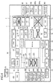
- Respective elements provided in the platform integrated circuit 1 of the embodiment of the present invention described above are classified roughly into a first element group, which is used in common regarding all of the plurality types of medical devices including the sphygmomanometer, the blood glucose meter, the syringe pump and the infusion pump, and a second element group, which is used only regarding a part of the plurality types of medical devices. This point will be described with reference to FIG. 2 through FIG. 6 .
- FIG. 2 is a drawing illustrating a manner of use of the platform integrated circuit in the sphygmomanometer according to the present embodiment.
- FIG. 3 is a drawing illustrating a manner of use of the platform integrated circuit in the blood glucose meter according to the present embodiment.
- FIG. 4 is a drawing illustrating a manner of use of the platform integrated circuit in the syringe pump according to the present embodiment.
- FIG. 5 is a drawing illustrating a manner of use of the platform integrated circuit in the infusion pump according to the present embodiment. In FIG. 2 through FIG. 5 , mark x is presented on each element which is not used by each of devices.
- FIG. 6 is a drawing illustrating the use status for each device with respect to each component.
- the first element group includes: (a) some amplification circuits included in the amplification unit 200, specifically, the first amplification circuit 201 which is a programmable gain amplifier (PGA); (b) the control unit 30 (including the CPU 31 which serves as the arithmetic control unit) ; (c) the memory unit 40; (d) the selection unit 91; (e) the clock unit 60; and (f) some interfaces included in the input-output unit 80, specifically, the first interface 81 for the external system 85 and the third interface 83 for the external nonvolatile memory 86.
- the first element group includes: (a) some amplification circuits included in the amplification unit 200, specifically, the first amplification circuit 201 which is a programmable gain amplifier (PGA); (b) the control unit 30 (including the CPU 31 which serves as the arithmetic control unit) ; (c) the memory unit 40; (d) the selection unit 91; (e) the clock unit 60; and (f) some interfaces included in the input-
- components of the second element group include the following.
- the second element group includes: (g) remaining amplification circuits that are not included in the above-described first element group among the amplification circuits included in the amplification unit 200, specifically, the second amplification circuit 202 and the third amplification circuit 203; (h) the current driver unit 95 which provides current to the external sensor in cases where the platform integrated circuit 1 is used as the integrated circuit for the sphygmomanometer, or the integrated circuit for the blood glucose meter; (i) the internal embedded buzzer control unit 94 and the internal embedded liquid crystal display driver unit (LCD driver unit) 93 which are utilized in cases where the platform integrated circuit 1 is used as the integrated circuit for the sphygmomanometer, or the integrated circuit for the blood glucose meters; (j) the voice generation unit 70 for outputting the voice, in cases where the platform integrated circuit 1 is used as the integrated circuit for the sphygmomanometer, the integrated circuit for the syringe pump, or the integrated circuit
- the platform integrated circuit 1 of the present embodiment can be constituted, in which not only first element group used in common regarding all devices (that is, components as taking the greatest common measure) is made into one chip, but also the second element group is included on the chip.
- Components provided in the platform integrated circuit 1 as components to be used in common regarding some apparatuses of the plurality types of devices such as the sphygmomanometer, the blood glucose meter, the syringe pump, and the infusion pump may be used as elements which have different roles in accordance with the devices.
- the first amplification circuit (PGA) 201 is used in common to the sphygmomanometer, the blood glucose meter, the syringe pump and the infusion pump.
- the first amplification circuit 201 functions as an amplification circuit of a first stage which receives the signal from the external sensor, whereas in cases where the platform integrated circuit 1 is used as the integrated circuit for the blood glucose meter, the first amplification circuit 201 functions as an amplification circuit of the following stage.
- the platform IC constituted as described above can be used as the integrated circuit for the sphygmomanometer, the integrated circuit for the blood glucose meter, the integrated circuit for the syringe pump, and the integrated circuit for the infusion pump, as described later.
- the platform integrated circuit in each devices and operation of the platform IC of the present embodiment.
- FIG. 2 described above is a drawing illustrating a manner of use of the platform integrated circuit in a sphygmomanometer according to the present embodiment.
- the sphygmomanometer 2 is a medical device for measuring human blood pressure.
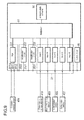
- FIG. 7 is a drawing schematically illustrating a connection relationship to an input unit of the platform integrated circuit in the sphygmomanometer.
- the integrated circuit 1 is provided with, as external electric components, a pressure sensor 301, a microphone unit 302, audio amplifier and speaker 303, an LCD 304, a pump 305, a control valve 306, an exhaust valve 307, a nonvolatile memory 86, and a crystal oscillator 65 and so on.
- the first amplification circuit (PGA) 201 is constituted so as to amplify the difference between the signals input into first input terminal units 2011a and 2011b and output amplified signals to a first output terminal unit 2012.
- the second amplification circuit 202 is constituted so as to amplify the signal input into a second input terminal unit 2021 and output amplified signal to a second output terminal unit2022.
- the third amplification circuit 203 is constituted so as to amplify the signal input into the third input terminal 2031.
- each of the amplification circuits 201 to 203 amplifies the signal input into each of the input terminal units which differ from each other, and outputs amplified signal to each of the output terminal units which differ from each other.
- the first input terminal units 2011a and 2011b, the first output terminal unit 2012, the second input terminal unit 2021, the second output terminal unit 2022, and the third input terminal 2031 are exposed outside, so that the integrated circuit can accommodate each device by changing a connection state to an outside.
- the pressure sensor 301 which detects the pressure of the arm cuff unit through which a subject's upper arm is inserted, is connected to the first input terminal units 2011a and 2011b of the first amplification circuit (PGA) 201 of a differential gain adjustable type, and the first output terminal unit 2012 and the second input terminal unit 2021 of the second amplification circuit are connected through a bandpass filter BPF1 which is a first external circuit.
- PGA first amplification circuit
- an audio signal (detection signal of voltage) is input through a bandpass filter BPF2 from the microphone unit 302 provided at the arm cuff unit into the third amplification circuit 203 and is amplified thereby.
- the control valve 306, the exhaust valve 307, and the pump 305 are connected to the platform integrated circuit 1 so that each part can be driven in response to an instruction from the control unit 30.
- the pressure signal (detection signal) detected by the pressure sensor 301 provided at the arm cuff unit is input into the first amplification circuit (PGA) 201 as an analog differential voltage signal, is applied a differential amplification by the first amplification circuit 201, and after that, is input into the selection unit 91 which is a multiplexer as a signal for one channel. Since the pressure sensor 301 has a variation depend on sensors, it is preferable to set the gain of the first amplification circuit 201 as an amplifier of a first stage to be an appropriate value by the DA converter 33.
- the pressure signal subjected to the differential amplification by the first amplification circuit 201 is amplified and filtered by the bandpass filter BPF1 and the second amplification circuit 202, and after that, is input into the selection unit 91 as a signal for one channel.
- the bandpass filter BPF1 By filtering the pressure signal by the bandpass filter BPF1, it is possible to extract only pulse wave component which can be directly utilized for blood pressure measurement from the pressure signal.
- the pulse wave component can be utilized for oscillometric blood pressure measurement.
- the audio signal (detection signal of voltage) from the microphone unit 302 is amplified and filtered by the bandpass filter BPF2 and the third amplification circuit 203, and after that, is input into the selection unit 91 as a signal for one channel.
- the audio signal from the microphone can be utilized for the blood pressure measurement by a Korotkov's sound method.
- Each of signals of amplified pressure signal, the pulse wave component, and the sound is subjected to a time division multiplexing by the selection unit 91 which is a multiplexer, and is subjected to a digital conversion by the AD converter to provide the CPU 31.
- the CPU 31 instructs the pump 305 to provide air to the arm cuff unit at the time of starting the blood pressure measurement, in accordance with a sphygmomanometer program as an internal program. Moreover, the CPU 31 can store each of signals of the pressure signal which is subjected to the digital conversion, the pulse component, and the audio signal in the nonvolatile memory 86 through the interface 83.
- the CPU 31 determines that the arm cuff unit has been pressurized to predetermined pressure based on the pressure signal which is subjected to the differential amplification by the first amplification circuit (PGA) 201, the CPU 31 controls a drive of the control valve 306 based on the pressure signal so that the air in the arm cuff unit is decompressed at a fixed speed.
- blood-pressure values highest blood pressure and lowest blood pressure
- the measurement result is displayed on the LCD 304.
- the blood-pressure values are calculated by detecting an occurring point of Korotkov's (K) sound and a disappearing point thereof based on the audio signal and the pressure signal. If an exsufflation is required, the CPU 31 controls the exhaust valve 307 to drive.
- FIG. 3 is a drawing illustrating a manner of use of the platform integrated circuit in a blood glucose meter 3 according to the present embodiment.
- the blood glucose meter 3 is for measuring optically a degree of coloration of a (not illustrated) specimen (for example, a paper in which reagents such as glucose oxidase are impregnated) which is colored in accordance with the amount of glucose in blood.
- FIG. 8 is a drawing schematically illustrating a connection relationship to an input unit of the platform integrated circuit in the blood glucose meter.
- the integrated circuit 1 is provided with, as external electric components, a photodiode 309, a light emitting diode 401, a temperature sensor 402 such as a thermistor, the LCD 304, the nonvolatile memory 86, a plug 403 for a contactless IC card, the buzzer 305, and the crystal oscillator 65.
- the photodiode 309 for measuring optically a degree of coloration of an examination part which is colored in accordance with the amount of glucose in blood is connected to the second input terminal unit 2021 of the second amplification circuit 202 of a fixed gain type, and the second output terminal unit 2022 and one of the first input terminal units 2011a of the first amplification circuit (PGA) 201 are connected through a low pass filter LPF as a second external circuit. Furthermore, the second output terminal unit 2022 is connected to another of the first input terminal units 2011b of the first amplification circuit (PGA) 201 without passing through the low pass filter LPF.
- the temperature sensor 402 such as the thermistor is connected to the input A which is the input unit.
- the light emitting diode 401 is connected to the current driver unit 95 through a terminal which is not illustrated.
- the light signal amplified by the second amplification circuit 202 is input into the first amplification circuit (PGA) 201 as one of the differential signals, and is input into the first amplification circuit (PGA) 2011 through the low pass filter LPF as another of the differential signals.
- PGA first amplification circuit
- the first amplification circuit 201 amplifies a difference between the light signal input through the low pass filter LPF and the light signal without passing through the low pass filter LPF. Accordingly, it is possible to extract the high-frequency component utilized for measurement of the blood glucose level in the light signals with high precision.
- the signal amplified by the first amplification circuit (PGA) 201 is input into the selection unit 91 as one channel.
- the gain of the first amplification circuit (PGA) 201 is set to an appropriate value by the DA converter 33.
- the CPU 31 detects the degree of coloration based on the signal amplified by the first amplification circuit (PGA) 201, and performs an arithmetic control to calculate a blood glucose level therefrom. At that time, the influence of temperature can be compensated based on the signal from the temperature sensor 402.
- PGA first amplification circuit
- FIG. 4 is a drawing illustrating a manner of use of the platform integrated circuit in the syringe pump 4 according to the present embodiment.
- the syringe pump 4 is an apparatus which sets a syringe, moves a plunger of syringe by slider means driven by a motor, whereby the contents in the syringe is precisely injected into the inside of the body.
- the syringe pump is a medical device which has a main purpose to perform nutrition and blood transfusion to a patient, and to inject medical fluid such as a chemotherapeutic drug and an anesthetic drug in high accuracy for relatively long time in an intensive care unit (ICU) etc. and the syringe pump has a superior function of medical fluid flow control in comparison with other types of pumps.
- FIG. 9 is a drawing schematically illustrating a connection relationship to an input unit of the platform integrated circuit in the syringe pump.
- the integrated circuit 1 is provided with, as external electric components, a motor 405 used as a source of driving the slider means to move the plunger of syringe, an occlusion pressure sensor 406 which detects the occlusion pressure for monitoring the occlusion state of the syringe, a syringe size detector 407 which detects a diameter size of the syringe, a slider position detector 408 for detecting a position of the slider means which is moved, a motor drive voltage detector 409, a power-supply voltage detector 410, audio amplifier and speaker 303, the LCD 304a, the buzzer 305a, the nonvolatile memory 86, and the crystal oscillator 65 and so on.
- the step-up controller 100 for complementing the arithmetic control function of the CPU 31 is connected to the platform integrated circuit 1.
- the occlusion pressure sensor 406 is connected to the first input terminal units 2011a and 2011b of the first amplification circuit (PGA) 201 of a differential gain adjustable type.
- the syringe size detector 407, the slider position detector 408, the motor drive voltage detector 409, and the power-supply voltage detector 410 are connected so that corresponding signals are input into the inputs A to D which are the analog input units 21 of the platform integrated circuit 1, respectively.
- the motor 405 is connected so that the instruction from the CPU 31 and the step-up controller 100 can be received.
- the occlusion pressure detected by the occlusion pressure sensor 406 included in the syringe pump is input into the first amplification circuit 201 as a differential voltage signal (detection signal) to be amplified, and is input into the selection unit 91 as a signal for one channel.
- the gain of the first amplification circuit 201 is set to an appropriate value by the DA converter 33.
- the amplified occlusion pressure and each of signals of power supply voltage, motor drive voltage, slider position detection, and syringe size detection are subjected to a time division multiplexing in the selection unit 91 which is a multiplexer, and are subjected to a digital conversion by the AD converter.
- Each signal which is subjected to the digital conversion is stored in the external nonvolatile memory 86 through the third interface 83 under a control of the CPU 31, and can be utilized as a signal for control of the syringe pump, and a failure detection signal.
- the CPU 31 and the step-up controller 100 calculate the syringe size from the syringe size detection signal in accordance with a program for the syringe pump as the internal program. Then, the plunger of syringe is moved by a feedback control or the like based on the detection result of the slider position, so that a flow amount and an integrated amount become the amounts which the user inputs beforehand for setting. Considering an influence of a change of the occlusion pressure and so on to the feedback control at the time of starting the drive, the CPU 31 and the step-up controller 100, which receives the occlusion pressure signal from the occlusion pressure sensor 406, can also perform a motor control calibration by compensating parameters for the feedback control.
- the occlusion pressure is also used in order to output the failure detection signal.
- An actual f low amount, the integrated amount and so on are detected based on the current slider position.
- Various detection results such as the flow amount, the integrated amount, and the occlusion pressure are displayed on the LCD 304a, and it is alarmed by the buzzer 305a if necessary.
- the functional assignment with the CPU 31 and the step-up controller 100 can be suitably set by the internal program.
- the LCD 304a of the syringe pump and the buzzer 305a it is prefer to set by the internal program so as to use a high-performance buzzer control unit and an LCD driver unit (not illustrated) connected on outside, instead of using the buzzer control unit 94 and the LCD driver unit 93 embedded in the platform integrated circuit 1. This point is same in the case of the infusion pump described later.
- FIG. 5 is a drawing illustrating a manner of use of the platform integrated circuit in the infusion pump 5 according to the present embodiment.
- the infusion pump 5 is an apparatus which performs a liquid supply by peristalsis realized by pressing the periphery surface of the infusion tube to the downstream side one by one by a plurality of fingers provided along a longitudinal direction of the tube. The plurality of fingers is driven by a motor through a drive mechanism.
- Such infusion pump is a medical device for dosing a drug for the patient continuously with a predetermined dosage for intravenous drip per hour, and for example, it is used to give an intravenous drip injection correctly to the patient after an operation.
- FIG. 10 is a drawing schematically illustrating a connection relationship to an input unit of the platform integrated circuit in the infusion pump.
- the integrated circuit 1 is provided with, as external electric components, two occlusion pressure sensors 411a and 411b which detect the occlusion pressure in order to monitor the occlusion state of the infusion tube in a plurality of positions, the motor 412 which drives a drive mechanism for driving the plurality of fingers, the temperature sensors 402 such as the thermistor, the power-supply voltage detector 410, the audio amplifier and speaker 303, the LCD 304a, the buzzer 305a, the nonvolatile memory 86, and the crystal oscillator 65.
- the step-up controller 100 for complementing the arithmetic control function of the CPU 31 is connected to the platform integrated circuit 1.
- the two occlusion pressure sensors 411a and 411b included in the infusion pump are connected to the first input terminal units 2011a and 2011b of the first amplification circuit (PGA) 201 through the switch SW as a differential voltage signal (detection signal).
- the temperature sensor 402 and the power-supply voltage detector 410 are connected so that each signal is input into the inputs A and B which are the analog input units 21 of the platform integrated circuit 1, respectively.
- the motor 412 is connected so that the instruction from the CPU 31 and the step-up controller 100 can be received.
- any one occlusion pressure selected by the switch SW which switches in time or the like, among the occlusion pressure 1 and the occlusion pressure 2 detected by the two occlusion pressure sensors 411a and 411b included in the infusion pump, is input into the first amplification circuit 201 as the differential voltage signal (detection signal), amplified by the first amplification circuit 201, and after that, input into the selection unit 91 which is a multiplexer as a signal for one channel.
- the gain of the first amplification circuit 201 is set to an appropriate value by the DA converter 33.
- the amplified occlusion pressure 1 and 2 and each signal of power supply voltage and temperature are subjected to a time division multiplexing in the selection unit 91 which is a multiplexer, and are subjected to a digital conversion by the AD converter.
- Each signal which is subjected to the digital conversion is stored in the external nonvolatile memory 86 through the third interface 83 under a control of the CPU 31, and can be utilized as a signal for control of the infusion pump, and a failure detection signal.
- the CPU 31 and the step-up controller 100 generate a motor rotation signal so that an infusion is made continuously for a predetermined time (or to be the integrated amount which is predetermined) at a flow per time which is set beforehand by the user, cause the motor to rotate by the rotation signal, and press the external surface of the infusion tube by the fingers according to a rotation of the motor, whereby the flow amount of the infusion is controlled.
- the occlusion pressure 1 and the occlusion pressure 2 obtained from the two occlusion pressure sensors the occlusion on upper stream side and downstream side of the infusion tube are detected, for example, and an alarm display or the like is made according to the pressure when the occlusion is detected.
- the CPU 31 and the step-up controller 100 which receives the detected temperature from the temperature sensor, can also perform the motor control calibration.
- the platform integrated circuit of the embodiment of the present invention can have following effects.
Landscapes
- Health & Medical Sciences (AREA)
- Life Sciences & Earth Sciences (AREA)
- Veterinary Medicine (AREA)
- Engineering & Computer Science (AREA)
- Physics & Mathematics (AREA)
- Biomedical Technology (AREA)
- Heart & Thoracic Surgery (AREA)
- Animal Behavior & Ethology (AREA)
- General Health & Medical Sciences (AREA)
- Public Health (AREA)
- Vascular Medicine (AREA)
- Hematology (AREA)
- Molecular Biology (AREA)
- Surgery (AREA)
- Anesthesiology (AREA)
- Biophysics (AREA)
- Pathology (AREA)
- Medical Informatics (AREA)
- Optics & Photonics (AREA)
- Cardiology (AREA)
- Spectroscopy & Molecular Physics (AREA)
- Ophthalmology & Optometry (AREA)
- Physiology (AREA)
- Emergency Medicine (AREA)
- Measurement Of The Respiration, Hearing Ability, Form, And Blood Characteristics Of Living Organisms (AREA)
- Infusion, Injection, And Reservoir Apparatuses (AREA)
- Measuring Pulse, Heart Rate, Blood Pressure Or Blood Flow (AREA)
Abstract
Description
- The present invention relates to an integrated circuit and medical devices such as a sphygmomanometer, a blood glucose meter, and a syringe pump and an infusion pump, which use the same.
- A measuring device requires dedicated processing circuits for each physical quantity of measurement or each type of sensors, and this requires a design and manufacture of the dedicated processing circuits according to various sensors, resulting in a high manufacturing cost.
- Heretofore, in order to solve such a problem, a technique is proposed which seeks communalization and generalization of a processing circuit for a physical quantity sensor, and which provides a small-sized and cheap physical quantity sensor (patent document 1). According to the technique described in the
patent document 1, a sensor head and a first electric processing circuit which converts the output of the sensor head into a common electric physical quantity are constituted on one substrate (a second substrate). Another substrate (a first substrate) for power supply is constituted, and a second electric processing circuit for processing unified electric physical quantity is constituted on still another substrate (a third substrate). As a result, according to the technique described in thepatent document 1, it is possible to communalize the first and third substrates and to constitute various physical quantity sensors by replacing only the second substrate. - However, in the technique described in the
patent document 1, the components (parts corresponding to the first and second substrates in the above-mentioned patent document 1) which receive the signal from a sensor and amplify the signal have to be constituted on separate substrates in accordance with the sensor heads, and communalization is not achieved. Moreover, in cases where there is a difference in the processing load such as light or heavy according to the types of sensor heads, if it attempts to completely communalize the substrates for processing the unified electric physical quantity, an expensive arithmetic processing circuit is required in order to accommodate the heaviest load, and this requires a communalization into an excessive high-performance substrate as the whole and results in high manufacturing cost on the contrary. - Therefore, heretofore, it is difficult to communalize integrated circuits for products in different categories which have a difference in the structures of the amplification units, each of which receives a signal from a sensor and performs an amplification process, and have different processing loads such as light and heavy. In particular, in the field of medical devices, it is just intended to make into one chip only the products in the limited categories as described in the
patent document 2, and there is no integrated circuit which can be utilized as a common integrated circuit for a plurality of types of devices including a sphygmomanometer, a blood glucose meter, a syringe pump, and an infusion pump. -
- Patent document 1:
JP-B-3203788 - Patent document 2:
JP-A-2001-212098 - An object of the present invention is to overcome the conventional approach and to provide an integrated circuit which can be utilized as a common integrated circuit for a plurality types of medical devices including sensing functions such as a sphygmomanometer, a blood glucose meter, a syringe pump and an infusion pump, whereby manufacturing cost is reduced.
- Another object of the present invention is to provide a sphygmomanometer, a blood glucose meter, a syringe pump, and an infusion pump, which use the above-mentioned integrated circuit.
- The above-described objects of the present invention are achieved by the following means.
- An integrated circuit of the present invention includes: an amplification unit which inputs a signal from an external sensor connected to outside of the integrated circuit; and an arithmetic control unit which receives the signal processed by the amplification unit, and performs an arithmetic process for a control of medical devices or a calculation of a detection result according to an internal program, wherein the external sensor connected to outside of the integrated circuit and the internal program corresponding to the external sensor are changed, whereby the integrated circuit can be utilized as a common integrated circuit for a plurality types of medical devices including a sphygmomanometer, a blood glucose meter, a syringe pump, and an infusion pump, according to a difference of external sensors.
- According to the present invention, there is provided an integrated circuit which can be utilized as a common integrated circuit for a plurality types of medical devices including a sphygmomanometer, a blood glucose meter, a syringe pump and an infusion pump, whereby manufacturing cost is reduced.
-
-
FIG. 1 is a block diagram schematically illustrating a structure of a platform integrated circuit of the embodiment of the present invention. -
FIG. 2 is a drawing illustrating a manner of use of the platform integrated circuit in a sphygmomanometer according to the present embodiment. -
FIG. 3 is a drawing illustrating a manner of use of the platform integrated circuit in a blood glucose meter according to the present embodiment. -
FIG. 4 is a drawing illustrating a manner of use of the platform integrated circuit in a syringe pump according to the present embodiment. -
FIG. 5 is a drawing illustrating a manner of use of the platform integrated circuit in an infusion pump according to the present embodiment. -
FIG. 6 is a drawing illustrating use status for each device with respect to each component. -
FIG. 7 is a drawing schematically illustrating a connection relationship to an input unit of the platform integrated circuit in the sphygmomanometer inFIG. 2 . -
FIG. 8 is a drawing schematically illustrating a connection relationship to an input unit of the platform integrated circuit in the blood glucose meter inFIG. 3 . -
FIG. 9 is a drawing schematically illustrating a connection relationship to an input unit of the platform integrated circuit in the syringe pump inFIG. 4 . -
FIG. 10 is a drawing schematically illustrating a connection relationship to an input unit of the platform integrated circuit in the infusion pump inFIG. 5 . -
FIG. 1 is a block diagram schematically illustrating a structure of an integrated circuit of the embodiment of the present invention. - The platform
integrated circuit 1 is an integrated circuit (IC) in which any of external sensors connected to outside of the integrated circuit and any of internal programs corresponding to the external sensor are changed, whereby the integrated circuit can be utilized as a common integrated circuit for a plurality types of medical devices including a sphygmomanometer, a blood glucose meter, a syringe pump, and an infusion pump, according to differences of the external sensors. The platform integratedcircuit 1 is a system LSI which includes an analog circuit and a digital circuit on one chip. - The platform integrated
circuit 1 includes aninput unit 20 which receives an analog signal from outside, acontrol unit 30 including aCPU 31 which serves as an arithmetic control unit, and amemory unit 40. - The
input unit 20 receives a plurality of inputs from outside and outputs a plurality of output signals. Theinput unit 20 includes anamplification unit 200 and ananalog input unit 21 other than the amplification unit. Theamplification unit 200 includes first throughthird amplification circuits first amplification circuit 201 is a programmable gain amplifier (PGA) which is an amplification circuit of a differential gain adjustable type capable of adjusting a differential gain. The second and thethird amplification circuits amplification unit 200 is constituted so that recombination is possible to accommodate inputs from various external sensors, by changing connection relationship between a plurality ofamplification circuits - A
selection unit 91 is provided between theinput unit 20 and thecontrol unit 30. Theselection unit 91 is a multiplexer which subjects various kinds of signals from theamplification unit 200 and otheranalog input unit 21 to time division multiplexing, and transfers a plurality of signals to the CPU(arithmetic control unit) 31 of thecontrol unit 30 with switching the signals at each predetermined time. An analog-to-digital converter (A/Dconverter) 92 is provided which subjects a signal output from theselection unit 91 to analog-to-digital conversion, and the signal from theselection unit 91 is digitized and is transferred to theCPU 31. - The
memory unit 40 includes aROM 41 and aRAM 42. TheROM 41 stores internal programs executed by theCPU 31. The RAM42 is used as temporary storage area for various kinds of data, and a working area for various calculations. - The
control unit 30 includes theCPU 31 which serves as the arithmetic control unit, and adigital controller 32. TheCPU 31 receives the signal from theamplification unit 200 and otheranalog input units 21, and performs a control of device, or a calculation of a detection result according to the internal program in thememory unit 40. The internal programs are stored according to the types of devices from among programs for the sphygmomanometer, for the blood glucose meter, for the syringe pump, and for the infusion pump. Thedigital controller 32 receives a command from theCPU 31, and controls each unit. Thecontrol unit 30 includes a digital-to-analog converter (DA converter) 33 for converting a digital signal output from theCPU 31 and so on into an analog signal in order to control the differential gain of the above-mentionedfirst amplification circuit 201 of differential gain adjustable type. The differential gain of thefirst amplification circuit 201 is set to a predetermined value by the signal converted into an analog value by theDA converter 33. - The platform integrated
circuit 1 further includes apower supply unit 50, aclock unit 60, avoice generation unit 70, and an input-output unit 80, other than the above-described components. - The
power supply unit 50 receives an electric power supply from an external power supply, converts it into suitable voltage, and supplies an electric power to each unit in the platform integratedcircuit 1. Thepower supply unit 50 includes a DC-DC conversion unit 51, aregulator 52, and avoltage detector 53. The DC-DC conversion unit 51 steps up or steps down a voltage of theexternal power supply 54 so as to be a desired voltage level. Theregulator 52 receives the voltage from the DC-DC conversion unit 51, and stabilizes it so as to be constant voltage. Thevoltage detector 53 monitors the voltage output from theregulator 52. - The
clock unit 60 generates a clock signal and a timing signal which are necessary for operations of theCPU 31 serving as the arithmetic control unit and other components. Theclock unit 60 includes, for example, an RTC (real-time clock) 61, a timing generation unit (timing generator) 62, and a PLL (Phase locked loop) 63. - The
RTC 61 and thetiming generation unit 62 include calendar functions, and can generate an interrupt signal at the designated time interval or the designated time on the basis of the oscillating frequency (for example, 32 kHz) of acrystal oscillator 65 connected to outside. ThePLL 63 generates a high-speed clock for operating theCPU 31 from the frequency signal of thecrystal oscillator 65. Furthermore, a WDT (Watch Dog Timer) 64 may be provided for monitoring the arithmetic control unit (microcomputer) to avoid a runaway. - The
voice generation unit 70 is for outputting a voice from an external audio amplifier and aspeaker 303, without using avoice IC which is an expensive component. Specifically, thevoice generation unit 70 includes avoice decoder 71 constituted by software, and a digital-to-analog converter (DA converter) 72 for converting the digital data output from thevoice decoder 71 into an analog signal. Unlike the present embodiment, the voice IC may be used as thevoice generation unit 70. - The input-
output unit 80 includes first through fourth interfaces 81-84, for example. Thefirst interface 81 is for communicating with a personal computer and other external system, in order to take data into the personal computer and otherexternal system 85. For example, as thefirst interface 81, an interface based on standards of UART (Universal Asynchronous Receiver Transmitter) or USB (Universal Serial Bus) is adoptable. Thesecond interface 82 is an interface for communicating with a contactless IC card. For example, as thesecond interface 82, a FeliCa (registered trademark) interface is adoptable. Thethird interface 83 is an interface for storing data to an externalnonvolatile memory 86, such as EEPROM (Electrically Erasable Programmable ROM) and a flash memory. Thefourth interface 84 is an interface for communicating with an external battery level indicator (Fuel Gauge) 87. As the third andfourth interfaces - Furthermore, the platform integrated
circuit 1 includes a liquid crystaldisplay driver unit 93 which drives a liquid crystal panel (LCD) 304 in order to display a measurement result or the like on theLCD 304 connected to outside, a buzzer control unit (buzzer controller) 94 for sounding a warning sound (buzzer) from abuzzer 305 connected to outside, and acurrent driver unit 95 which is a constant current drive circuit for external sensors. - The platform integrated
circuit 1 constituted as described above can be utilized as a common integrated circuit for a plurality types of medical devices including the sphygmomanometer, the blood glucose meter, the syringe pump, and the infusion pump, according to differences in the external sensors, by changing any of external sensors connected to an outside of the integrated circuit and any of internal programs corresponding to the external sensor. However, arithmetic controls of the syringe pump and the infusion pump are complicated in comparison with controls of the sphygmomanometer and the blood glucose meter. Therefore, in cases where the platform integratedcircuit 1 is used as the integrated circuit for the syringe pump, or the integrated circuit for the infusion pump, the platform integratedcircuit 1 can connect to a step-upcontroller 100 which serves as a functional complement integrated circuit complementing a part of functions of the CPU 31 (arithmetic control unit). The step-upcontroller 100 is a gate array or an FPGA (field programmable gate array). The step-upcontroller 100 is connectable with a terminal (not illustrated) of the platform integratedcircuit 1, and is connected to theCPU 31 through the terminal and internal bus wiring (not illustrated) and the like. As a result, the step-upcontroller 100 receives a command from theCPU 31 and performs a part of arithmetic processes, and theCPU 31 and the step-upcontroller 100 can cooperate to perform the arithmetic control. - Respective elements provided in the platform integrated
circuit 1 of the embodiment of the present invention described above, are classified roughly into a first element group, which is used in common regarding all of the plurality types of medical devices including the sphygmomanometer, the blood glucose meter, the syringe pump and the infusion pump, and a second element group, which is used only regarding a part of the plurality types of medical devices. This point will be described with reference toFIG. 2 through FIG. 6 . -
FIG. 2 is a drawing illustrating a manner of use of the platform integrated circuit in the sphygmomanometer according to the present embodiment.FIG. 3 is a drawing illustrating a manner of use of the platform integrated circuit in the blood glucose meter according to the present embodiment.FIG. 4 is a drawing illustrating a manner of use of the platform integrated circuit in the syringe pump according to the present embodiment.FIG. 5 is a drawing illustrating a manner of use of the platform integrated circuit in the infusion pump according to the present embodiment. InFIG. 2 through FIG. 5 , mark x is presented on each element which is not used by each of devices.FIG. 6 is a drawing illustrating the use status for each device with respect to each component. - As illustrated in
FIG. 6 , components included in the first element group which is used in common regarding all devices include following components. Specifically, the first element group includes: (a) some amplification circuits included in theamplification unit 200, specifically, thefirst amplification circuit 201 which is a programmable gain amplifier (PGA); (b) the control unit 30 (including theCPU 31 which serves as the arithmetic control unit) ; (c) thememory unit 40; (d) theselection unit 91; (e) theclock unit 60; and (f) some interfaces included in the input-output unit 80, specifically, thefirst interface 81 for theexternal system 85 and thethird interface 83 for the externalnonvolatile memory 86. - On the other hand, components of the second element group include the following. Specifically, the second element group includes: (g) remaining amplification circuits that are not included in the above-described first element group among the amplification circuits included in the amplification unit 200, specifically, the second amplification circuit 202 and the third amplification circuit 203; (h) the current driver unit 95 which provides current to the external sensor in cases where the platform integrated circuit 1 is used as the integrated circuit for the sphygmomanometer, or the integrated circuit for the blood glucose meter; (i) the internal embedded buzzer control unit 94 and the internal embedded liquid crystal display driver unit (LCD driver unit) 93 which are utilized in cases where the platform integrated circuit 1 is used as the integrated circuit for the sphygmomanometer, or the integrated circuit for the blood glucose meters; (j) the voice generation unit 70 for outputting the voice, in cases where the platform integrated circuit 1 is used as the integrated circuit for the sphygmomanometer, the integrated circuit for the syringe pump, or the integrated circuit for the infusion pump; and (k) the remaining interfaces that are not included in the above-described first element group among the interfaces included in the input-output unit 80, specifically the second interface 82 for the contactless IC card, and the fourth interface 84 for the battery level indicator.
- In this way, the platform integrated
circuit 1 of the present embodiment can be constituted, in which not only first element group used in common regarding all devices (that is, components as taking the greatest common measure) is made into one chip, but also the second element group is included on the chip. - Although an LCD and a buzzer (alarm) are provided in the
syringe pump 4 or theinfusion pump 5 as illustrated inFIG. 4 andFIG. 5 , it is not necessary to use thebuzzer control unit 94 and theLCD driver unit 93 embedded in the platform integratedcircuit 1 for theseLCD 304a andbuzzer 305a, and a high-performance buzzer control unit and an LCD driver unit (not illustrated) connected on outside may be used. On the other hand, for theLCD 304 in the sphygmomanometer and the blood glucose meter, and thebuzzer 305 in the sphygmomanometer, thebuzzer control unit 94 and theLCD driver unit 93 embedded in the platform integratedcircuit 1 are used. - In this way, in accordance with the types of devices (that is, in accordance with the internal programs), such as the sphygmomanometer, the blood glucose meter, the syringe pump and the infusion pump, it is set whether using the internal embedded component (s) provided, or using external connected component which has same type of function as the internal embedded component and has different performance therefrom, as at least one component (in this embodiment, two of the
buzzer control unit 94 and the liquid crystal display driver unit 93) included in the second element group. - Components provided in the platform integrated
circuit 1 as components to be used in common regarding some apparatuses of the plurality types of devices such as the sphygmomanometer, the blood glucose meter, the syringe pump, and the infusion pump may be used as elements which have different roles in accordance with the devices. Specifically, as illustrated inFIG. 6 , the first amplification circuit (PGA) 201 is used in common to the sphygmomanometer, the blood glucose meter, the syringe pump and the infusion pump. However, in cases where the platform integratedcircuit 1 is used as the integrated circuit for the sphygmomanometer, the integrated circuit for the syringe pump, or the integrated circuit for the infusion pump, thefirst amplification circuit 201 functions as an amplification circuit of a first stage which receives the signal from the external sensor, whereas in cases where the platform integratedcircuit 1 is used as the integrated circuit for the blood glucose meter, thefirst amplification circuit 201 functions as an amplification circuit of the following stage. - The platform IC constituted as described above can be used as the integrated circuit for the sphygmomanometer, the integrated circuit for the blood glucose meter, the integrated circuit for the syringe pump, and the integrated circuit for the infusion pump, as described later. Hereinafter, it will be described a manner of use of the platform integrated circuit in each devices and operation of the platform IC of the present embodiment.
-
FIG. 2 described above is a drawing illustrating a manner of use of the platform integrated circuit in a sphygmomanometer according to the present embodiment. Thesphygmomanometer 2 is a medical device for measuring human blood pressure.FIG. 7 is a drawing schematically illustrating a connection relationship to an input unit of the platform integrated circuit in the sphygmomanometer. - With reference to
FIG. 2 , in cases where the platform integratedcircuit 1 is used as the integrated circuit for the sphygmomanometer, theintegrated circuit 1 is provided with, as external electric components, apressure sensor 301, amicrophone unit 302, audio amplifier andspeaker 303, anLCD 304, apump 305, acontrol valve 306, anexhaust valve 307, anonvolatile memory 86, and acrystal oscillator 65 and so on. - As illustrated in
FIG. 7 , in a plurality of amplification circuits (amplifiers) in the embodiment of the present invention, the first amplification circuit (PGA) 201 is constituted so as to amplify the difference between the signals input into firstinput terminal units output terminal unit 2012. Thesecond amplification circuit 202 is constituted so as to amplify the signal input into a secondinput terminal unit 2021 and output amplified signal to a second output terminal unit2022. Thethird amplification circuit 203 is constituted so as to amplify the signal input into thethird input terminal 2031. In this way, each of theamplification circuits 201 to 203 amplifies the signal input into each of the input terminal units which differ from each other, and outputs amplified signal to each of the output terminal units which differ from each other. The firstinput terminal units output terminal unit 2012, the secondinput terminal unit 2021, the secondoutput terminal unit 2022, and thethird input terminal 2031 are exposed outside, so that the integrated circuit can accommodate each device by changing a connection state to an outside. - On the premise of the above structures, it will be described a case of utilizing the platform integrated
circuit 1 as the integrated circuit for the sphygmomanometer. In this case, thepressure sensor 301, which detects the pressure of the arm cuff unit through which a subject's upper arm is inserted, is connected to the firstinput terminal units output terminal unit 2012 and the secondinput terminal unit 2021 of the second amplification circuit are connected through a bandpass filter BPF1 which is a first external circuit. - Moreover, an audio signal (detection signal of voltage) is input through a bandpass filter BPF2 from the
microphone unit 302 provided at the arm cuff unit into thethird amplification circuit 203 and is amplified thereby. Thecontrol valve 306, theexhaust valve 307, and thepump 305 are connected to the platform integratedcircuit 1 so that each part can be driven in response to an instruction from thecontrol unit 30. - In a state where the above-described connection is made, the pressure signal (detection signal) detected by the
pressure sensor 301 provided at the arm cuff unit is input into the first amplification circuit (PGA) 201 as an analog differential voltage signal, is applied a differential amplification by thefirst amplification circuit 201, and after that, is input into theselection unit 91 which is a multiplexer as a signal for one channel. Since thepressure sensor 301 has a variation depend on sensors, it is preferable to set the gain of thefirst amplification circuit 201 as an amplifier of a first stage to be an appropriate value by theDA converter 33. - Furthermore, the pressure signal subjected to the differential amplification by the
first amplification circuit 201 is amplified and filtered by the bandpass filter BPF1 and thesecond amplification circuit 202, and after that, is input into theselection unit 91 as a signal for one channel. By filtering the pressure signal by the bandpass filter BPF1, it is possible to extract only pulse wave component which can be directly utilized for blood pressure measurement from the pressure signal. The pulse wave component can be utilized for oscillometric blood pressure measurement. - On the other hand, the audio signal (detection signal of voltage) from the
microphone unit 302 is amplified and filtered by the bandpass filter BPF2 and thethird amplification circuit 203, and after that, is input into theselection unit 91 as a signal for one channel. The audio signal from the microphone can be utilized for the blood pressure measurement by a Korotkov's sound method. - Each of signals of amplified pressure signal, the pulse wave component, and the sound is subjected to a time division multiplexing by the
selection unit 91 which is a multiplexer, and is subjected to a digital conversion by the AD converter to provide theCPU 31. - The
CPU 31 instructs thepump 305 to provide air to the arm cuff unit at the time of starting the blood pressure measurement, in accordance with a sphygmomanometer program as an internal program. Moreover, theCPU 31 can store each of signals of the pressure signal which is subjected to the digital conversion, the pulse component, and the audio signal in thenonvolatile memory 86 through theinterface 83. - When the
CPU 31 determines that the arm cuff unit has been pressurized to predetermined pressure based on the pressure signal which is subjected to the differential amplification by the first amplification circuit (PGA) 201, theCPU 31 controls a drive of thecontrol valve 306 based on the pressure signal so that the air in the arm cuff unit is decompressed at a fixed speed. When applying the oscillometric blood pressure measurement, blood-pressure values (highest blood pressure and lowest blood pressure) are calculated by detecting a point where the pulse component rapidly increases and a point where the pulse component rapidly decreases based on the signal of the pulse component and the pressure signal, and the measurement result is displayed on theLCD 304. When applying the Korotkov's sound method, the blood-pressure values (highest blood pressure and lowest bloodpressure) are calculated by detecting an occurring point of Korotkov's (K) sound and a disappearing point thereof based on the audio signal and the pressure signal. If an exsufflation is required, theCPU 31 controls theexhaust valve 307 to drive. -
FIG. 3 is a drawing illustrating a manner of use of the platform integrated circuit in a blood glucose meter 3 according to the present embodiment. The blood glucose meter 3 is for measuring optically a degree of coloration of a (not illustrated) specimen (for example, a paper in which reagents such as glucose oxidase are impregnated) which is colored in accordance with the amount of glucose in blood.FIG. 8 is a drawing schematically illustrating a connection relationship to an input unit of the platform integrated circuit in the blood glucose meter. - As illustrated in
FIG. 3 , in cases where the platform integratedcircuit 1 is used as the integrated circuit for the blood glucose meter, theintegrated circuit 1 is provided with, as external electric components, aphotodiode 309, alight emitting diode 401, atemperature sensor 402 such as a thermistor, theLCD 304, thenonvolatile memory 86, aplug 403 for a contactless IC card, thebuzzer 305, and thecrystal oscillator 65. - As illustrated in
FIG. 8 , in cases where the platform integratedcircuit 1 is utilized as the integrated circuit for the blood glucose meter, thephotodiode 309 for measuring optically a degree of coloration of an examination part which is colored in accordance with the amount of glucose in blood is connected to the secondinput terminal unit 2021 of thesecond amplification circuit 202 of a fixed gain type, and the secondoutput terminal unit 2022 and one of the firstinput terminal units 2011a of the first amplification circuit (PGA) 201 are connected through a low pass filter LPF as a second external circuit. Furthermore, the secondoutput terminal unit 2022 is connected to another of the firstinput terminal units 2011b of the first amplification circuit (PGA) 201 without passing through the low pass filter LPF. Thetemperature sensor 402 such as the thermistor is connected to the input A which is the input unit. Thelight emitting diode 401 is connected to thecurrent driver unit 95 through a terminal which is not illustrated. - In a state where the above-described connection is made, current is provided to the
light emitting diode 401 through thecurrent driver unit 95 under a control by theCPU 31 which executes the blood glucose meter program as the internal program. In this way, thelight emitting diode 401 irradiates light to the specimen in which a subj ect' s blood is transfused. At that time, the light signal (detection signal of current) detected by thephotodiode 309 included in the blood glucose meter is subjected to a current / voltage conversion and an amplification by thesecond amplification circuit 202, which constitutes a transimpedance amplifier with an external resistor which is not illustrated, and after that, is input into theselection unit 91 as one channel. - Furthermore, the light signal amplified by the
second amplification circuit 202 is input into the first amplification circuit (PGA) 201 as one of the differential signals, and is input into the first amplification circuit (PGA) 2011 through the low pass filter LPF as another of the differential signals. - The
first amplification circuit 201 amplifies a difference between the light signal input through the low pass filter LPF and the light signal without passing through the low pass filter LPF. Accordingly, it is possible to extract the high-frequency component utilized for measurement of the blood glucose level in the light signals with high precision. The signal amplified by the first amplification circuit (PGA) 201 is input into theselection unit 91 as one channel. The gain of the first amplification circuit (PGA) 201 is set to an appropriate value by theDA converter 33. - In accordance with the blood glucose meter program as the internal program, the
CPU 31 detects the degree of coloration based on the signal amplified by the first amplification circuit (PGA) 201, and performs an arithmetic control to calculate a blood glucose level therefrom. At that time, the influence of temperature can be compensated based on the signal from thetemperature sensor 402. -
FIG. 4 is a drawing illustrating a manner of use of the platform integrated circuit in thesyringe pump 4 according to the present embodiment. Thesyringe pump 4 is an apparatus which sets a syringe, moves a plunger of syringe by slider means driven by a motor, whereby the contents in the syringe is precisely injected into the inside of the body. The syringe pump is a medical device which has a main purpose to perform nutrition and blood transfusion to a patient, and to inject medical fluid such as a chemotherapeutic drug and an anesthetic drug in high accuracy for relatively long time in an intensive care unit (ICU) etc. and the syringe pump has a superior function of medical fluid flow control in comparison with other types of pumps.FIG. 9 is a drawing schematically illustrating a connection relationship to an input unit of the platform integrated circuit in the syringe pump. - As illustrated in
FIG. 4 , in cases where the platform integratedcircuit 1 is used as the integrated circuit for the syringe pump, theintegrated circuit 1 is provided with, as external electric components, amotor 405 used as a source of driving the slider means to move the plunger of syringe, anocclusion pressure sensor 406 which detects the occlusion pressure for monitoring the occlusion state of the syringe, asyringe size detector 407 which detects a diameter size of the syringe, aslider position detector 408 for detecting a position of the slider means which is moved, a motordrive voltage detector 409, a power-supply voltage detector 410, audio amplifier andspeaker 303, theLCD 304a, thebuzzer 305a, thenonvolatile memory 86, and thecrystal oscillator 65 and so on. Moreover, the step-upcontroller 100 for complementing the arithmetic control function of theCPU 31 is connected to the platform integratedcircuit 1. - As illustrated in
FIG. 9 , theocclusion pressure sensor 406 is connected to the firstinput terminal units syringe size detector 407, theslider position detector 408, the motordrive voltage detector 409, and the power-supply voltage detector 410 are connected so that corresponding signals are input into the inputs A to D which are theanalog input units 21 of the platform integratedcircuit 1, respectively. Themotor 405 is connected so that the instruction from theCPU 31 and the step-upcontroller 100 can be received. - In a state where the above-described connection is made, the occlusion pressure detected by the
occlusion pressure sensor 406 included in the syringe pump is input into thefirst amplification circuit 201 as a differential voltage signal (detection signal) to be amplified, and is input into theselection unit 91 as a signal for one channel. The gain of thefirst amplification circuit 201 is set to an appropriate value by theDA converter 33. - The amplified occlusion pressure and each of signals of power supply voltage, motor drive voltage, slider position detection, and syringe size detection are subjected to a time division multiplexing in the
selection unit 91 which is a multiplexer, and are subjected to a digital conversion by the AD converter. Each signal which is subjected to the digital conversion is stored in the externalnonvolatile memory 86 through thethird interface 83 under a control of theCPU 31, and can be utilized as a signal for control of the syringe pump, and a failure detection signal. - Specifically, the
CPU 31 and the step-upcontroller 100 calculate the syringe size from the syringe size detection signal in accordance with a program for the syringe pump as the internal program. Then, the plunger of syringe is moved by a feedback control or the like based on the detection result of the slider position, so that a flow amount and an integrated amount become the amounts which the user inputs beforehand for setting. Considering an influence of a change of the occlusion pressure and so on to the feedback control at the time of starting the drive, theCPU 31 and the step-upcontroller 100, which receives the occlusion pressure signal from theocclusion pressure sensor 406, can also perform a motor control calibration by compensating parameters for the feedback control. Moreover, the occlusion pressure is also used in order to output the failure detection signal. An actual f low amount, the integrated amount and so on are detected based on the current slider position. Various detection results such as the flow amount, the integrated amount, and the occlusion pressure are displayed on theLCD 304a, and it is alarmed by thebuzzer 305a if necessary. The functional assignment with theCPU 31 and the step-upcontroller 100 can be suitably set by the internal program. - Moreover, for the
LCD 304a of the syringe pump and thebuzzer 305a, it is prefer to set by the internal program so as to use a high-performance buzzer control unit and an LCD driver unit (not illustrated) connected on outside, instead of using thebuzzer control unit 94 and theLCD driver unit 93 embedded in the platform integratedcircuit 1. This point is same in the case of the infusion pump described later. -
FIG. 5 is a drawing illustrating a manner of use of the platform integrated circuit in theinfusion pump 5 according to the present embodiment. Theinfusion pump 5 is an apparatus which performs a liquid supply by peristalsis realized by pressing the periphery surface of the infusion tube to the downstream side one by one by a plurality of fingers provided along a longitudinal direction of the tube. The plurality of fingers is driven by a motor through a drive mechanism. Such infusion pump is a medical device for dosing a drug for the patient continuously with a predetermined dosage for intravenous drip per hour, and for example, it is used to give an intravenous drip injection correctly to the patient after an operation.FIG. 10 is a drawing schematically illustrating a connection relationship to an input unit of the platform integrated circuit in the infusion pump. - As illustrated in
FIG. 5 , in cases where the platform integratedcircuit 1 is used as the integrated circuit for the infusion pump, theintegrated circuit 1 is provided with, as external electric components, twoocclusion pressure sensors motor 412 which drives a drive mechanism for driving the plurality of fingers, thetemperature sensors 402 such as the thermistor, the power-supply voltage detector 410, the audio amplifier andspeaker 303, theLCD 304a, thebuzzer 305a, thenonvolatile memory 86, and thecrystal oscillator 65. Moreover, the step-upcontroller 100 for complementing the arithmetic control function of theCPU 31 is connected to the platform integratedcircuit 1. - As illustrated in
FIG. 10 , the twoocclusion pressure sensors input terminal units temperature sensor 402 and the power-supply voltage detector 410 are connected so that each signal is input into the inputs A and B which are theanalog input units 21 of the platform integratedcircuit 1, respectively. Themotor 412 is connected so that the instruction from theCPU 31 and the step-upcontroller 100 can be received. - In a state where the above-described connection is made, any one occlusion pressure, selected by the switch SW which switches in time or the like, among the
occlusion pressure 1 and theocclusion pressure 2 detected by the twoocclusion pressure sensors first amplification circuit 201 as the differential voltage signal (detection signal), amplified by thefirst amplification circuit 201, and after that, input into theselection unit 91 which is a multiplexer as a signal for one channel. The gain of thefirst amplification circuit 201 is set to an appropriate value by theDA converter 33. - The amplified
occlusion pressure selection unit 91 which is a multiplexer, and are subjected to a digital conversion by the AD converter. Each signal which is subjected to the digital conversion is stored in the externalnonvolatile memory 86 through thethird interface 83 under a control of theCPU 31, and can be utilized as a signal for control of the infusion pump, and a failure detection signal. - Specifically, the
CPU 31 and the step-upcontroller 100 generate a motor rotation signal so that an infusion is made continuously for a predetermined time (or to be the integrated amount which is predetermined) at a flow per time which is set beforehand by the user, cause the motor to rotate by the rotation signal, and press the external surface of the infusion tube by the fingers according to a rotation of the motor, whereby the flow amount of the infusion is controlled. Based on theocclusion pressure 1 and theocclusion pressure 2 obtained from the two occlusion pressure sensors, the occlusion on upper stream side and downstream side of the infusion tube are detected, for example, and an alarm display or the like is made according to the pressure when the occlusion is detected. - Considering that a hardness of the external surface of the infusion tube changes according to temperature conditions, the
CPU 31 and the step-upcontroller 100, which receives the detected temperature from the temperature sensor, can also perform the motor control calibration. - As explained above, the platform integrated circuit of the embodiment of the present invention can have following effects.
- (a) According to the platform integrated circuit of the present embodiment, since it can be utilized as a common integrated circuit among a plurality kinds of different medical devices including the sphygmomanometer, the blood glucose meter, the syringe pump and the infusion pump which include a sensing function, it is possible to communalize the components of the plurality kinds of devices, and therefore, it is possible to realize a further cost reduction of the components for devices and the devices using the components.
- (b) According to the platform integrated circuit of the present embodiment, it is possible to make into one chip not only the first element group used in common for all devices of the plurality kinds of different medical devices (components as taking the greatest common measure), but also the second element group used only for some devices. Therefore, since the range of the elements to be implemented by making into one chip is expanded and the number of external components decreases, the size of the overall circuit can be reduced as well as further cost reduction for devices can be realizable.
- (c) According to the platform integrated circuit of the present embodiment, the internal program sets, in accordance with the plurality kinds of medical devices, whether using an internal embedded component or using an external connection component which has the same function as the internal embedded component and has different performance therefrom. Therefore, in cases where different performances of the function are required in accordance with the application of devices, it is not necessary to provide an expensive internal embedded component to accommodate the highest functional performance.
- (d) According to the platform integrated circuit of the present embodiment, the platform integrated circuit includes a plurality of amplification circuits that amplifies the signals input into the input terminal units which are different to each other and outputs the amplified signals to the output terminal units which are different to each other, and a connection status between the input terminal units and the output terminal units is changed in accordance with the type of external sensor selectively connected to the integrated circuit, whereby, among the plurality of amplification circuits, an order can be changed between the amplification circuit of the first stage which receives the signals from the external sensor first, and the amplification circuit of the following stage. Therefore, it is also possible to communalize the input units which are required to different functions according to types of sensor heads.
- (e) According to the platform integrated circuit of the present embodiment, some components such as the
first amplification circuit 201 can be used as elements to serve different functions according to the devices, even if the components are included in the platform integratedcircuit 1 to be used in common regarding some devices among the plurality kinds of different medical devices such as a sphygmomanometer, a blood glucose meter, a syringe pump, and an infusion pump. Therefore, it is possible to reduce necessity for providing separate circuit elements for each different function. - (f) According to the platform integrated circuit of the present embodiment, the platform integrated circuit can be connected to a functional complement integrated circuit which complements a part of functions of an arithmetic control unit in accordance with the type of the plurality kinds of medical devices. Therefore, in cases where there is a difference in the processing load such as light or heavy according to the types of sensor heads, it is not necessary to provide an expensive calculation process circuit to accommodate the heaviest load, and it is possible to avoid a communalization into an excessive high-performance substrate as the whole.
- The integrated circuit and the sphygmomanometer, the blood glucose meter, the syringe pump, and the infusion pump which use the integrated circuit according to the embodiments of the present invention has been explained, but the present invention is not limited to the above-described embodiments. Amodification, an addition and an omission can be made suitably within a scope of invention without departing from the technical idea of the claims.
- This application is based on the Japanese patent application No.
2010-080209, filed on March 31, 2010 -
- 1
- platform integrated circuit,
- 2
- sphygmomanometer,
- 3
- blood glucose meter,
- 4
- syringe pump,
- 5
- infusion pump,
- 20
- input unit,
- 30
- control unit,
- 31
- CPU (arithmetic control unit),
- 40
- memory unit,
- 50
- power supply unit,
- 60
- clock unit,
- 70
- voice generation unit,
- 80
- input-output unit,
- 91
- selection unit,
- 95
- current driver unit,
- 93
- LCD driver,
- 94
- buzzer control unit,
- 100
- step-up controller (functional complement integrated circuit),
- 200
- amplification unit,
- 201
- first amplification circuit (PGA),
- 202
- second amplification circuit,
- 203
- third amplification circuit,
- 301
- pressure sensor (external sensor),
- 302
- microphone unit (external sensor),
- 306
- photodiode (external sensor),
- 406, 411a, b
- occlusion pressure sensor (external sensor),
- 2011a, b
- first input terminal,
- 2012
- first output terminal,
- 2021
- second input terminal,
- 2022
- second output terminal, and
- 2031
- third input terminal.
Claims (15)
- An integrated circuit comprising:an amplification unit which inputs a signal from an external sensor connected to outside of the integrated circuit; andan arithmetic control unit which receives the signal processed by the amplification unit, and performs an arithmetic process for a control of medical devices or a calculation of a detection result according to an internal program,wherein the external sensor connected to outside of the integrated circuit and the internal program corresponding to the external sensor are changed, whereby the integrated circuit can be utilized as a common integrated circuit for a plurality types of different medical devices including a sphygmomanometer, a blood glucose meter, a syringe pump, and an infusion pump, according to a difference of external sensors.
- The integrated circuit as claimed in claim 1, wherein the integrated circuit interiorly includes:a first element group used in common regarding all of the plurality types of different medical devices; anda second element group used only regarding a part of the plurality types of different medical devices.
- The integrated circuit as claimed in claim 2, wherein
in accordance with a type among the plurality types of medical devices, the internal program sets whether to use an internal embedded component provided as at least one component in the second element group, or using an external connected component which has the same kind of function as that of the internal embedded component and has a different performance from that of the internal embedded component. - The integrated circuit as claimed in claim 2 or 3, wherein the first element group includes:(a) at least a part of amplification circuits included in the amplification unit;(b) the arithmetic control unit;(c) a memory unit which stores the internal program;(d) a selection unit which is provided between the amplification unit and the arithmetic control unit, and transfers various kinds of signals from the amplification unit and other analog input to the arithmetic control unit while switching the various kinds of signals with a predetermined cycle;(e) a clock unit which generates a clock signal and a timing signal for the arithmetic control unit;(f) at least a part of interfaces included in an input-output unit for communicating with outside; and(g) a power supply unit which receives electric power supply from outside and provides the electric power to each part of the integrated circuit.
- The integrated circuit as claimed in claim 4, wherein the second element group includes:(h) remaining amplification circuits which are not included in the first element, in the amplification units;(i) a current driver unit which provides current to the external sensor in cases where the integrated circuit is used as the integrated circuit for the sphygmomanometer, or the integrated circuit for the blood glucose meter;(j) an internal embedded buzzer control unit and an internal embedded liquid crystal display driver unit which are utilized in cases where the integrated circuit is used as the integrated circuit for the sphygmomanometer, or the integrated circuit for the blood glucose meter;(k) a voice generation unit for outputting a voice, in cases where the integrated circuit is used as the integrated circuit for the sphygmomanometer, the integrated circuit for the syringe pump, or the integrated circuit for the infusion pump; and(l) remaining interfaces which are not included in the first element group, in the input-output units for communicating with outside.
- The integrated circuit as claimed in any one of claims 1 to 5, wherein
the amplification unit includes a plurality of amplification circuits which amplify the signals input into different input terminal units and output amplified signals to different output terminal units, and
connections between the input terminal units and the output terminal units are changed in accordance with the type of the external sensor selectively connected to the integrated circuit, and thus an order of the amplification circuit of a first stage which receives the signal from the external sensor first and the amplification circuits of following stages can be switched among the plurality of the amplification circuits. - The integrated circuit as claimed in claim 6, wherein the amplification unit includes:a first amplification circuit of a differential gain adjustable type, which processes the signal input into a first input terminal unit and outputs the signal to a first output terminal unit;a second amplification circuit of a fixed gain type, which processes the signal input into a second input terminal unit and outputs the signal to a second output terminal unit; anda third amplification circuit of a fixed gain type, which processes the signal input into a third input terminal unit and outputs the signal, whereinin cases where the integrated circuit is utilized as the integrated circuit for the sphygmomanometer, a pressure sensor detecting a pressure of an arm cuff unit, into which a subject's upper arm is inserted, is connected to the first input terminal unit of the first amplification circuit of the differential gain adjustable type, the first output terminal unit and the second input terminal unit are connected through a first external circuit whereas a microphone unit detecting a sound of blood-flow in the upper arm is connected to the third input terminal unit, and output signals generated by the first amplification circuit, the second amplification circuit and the third amplification circuit respectively are subjected to analog-to-digital conversion to be provided to the arithmetic control unit,in cases where the integrated circuit is utilized as the integrated circuit for the blood glucose meter, an optical sensor for measuring optically a degree of coloration of examination part which is colored in accordance with the amount of glucose in blood is connected to the second input terminal unit of the second amplification circuit of the fixed gain type, the second output terminal unit and the first input terminal unit are connected through the second external circuit, and output signals generated by the first amplification circuit and the second amplification circuit respectively are subjected to the analog-to-digital conversion to be provided to the arithmetic control unit, andin cases where the integrated circuit is utilized as the integrated circuit for the syringe pump, or the integrated circuit for the infusion pump, an occlusion pressure sensor monitoring an occlusion state of a syringe or an infusion tube is connected to the first input terminal unit of the first amplification circuit of the differential gain adjustable type, and an output signal generated by the first amplification circuit is subjected to the analog-to-digital conversion to be provided to the arithmetic control unit.
- The integrated circuit as claimed in any one of claims 1 to 7, wherein the integrated circuit is capable of connecting to a functional complement integrated circuit which complements a part of functions of the arithmetic control unit according to a type among the plurality types of medical devices.
- The integrated circuit as claimed in claim 8, wherein
the integrated circuit is a system LSI in which an analog circuit and a digital circuit are mixed, and
the functional complement integrated circuit is a gate array or a field programmable gate array. - The integrated circuit as claimed in claim 8 or 9, wherein
the functional complement integrated circuit complements arithmetic functions of the integrated circuit by a parallel processing with the arithmetic control unit. - The integrated circuit as claimed in any one of claims 8 to 10, wherein
in cases where the integrated circuit is used as the integrated circuit for the syringe pump or the integrated circuit for the infusion pump, the functional complement integrated circuit is connected. - A sphygmomanometer comprising:the integrated circuit as claimed in any one of claims 1 to 11,wherein the sphygmomanometer further comprises, as the external sensor,a pressure sensor which detects pressure of an arm cuff unit for inserting a subject's upper arm, anda microphone unit which detects a sound of blood-flow in the upper arm.
- A blood glucose meter comprising:the integrated circuit as claimed in any one of claims 1 to 11;an optical sensor, as the external sensor, for measuring optically a degree of coloration of examination part which is colored in accordance with the amount of glucose in blood.
- A syringe pump comprising:the integrated circuit as claimed in any one of claims 8 to 11;the functional complement integrated circuit which is connected to the integrated circuit and complements a part of functions of the arithmetic control unit; andan occlusion pressure sensor, as the external sensor, which monitors the occlusion state of a syringe.
- A infusion pump comprising:the integrated circuit as claimed in any one of claims 8 to 11;the functional complement integrated circuit which is connected to the integrated circuit and complements the part of functions of the arithmetic control unit; andan occlusion pressure sensor, as the external sensor, which monitors the occlusion state of an infusion tube.
Applications Claiming Priority (2)
| Application Number | Priority Date | Filing Date | Title |
|---|---|---|---|
| JP2010080209A JP2011212045A (en) | 2010-03-31 | 2010-03-31 | Integrated circuit and medical equipment using the same |
| PCT/JP2011/056217 WO2011122343A1 (en) | 2010-03-31 | 2011-03-16 | Integrated circuit and medical device using the same |
Publications (2)
| Publication Number | Publication Date |
|---|---|
| EP2554194A1 true EP2554194A1 (en) | 2013-02-06 |
| EP2554194A4 EP2554194A4 (en) | 2015-12-02 |
Family
ID=44712061
Family Applications (1)
| Application Number | Title | Priority Date | Filing Date |
|---|---|---|---|
| EP11762581.4A Withdrawn EP2554194A4 (en) | 2010-03-31 | 2011-03-16 | Integrated circuit and medical device using the same |
Country Status (4)
| Country | Link |
|---|---|
| EP (1) | EP2554194A4 (en) |
| JP (1) | JP2011212045A (en) |
| CN (1) | CN102985123A (en) |
| WO (1) | WO2011122343A1 (en) |
Cited By (1)
| Publication number | Priority date | Publication date | Assignee | Title |
|---|---|---|---|---|
| US10216677B2 (en) | 2015-12-24 | 2019-02-26 | Samsung Electronics Co., Ltd. | Electronic apparatus and control method thereof with identification of sensor using history |
Families Citing this family (3)
| Publication number | Priority date | Publication date | Assignee | Title |
|---|---|---|---|---|
| CN103969696A (en) * | 2014-02-19 | 2014-08-06 | 苏州泽德医疗器械有限公司 | Injection pump detecting method and device |
| CN104089662A (en) * | 2014-07-28 | 2014-10-08 | 成都千嘉科技有限公司 | Pressure acquisition system based on flow measurement device |
| JP6720532B2 (en) * | 2016-01-06 | 2020-07-08 | セイコーエプソン株式会社 | Circuit devices, oscillators, electronic devices and mobile units |
Family Cites Families (9)
| Publication number | Priority date | Publication date | Assignee | Title |
|---|---|---|---|---|
| EP0145208A1 (en) * | 1983-11-04 | 1985-06-19 | SEIKO INSTRUMENTS & ELECTRONICS LTD. | An electronic sphygmomanometer |
| US6689091B2 (en) * | 1996-08-02 | 2004-02-10 | Tuan Bui | Medical apparatus with remote control |
| JPH1080401A (en) * | 1996-09-09 | 1998-03-31 | Fukuda Denshi Co Ltd | Sphygmomanometer with ECG analysis function |
| US20060206356A1 (en) * | 2005-03-09 | 2006-09-14 | Vanderveen Timothy W | Line verification for multi-pump arrays |
| JP2005253999A (en) * | 2005-05-20 | 2005-09-22 | Terumo Corp | Infusion pump |
| SG130951A1 (en) * | 2005-09-13 | 2007-04-26 | Glucostats System Pte Ltd | An arrangement for providing a constant contact pressure for a probe |
| JP4805724B2 (en) * | 2006-05-16 | 2011-11-02 | テルモ株式会社 | Syringe pump |
| JP2010080209A (en) | 2008-09-25 | 2010-04-08 | Nec Corp | Small-sized electronic device |
| CN101884529B (en) * | 2009-05-15 | 2012-03-21 | 深圳市鑫汇科科技有限公司 | Electronic sphygmomanometer and calibration method thereof |
-
2010
- 2010-03-31 JP JP2010080209A patent/JP2011212045A/en active Pending
-
2011
- 2011-03-16 CN CN2011800177218A patent/CN102985123A/en active Pending
- 2011-03-16 WO PCT/JP2011/056217 patent/WO2011122343A1/en not_active Ceased
- 2011-03-16 EP EP11762581.4A patent/EP2554194A4/en not_active Withdrawn
Non-Patent Citations (1)
| Title |
|---|
| See references of WO2011122343A1 * |
Cited By (1)
| Publication number | Priority date | Publication date | Assignee | Title |
|---|---|---|---|---|
| US10216677B2 (en) | 2015-12-24 | 2019-02-26 | Samsung Electronics Co., Ltd. | Electronic apparatus and control method thereof with identification of sensor using history |
Also Published As
| Publication number | Publication date |
|---|---|
| JP2011212045A (en) | 2011-10-27 |
| EP2554194A4 (en) | 2015-12-02 |
| CN102985123A (en) | 2013-03-20 |
| WO2011122343A1 (en) | 2011-10-06 |
Similar Documents
| Publication | Publication Date | Title |
|---|---|---|
| US12016664B2 (en) | System and method for controlling a valve of a portable medical device | |
| CN112584763B (en) | Measuring device | |
| CN102639053B (en) | Electronic sphygmomanometer | |
| CN110301907A (en) | A kind of wearable pulse wave detection device and blood pressure detecting method | |
| EP4400037A1 (en) | Electronic sphygmomanometer with integrated air pump and control method thereof | |
| WO2011122343A1 (en) | Integrated circuit and medical device using the same | |
| CN109259744B (en) | High-precision in-vivo pressure monitor | |
| WO2009143111A1 (en) | Medical system having a medical unit and a display monitor | |
| EP2554193B1 (en) | Integrated circuit and medical instrument using same | |
| CN218552325U (en) | Wearable device and wearable system | |
| US12207945B2 (en) | Wearable cardiovascular monitoring device | |
| CN205197978U (en) | Individuation blood pressure does not have wound detection device | |
| CN205041388U (en) | Sphygmomanometry apparatus | |
| US20220152292A1 (en) | Automatic pressure control device, system, and method | |
| WO2020112548A1 (en) | Method and device for manual entry of vertical height difference between measurement site and heart level for non-invasive blood pressure monitor | |
| US20240277269A1 (en) | State machine calibration | |
| CN206745352U (en) | Electronic sphygmomanometer | |
| WO2025194252A1 (en) | Devices and methods for measurement of intravascular pressure | |
| CN201937670U (en) | Mobile phone with sphygmomanometer function | |
| CN204500661U (en) | The portable continuous dynamic monitoring electronic sphygomanometer of disease prevention | |
| CN117136029A (en) | Biological information measurement device and control method of biological information measurement device | |
| Sathya et al. | Estimation and Detection of Blood Pressure Using Smart Phones without Using Cuff | |
| CN107115110A (en) | A kind of type vibration wire survey meter of blood pressure | |
| CN105054920A (en) | Blood pressure measurement instrument |
Legal Events
| Date | Code | Title | Description |
|---|---|---|---|
| PUAI | Public reference made under article 153(3) epc to a published international application that has entered the european phase |
Free format text: ORIGINAL CODE: 0009012 |
|
| 17P | Request for examination filed |
Effective date: 20120928 |
|
| AK | Designated contracting states |
Kind code of ref document: A1 Designated state(s): AL AT BE BG CH CY CZ DE DK EE ES FI FR GB GR HR HU IE IS IT LI LT LU LV MC MK MT NL NO PL PT RO RS SE SI SK SM TR |
|
| DAX | Request for extension of the european patent (deleted) | ||
| RA4 | Supplementary search report drawn up and despatched (corrected) |
Effective date: 20151104 |
|
| RIC1 | Information provided on ipc code assigned before grant |
Ipc: A61B 5/1455 20060101ALI20151029BHEP Ipc: A61B 5/022 20060101ALI20151029BHEP Ipc: A61M 5/168 20060101ALI20151029BHEP Ipc: A61M 5/00 20060101ALI20151029BHEP Ipc: A61B 5/145 20060101ALI20151029BHEP Ipc: A61M 5/172 20060101ALI20151029BHEP Ipc: A61M 5/142 20060101AFI20151029BHEP |
|
| STAA | Information on the status of an ep patent application or granted ep patent |
Free format text: STATUS: THE APPLICATION IS DEEMED TO BE WITHDRAWN |
|
| 18D | Application deemed to be withdrawn |
Effective date: 20160531 |