EP2554150A1 - Walking aid device - Google Patents
Walking aid device Download PDFInfo
- Publication number
- EP2554150A1 EP2554150A1 EP10849399A EP10849399A EP2554150A1 EP 2554150 A1 EP2554150 A1 EP 2554150A1 EP 10849399 A EP10849399 A EP 10849399A EP 10849399 A EP10849399 A EP 10849399A EP 2554150 A1 EP2554150 A1 EP 2554150A1
- Authority
- EP
- European Patent Office
- Prior art keywords
- unit
- members
- replaceable
- shank
- user
- Prior art date
- Legal status (The legal status is an assumption and is not a legal conclusion. Google has not performed a legal analysis and makes no representation as to the accuracy of the status listed.)
- Granted
Links
- 210000003127 knee Anatomy 0.000 claims abstract description 48
- 210000002683 foot Anatomy 0.000 claims abstract description 47
- 210000000689 upper leg Anatomy 0.000 claims abstract description 40
- 210000003423 ankle Anatomy 0.000 claims abstract description 29
- 239000000463 material Substances 0.000 claims description 20
- 239000007769 metal material Substances 0.000 claims description 12
- 238000000034 method Methods 0.000 claims description 9
- 239000004918 carbon fiber reinforced polymer Substances 0.000 description 13
- 229910052782 aluminium Inorganic materials 0.000 description 12
- XAGFODPZIPBFFR-UHFFFAOYSA-N aluminium Chemical compound [Al] XAGFODPZIPBFFR-UHFFFAOYSA-N 0.000 description 12
- 210000002414 leg Anatomy 0.000 description 6
- 230000005484 gravity Effects 0.000 description 3
- 229910052751 metal Inorganic materials 0.000 description 3
- 239000002184 metal Substances 0.000 description 3
- 238000001514 detection method Methods 0.000 description 2
- 230000015572 biosynthetic process Effects 0.000 description 1
- 230000008878 coupling Effects 0.000 description 1
- 238000010168 coupling process Methods 0.000 description 1
- 238000005859 coupling reaction Methods 0.000 description 1
- 238000012986 modification Methods 0.000 description 1
- 230000004048 modification Effects 0.000 description 1
Images


Classifications
-
- A—HUMAN NECESSITIES
- A61—MEDICAL OR VETERINARY SCIENCE; HYGIENE
- A61H—PHYSICAL THERAPY APPARATUS, e.g. DEVICES FOR LOCATING OR STIMULATING REFLEX POINTS IN THE BODY; ARTIFICIAL RESPIRATION; MASSAGE; BATHING DEVICES FOR SPECIAL THERAPEUTIC OR HYGIENIC PURPOSES OR SPECIFIC PARTS OF THE BODY
- A61H3/00—Appliances for aiding patients or disabled persons to walk about
-
- A—HUMAN NECESSITIES
- A61—MEDICAL OR VETERINARY SCIENCE; HYGIENE
- A61H—PHYSICAL THERAPY APPARATUS, e.g. DEVICES FOR LOCATING OR STIMULATING REFLEX POINTS IN THE BODY; ARTIFICIAL RESPIRATION; MASSAGE; BATHING DEVICES FOR SPECIAL THERAPEUTIC OR HYGIENIC PURPOSES OR SPECIFIC PARTS OF THE BODY
- A61H1/00—Apparatus for passive exercising; Vibrating apparatus ; Chiropractic devices, e.g. body impacting devices, external devices for briefly extending or aligning unbroken bones
- A61H1/02—Stretching or bending or torsioning apparatus for exercising
- A61H1/0237—Stretching or bending or torsioning apparatus for exercising for the lower limbs
- A61H1/024—Knee
-
- A—HUMAN NECESSITIES
- A61—MEDICAL OR VETERINARY SCIENCE; HYGIENE
- A61H—PHYSICAL THERAPY APPARATUS, e.g. DEVICES FOR LOCATING OR STIMULATING REFLEX POINTS IN THE BODY; ARTIFICIAL RESPIRATION; MASSAGE; BATHING DEVICES FOR SPECIAL THERAPEUTIC OR HYGIENIC PURPOSES OR SPECIFIC PARTS OF THE BODY
- A61H2201/00—Characteristics of apparatus not provided for in the preceding codes
- A61H2201/01—Constructive details
- A61H2201/0192—Specific means for adjusting dimensions
-
- A—HUMAN NECESSITIES
- A61—MEDICAL OR VETERINARY SCIENCE; HYGIENE
- A61H—PHYSICAL THERAPY APPARATUS, e.g. DEVICES FOR LOCATING OR STIMULATING REFLEX POINTS IN THE BODY; ARTIFICIAL RESPIRATION; MASSAGE; BATHING DEVICES FOR SPECIAL THERAPEUTIC OR HYGIENIC PURPOSES OR SPECIFIC PARTS OF THE BODY
- A61H2201/00—Characteristics of apparatus not provided for in the preceding codes
- A61H2201/16—Physical interface with patient
- A61H2201/1602—Physical interface with patient kind of interface, e.g. head rest, knee support or lumbar support
- A61H2201/165—Wearable interfaces
-
- A—HUMAN NECESSITIES
- A61—MEDICAL OR VETERINARY SCIENCE; HYGIENE
- A61H—PHYSICAL THERAPY APPARATUS, e.g. DEVICES FOR LOCATING OR STIMULATING REFLEX POINTS IN THE BODY; ARTIFICIAL RESPIRATION; MASSAGE; BATHING DEVICES FOR SPECIAL THERAPEUTIC OR HYGIENIC PURPOSES OR SPECIFIC PARTS OF THE BODY
- A61H2201/00—Characteristics of apparatus not provided for in the preceding codes
- A61H2201/50—Control means thereof
- A61H2201/5058—Sensors or detectors
- A61H2201/5069—Angle sensors
Definitions
- the present invention relates to a walk assistance device for assisting a person to walk; in particular, the present invention relates to a walk assistance device fitted to a person's leg.
- a walk assistance device is taught in Japanese Unexamined Patent Application Publication No. 09-173398 (below, Patent Document 1).
- the walk assistance device is configured to be capable of being fitted to a person's leg, and can assist the person to walk by adjusting the movement of the leg.
- the walk assistance device comprises a thigh unit arranged on a thigh, a shank unit arranged on a shank, a foot unit arranged on a foot, and a knee position joint unit coupling the thigh unit and the shank unit in a swingable manner.
- This type of walk assistance device is preferably adjustable in size to conform to the physical constitution of the user to whom it is fitted. Consequently, in e.g. the walk assistance device of Patent Document 1, the length of the shank unit is configured to be adjustable by fastening an upper portion and a lower portion of the shank unit by a bolt, and by having a bolt hole be a long hole. According to this configuration, the length of the shank unit can be adjusted by small breadth in accordance with the physical constitution of the user.
- the above configuration requires the long hole to be formed in the shank unit, leading to a loss of strength in the shank unit. Further, since the direction in which force is applied to the shank unit is substantially the same as the longitudinal direction of the long hole, the bolt may move along the long hole when strong force is applied to the shank unit, inadvertently changing the length of the shank unit.
- the present invention presents a technique that allows the size adjustment of a walk assistance device without requiring the formation of the long hole.
- the present invention is realized in a walk assistance device for assisting a user to walk.
- This walk assistance device comprises a thigh unit configured to be arranged on a thigh of the user, a shank unit configured to be arranged on a shank of the user, a foot unit configured to be arranged on a foot of the user, a knee position joint unit configured to couple the thigh unit and the shank unit in a swingable manner, and an ankle position joint unit configured to couple the shank unit and the foot unit in a swingable manner.
- the shank unit comprises a first replaceable member and a second replaceable member that extend along the shank of the user, and a length of the shank unit is adjustable by replacing each of the first and second replaceable members with another one having a different length.
- This walk assistance device has a configuration in which the length of the shank unit is adjustable by replacing the first and second replaceable members. According to this configuration, a long hole need not be formed in the shank unit, allowing loss of strength of shank unit to be avoided. Further, the length of the shank unit does not change even if strong force is applied to the shank unit, allowing the walking of the user to be assisted stably.
- the length of the shank unit can be adjusted in multistep lengths by combining the first replaceable member and the second replaceable member. For example, in case the length of the shank unit were to be adjusted using only the first replaceable member, 30 pieces of first replaceable members having different lengths would need to be prepared for adjusting the length of the shank unit by 30 steps.
- the length of the shank unit can be adjusted by, e,g., 30 steps by simply preparing a total of 13 pieces of replaceable members: 10 pieces of first replaceable members having different lengths and 3 pieces of second replaceable members having different lengths.
- the first replaceable member and the second replaceable member may be formed from the same material or different material.
- the replaceable member having a higher density is shorter than the replaceable member having a lower density. That is, if the first replaceable member has the higher density than the second replaceable member, it is preferred that the first replaceable member is shorter than the second replaceable member.
- the first replaceable member has the higher density than the second replaceable member
- the center of gravity of the shank unit is located closer to the knee position joint unit, allowing the moment of inertia of the shank unit to be smaller relative to the knee position joint unit. Thereby, the burden on the user and the load on the knee position joint unit can be reduced.
- the first replaceable member is preferably made of metal material
- the second replaceable member is preferably made of fiber-reinforced material. Since processing of the metal material is generally easy, if the first replaceable member is made of metal material, a variety of first replaceable members can be prepared at low cost. On the other hand, since fiber-reinforced material generally has a high specific strength, if the second replaceable member is made of the fiber-reinforced material, the weight of the shank unit can be significantly reduced while its strength is ensured.
- first replaceable members and second replaceable members can be prepared at comparatively low cost.
- the foot unit may comprise a sole member configured to be arranged on a sole and a third replaceable member extending from the sole member to the ankle position joint unit, and a distance from the sole member to the ankle position joint unit may be adjustable by replacing the third replaceable member with another one having a different length. According to this configuration, the location of the ankle position joint unit relative to the ankle of the user can be adjusted without forming a long hole in the foot unit.
- the present invention presents a method for adjusting size of the walk assistance device
- This adjusting method comprises preparing a plurality of the first replaceable members having lengths different from each other and a plurality of the second replaceable members having lengths different from each other, selecting one of the first replaceable members and one of the second replaceable members in accordance with a physical constitution of the user, and assembling the shank unit of the walk assistance device by using the selected first and second members.
- the length of the shank unit is adjustable in multistep lengths by a variety of combinations of the first and second members which are selected, and the number of the multistep lengths is larger than the total number of the pluralities of first and second members which are prepared.
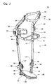
- Fig. 1 is a perspective view showing a walk assistance device 10 of the embodiment.
- the walk assistance device 10 is fitted to a leg 100 of a user, and is a device for assisting that user to walk.
- the walk assistance device 10 is used, e.g., for the functional rehabilitation of a user who has difficultly in walking independently.
- the walk assistance device 10 is fitted to the dysfunctional leg of the user, and assists the user in walking by actively adjusting the movement of the leg.
- the walk assistance device 10 comprises a thigh unit 20 arranged on a thigh 102 of the user, a shank unit 40 arranged on a shank 104 of the user, and a foot unit 60 arranged on a foot 106 of the user. Further, the walk assistance device 10 comprises a pair of knee position joint units 30 that couples the thigh unit 20 and the shank unit 40 in a swingable manner, and a pair of ankle position joint units 50 that couples the shank unit 40 and the foot unit 60 in a swingable manner. The pair of knee position joint units 30 holds a knee 103 of the user therebetween, and is arranged coaxially with the knee 103.
- one of the knee position joint units 30 is arranged coaxially with the knee 103 at the outside of the knee 103, and the other knee position joint unit 30 is arranged coaxially with the knee 103 at the inside of the knee 103.
- the pair of ankle position joint units 50 holds an ankle 105 of the user therebetween, and is arranged coaxially with the ankle 105. That is, one of the ankle position joint units 50 is arranged coaxially with the ankle 105 at the outside of the ankle 105, and the other ankle position joint unit 50 is arranged coaxially with the ankle 105 at the inside of the ankle 105.
- the walk assistance device 10 further comprises a control unit 70, a drive unit 80 and a sensor unit 90.
- the control unit 70 is provided on the thigh unit 20, the drive unit 80 is provided on the knee position joint units 30, and the sensor unit 90 is provided on the ankle position joint units 50.
- the drive unit 80 houses a motor, decelerator, and sensors, and can drive the knee position joint units 30. That is, the drive unit 80 can swing the shank unit 40 relative to the thigh unit 20.
- the sensor unit 90 has various types of sensors, and can detect the angle of the ankle position joint units 50 and whether the foot unit 60 is making contact with the ground.
- the control unit 70 has a small computer and a battery, and is electrically connected to the drive unit 80 and the sensor unit 90.
- the control unit 70 inputs detection signals from the sensor unit 90, and controls the operation of the drive unit 80 based on the detection signals that were input.
- the operation of the walk assistance device 10 is adjusted over time in accordance with the actual walking of the user.
- Fig. 2 shows a perspective view of the frame structure of the walk assistance device 10.
- the thigh unit 20 comprises a thigh plate member 22, a pair of thigh pillar members 24 and a pair of thigh base members 26.
- the thigh plate member 22 is arranged at the front of the thigh 102 of the user.
- the thigh plate member 22 has a pad and a belt (not shown), and is fixed firmly to the thigh 102 of the user by the belt.
- the thigh 102 of the user is fastened firmly to the thigh plate member 22 by the belt.
- the thigh 102 of the user is maintained such that it cannot move longitudinally, horizontally or vertically relative to the thigh plate member 22.
- the thigh plate member 22 is supported by the pair of thigh pillar members 24.
- the thigh pillar members 24 are affixed to the thigh base members 26, and the thigh base members 26 are affixed to the knee position joint units 30.
- the thigh plate member 22 and the thigh pillar members 24 of the present embodiment are made of carbon fiber reinforced plastic (CFRP).
- CFRP carbon fiber reinforced plastic
- Carbon fiber reinforced plastic is a type of the fiber-reinforced material and has a high specific strength. Consequently, the weight of the thigh plate member 22 and the thigh pillar members 24 can be reduced by the carbon fiber reinforced plastic that is a type of the fiber-reinforced material.
- Fig. 3 shows an exploded view of the frame structure of the shank unit 40.
- the shank unit 40 comprises a pair of knee-side base members 42, a knee plate member 43, a pair of first pillar members 44, a pair of second pillar members 46 and a pair of ankle-side base members 48.
- the knee plate member 43 is arranged at the front of the knee 103 of the user, and makes contact from the front with a lower portion of the knee 103 of the user (i.e., an upper portion of the shank 104).
- the knee plate member 43 is supported by the pair of knee-side base members 42.
- the shank unit 40 does not make contact with the shank 104 of the user. That is, the shank 104 of the user is supported only from the front by the knee plate member 43 of the shank unit 40.
- the knee-side base members 42 are L-shaped plate members.
- the knee-side base members 42 are made of metal material; specifically, of aluminum.
- One of the knee-side base members 42 is affixed to one of the knee position joint units 30 at the outside of the shank 104 of the user, and the other knee-side base member 42 is affixed to the other knee position joint unit 30 at the inside of the shank 104 of the user. That is, the knee-side base members 42 are coupled in a swingable manner to the thigh base members 26 via the knee position joint units 30.
- the knee plate member 43 is attached to end parts located at the front of the knee-side base members 42.
- the first pillar members 44 are long and narrow plate members.
- the first pillar members 44 are made of the metal material; specifically, of aluminum.
- One of the first pillar members 44 is located at the outside of the shank 104 of the user, and an upper end of that first pillar member 44 is affixed to one of the knee-side base members 42.
- the other of the first pillar members 44 is located at the inside of the shank 104 of the user, and an upper end of that first pillar member 44 is affixed to the other of the knee-side base members 42.
- Each first pillar member 44 extends downward along the shank 104 of the user, and an upper end of each second pillar member 46 is affixed to a lower end of each first pillar member 44.
- the first pillar members 44 are first replaceable members that can be replaced in accordance with the physical constitution of the user. That is, in the walk assistance device 10 of the present embodiment, the size (length) of the shank unit 40 can be adjusted by replacing the first pillar member 44 with another one having a different size (length).
- the second pillar members 46 are rod-shaped members.
- the second pillar members 46 are made of the fiber-reinforced material; specifically, of carbon fiber reinforced plastic (CFRP). However, a metal fitting 47 made of metal material (specifically, aluminum) is provided at both ends of the second pillar members 46.
- One of the second pillar members 46 is located at the outside of the shank 104 of the user, and an upper end of that second pillar member 46 is affixed to one of the first pillar members 44.
- the other second pillar member 46 is located at the inside of the shank 104 of the user, and an upper end of that second pillar member 46 is affixed to the other first pillar members 44.
- Each second pillar member 46 extends downward along the shank 104 of the user, and a lower end of each second pillar member 46 is affixed to one respective ankle-side base member 48.
- the second pillar members 46 are second replaceable members that can be replaced in accordance with the physical constitution of the user. That is, in the walk assistance device 10 of the present embodiment, the size (length) of the shank unit 40 can also be adjusted by replacing the second pillar member 46 with another one having a different size (length).
- the ankle-side base members 48 are plate members.
- the ankle-side base members 48 are made of metal material; specifically, of aluminum.
- One of the ankle-side base members 48 is affixed to one of the ankle position joint units 50 at the outside of the shank 104 of the user, and the other ankle-side base member 48 is affixed to the other ankle position joint unit 50 at the inside of the shank 104 of the user.
- the first pillar members 44 and the second pillar members 46 are replaceable members that can be replaced in accordance with the physical constitution of the user. Consequently, as shown in Fig. 3 , the first pillar members 44 and the second pillar members 46 are fixed by bolts 12, 14, 16 and are configured to be easily replaceable.
- the upper ends of the first pillar members 44 are affixed to the knee-side base members 42 by a plurality of the bolts 12.
- the upper ends of the second pillar members 46 are affixed to the lower ends of the first pillar members 44 by a plurality of the bolts 14.
- the lower ends of the second pillar members 46 are affixed to the ankle-side base members 48 by a plurality of the bolts 14. Consequently, the first pillar members 44 and the second pillar members 46 can each be replaced by removing the bolts 12, 14, 16.
- the second pillar members 46 are made of CFRP. Consequently, the metal fittings 47 are provided at both ends of the second pillar members 46 to receive the bolts 14, 16. Tenons 47a that protrude in a plate shape are formed in these metal fittings 47. Mortise grooves 44a, 48a for receiving the tenons 47a are formed in the second pillar members 46 and the ankle-side base members 48 respectively. According to this configuration, the first pillar members 44 and the second pillar members 46 can be affixed firmly without wobbling.
- the length of the shank unit 40 can be adjusted by replacing the first pillar members 44 and the second pillar members 46. That is, a plurality of the first pillar members 44 having different lengths, and a plurality of the second pillar members 46 having different lengths are prepared, and one of the first pillar members 44 and one of the second pillar members 46 are selected from among the prepared first pillar members 44 and the second pillar members 46 in accordance with the physical constitution of the user. By assembling the shank unit 40 using the selected first pillar member 44 and one of the second pillar members 46, the size of the shank unit 40 can be adjusted in accordance with the physical constitution of the user.
- the length of the shank unit 40 can be adjusted in multistep lengths by combining the first pillar members 44 and the second pillar members 46.
- the length of the shank unit 40 were to be adjusted using only the first pillar members 44, it would be necessary to prepare 30 pieces of the first pillar members 44 having different lengths to adjust the length of the shank unit 40 by 30 steps.
- the length of the shank unit 40 could, as an example, be adjusted by 30 steps by preparing a total of 13 pieces of replaceable members: 10 pieces of the first pillar members 44 having different lengths and 3 pieces of the second pillar members 46 having different lengths. That is, the length of the shank unit 40 can be adjusted in multistep lengths having a greater number than the total number of first pillar members 44 and second pillar members 46 prepared.
- the first pillar members 44 are made of aluminum, and the second pillar members 46 are made of CFRP.
- the density (specific gravity) of aluminum is higher than that of CFRP. Consequently, the first pillar members 44 that have high density are designed to be shorter than the second pillar members 46 that have low density.
- the weight of the shank unit 40 can be reduced That is, in case the first pillar members 44 and the second pillar members 46 are made of different material, the weight of the shank unit 40 can be reduced by designing the member made of a high density material to be shorter and by designing the member made of a low density material to be longer.
- the burden on the user and the load applied to the knee position joint units 30 can be reduced.
- the first pillar members 44 that are made of aluminum are located closer to the knee position joint units 30 than the second pillar members 46 that are made of CFRP. That is, the first pillar members 44 that have high density are located closer to the knee position joint units 30 than the second pillar members 46 that have low density. According to this configuration, the center of gravity of the shank unit 40 is located close to the knee position joint units 30, allowing the moment of inertia of the shank unit 40 to be smaller relative to the knee position joint units 30.
- the moment of inertia of the shank unit 40 can be made smaller relative to the knee position joint units 30 by locating the member made of high density material closer to the knee position joint units 30 than the member made of low density material. Thereby, the burden on the user and the load on the knee position joint units 30 can be reduced.
- the length of the shank unit 40 is to be adjusted by 30 steps, it is better to prepare 10 pieces of the first pillar members 44 and 3 pieces of the second pillar members 46 than to prepare 3 pieces of the first pillar members 44 and 10 pieces of the second pillar members 46.
- the first pillar members 44 and the second pillar members 46 that are used for replacement can be prepared at comparatively low cost.
- the foot unit 60 comprises a sole plate member 62, a pair of foot pillar members 64 and a pair of foot base members 66
- the sole plate member 62 is arranged below the foot 106 of the user, i.e., on the sole of the user.
- the sole plate member 62 is configured such that it can be affixed to a shoe (not shown) of the user.
- a position adjusting plate 63 is provided on the sole plate member 62 and extends to both sides of the sole plate member 62.
- the foot pillar members 64 are plate members.
- the foot pillar members 64 are made of metal material; specifically, of aluminum.
- One of the foot pillar members 64 is affixed to the sole plate member 62 at the outside of the foot 106 of the user, and the foot pillar member 64 is affixed to the sole plate member 62 at the inside of the foot 106 of the user.
- each foot pillar member 64 is not affixed directly to the sole plate member 62, but is affixed to the position adjusting plate 63 of the sole plate member 62.
- Each foot pillar member 64 extends upward from the sole plate member 62, and an upper end of each foot pillar member 64 is affixed to one of the foot base members 66.
- the foot base members 66 are long and narrow block-shaped members.
- the foot base members 66 are made of metal material; specifically, of aluminum.
- One of the foot base members 66 is affixed to one of the ankle position joint units 50 at the outside of the foot 106 of the user, and the foot base member 66 is affixed to the other ankle position joint unit 50 at the inside of the foot 106 of the user. That is, the foot base members 66 are coupled in a swingable manner with the ankle-side base members 48 of the shank unit 40 via the ankle position joint units 50.
- the foot pillar members 64 form a third replaceable member that can be replaced in accordance with the physical constitution of the user. That is, in the walk assistance device 10 of the present embodiment, the size of the foot unit 60 can be adjusted by replacing the foot pillar members 64 with other ones having a different size. Furthermore, the term "size of the foot unit 60" here means the distance from the sole plate member 62 to the ankle position joint units 50. That is, the location of the ankle position joint units 50 relative to the ankle 105 of the user can be adjusted by replacing the foot pillar members 64.
- the knee position joint units 30 are configured as a pair, and are located respectively at the outside and inside of the user's knee.
- the shank unit 40 has the pair of first pillar members 44 and the pair of second pillar members 46.
- the upper end of each first pillar member 44 is coupled with each of the pair of knee position joint units 30 via the pair of knee-side base members 42, and the lower end of each first pillar member 44 is coupled with the upper end of each of the pair of second pillar members 46.
- An upper end of the shank unit 40 consists of the pair of knee-side base members 42 located at both sides of the user's knee, and the knee plate member 43 that passes across the front of the user's knee and couples the pair of knee-side base members 42.
- the pair of knee-side base members 42 is arranged in a parallel manner.
Abstract
Description
- The present invention relates to a walk assistance device for assisting a person to walk; in particular, the present invention relates to a walk assistance device fitted to a person's leg.
- A walk assistance device is taught in Japanese Unexamined Patent Application Publication No.
09-173398 - This type of walk assistance device is preferably adjustable in size to conform to the physical constitution of the user to whom it is fitted. Consequently, in e.g. the walk assistance device of Patent Document 1, the length of the shank unit is configured to be adjustable by fastening an upper portion and a lower portion of the shank unit by a bolt, and by having a bolt hole be a long hole. According to this configuration, the length of the shank unit can be adjusted by small breadth in accordance with the physical constitution of the user.
- However, the above configuration requires the long hole to be formed in the shank unit, leading to a loss of strength in the shank unit. Further, since the direction in which force is applied to the shank unit is substantially the same as the longitudinal direction of the long hole, the bolt may move along the long hole when strong force is applied to the shank unit, inadvertently changing the length of the shank unit.
- Taking the above problem into consideration, the present invention presents a technique that allows the size adjustment of a walk assistance device without requiring the formation of the long hole.
- The present invention is realized in a walk assistance device for assisting a user to walk. This walk assistance device comprises a thigh unit configured to be arranged on a thigh of the user, a shank unit configured to be arranged on a shank of the user, a foot unit configured to be arranged on a foot of the user, a knee position joint unit configured to couple the thigh unit and the shank unit in a swingable manner, and an ankle position joint unit configured to couple the shank unit and the foot unit in a swingable manner. The shank unit comprises a first replaceable member and a second replaceable member that extend along the shank of the user, and a length of the shank unit is adjustable by replacing each of the first and second replaceable members with another one having a different length.
- This walk assistance device has a configuration in which the length of the shank unit is adjustable by replacing the first and second replaceable members. According to this configuration, a long hole need not be formed in the shank unit, allowing loss of strength of shank unit to be avoided. Further, the length of the shank unit does not change even if strong force is applied to the shank unit, allowing the walking of the user to be assisted stably.
- Further, in the above walk assistance device, not just one single replaceable member but a plurality of replaceable members that includes the first replaceable member and the second replaceable member is provided. Consequently, the length of the shank unit can be adjusted in multistep lengths by combining the first replaceable member and the second replaceable member. For example, in case the length of the shank unit were to be adjusted using only the first replaceable member, 30 pieces of first replaceable members having different lengths would need to be prepared for adjusting the length of the shank unit by 30 steps. Whereas, if the first replaceable member and the second replaceable member are combined, the length of the shank unit can be adjusted by, e,g., 30 steps by simply preparing a total of 13 pieces of replaceable members: 10 pieces of first replaceable members having different lengths and 3 pieces of second replaceable members having different lengths.
- The first replaceable member and the second replaceable member may be formed from the same material or different material. Here, in case the first replaceable member and the second replaceable member are formed from different materials and, in case the first replaceable member and the second replaceable member have different densities, it is preferred that the replaceable member having a higher density is shorter than the replaceable member having a lower density. That is, if the first replaceable member has the higher density than the second replaceable member, it is preferred that the first replaceable member is shorter than the second replaceable member. According to this configuration, the weight of the shank unit can be reduced, allowing the burden on the user and the load on the knee position joint unit to be reduced.
- Further, in case the first replaceable member has the higher density than the second replaceable member, it is preferred that the first replaceable member is located closer to the knee position joint unit than the second replaceable member. According to this configuration, the center of gravity of the shank unit is located closer to the knee position joint unit, allowing the moment of inertia of the shank unit to be smaller relative to the knee position joint unit. Thereby, the burden on the user and the load on the knee position joint unit can be reduced.
- The first replaceable member is preferably made of metal material, and the second replaceable member is preferably made of fiber-reinforced material. Since processing of the metal material is generally easy, if the first replaceable member is made of metal material, a variety of first replaceable members can be prepared at low cost. On the other hand, since fiber-reinforced material generally has a high specific strength, if the second replaceable member is made of the fiber-reinforced material, the weight of the shank unit can be significantly reduced while its strength is ensured.
- Furthermore, since processing of the fiber-reinforced material is generally difficult, preparing a variety of second replaceable members made from the fiber-reinforced material would increase the cost. Consequently, in case pluralities of the first and second replaceable members are prepared for adjusting the length of the shank unit, it is preferable to prepare the first replaceable members which are made of the easily-processed metal material in a greater quantity than the second replaceable members which are made of the fiber-reinforced material that is difficult to process. For example, in case the length of the shank unit is to be adjusted by 30 steps, it is better to prepare 10 pieces of first replaceable members and 3 pieces of second replaceable members rather than 3 pieces of first replaceable members and 10 pieces of second replaceable members. Thus, the first replaceable members and second replaceable members can be prepared at comparatively low cost.
- The foot unit may comprise a sole member configured to be arranged on a sole and a third replaceable member extending from the sole member to the ankle position joint unit, and a distance from the sole member to the ankle position joint unit may be adjustable by replacing the third replaceable member with another one having a different length. According to this configuration, the location of the ankle position joint unit relative to the ankle of the user can be adjusted without forming a long hole in the foot unit.
- The present invention presents a method for adjusting size of the walk assistance device This adjusting method comprises preparing a plurality of the first replaceable members having lengths different from each other and a plurality of the second replaceable members having lengths different from each other, selecting one of the first replaceable members and one of the second replaceable members in accordance with a physical constitution of the user, and assembling the shank unit of the walk assistance device by using the selected first and second members. According to this adjusting method, the length of the shank unit is adjustable in multistep lengths by a variety of combinations of the first and second members which are selected, and the number of the multistep lengths is larger than the total number of the pluralities of first and second members which are prepared.
-
-
Fig. 1 is a perspective view showing the outer appearance of a walk assistance device. -
Fig. 2 is a perspective view showing the frame structure of the walk assistance device. -
Fig. 3 shows a joining portion of a first replaceable member and a second replaceable member. - An embodiment of the present invention will be described with reference to the figures.
Fig. 1 is a perspective view showing awalk assistance device 10 of the embodiment. Thewalk assistance device 10 is fitted to aleg 100 of a user, and is a device for assisting that user to walk. Thewalk assistance device 10 is used, e.g., for the functional rehabilitation of a user who has difficultly in walking independently. In this case, thewalk assistance device 10 is fitted to the dysfunctional leg of the user, and assists the user in walking by actively adjusting the movement of the leg. - As shown in
Fig.1 , thewalk assistance device 10 comprises athigh unit 20 arranged on athigh 102 of the user, ashank unit 40 arranged on ashank 104 of the user, and afoot unit 60 arranged on afoot 106 of the user. Further, thewalk assistance device 10 comprises a pair of knee positionjoint units 30 that couples thethigh unit 20 and theshank unit 40 in a swingable manner, and a pair of ankleposition joint units 50 that couples theshank unit 40 and thefoot unit 60 in a swingable manner. The pair of kneeposition joint units 30 holds aknee 103 of the user therebetween, and is arranged coaxially with theknee 103. That is, one of the kneeposition joint units 30 is arranged coaxially with theknee 103 at the outside of theknee 103, and the other kneeposition joint unit 30 is arranged coaxially with theknee 103 at the inside of theknee 103. Similarly, the pair of ankleposition joint units 50 holds anankle 105 of the user therebetween, and is arranged coaxially with theankle 105. That is, one of the ankleposition joint units 50 is arranged coaxially with theankle 105 at the outside of theankle 105, and the other ankleposition joint unit 50 is arranged coaxially with theankle 105 at the inside of theankle 105. - The
walk assistance device 10 further comprises acontrol unit 70, adrive unit 80 and asensor unit 90. As an example, thecontrol unit 70 is provided on thethigh unit 20, thedrive unit 80 is provided on the kneeposition joint units 30, and thesensor unit 90 is provided on the ankleposition joint units 50. Thedrive unit 80 houses a motor, decelerator, and sensors, and can drive the kneeposition joint units 30. That is, thedrive unit 80 can swing theshank unit 40 relative to thethigh unit 20. Thesensor unit 90 has various types of sensors, and can detect the angle of the ankleposition joint units 50 and whether thefoot unit 60 is making contact with the ground. Thecontrol unit 70 has a small computer and a battery, and is electrically connected to thedrive unit 80 and thesensor unit 90. Thecontrol unit 70 inputs detection signals from thesensor unit 90, and controls the operation of thedrive unit 80 based on the detection signals that were input. The operation of thewalk assistance device 10 is adjusted over time in accordance with the actual walking of the user. - Next, the frame structure of the
walk assistance device 10 will be described with reference toFig. 2. Fig. 2 shows a perspective view of the frame structure of thewalk assistance device 10. - First, the frame structure of the
thigh unit 20 will be described. As shown inFig. 2 , thethigh unit 20 comprises athigh plate member 22, a pair ofthigh pillar members 24 and a pair ofthigh base members 26. Thethigh plate member 22 is arranged at the front of thethigh 102 of the user. Thethigh plate member 22 has a pad and a belt (not shown), and is fixed firmly to thethigh 102 of the user by the belt. In other worlds, thethigh 102 of the user is fastened firmly to thethigh plate member 22 by the belt. Thus, thethigh 102 of the user is maintained such that it cannot move longitudinally, horizontally or vertically relative to thethigh plate member 22. - The
thigh plate member 22 is supported by the pair ofthigh pillar members 24. Thethigh pillar members 24 are affixed to thethigh base members 26, and thethigh base members 26 are affixed to the knee positionjoint units 30. As an example, thethigh plate member 22 and thethigh pillar members 24 of the present embodiment are made of carbon fiber reinforced plastic (CFRP). Carbon fiber reinforced plastic is a type of the fiber-reinforced material and has a high specific strength. Consequently, the weight of thethigh plate member 22 and thethigh pillar members 24 can be reduced by the carbon fiber reinforced plastic that is a type of the fiber-reinforced material. - Next, the frame structure of the
shank unit 40 will be described with reference toFigs. 2 ,3 . Here,Fig. 3 shows an exploded view of the frame structure of theshank unit 40. Theshank unit 40 comprises a pair of knee-side base members 42, aknee plate member 43, a pair offirst pillar members 44, a pair ofsecond pillar members 46 and a pair of ankle-side base members 48. Theknee plate member 43 is arranged at the front of theknee 103 of the user, and makes contact from the front with a lower portion of theknee 103 of the user (i.e., an upper portion of the shank 104). Theknee plate member 43 is supported by the pair of knee-side base members 42. Furthermore, with the exception of theknee plate member 43, theshank unit 40 does not make contact with theshank 104 of the user. That is, theshank 104 of the user is supported only from the front by theknee plate member 43 of theshank unit 40. - The knee-
side base members 42 are L-shaped plate members. The knee-side base members 42 are made of metal material; specifically, of aluminum. One of the knee-side base members 42 is affixed to one of the knee positionjoint units 30 at the outside of theshank 104 of the user, and the other knee-side base member 42 is affixed to the other knee positionjoint unit 30 at the inside of theshank 104 of the user. That is, the knee-side base members 42 are coupled in a swingable manner to thethigh base members 26 via the knee positionjoint units 30. Theknee plate member 43 is attached to end parts located at the front of the knee-side base members 42. - The
first pillar members 44 are long and narrow plate members. Thefirst pillar members 44 are made of the metal material; specifically, of aluminum. One of thefirst pillar members 44 is located at the outside of theshank 104 of the user, and an upper end of thatfirst pillar member 44 is affixed to one of the knee-side base members 42. The other of thefirst pillar members 44 is located at the inside of theshank 104 of the user, and an upper end of thatfirst pillar member 44 is affixed to the other of the knee-side base members 42. Eachfirst pillar member 44 extends downward along theshank 104 of the user, and an upper end of eachsecond pillar member 46 is affixed to a lower end of eachfirst pillar member 44. As described in detail later, thefirst pillar members 44 are first replaceable members that can be replaced in accordance with the physical constitution of the user. That is, in thewalk assistance device 10 of the present embodiment, the size (length) of theshank unit 40 can be adjusted by replacing thefirst pillar member 44 with another one having a different size (length). - The
second pillar members 46 are rod-shaped members. Thesecond pillar members 46 are made of the fiber-reinforced material; specifically, of carbon fiber reinforced plastic (CFRP). However, ametal fitting 47 made of metal material (specifically, aluminum) is provided at both ends of thesecond pillar members 46. One of thesecond pillar members 46 is located at the outside of theshank 104 of the user, and an upper end of thatsecond pillar member 46 is affixed to one of thefirst pillar members 44. The othersecond pillar member 46 is located at the inside of theshank 104 of the user, and an upper end of thatsecond pillar member 46 is affixed to the otherfirst pillar members 44. Eachsecond pillar member 46 extends downward along theshank 104 of the user, and a lower end of eachsecond pillar member 46 is affixed to one respective ankle-side base member 48. As described in detail later, thesecond pillar members 46 are second replaceable members that can be replaced in accordance with the physical constitution of the user. That is, in thewalk assistance device 10 of the present embodiment, the size (length) of theshank unit 40 can also be adjusted by replacing thesecond pillar member 46 with another one having a different size (length). - The ankle-
side base members 48 are plate members. The ankle-side base members 48 are made of metal material; specifically, of aluminum. One of the ankle-side base members 48 is affixed to one of the ankle positionjoint units 50 at the outside of theshank 104 of the user, and the other ankle-side base member 48 is affixed to the other ankle positionjoint unit 50 at the inside of theshank 104 of the user. - As described above, the
first pillar members 44 and thesecond pillar members 46 are replaceable members that can be replaced in accordance with the physical constitution of the user. Consequently, as shown inFig. 3 , thefirst pillar members 44 and thesecond pillar members 46 are fixed bybolts first pillar members 44 are affixed to the knee-side base members 42 by a plurality of thebolts 12. Further, the upper ends of thesecond pillar members 46 are affixed to the lower ends of thefirst pillar members 44 by a plurality of thebolts 14. The lower ends of thesecond pillar members 46 are affixed to the ankle-side base members 48 by a plurality of thebolts 14. Consequently, thefirst pillar members 44 and thesecond pillar members 46 can each be replaced by removing thebolts - As described earlier, the
second pillar members 46 are made of CFRP. Consequently, themetal fittings 47 are provided at both ends of thesecond pillar members 46 to receive thebolts Tenons 47a that protrude in a plate shape are formed in thesemetal fittings 47.Mortise grooves tenons 47a are formed in thesecond pillar members 46 and the ankle-side base members 48 respectively. According to this configuration, thefirst pillar members 44 and thesecond pillar members 46 can be affixed firmly without wobbling. - In the
walk assistance device 10 of the present embodiment, the length of theshank unit 40 can be adjusted by replacing thefirst pillar members 44 and thesecond pillar members 46. That is, a plurality of thefirst pillar members 44 having different lengths, and a plurality of thesecond pillar members 46 having different lengths are prepared, and one of thefirst pillar members 44 and one of thesecond pillar members 46 are selected from among the preparedfirst pillar members 44 and thesecond pillar members 46 in accordance with the physical constitution of the user. By assembling theshank unit 40 using the selectedfirst pillar member 44 and one of thesecond pillar members 46, the size of theshank unit 40 can be adjusted in accordance with the physical constitution of the user. According to this configuration, it is not necessary to form a long hole in theshank unit 40 for adjusting size, allowing loss of strength of theshank unit 40 to be avoided. Further, the length of theshank unit 40 does not change even if a strong force is applied to theshank unit 40. Consequently, the walking of the user can be assisted stably. - Further, in the
walk assistance device 10 of the present embodiment, not just one single replaceable member but a plurality of replaceable members, including thefirst pillar members 44 and thesecond pillar members 46, is provided. Consequently, the length of theshank unit 40 can be adjusted in multistep lengths by combining thefirst pillar members 44 and thesecond pillar members 46. For example, in case the length of theshank unit 40 were to be adjusted using only thefirst pillar members 44, it would be necessary to prepare 30 pieces of thefirst pillar members 44 having different lengths to adjust the length of theshank unit 40 by 30 steps. By contrast, if thefirst pillar members 44 and thesecond pillar members 46 are combined, the length of theshank unit 40 could, as an example, be adjusted by 30 steps by preparing a total of 13 pieces of replaceable members: 10 pieces of thefirst pillar members 44 having different lengths and 3 pieces of thesecond pillar members 46 having different lengths. That is, the length of theshank unit 40 can be adjusted in multistep lengths having a greater number than the total number offirst pillar members 44 andsecond pillar members 46 prepared. - In the present embodiment, the
first pillar members 44 are made of aluminum, and thesecond pillar members 46 are made of CFRP. Here, the density (specific gravity) of aluminum is higher than that of CFRP. Consequently, thefirst pillar members 44 that have high density are designed to be shorter than thesecond pillar members 46 that have low density. According to this configuration, the weight of theshank unit 40 can be reduced That is, in case thefirst pillar members 44 and thesecond pillar members 46 are made of different material, the weight of theshank unit 40 can be reduced by designing the member made of a high density material to be shorter and by designing the member made of a low density material to be longer. Thus, the burden on the user and the load applied to the knee positionjoint units 30 can be reduced. - In the present embodiment, the
first pillar members 44 that are made of aluminum are located closer to the knee positionjoint units 30 than thesecond pillar members 46 that are made of CFRP. That is, thefirst pillar members 44 that have high density are located closer to the knee positionjoint units 30 than thesecond pillar members 46 that have low density. According to this configuration, the center of gravity of theshank unit 40 is located close to the knee positionjoint units 30, allowing the moment of inertia of theshank unit 40 to be smaller relative to the knee positionjoint units 30. Thus, in case thefirst pillar members 44 and thesecond pillar members 46 are made of different material, the moment of inertia of theshank unit 40 can be made smaller relative to the knee positionjoint units 30 by locating the member made of high density material closer to the knee positionjoint units 30 than the member made of low density material. Thereby, the burden on the user and the load on the knee positionjoint units 30 can be reduced. - Here, a supplementary explanation will be given of a method for adjusting the size (length) of the
shank unit 40. Since processing of CFRP is generally difficult, preparing many of thesecond pillar members 46 from CFRP increases cost. By contrast, since processing of aluminum is comparatively easy, thesecond pillar members 46 that are made of aluminum can be manufactured at comparatively low cost. Consequently, in case a plurality of thefirst pillar members 44 and a plurality of thesecond pillar members 46 are prepared, it is better to prepare thefirst pillar members 44 made of aluminum in greater quantity than thesecond pillar members 46 made of CFRP. For example, in case the length of theshank unit 40 is to be adjusted by 30 steps, it is better to prepare 10 pieces of thefirst pillar members 44 and 3 pieces of thesecond pillar members 46 than to prepare 3 pieces of thefirst pillar members second pillar members 46. Thus, thefirst pillar members 44 and thesecond pillar members 46 that are used for replacement can be prepared at comparatively low cost. - Next, the frame structure of the
foot unit 60 will be described with reference toFig. 2 . Thefoot unit 60 comprises asole plate member 62, a pair offoot pillar members 64 and a pair offoot base members 66 Thesole plate member 62 is arranged below thefoot 106 of the user, i.e., on the sole of the user. Thesole plate member 62 is configured such that it can be affixed to a shoe (not shown) of the user. Thus, thefoot 106 of the user is maintained such that it cannot move longitudinally, horizontally or vertically relative to thesole plate member 62. Further, aposition adjusting plate 63 is provided on thesole plate member 62 and extends to both sides of thesole plate member 62. - The
foot pillar members 64 are plate members. Thefoot pillar members 64 are made of metal material; specifically, of aluminum. One of thefoot pillar members 64 is affixed to thesole plate member 62 at the outside of thefoot 106 of the user, and thefoot pillar member 64 is affixed to thesole plate member 62 at the inside of thefoot 106 of the user. Furthermore, eachfoot pillar member 64 is not affixed directly to thesole plate member 62, but is affixed to theposition adjusting plate 63 of thesole plate member 62. Eachfoot pillar member 64 extends upward from thesole plate member 62, and an upper end of eachfoot pillar member 64 is affixed to one of thefoot base members 66. - The
foot base members 66 are long and narrow block-shaped members. Thefoot base members 66 are made of metal material; specifically, of aluminum. One of thefoot base members 66 is affixed to one of the ankle positionjoint units 50 at the outside of thefoot 106 of the user, and thefoot base member 66 is affixed to the other ankle positionjoint unit 50 at the inside of thefoot 106 of the user. That is, thefoot base members 66 are coupled in a swingable manner with the ankle-side base members 48 of theshank unit 40 via the ankle positionjoint units 50. - In the
foot unit 60, as well, thefoot pillar members 64 form a third replaceable member that can be replaced in accordance with the physical constitution of the user. That is, in thewalk assistance device 10 of the present embodiment, the size of thefoot unit 60 can be adjusted by replacing thefoot pillar members 64 with other ones having a different size. Furthermore, the term "size of thefoot unit 60" here means the distance from thesole plate member 62 to the ankle positionjoint units 50. That is, the location of the ankle positionjoint units 50 relative to theankle 105 of the user can be adjusted by replacing thefoot pillar members 64. - Other features of the
walk assistance device 10 will be given. The knee positionjoint units 30 are configured as a pair, and are located respectively at the outside and inside of the user's knee. Theshank unit 40 has the pair offirst pillar members 44 and the pair ofsecond pillar members 46. The upper end of eachfirst pillar member 44 is coupled with each of the pair of knee positionjoint units 30 via the pair of knee-side base members 42, and the lower end of eachfirst pillar member 44 is coupled with the upper end of each of the pair ofsecond pillar members 46. - An upper end of the
shank unit 40 consists of the pair of knee-side base members 42 located at both sides of the user's knee, and theknee plate member 43 that passes across the front of the user's knee and couples the pair of knee-side base members 42. The pair of knee-side base members 42 is arranged in a parallel manner. - Specific embodiment of the present teachings is described above, but this merely illustrates some representative possibilities for utilizing the teachings and does not restrict the claims thereof. The subject matter set forth in the claims includes variations and modifications of the specific examples set forth above.
- The technical elements disclosed in the specification or the drawings may be utilized separately or in all types of combinations, and are not limited to the combinations set forth in the claims at the time of filing of the application. Furthermore, the subject matter disclosed herein may be utilized to simultaneously achieve a plurality of objects or to only achieve one object.
Claims (7)
- A walk assistance device for assisting a user to walk, the device comprising:a thigh unit configured to be arranged on a thigh of the user;a shank unit configured to be arranged on a shank of the user;a foot unit configured to be arranged on a foot of the user;a knee position joint unit configured to couple the thigh unit and the shank unit in a swingable manner; andan ankle position joint unit configured to couple the shank unit and the foot unit in a swingable manner;wherein the shank unit comprises a first replaceable member and a second replaceable member that extend along the shank of the user, anda length of the shank unit is adjustable by replacing each of the first and second replaceable members with another one having a different length.
- The walk assistance device as in claim 1, wherein the first replaceable member has a higher density than the second replaceable member, and is shorter than the second replaceable member.
- The walk assistance device as in claim 2, wherein the first replaceable member is located closer to the knee position joint unit than the second replaceable member.
- The walk assistance device as in claim 2 or 3, wherein the first replaceable member is made of metal material and the second replaceable member is made of fiber-reinforced material.
- The walk assistance device as in any one of claims 1 to 4, wherein
the foot unit comprises a sole member configured to be arranged on a sole and a third replaceable member extending from the sole member to the ankle position joint unit, and
a distance from the sole member to the ankle position joint unit is adjustable by replacing the third replaceable member with another one having a different length. - A method for adjusting size of the walk assistance device as in any one of claims 1 to 5, the method comprising:preparing a plurality of the first replaceable members having lengths different from each other and a plurality of the second replaceable members having lengths different from each other;selecting one of the first replaceable members and one of the second replaceable members in accordance with a physical constitution of the user, andassembling the shank unit by using the selected first and second members,whereina length of the shank unit is adjustable in multistep lengths by a variety of combinations of the first and second members which are selected, anda number of the multistep lengths is larger than a total number of the plurality of first and second members which are prepared.
- The method as in claim 6, wherein
the first replaceable member is made of metal material and the second replaceable member is made of fiber-reinforced material, and
a number of the first replaceable member which are prepared is larger than a number of the second replaceable member which are prepared.
Applications Claiming Priority (1)
| Application Number | Priority Date | Filing Date | Title |
|---|---|---|---|
| PCT/JP2010/056092 WO2011125155A1 (en) | 2010-04-02 | 2010-04-02 | Walking aid device |
Publications (3)
| Publication Number | Publication Date |
|---|---|
| EP2554150A1 true EP2554150A1 (en) | 2013-02-06 |
| EP2554150A4 EP2554150A4 (en) | 2013-10-23 |
| EP2554150B1 EP2554150B1 (en) | 2015-03-04 |
Family
ID=44762142
Family Applications (1)
| Application Number | Title | Priority Date | Filing Date |
|---|---|---|---|
| EP10849399.0A Not-in-force EP2554150B1 (en) | 2010-04-02 | 2010-04-02 | Walking aid device |
Country Status (5)
| Country | Link |
|---|---|
| US (1) | US8439852B2 (en) |
| EP (1) | EP2554150B1 (en) |
| JP (1) | JP5170316B2 (en) |
| CN (1) | CN102470071B (en) |
| WO (1) | WO2011125155A1 (en) |
Cited By (1)
| Publication number | Priority date | Publication date | Assignee | Title |
|---|---|---|---|---|
| WO2016166442A1 (en) | 2015-04-16 | 2016-10-20 | Aplinov | Movement assistance device |
Families Citing this family (12)
| Publication number | Priority date | Publication date | Assignee | Title |
|---|---|---|---|---|
| CN102885682B (en) * | 2012-11-06 | 2014-05-28 | 中国科学院自动化研究所 | Thigh length adjusting device for rehabilitation robot |
| JP2016539775A (en) * | 2013-11-29 | 2016-12-22 | レックス バイオニクス リミテッド | Mobility aid |
| KR102186859B1 (en) | 2014-01-09 | 2020-12-04 | 삼성전자주식회사 | a walking assist device and a method for controlling the the walking assist device |
| JP6439264B2 (en) * | 2014-03-24 | 2018-12-19 | トヨタ自動車株式会社 | Walking assist device |
| CN104398368B (en) * | 2014-12-10 | 2017-02-01 | 电子科技大学 | Walking assistance outer skeleton robot with transversely-arranged motors |
| US10426637B2 (en) | 2015-05-11 | 2019-10-01 | The Hong Kong Polytechnic University | Exoskeleton ankle robot |
| CN105362036B (en) * | 2015-10-20 | 2019-01-25 | 中国电子科技集团公司第二十一研究所 | Rehabilitation power-assisted pedipulator |
| KR102646609B1 (en) | 2016-09-07 | 2024-03-12 | 삼성전자주식회사 | A wearing module and a motion assist apparatus comprising thereof |
| IT201600099694A1 (en) * | 2016-10-05 | 2018-04-05 | Fondazione St Italiano Tecnologia | Exoskeleton for lower limbs |
| WO2018163477A1 (en) * | 2017-03-07 | 2018-09-13 | 株式会社佐喜眞義肢 | Elbow/knee joint assistance device |
| JP7230786B2 (en) | 2019-11-28 | 2023-03-01 | トヨタ自動車株式会社 | Leg braces and clothing covering the leg braces |
| CN111920652B (en) * | 2020-07-22 | 2021-06-18 | 燕山大学 | Auxiliary walker capable of adaptively adjusting ankle bearing capacity |
Citations (3)
| Publication number | Priority date | Publication date | Assignee | Title |
|---|---|---|---|---|
| EP1637114A1 (en) * | 2003-05-21 | 2006-03-22 | Wacoal Corporation | Walking aid device |
| US20060064047A1 (en) * | 2004-09-21 | 2006-03-23 | Honda Motor Co., Ltd. | Walking assistance system |
| WO2009082249A2 (en) * | 2007-12-26 | 2009-07-02 | Richard Little | Mobility aid |
Family Cites Families (13)
| Publication number | Priority date | Publication date | Assignee | Title |
|---|---|---|---|---|
| JPS5652903Y2 (en) * | 1978-10-02 | 1981-12-10 | ||
| JPH0999123A (en) * | 1995-10-06 | 1997-04-15 | Suzuki:Kk | Putter |
| JPH09173398A (en) | 1995-12-26 | 1997-07-08 | Technol Res Assoc Of Medical & Welfare Apparatus | Walking aid |
| US5848979A (en) * | 1996-07-18 | 1998-12-15 | Peter M. Bonutti | Orthosis |
| CA2239144A1 (en) * | 1998-06-08 | 1999-12-08 | Mission Sante Bois-Francs Inc. | Orthopedic exercisor |
| JP3300305B2 (en) * | 1999-08-19 | 2002-07-08 | 東京フアブリック工業株式会社 | Articulated bridge fall prevention device |
| JP3917432B2 (en) * | 2002-01-29 | 2007-05-23 | 株式会社日立製作所 | Operation support device |
| JP4093912B2 (en) | 2003-05-21 | 2008-06-04 | 本田技研工業株式会社 | Walking assist device |
| US7175602B2 (en) * | 2004-05-10 | 2007-02-13 | Robert Diaz | Portable therapy device |
| JP4071755B2 (en) | 2004-09-21 | 2008-04-02 | 本田技研工業株式会社 | Walking assist device |
| KR100630314B1 (en) * | 2005-11-09 | 2006-10-02 | 임규동 | A four-linkage orthosis joint |
| JP5075759B2 (en) * | 2008-08-07 | 2012-11-21 | 本田技研工業株式会社 | Walking assist device |
| JP5313609B2 (en) * | 2008-09-26 | 2013-10-09 | 国立大学法人 筑波大学 | Frame structure of wearable motion assist device. |
-
2010
- 2010-04-02 CN CN201080031618.4A patent/CN102470071B/en not_active Expired - Fee Related
- 2010-04-02 EP EP10849399.0A patent/EP2554150B1/en not_active Not-in-force
- 2010-04-02 WO PCT/JP2010/056092 patent/WO2011125155A1/en active Application Filing
- 2010-04-02 JP JP2011526161A patent/JP5170316B2/en active Active
-
2011
- 2011-09-23 US US13/242,220 patent/US8439852B2/en active Active
Patent Citations (3)
| Publication number | Priority date | Publication date | Assignee | Title |
|---|---|---|---|---|
| EP1637114A1 (en) * | 2003-05-21 | 2006-03-22 | Wacoal Corporation | Walking aid device |
| US20060064047A1 (en) * | 2004-09-21 | 2006-03-23 | Honda Motor Co., Ltd. | Walking assistance system |
| WO2009082249A2 (en) * | 2007-12-26 | 2009-07-02 | Richard Little | Mobility aid |
Non-Patent Citations (1)
| Title |
|---|
| See also references of WO2011125155A1 * |
Cited By (2)
| Publication number | Priority date | Publication date | Assignee | Title |
|---|---|---|---|---|
| WO2016166442A1 (en) | 2015-04-16 | 2016-10-20 | Aplinov | Movement assistance device |
| US10537150B2 (en) | 2015-04-16 | 2020-01-21 | Aplinov | Movement assistance device |
Also Published As
| Publication number | Publication date |
|---|---|
| CN102470071A (en) | 2012-05-23 |
| WO2011125155A1 (en) | 2011-10-13 |
| US8439852B2 (en) | 2013-05-14 |
| EP2554150B1 (en) | 2015-03-04 |
| CN102470071B (en) | 2016-08-17 |
| EP2554150A4 (en) | 2013-10-23 |
| JPWO2011125155A1 (en) | 2013-07-08 |
| US20120016277A1 (en) | 2012-01-19 |
| JP5170316B2 (en) | 2013-03-27 |
Similar Documents
| Publication | Publication Date | Title |
|---|---|---|
| EP2554150B1 (en) | Walking aid device | |
| CN108078743B (en) | Hand-free walking stick | |
| EP2995291A1 (en) | Adjustable mechanical exoskeleton, for a biped animal with impaired bone and muscle | |
| US7288116B2 (en) | Hucklebone supporting-type artificial leg | |
| KR100856844B1 (en) | Walking assisting device | |
| EP1917077B1 (en) | Breakaway or folding elliptical exercise machine | |
| CN109758342A (en) | Exoskeleton robot and its control method | |
| CN109414334A (en) | Leg unit for wearable posture assisting device | |
| CN107847379B (en) | Transfer assist device | |
| US20140228720A1 (en) | Pelvis support device for gait rehabilitation robot | |
| US9375377B1 (en) | Hands-free crutch assembly | |
| US7731674B2 (en) | Walking assistance device | |
| WO2006118756A3 (en) | Assistive walking device | |
| CN101939063A (en) | Exercise aid | |
| JP2016509960A (en) | Luggage support device | |
| KR20110074876A (en) | Walk assist device | |
| US20140251235A1 (en) | Force transfer harness and method | |
| AU2018396086B2 (en) | Exoskeleton structure | |
| JP2017023298A (en) | Transfer support device | |
| EP2299947B1 (en) | Assisting device for adopting the correct posture of lower limbs and for pursuing walking activity | |
| JP2010246626A (en) | Standing assisting device | |
| KR102379474B1 (en) | Active-ankle foot orthosis with ankle dorsiflexion-eversion assistance for preventing foot drop | |
| EP2172126A1 (en) | Backpack system | |
| KR102097620B1 (en) | Exoskeletal subassemblies and exoskeleton structures comprising such subassemblies | |
| JP2008006077A (en) | Walking aid apparatus |
Legal Events
| Date | Code | Title | Description |
|---|---|---|---|
| PUAI | Public reference made under article 153(3) epc to a published international application that has entered the european phase |
Free format text: ORIGINAL CODE: 0009012 |
|
| 17P | Request for examination filed |
Effective date: 20120321 |
|
| AK | Designated contracting states |
Kind code of ref document: A1 Designated state(s): AT BE BG CH CY CZ DE DK EE ES FI FR GB GR HR HU IE IS IT LI LT LU LV MC MK MT NL NO PL PT RO SE SI SK SM TR |
|
| RAP1 | Party data changed (applicant data changed or rights of an application transferred) |
Owner name: TOYOTA JIDOSHA KABUSHIKI KAISHA |
|
| DAX | Request for extension of the european patent (deleted) | ||
| A4 | Supplementary search report drawn up and despatched |
Effective date: 20130923 |
|
| RIC1 | Information provided on ipc code assigned before grant |
Ipc: A61H 3/00 20060101AFI20130917BHEP Ipc: B25J 9/00 20060101ALI20130917BHEP |
|
| GRAP | Despatch of communication of intention to grant a patent |
Free format text: ORIGINAL CODE: EPIDOSNIGR1 |
|
| INTG | Intention to grant announced |
Effective date: 20140919 |
|
| GRAS | Grant fee paid |
Free format text: ORIGINAL CODE: EPIDOSNIGR3 |
|
| GRAA | (expected) grant |
Free format text: ORIGINAL CODE: 0009210 |
|
| AK | Designated contracting states |
Kind code of ref document: B1 Designated state(s): AT BE BG CH CY CZ DE DK EE ES FI FR GB GR HR HU IE IS IT LI LT LU LV MC MK MT NL NO PL PT RO SE SI SK SM TR |
|
| REG | Reference to a national code |
Ref country code: GB Ref legal event code: FG4D |
|
| REG | Reference to a national code |
Ref country code: CH Ref legal event code: EP |
|
| REG | Reference to a national code |
Ref country code: IE Ref legal event code: FG4D |
|
| REG | Reference to a national code |
Ref country code: AT Ref legal event code: REF Ref document number: 713199 Country of ref document: AT Kind code of ref document: T Effective date: 20150415 |
|
| REG | Reference to a national code |
Ref country code: DE Ref legal event code: R096 Ref document number: 602010022945 Country of ref document: DE Effective date: 20150416 |
|
| REG | Reference to a national code |
Ref country code: AT Ref legal event code: MK05 Ref document number: 713199 Country of ref document: AT Kind code of ref document: T Effective date: 20150304 Ref country code: NL Ref legal event code: VDEP Effective date: 20150304 |
|
| PG25 | Lapsed in a contracting state [announced via postgrant information from national office to epo] |
Ref country code: FI Free format text: LAPSE BECAUSE OF FAILURE TO SUBMIT A TRANSLATION OF THE DESCRIPTION OR TO PAY THE FEE WITHIN THE PRESCRIBED TIME-LIMIT Effective date: 20150304 Ref country code: SE Free format text: LAPSE BECAUSE OF FAILURE TO SUBMIT A TRANSLATION OF THE DESCRIPTION OR TO PAY THE FEE WITHIN THE PRESCRIBED TIME-LIMIT Effective date: 20150304 Ref country code: NO Free format text: LAPSE BECAUSE OF FAILURE TO SUBMIT A TRANSLATION OF THE DESCRIPTION OR TO PAY THE FEE WITHIN THE PRESCRIBED TIME-LIMIT Effective date: 20150604 Ref country code: ES Free format text: LAPSE BECAUSE OF FAILURE TO SUBMIT A TRANSLATION OF THE DESCRIPTION OR TO PAY THE FEE WITHIN THE PRESCRIBED TIME-LIMIT Effective date: 20150304 Ref country code: LT Free format text: LAPSE BECAUSE OF FAILURE TO SUBMIT A TRANSLATION OF THE DESCRIPTION OR TO PAY THE FEE WITHIN THE PRESCRIBED TIME-LIMIT Effective date: 20150304 Ref country code: HR Free format text: LAPSE BECAUSE OF FAILURE TO SUBMIT A TRANSLATION OF THE DESCRIPTION OR TO PAY THE FEE WITHIN THE PRESCRIBED TIME-LIMIT Effective date: 20150304 |
|
| REG | Reference to a national code |
Ref country code: LT Ref legal event code: MG4D |
|
| PG25 | Lapsed in a contracting state [announced via postgrant information from national office to epo] |
Ref country code: LV Free format text: LAPSE BECAUSE OF FAILURE TO SUBMIT A TRANSLATION OF THE DESCRIPTION OR TO PAY THE FEE WITHIN THE PRESCRIBED TIME-LIMIT Effective date: 20150304 Ref country code: AT Free format text: LAPSE BECAUSE OF FAILURE TO SUBMIT A TRANSLATION OF THE DESCRIPTION OR TO PAY THE FEE WITHIN THE PRESCRIBED TIME-LIMIT Effective date: 20150304 Ref country code: GR Free format text: LAPSE BECAUSE OF FAILURE TO SUBMIT A TRANSLATION OF THE DESCRIPTION OR TO PAY THE FEE WITHIN THE PRESCRIBED TIME-LIMIT Effective date: 20150605 |
|
| PG25 | Lapsed in a contracting state [announced via postgrant information from national office to epo] |
Ref country code: NL Free format text: LAPSE BECAUSE OF FAILURE TO SUBMIT A TRANSLATION OF THE DESCRIPTION OR TO PAY THE FEE WITHIN THE PRESCRIBED TIME-LIMIT Effective date: 20150304 |
|
| PG25 | Lapsed in a contracting state [announced via postgrant information from national office to epo] |
Ref country code: CZ Free format text: LAPSE BECAUSE OF FAILURE TO SUBMIT A TRANSLATION OF THE DESCRIPTION OR TO PAY THE FEE WITHIN THE PRESCRIBED TIME-LIMIT Effective date: 20150304 Ref country code: SK Free format text: LAPSE BECAUSE OF FAILURE TO SUBMIT A TRANSLATION OF THE DESCRIPTION OR TO PAY THE FEE WITHIN THE PRESCRIBED TIME-LIMIT Effective date: 20150304 Ref country code: RO Free format text: LAPSE BECAUSE OF FAILURE TO SUBMIT A TRANSLATION OF THE DESCRIPTION OR TO PAY THE FEE WITHIN THE PRESCRIBED TIME-LIMIT Effective date: 20150304 Ref country code: PT Free format text: LAPSE BECAUSE OF FAILURE TO SUBMIT A TRANSLATION OF THE DESCRIPTION OR TO PAY THE FEE WITHIN THE PRESCRIBED TIME-LIMIT Effective date: 20150706 Ref country code: EE Free format text: LAPSE BECAUSE OF FAILURE TO SUBMIT A TRANSLATION OF THE DESCRIPTION OR TO PAY THE FEE WITHIN THE PRESCRIBED TIME-LIMIT Effective date: 20150304 |
|
| PG25 | Lapsed in a contracting state [announced via postgrant information from national office to epo] |
Ref country code: PL Free format text: LAPSE BECAUSE OF FAILURE TO SUBMIT A TRANSLATION OF THE DESCRIPTION OR TO PAY THE FEE WITHIN THE PRESCRIBED TIME-LIMIT Effective date: 20150304 Ref country code: IS Free format text: LAPSE BECAUSE OF FAILURE TO SUBMIT A TRANSLATION OF THE DESCRIPTION OR TO PAY THE FEE WITHIN THE PRESCRIBED TIME-LIMIT Effective date: 20150704 Ref country code: MC Free format text: LAPSE BECAUSE OF FAILURE TO SUBMIT A TRANSLATION OF THE DESCRIPTION OR TO PAY THE FEE WITHIN THE PRESCRIBED TIME-LIMIT Effective date: 20150304 |
|
| REG | Reference to a national code |
Ref country code: CH Ref legal event code: PL |
|
| REG | Reference to a national code |
Ref country code: DE Ref legal event code: R097 Ref document number: 602010022945 Country of ref document: DE |
|
| PG25 | Lapsed in a contracting state [announced via postgrant information from national office to epo] |
Ref country code: IT Free format text: LAPSE BECAUSE OF FAILURE TO SUBMIT A TRANSLATION OF THE DESCRIPTION OR TO PAY THE FEE WITHIN THE PRESCRIBED TIME-LIMIT Effective date: 20150304 |
|
| PLBE | No opposition filed within time limit |
Free format text: ORIGINAL CODE: 0009261 |
|
| STAA | Information on the status of an ep patent application or granted ep patent |
Free format text: STATUS: NO OPPOSITION FILED WITHIN TIME LIMIT |
|
| REG | Reference to a national code |
Ref country code: DE Ref legal event code: R084 Ref document number: 602010022945 Country of ref document: DE |
|
| REG | Reference to a national code |
Ref country code: IE Ref legal event code: MM4A |
|
| PG25 | Lapsed in a contracting state [announced via postgrant information from national office to epo] |
Ref country code: LI Free format text: LAPSE BECAUSE OF NON-PAYMENT OF DUE FEES Effective date: 20150430 Ref country code: CH Free format text: LAPSE BECAUSE OF NON-PAYMENT OF DUE FEES Effective date: 20150430 Ref country code: DK Free format text: LAPSE BECAUSE OF FAILURE TO SUBMIT A TRANSLATION OF THE DESCRIPTION OR TO PAY THE FEE WITHIN THE PRESCRIBED TIME-LIMIT Effective date: 20150304 |
|
| 26N | No opposition filed |
Effective date: 20151207 |
|
| REG | Reference to a national code |
Ref country code: GB Ref legal event code: 746 Effective date: 20160120 |
|
| PG25 | Lapsed in a contracting state [announced via postgrant information from national office to epo] |
Ref country code: SI Free format text: LAPSE BECAUSE OF FAILURE TO SUBMIT A TRANSLATION OF THE DESCRIPTION OR TO PAY THE FEE WITHIN THE PRESCRIBED TIME-LIMIT Effective date: 20150304 |
|
| REG | Reference to a national code |
Ref country code: FR Ref legal event code: PLFP Year of fee payment: 7 |
|
| PG25 | Lapsed in a contracting state [announced via postgrant information from national office to epo] |
Ref country code: IE Free format text: LAPSE BECAUSE OF NON-PAYMENT OF DUE FEES Effective date: 20150402 |
|
| PG25 | Lapsed in a contracting state [announced via postgrant information from national office to epo] |
Ref country code: BE Free format text: LAPSE BECAUSE OF FAILURE TO SUBMIT A TRANSLATION OF THE DESCRIPTION OR TO PAY THE FEE WITHIN THE PRESCRIBED TIME-LIMIT Effective date: 20150304 |
|
| PG25 | Lapsed in a contracting state [announced via postgrant information from national office to epo] |
Ref country code: MT Free format text: LAPSE BECAUSE OF FAILURE TO SUBMIT A TRANSLATION OF THE DESCRIPTION OR TO PAY THE FEE WITHIN THE PRESCRIBED TIME-LIMIT Effective date: 20150304 |
|
| REG | Reference to a national code |
Ref country code: FR Ref legal event code: PLFP Year of fee payment: 8 |
|
| PG25 | Lapsed in a contracting state [announced via postgrant information from national office to epo] |
Ref country code: SM Free format text: LAPSE BECAUSE OF FAILURE TO SUBMIT A TRANSLATION OF THE DESCRIPTION OR TO PAY THE FEE WITHIN THE PRESCRIBED TIME-LIMIT Effective date: 20150304 Ref country code: BG Free format text: LAPSE BECAUSE OF FAILURE TO SUBMIT A TRANSLATION OF THE DESCRIPTION OR TO PAY THE FEE WITHIN THE PRESCRIBED TIME-LIMIT Effective date: 20150304 Ref country code: HU Free format text: LAPSE BECAUSE OF FAILURE TO SUBMIT A TRANSLATION OF THE DESCRIPTION OR TO PAY THE FEE WITHIN THE PRESCRIBED TIME-LIMIT; INVALID AB INITIO Effective date: 20100402 |
|
| PG25 | Lapsed in a contracting state [announced via postgrant information from national office to epo] |
Ref country code: CY Free format text: LAPSE BECAUSE OF FAILURE TO SUBMIT A TRANSLATION OF THE DESCRIPTION OR TO PAY THE FEE WITHIN THE PRESCRIBED TIME-LIMIT Effective date: 20150304 |
|
| PG25 | Lapsed in a contracting state [announced via postgrant information from national office to epo] |
Ref country code: TR Free format text: LAPSE BECAUSE OF FAILURE TO SUBMIT A TRANSLATION OF THE DESCRIPTION OR TO PAY THE FEE WITHIN THE PRESCRIBED TIME-LIMIT Effective date: 20150304 |
|
| PG25 | Lapsed in a contracting state [announced via postgrant information from national office to epo] |
Ref country code: LU Free format text: LAPSE BECAUSE OF NON-PAYMENT OF DUE FEES Effective date: 20150402 |
|
| REG | Reference to a national code |
Ref country code: FR Ref legal event code: PLFP Year of fee payment: 9 |
|
| PG25 | Lapsed in a contracting state [announced via postgrant information from national office to epo] |
Ref country code: MK Free format text: LAPSE BECAUSE OF FAILURE TO SUBMIT A TRANSLATION OF THE DESCRIPTION OR TO PAY THE FEE WITHIN THE PRESCRIBED TIME-LIMIT Effective date: 20150304 |
|
| PGFP | Annual fee paid to national office [announced via postgrant information from national office to epo] |
Ref country code: GB Payment date: 20220303 Year of fee payment: 13 |
|
| PGFP | Annual fee paid to national office [announced via postgrant information from national office to epo] |
Ref country code: FR Payment date: 20220308 Year of fee payment: 13 |
|
| PGFP | Annual fee paid to national office [announced via postgrant information from national office to epo] |
Ref country code: DE Payment date: 20220302 Year of fee payment: 13 |
|
| P01 | Opt-out of the competence of the unified patent court (upc) registered |
Effective date: 20230427 |
|
| REG | Reference to a national code |
Ref country code: DE Ref legal event code: R119 Ref document number: 602010022945 Country of ref document: DE |
|
| GBPC | Gb: european patent ceased through non-payment of renewal fee |
Effective date: 20230402 |
|
| PG25 | Lapsed in a contracting state [announced via postgrant information from national office to epo] |
Ref country code: GB Free format text: LAPSE BECAUSE OF NON-PAYMENT OF DUE FEES Effective date: 20230402 |
|
| PG25 | Lapsed in a contracting state [announced via postgrant information from national office to epo] |
Ref country code: GB Free format text: LAPSE BECAUSE OF NON-PAYMENT OF DUE FEES Effective date: 20230402 Ref country code: FR Free format text: LAPSE BECAUSE OF NON-PAYMENT OF DUE FEES Effective date: 20230430 Ref country code: DE Free format text: LAPSE BECAUSE OF NON-PAYMENT OF DUE FEES Effective date: 20231103 |