EP2553176B1 - Seismic insulating structure for existing buildings - Google Patents
Seismic insulating structure for existing buildings Download PDFInfo
- Publication number
- EP2553176B1 EP2553176B1 EP11724737.9A EP11724737A EP2553176B1 EP 2553176 B1 EP2553176 B1 EP 2553176B1 EP 11724737 A EP11724737 A EP 11724737A EP 2553176 B1 EP2553176 B1 EP 2553176B1
- Authority
- EP
- European Patent Office
- Prior art keywords
- seismic
- block
- underground wall
- tubes
- caps
- Prior art date
- Legal status (The legal status is an assumption and is not a legal conclusion. Google has not performed a legal analysis and makes no representation as to the accuracy of the status listed.)
- Not-in-force
Links
Images



Classifications
-
- E—FIXED CONSTRUCTIONS
- E04—BUILDING
- E04H—BUILDINGS OR LIKE STRUCTURES FOR PARTICULAR PURPOSES; SWIMMING OR SPLASH BATHS OR POOLS; MASTS; FENCING; TENTS OR CANOPIES, IN GENERAL
- E04H9/00—Buildings, groups of buildings or shelters adapted to withstand or provide protection against abnormal external influences, e.g. war-like action, earthquake or extreme climate
- E04H9/02—Buildings, groups of buildings or shelters adapted to withstand or provide protection against abnormal external influences, e.g. war-like action, earthquake or extreme climate withstanding earthquake or sinking of ground
- E04H9/021—Bearing, supporting or connecting constructions specially adapted for such buildings
-
- E—FIXED CONSTRUCTIONS
- E02—HYDRAULIC ENGINEERING; FOUNDATIONS; SOIL SHIFTING
- E02D—FOUNDATIONS; EXCAVATIONS; EMBANKMENTS; UNDERGROUND OR UNDERWATER STRUCTURES
- E02D27/00—Foundations as substructures
- E02D27/32—Foundations for special purposes
- E02D27/48—Foundations inserted underneath existing buildings or constructions
-
- E—FIXED CONSTRUCTIONS
- E02—HYDRAULIC ENGINEERING; FOUNDATIONS; SOIL SHIFTING
- E02D—FOUNDATIONS; EXCAVATIONS; EMBANKMENTS; UNDERGROUND OR UNDERWATER STRUCTURES
- E02D27/00—Foundations as substructures
- E02D27/32—Foundations for special purposes
- E02D27/34—Foundations for sinking or earthquake territories
-
- E—FIXED CONSTRUCTIONS
- E02—HYDRAULIC ENGINEERING; FOUNDATIONS; SOIL SHIFTING
- E02D—FOUNDATIONS; EXCAVATIONS; EMBANKMENTS; UNDERGROUND OR UNDERWATER STRUCTURES
- E02D31/00—Protective arrangements for foundations or foundation structures; Ground foundation measures for protecting the soil or the subsoil water, e.g. preventing or counteracting oil pollution
- E02D31/08—Protective arrangements for foundations or foundation structures; Ground foundation measures for protecting the soil or the subsoil water, e.g. preventing or counteracting oil pollution against transmission of vibrations or movements in the foundation soil
Definitions
- the present invention relates to a seismic insulating structure for existing buildings.
- seismic insulation is based on the drastic reduction of seismic actions which challenge the structures, instead of relying on the strength of the structures themselves, thus allowing to obtain a degree of safety not achievable otherwise.
- a building provided with seismic insulation at the base may withstand a violent seismic event remaining within the elastic field and consequently without being damaged.
- seismic insulation techniques mainly concerned new constructions, above all made of reinforced concrete, for which the saving on construction cost sometimes is even competitive with respect to traditional techniques, at least in highly seismic zones.
- numeral 1 illustrates as a whole a preferred embodiment of the seismic insulating structure according to the present invention.
- the structure 1 comprises an insulating platform 2 arranged i under the foundations 3 of the building 3a to which the structure 1 is intended to be applied, and comprising, in turn, a top block 4, a bottom block 5 separated from the top block 4, a plurality of seismic insulators 6 arranged between the top block 4 and the bottom block 5.
- Structure 1 further comprises an inner underground wall 7 fixed on the bottom to the top block 4 of the insulating platform 2 and arranged so as to contain the ground that surrounds building 3a, and an outer underground wall 8 fixed on the bottom to the bottom block 5 and arranged about the inner underground wall 7.
- the inner underground wall 7 and the outer underground wall 8 combinedly define a seismic joint 9 made from a trench in the ground.
- the insulating platform 2 consists of a plurality of tubes 10 arranged side by side in a horizontal position under the foundations 3.
- the tubes are made of concrete and have a cylindrical structure.
- Each tube 10 consists of a top cap 10a and a bottom cap 10b separate from one another and between which a plurality of seismic insulators 6, of known type, is housed.
- Each top cap 10a is rigidly connected to the adjacent top cap 10a, so as to form the top block 4, which thus consists of all the top caps 10a of the tubes 10.
- Each bottom cap 10b is rigidly connected to the adjacent bottom cap 10b, so as to form the bottom block 5, which thus consists of all the bottom caps 10a of the tubes 10.
- connections between the various top caps 10a and the various bottom caps 10b may be made by means of a casting of reinforced concrete or other material.
- the tubes 10 may be made of material other than concrete, and so are the connections, providing they are capable of fulfilling the proper technical requirements of their function, and may have a shape other than cylindrical, for example a square or rectangular section. Furthermore, the tubes 10 may be stiffened by metallic ribs or temporary pillars arranged on site.
- the distance between the insulating platform 2 and the foundations 3 must be defined on a case by case basis according to specific needs, as well as the distance between the inner underground wall 7 and the walls of the building 3a.
- the distance between inner underground wall 7 and the outer inner wall 8 depends on the seismic movement determined in design, which can reach several tens of centimeters. Furthermore, a plurality of energy dissipaters may be accommodated between the inner underground wall 7 and the outer underground wall 8.
- numeral 20 shows another embodiment of the seismic insulating structure according to the present invention.
- the parts of the structure 20 equal to those of the structure 1 will be indicated with the same numbers and will not be described again.
- Structure 20 differs from structure 1 in that it comprises a rigid connection 21 between the inner underground wall 7 and the building 3a.
- the rigid connection between the inner underground wall 7 and the building 3a has the purpose of avoiding oscillations between the same.
- the foundations 3 may be connected to the insulating structure by means of appropriate structures (micropiles or other) or ground stiffening/consolidation (injections or other).
- An underground volume which can be used in various manners, or vehicle transit ways may be obtained between the foundations 3 and the insulating platform 2.
- the size of the tubes guarantees accessibility and consequently possibility of inspecting and replacing the elements, such as the seismic insulators 6.
- Figures 1a, 1b , 2a, 2b , 3a, 3c show the various steps of implementation of the structure 1 as described below.
- Figures 1a, 1b , 2a, 2b show the insertion by means of the "auger boring” or “guided auger boring” technique of the concrete tubes 10 having an inner diameter sufficient to allow the installation and subsequent inspection of the insulators.
- Insertion is carried out after digging a trench along a side of the concerned area. Choosing the most suitable technique depends on the features of the subsoil.
- the tubes 10, arranged side by side or at an appropriate distance for the subsequent insertion of the seismic insulators 6, must be inserted at a depth to be defined on a case by case basis so as to leave the entire structure unchanged and to allow, when needed, to make an effective connection between foundation and the tubes 10 themselves to possibly obtain a basement.
- the tubes 10 consist of two caps, top 10a and bottom 10b, connected to one another by means of removable elements 11, appropriately anchored to the caps at two springing lines.
- Such removable elements 11 must consist of parts which are easy to separate and remove so as to facilitate both the housing of the seismic insulators 6 and the discontinuity between the two caps themselves, after inserting the seismic insulators themselves 6.
- Figures 3a 3b show the insertion of the seismic insulators 6 and the disconnection between top 10a and bottom 10b caps.
- the removable elements 11 between the caps 10a and 10b are removed and connections of concrete or other material are made between the adjacent bottom caps 10b, being careful to arrange the housings for the brackets of the insulators.
- top caps 10a and bottom caps 10b which remain connected only by the insulators 6.
- Figures 4a and 4b show the structure 1 with the inner 7 and outer 8 underground walls.
- the inner 7 and outer 8 underground walls are built along the perimeter of the building 3a, at an appropriate distance therefrom to be evaluated on a case by case basis.
- the inner underground wall 7 must be rigidly connected to the upper block 4, constituted by the top caps 10a, which constitute a "tank" containing the underground part of the building 3a seismically insulated at the base.
- the outer underground wall 8 is rigidly connected to the bottom block 5, constituted by the bottom caps 10b.
- the structure of the present invention allows to seismically insulate existing buildings, guaranteeing that the structure and architecture of the building are not damaged in any manner, also with regards to possible underground rooms, which are part of the insulated substructure.
- an underground volume usable in various manner, or vehicle transit ways can be obtained, while the dimensions of the tube guarantee possibility of access and consequently of inspecting and maintaining the structure as a whole, with particular reference to the seismic insulators 6.
- the structure of the present invention allows to make large insulated platforms, particularly suitable for structural aggregates of even considerable size.
Landscapes
- Engineering & Computer Science (AREA)
- Architecture (AREA)
- Structural Engineering (AREA)
- Environmental & Geological Engineering (AREA)
- Civil Engineering (AREA)
- Life Sciences & Earth Sciences (AREA)
- Emergency Management (AREA)
- Business, Economics & Management (AREA)
- General Life Sciences & Earth Sciences (AREA)
- General Engineering & Computer Science (AREA)
- Paleontology (AREA)
- Mining & Mineral Resources (AREA)
- Hydrology & Water Resources (AREA)
- Working Measures On Existing Buildindgs (AREA)
- Foundations (AREA)
- Buildings Adapted To Withstand Abnormal External Influences (AREA)
Description
- The present invention relates to a seismic insulating structure for existing buildings.
- In general, seismic insulation is based on the drastic reduction of seismic actions which challenge the structures, instead of relying on the strength of the structures themselves, thus allowing to obtain a degree of safety not achievable otherwise. Indeed, a building provided with seismic insulation at the base may withstand a violent seismic event remaining within the elastic field and consequently without being damaged.
- Recent constructions in Japan (in particular the so-called "artificial ground") and China have proven the possibility of constructing complex buildings on large sized, insulated platforms. Other examples of buildings made with seismic insulation are the new school in San Giuliano di Puglia and the recent C.A.S.E. Project, built in L'Aquila after the 2009 earthquake.
- Until today, seismic insulation techniques mainly concerned new constructions, above all made of reinforced concrete, for which the saving on construction cost sometimes is even competitive with respect to traditional techniques, at least in highly seismic zones.
- On the contrary, the application of seismic insulating techniques to existing buildings has yet to meet with success. The reasons for this are to be sought particularly in difficulties of execution and costs, which are not always sustainable. Another matter are buildings of historical-artistic interest, for which while on one hand the economic issue is less binding, on the other, problems of execution are multiplied given the incalculable value of their historical and artistic heritage. Indeed, buildings of historical-artistic interest are often considered "untouchable" to foundation level and the presence of basements and/or crypts, decorated floors and valuable wall decorations make application of seismic insulation, for example by cutting the walls at the base, often impracticable.
- It is thus understandable the need for new seismic insulating systems, which fulfill the important and often conflicting needs of structural safety and preservation of value and historic-artistic heritage. Document
US0981884A1 discloses a structure according to the preamble of claim 1. - Document
JP2009074272A1 claim 6. - It is the object of the present invention to make a seismic insulating structure, the technical features of which are such to guarantee the application thereof also to existing buildings of historical-artistic interest, and which does not have exaggeratedly high implementation costs at the same time.
- It is the object of the present invention a seismic insulating structure, the essential features of which are illustrated in claim 1, and the preferred and/or auxiliary features of which are illustrated in claims 2-5.
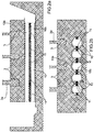
- For a better understanding of the invention, an embodiment will be described by way of non-limitative example only, with the aid of the figures of the accompanying drawing, in which:
-
figures 1a and 1b are two views of a first step of implementation of the seismic insulating structure according to the present invention; -
figures 2a and 2b are two views of a second step of implementation of the seismic insulating structure according to the present invention; -
figures 3a and 3b are two views of a third step of implementation of the seismic insulating structure according to the present invention; -
figures 4a and 4b are two views of the seismic insulating structure according to a preferred embodiment of the present invention; and -
figures 5a and 5b are two views of the seismic insulating structure according to a further preferred embodiment of the present invention. - In
figures 4a and 4b , numeral 1 illustrates as a whole a preferred embodiment of the seismic insulating structure according to the present invention. The structure 1 comprises an insulatingplatform 2 arranged i under thefoundations 3 of thebuilding 3a to which the structure 1 is intended to be applied, and comprising, in turn, atop block 4, abottom block 5 separated from thetop block 4, a plurality ofseismic insulators 6 arranged between thetop block 4 and thebottom block 5. Structure 1 further comprises an innerunderground wall 7 fixed on the bottom to thetop block 4 of the insulatingplatform 2 and arranged so as to contain the ground that surroundsbuilding 3a, and an outerunderground wall 8 fixed on the bottom to thebottom block 5 and arranged about the innerunderground wall 7. The innerunderground wall 7 and the outerunderground wall 8 combinedly define a seismic joint 9 made from a trench in the ground. - In particular, the insulating
platform 2 consists of a plurality oftubes 10 arranged side by side in a horizontal position under thefoundations 3. The tubes are made of concrete and have a cylindrical structure. - Each
tube 10 consists of atop cap 10a and abottom cap 10b separate from one another and between which a plurality ofseismic insulators 6, of known type, is housed. Eachtop cap 10a is rigidly connected to the adjacenttop cap 10a, so as to form thetop block 4, which thus consists of all thetop caps 10a of thetubes 10. - Each
bottom cap 10b is rigidly connected to theadjacent bottom cap 10b, so as to form thebottom block 5, which thus consists of all thebottom caps 10a of thetubes 10. - In particular, the connections between the various
top caps 10a and thevarious bottom caps 10b may be made by means of a casting of reinforced concrete or other material. - Otherwise, the
tubes 10 may be made of material other than concrete, and so are the connections, providing they are capable of fulfilling the proper technical requirements of their function, and may have a shape other than cylindrical, for example a square or rectangular section. Furthermore, thetubes 10 may be stiffened by metallic ribs or temporary pillars arranged on site. - The distance between the
insulating platform 2 and thefoundations 3 must be defined on a case by case basis according to specific needs, as well as the distance between theinner underground wall 7 and the walls of thebuilding 3a. The distance betweeninner underground wall 7 and the outer inner wall 8 (seismic joint 9) depends on the seismic movement determined in design, which can reach several tens of centimeters. Furthermore, a plurality of energy dissipaters may be accommodated between theinner underground wall 7 and theouter underground wall 8. - In
figures 5a and 5b ,numeral 20 shows another embodiment of the seismic insulating structure according to the present invention. The parts of thestructure 20 equal to those of the structure 1 will be indicated with the same numbers and will not be described again.Structure 20 differs from structure 1 in that it comprises arigid connection 21 between theinner underground wall 7 and thebuilding 3a. The rigid connection between theinner underground wall 7 and thebuilding 3a has the purpose of avoiding oscillations between the same. Alternatively or additionally, thefoundations 3 may be connected to the insulating structure by means of appropriate structures (micropiles or other) or ground stiffening/consolidation (injections or other). - An underground volume, which can be used in various manners, or vehicle transit ways may be obtained between the
foundations 3 and theinsulating platform 2. - The size of the tubes guarantees accessibility and consequently possibility of inspecting and replacing the elements, such as the
seismic insulators 6. -
Figures 1a, 1b ,2a, 2b ,3a, 3c show the various steps of implementation of the structure 1 as described below. -
Figures 1a, 1b ,2a, 2b show the insertion by means of the "auger boring" or "guided auger boring" technique of theconcrete tubes 10 having an inner diameter sufficient to allow the installation and subsequent inspection of the insulators. - Insertion is carried out after digging a trench along a side of the concerned area. Choosing the most suitable technique depends on the features of the subsoil. The
tubes 10, arranged side by side or at an appropriate distance for the subsequent insertion of theseismic insulators 6, must be inserted at a depth to be defined on a case by case basis so as to leave the entire structure unchanged and to allow, when needed, to make an effective connection between foundation and thetubes 10 themselves to possibly obtain a basement. Thetubes 10 consist of two caps,top 10a andbottom 10b, connected to one another by means ofremovable elements 11, appropriately anchored to the caps at two springing lines. - Such
removable elements 11 must consist of parts which are easy to separate and remove so as to facilitate both the housing of theseismic insulators 6 and the discontinuity between the two caps themselves, after inserting the seismic insulators themselves 6. -
Figures 3a 3b show the insertion of theseismic insulators 6 and the disconnection between top 10a andbottom 10b caps. - At the positions of the
seismic insulators 6, theremovable elements 11 between thecaps adjacent bottom caps 10b, being careful to arrange the housings for the brackets of the insulators. - Connections of concrete or other material are made between the adjacent
top caps 10a in which the top brackets of theinsulators 6 are embedded after having arranged theseismic insulators 6. - Finally, the
removable elements 11 are removed, creating the discontinuity betweentop caps 10a andbottom caps 10b, which remain connected only by theinsulators 6. -
Figures 4a and 4b show the structure 1 with the inner 7 and outer 8 underground walls. - The inner 7 and outer 8 underground walls are built along the perimeter of the
building 3a, at an appropriate distance therefrom to be evaluated on a case by case basis. Theinner underground wall 7 must be rigidly connected to theupper block 4, constituted by thetop caps 10a, which constitute a "tank" containing the underground part of thebuilding 3a seismically insulated at the base. Theouter underground wall 8 is rigidly connected to thebottom block 5, constituted by thebottom caps 10b. - As inferred from the description above, the structure of the present invention allows to seismically insulate existing buildings, guaranteeing that the structure and architecture of the building are not damaged in any manner, also with regards to possible underground rooms, which are part of the insulated substructure.
- Furthermore, between the
foundations 3 of thebuilding 3a and theupper caps 10a of thetubes 10, an underground volume usable in various manner, or vehicle transit ways, can be obtained, while the dimensions of the tube guarantee possibility of access and consequently of inspecting and maintaining the structure as a whole, with particular reference to theseismic insulators 6. - Finally, the structure of the present invention allows to make large insulated platforms, particularly suitable for structural aggregates of even considerable size.
Claims (9)
- A seismic insulating structure (1) for buildings characterized by comprising an insulating platform (2) arranged under the foundations (3) of a building (3a) and comprising a top block (4), a bottom block (5) separated from the top block (4), a plurality of seismic insulators (6) arranged between the top block (4) and the bottom block (5), an inner underground wall (7) fixed on the bottom to the top block (4) and an outer underground wall (8) fixed on the bottom to the bottom block (5) and arranged about said inner underground wall (7); said inner underground wall (7) and said outer underground wall (8) defining a seismic joint for their entire height (9, characterized in that the inner underground wall (7) is arranged so as to contain the ground that surrounds said building (3a).
- The seismic insulating structure according to claim 1, characterized in that said insulating platform (2) comprises a plurality of tubes (10) arranged side by side in a horizontal position; each of said tubes (10) consisting of a top cap (10a) and a bottom cap (10b) separate from one another and between which a plurality of seismic insulators (6) is housed; each of the top caps (10a) being rigidly connected to the adjacent top caps (10a), so as to form said top block (4) and each of the bottom caps (10b) being rigidly connected to the adjacent bottom caps (10b), so as to form said bottom block (5).
- The seismic insulating structure according to claim 2, characterized in that said tubes (10) are made of concrete and have a cylindrical structure.
- The seismic insulating structure according to claim 3, characterized by comprising concrete connections between the different top caps (10a) and between the different bottom caps (10b).
- The seismic insulating structure according to any of the preceding claims, characterized by comprising a rigid connection (21) between the inner underground wall (7) and said building (3a).
- A process for making a seismic insulating structure; said process being characterized by comprising in a sequence:- a step of introducing a plurality of tubes (10) under the foundations (3) of a building (3a) to be seismically insulated; said tubes (10) being formed by a top portion (10a) and a bottom portion (10b) connected to one another by means of a plurality of removable elements (11);- a first step of connecting the different bottom portions (10b) to form a single bottom block (5);- a step of positioning a plurality of seismic insulators (6) between the top portions (10a) and the bottom portions (10b);- a second step of connecting the different top portions (10a) to form a single top block (4);- a step of removing the removable elements (11);- a step of forming both an inner underground wall (7) arranged to contain the ground that surrounds the building (3a) and rigidly connected to the top block (4), and an outer underground wall (8) arranged externally to said inner wall (7) and rigidly connected to the lower block (5).
- The process according to claim 6, characterized in that said tubes (10) are made of concrete.
- The process according to claim 7, characterized in that said steps of connecting the different bottom portions (10b) and the different top portions (10a) take place by means of concrete.
- The process according to one of claims 6 to 8, characterized in that said step of introducing the plurality of tubes (10) takes place by means of the "auger boring" or "guided auger boring" technique.
Applications Claiming Priority (2)
| Application Number | Priority Date | Filing Date | Title |
|---|---|---|---|
| ITRM2010A000158A IT1399253B1 (en) | 2010-04-02 | 2010-04-02 | SEISMIC INSULATION STRUCTURE FOR EXISTING BUILDINGS |
| PCT/IB2011/000716 WO2011121439A2 (en) | 2010-04-02 | 2011-04-02 | Seismic insulating structure for existing buildings |
Publications (2)
| Publication Number | Publication Date |
|---|---|
| EP2553176A2 EP2553176A2 (en) | 2013-02-06 |
| EP2553176B1 true EP2553176B1 (en) | 2017-08-23 |
Family
ID=43447035
Family Applications (1)
| Application Number | Title | Priority Date | Filing Date |
|---|---|---|---|
| EP11724737.9A Not-in-force EP2553176B1 (en) | 2010-04-02 | 2011-04-02 | Seismic insulating structure for existing buildings |
Country Status (3)
| Country | Link |
|---|---|
| EP (1) | EP2553176B1 (en) |
| IT (1) | IT1399253B1 (en) |
| WO (1) | WO2011121439A2 (en) |
Families Citing this family (4)
| Publication number | Priority date | Publication date | Assignee | Title |
|---|---|---|---|---|
| CN104895120A (en) * | 2014-09-17 | 2015-09-09 | 国家电网公司 | Basic shock isolating system for interconnecting electric equipment |
| IT201800005642A1 (en) * | 2018-05-23 | 2019-11-23 | ANTI-SEISMIC BASE FOR NEW BUILDING STRUCTURES | |
| NL2022323B1 (en) * | 2018-12-28 | 2020-07-23 | Takkenkamp Groep B V | A method for insulating a ground floor of a building |
| CN118187519B (en) * | 2024-05-20 | 2024-07-30 | 蒲正建设集团有限公司 | Steel column foot reinforced structure |
Citations (2)
| Publication number | Priority date | Publication date | Assignee | Title |
|---|---|---|---|---|
| US981884A (en) * | 1909-03-11 | 1911-01-17 | Otto Ruhl | Earthquake-proof building. |
| JP2009074272A (en) * | 2007-09-19 | 2009-04-09 | Takenaka Komuten Co Ltd | Rebuilding method |
Family Cites Families (2)
| Publication number | Priority date | Publication date | Assignee | Title |
|---|---|---|---|---|
| JP3685842B2 (en) * | 1995-06-26 | 2005-08-24 | 三井住友建設株式会社 | How to replace the base isolation and seismic isolation device |
| US7160061B2 (en) * | 2000-12-04 | 2007-01-09 | Battelle Energy Alliance, Llc | Subterranean barriers including at least one weld |
-
2010
- 2010-04-02 IT ITRM2010A000158A patent/IT1399253B1/en active
-
2011
- 2011-04-02 WO PCT/IB2011/000716 patent/WO2011121439A2/en not_active Ceased
- 2011-04-02 EP EP11724737.9A patent/EP2553176B1/en not_active Not-in-force
Patent Citations (2)
| Publication number | Priority date | Publication date | Assignee | Title |
|---|---|---|---|---|
| US981884A (en) * | 1909-03-11 | 1911-01-17 | Otto Ruhl | Earthquake-proof building. |
| JP2009074272A (en) * | 2007-09-19 | 2009-04-09 | Takenaka Komuten Co Ltd | Rebuilding method |
Also Published As
| Publication number | Publication date |
|---|---|
| WO2011121439A2 (en) | 2011-10-06 |
| WO2011121439A3 (en) | 2011-12-29 |
| ITRM20100158A1 (en) | 2011-10-03 |
| EP2553176A2 (en) | 2013-02-06 |
| IT1399253B1 (en) | 2013-04-11 |
Similar Documents
| Publication | Publication Date | Title |
|---|---|---|
| CN103790393B (en) | A kind of construction method of existing building structure integral replacement | |
| CN111058455B (en) | Deep foundation pit support structure and deep foundation pit construction method | |
| KR20130006420A (en) | Method of constructing underground structure to be newly built | |
| CN110397278A (en) | A method for synchronous construction of above-ground buildings and underground structures | |
| WO2011121439A2 (en) | Seismic insulating structure for existing buildings | |
| JP5937488B2 (en) | Temporary support method for foundation | |
| JP5490300B1 (en) | Retaining wall structure and retaining wall construction method | |
| JP5976373B2 (en) | Pile foundation reinforcement structure and reinforcement method | |
| CN207295756U (en) | Coating subgrade strengthening structure | |
| US4232491A (en) | Swimming pool deck | |
| CN111827303B (en) | Backfill-free foundation pit permanent support system and construction method thereof | |
| JP2015036493A (en) | Method for constructing underground storage tank | |
| JP7386095B2 (en) | Underground structure construction method | |
| JP3641227B2 (en) | Construction method of underground structure | |
| CN208309592U (en) | Foundation pit supporting structure | |
| JP5207086B2 (en) | Construction method of underground tank | |
| AU2020100004A4 (en) | A Method Of Constructing A Column, A Subterranean Structure, And A Structure Made From The Method | |
| CN108104506A (en) | It is a kind of to be used for structural demolition and the temporary facility rebuilded and its construction method | |
| JP4999720B2 (en) | How to rebuild a structure | |
| CN108442406B (en) | Semi-reverse construction method foundation pit inner supporting structure and construction method thereof | |
| CN110616738A (en) | Underground space vertical building construction method and structure | |
| JP2006183276A (en) | Vertical shaft structure and its construction method | |
| CN220579971U (en) | Special-shaped pile capable of being used as anti-floating roof | |
| JP6851180B2 (en) | How to rebuild the building | |
| JP4546357B2 (en) | A method to renovate the underfloor part of the projecting frame of an existing structure |
Legal Events
| Date | Code | Title | Description |
|---|---|---|---|
| PUAI | Public reference made under article 153(3) epc to a published international application that has entered the european phase |
Free format text: ORIGINAL CODE: 0009012 |
|
| 17P | Request for examination filed |
Effective date: 20121024 |
|
| AK | Designated contracting states |
Kind code of ref document: A2 Designated state(s): AL AT BE BG CH CY CZ DE DK EE ES FI FR GB GR HR HU IE IS IT LI LT LU LV MC MK MT NL NO PL PT RO RS SE SI SK SM TR |
|
| DAX | Request for extension of the european patent (deleted) | ||
| REG | Reference to a national code |
Ref country code: DE Ref legal event code: R079 Ref document number: 602011040836 Country of ref document: DE Free format text: PREVIOUS MAIN CLASS: E02D0027480000 Ipc: E04H0009020000 |
|
| GRAP | Despatch of communication of intention to grant a patent |
Free format text: ORIGINAL CODE: EPIDOSNIGR1 |
|
| RIC1 | Information provided on ipc code assigned before grant |
Ipc: E02D 27/48 20060101ALI20170220BHEP Ipc: E02D 27/34 20060101ALI20170220BHEP Ipc: E04H 9/02 20060101AFI20170220BHEP Ipc: E02D 31/08 20060101ALI20170220BHEP |
|
| INTG | Intention to grant announced |
Effective date: 20170316 |
|
| GRAS | Grant fee paid |
Free format text: ORIGINAL CODE: EPIDOSNIGR3 |
|
| GRAA | (expected) grant |
Free format text: ORIGINAL CODE: 0009210 |
|
| AK | Designated contracting states |
Kind code of ref document: B1 Designated state(s): AL AT BE BG CH CY CZ DE DK EE ES FI FR GB GR HR HU IE IS IT LI LT LU LV MC MK MT NL NO PL PT RO RS SE SI SK SM TR |
|
| REG | Reference to a national code |
Ref country code: GB Ref legal event code: FG4D |
|
| REG | Reference to a national code |
Ref country code: CH Ref legal event code: EP |
|
| REG | Reference to a national code |
Ref country code: AT Ref legal event code: REF Ref document number: 921525 Country of ref document: AT Kind code of ref document: T Effective date: 20170915 |
|
| REG | Reference to a national code |
Ref country code: IE Ref legal event code: FG4D |
|
| REG | Reference to a national code |
Ref country code: DE Ref legal event code: R096 Ref document number: 602011040836 Country of ref document: DE |
|
| REG | Reference to a national code |
Ref country code: NL Ref legal event code: MP Effective date: 20170823 |
|
| REG | Reference to a national code |
Ref country code: LT Ref legal event code: MG4D |
|
| REG | Reference to a national code |
Ref country code: AT Ref legal event code: MK05 Ref document number: 921525 Country of ref document: AT Kind code of ref document: T Effective date: 20170823 |
|
| RAP2 | Party data changed (patent owner data changed or rights of a patent transferred) |
Owner name: AGENZIA NAZIONALE PER LE NUOVE TECNOLOGIE, L'ENERG |
|
| PG25 | Lapsed in a contracting state [announced via postgrant information from national office to epo] |
Ref country code: LT Free format text: LAPSE BECAUSE OF FAILURE TO SUBMIT A TRANSLATION OF THE DESCRIPTION OR TO PAY THE FEE WITHIN THE PRESCRIBED TIME-LIMIT Effective date: 20170823 Ref country code: SE Free format text: LAPSE BECAUSE OF FAILURE TO SUBMIT A TRANSLATION OF THE DESCRIPTION OR TO PAY THE FEE WITHIN THE PRESCRIBED TIME-LIMIT Effective date: 20170823 Ref country code: NL Free format text: LAPSE BECAUSE OF FAILURE TO SUBMIT A TRANSLATION OF THE DESCRIPTION OR TO PAY THE FEE WITHIN THE PRESCRIBED TIME-LIMIT Effective date: 20170823 Ref country code: AT Free format text: LAPSE BECAUSE OF FAILURE TO SUBMIT A TRANSLATION OF THE DESCRIPTION OR TO PAY THE FEE WITHIN THE PRESCRIBED TIME-LIMIT Effective date: 20170823 Ref country code: HR Free format text: LAPSE BECAUSE OF FAILURE TO SUBMIT A TRANSLATION OF THE DESCRIPTION OR TO PAY THE FEE WITHIN THE PRESCRIBED TIME-LIMIT Effective date: 20170823 Ref country code: NO Free format text: LAPSE BECAUSE OF FAILURE TO SUBMIT A TRANSLATION OF THE DESCRIPTION OR TO PAY THE FEE WITHIN THE PRESCRIBED TIME-LIMIT Effective date: 20171123 Ref country code: FI Free format text: LAPSE BECAUSE OF FAILURE TO SUBMIT A TRANSLATION OF THE DESCRIPTION OR TO PAY THE FEE WITHIN THE PRESCRIBED TIME-LIMIT Effective date: 20170823 |
|
| PG25 | Lapsed in a contracting state [announced via postgrant information from national office to epo] |
Ref country code: ES Free format text: LAPSE BECAUSE OF FAILURE TO SUBMIT A TRANSLATION OF THE DESCRIPTION OR TO PAY THE FEE WITHIN THE PRESCRIBED TIME-LIMIT Effective date: 20170823 Ref country code: IS Free format text: LAPSE BECAUSE OF FAILURE TO SUBMIT A TRANSLATION OF THE DESCRIPTION OR TO PAY THE FEE WITHIN THE PRESCRIBED TIME-LIMIT Effective date: 20171223 Ref country code: LV Free format text: LAPSE BECAUSE OF FAILURE TO SUBMIT A TRANSLATION OF THE DESCRIPTION OR TO PAY THE FEE WITHIN THE PRESCRIBED TIME-LIMIT Effective date: 20170823 Ref country code: RS Free format text: LAPSE BECAUSE OF FAILURE TO SUBMIT A TRANSLATION OF THE DESCRIPTION OR TO PAY THE FEE WITHIN THE PRESCRIBED TIME-LIMIT Effective date: 20170823 Ref country code: PL Free format text: LAPSE BECAUSE OF FAILURE TO SUBMIT A TRANSLATION OF THE DESCRIPTION OR TO PAY THE FEE WITHIN THE PRESCRIBED TIME-LIMIT Effective date: 20170823 Ref country code: BG Free format text: LAPSE BECAUSE OF FAILURE TO SUBMIT A TRANSLATION OF THE DESCRIPTION OR TO PAY THE FEE WITHIN THE PRESCRIBED TIME-LIMIT Effective date: 20171123 |
|
| PG25 | Lapsed in a contracting state [announced via postgrant information from national office to epo] |
Ref country code: CZ Free format text: LAPSE BECAUSE OF FAILURE TO SUBMIT A TRANSLATION OF THE DESCRIPTION OR TO PAY THE FEE WITHIN THE PRESCRIBED TIME-LIMIT Effective date: 20170823 Ref country code: RO Free format text: LAPSE BECAUSE OF FAILURE TO SUBMIT A TRANSLATION OF THE DESCRIPTION OR TO PAY THE FEE WITHIN THE PRESCRIBED TIME-LIMIT Effective date: 20170823 Ref country code: DK Free format text: LAPSE BECAUSE OF FAILURE TO SUBMIT A TRANSLATION OF THE DESCRIPTION OR TO PAY THE FEE WITHIN THE PRESCRIBED TIME-LIMIT Effective date: 20170823 |
|
| REG | Reference to a national code |
Ref country code: DE Ref legal event code: R097 Ref document number: 602011040836 Country of ref document: DE |
|
| PG25 | Lapsed in a contracting state [announced via postgrant information from national office to epo] |
Ref country code: IT Free format text: LAPSE BECAUSE OF FAILURE TO SUBMIT A TRANSLATION OF THE DESCRIPTION OR TO PAY THE FEE WITHIN THE PRESCRIBED TIME-LIMIT Effective date: 20170823 Ref country code: EE Free format text: LAPSE BECAUSE OF FAILURE TO SUBMIT A TRANSLATION OF THE DESCRIPTION OR TO PAY THE FEE WITHIN THE PRESCRIBED TIME-LIMIT Effective date: 20170823 Ref country code: SM Free format text: LAPSE BECAUSE OF FAILURE TO SUBMIT A TRANSLATION OF THE DESCRIPTION OR TO PAY THE FEE WITHIN THE PRESCRIBED TIME-LIMIT Effective date: 20170823 Ref country code: SK Free format text: LAPSE BECAUSE OF FAILURE TO SUBMIT A TRANSLATION OF THE DESCRIPTION OR TO PAY THE FEE WITHIN THE PRESCRIBED TIME-LIMIT Effective date: 20170823 |
|
| PLBE | No opposition filed within time limit |
Free format text: ORIGINAL CODE: 0009261 |
|
| STAA | Information on the status of an ep patent application or granted ep patent |
Free format text: STATUS: NO OPPOSITION FILED WITHIN TIME LIMIT |
|
| REG | Reference to a national code |
Ref country code: GR Ref legal event code: EP Ref document number: 20170403183 Country of ref document: GR Effective date: 20180627 |
|
| 26N | No opposition filed |
Effective date: 20180524 |
|
| PG25 | Lapsed in a contracting state [announced via postgrant information from national office to epo] |
Ref country code: SI Free format text: LAPSE BECAUSE OF FAILURE TO SUBMIT A TRANSLATION OF THE DESCRIPTION OR TO PAY THE FEE WITHIN THE PRESCRIBED TIME-LIMIT Effective date: 20170823 |
|
| REG | Reference to a national code |
Ref country code: DE Ref legal event code: R119 Ref document number: 602011040836 Country of ref document: DE |
|
| PG25 | Lapsed in a contracting state [announced via postgrant information from national office to epo] |
Ref country code: MC Free format text: LAPSE BECAUSE OF FAILURE TO SUBMIT A TRANSLATION OF THE DESCRIPTION OR TO PAY THE FEE WITHIN THE PRESCRIBED TIME-LIMIT Effective date: 20170823 |
|
| REG | Reference to a national code |
Ref country code: CH Ref legal event code: PL |
|
| REG | Reference to a national code |
Ref country code: BE Ref legal event code: MM Effective date: 20180430 |
|
| GBPC | Gb: european patent ceased through non-payment of renewal fee |
Effective date: 20180402 |
|
| REG | Reference to a national code |
Ref country code: IE Ref legal event code: MM4A |
|
| PG25 | Lapsed in a contracting state [announced via postgrant information from national office to epo] |
Ref country code: DE Free format text: LAPSE BECAUSE OF NON-PAYMENT OF DUE FEES Effective date: 20181101 Ref country code: LU Free format text: LAPSE BECAUSE OF NON-PAYMENT OF DUE FEES Effective date: 20180402 |
|
| PG25 | Lapsed in a contracting state [announced via postgrant information from national office to epo] |
Ref country code: CH Free format text: LAPSE BECAUSE OF NON-PAYMENT OF DUE FEES Effective date: 20180430 Ref country code: GB Free format text: LAPSE BECAUSE OF NON-PAYMENT OF DUE FEES Effective date: 20180402 Ref country code: LI Free format text: LAPSE BECAUSE OF NON-PAYMENT OF DUE FEES Effective date: 20180430 Ref country code: BE Free format text: LAPSE BECAUSE OF NON-PAYMENT OF DUE FEES Effective date: 20180430 |
|
| PG25 | Lapsed in a contracting state [announced via postgrant information from national office to epo] |
Ref country code: FR Free format text: LAPSE BECAUSE OF NON-PAYMENT OF DUE FEES Effective date: 20180430 Ref country code: IE Free format text: LAPSE BECAUSE OF NON-PAYMENT OF DUE FEES Effective date: 20180402 |
|
| PG25 | Lapsed in a contracting state [announced via postgrant information from national office to epo] |
Ref country code: MT Free format text: LAPSE BECAUSE OF NON-PAYMENT OF DUE FEES Effective date: 20180402 |
|
| PG25 | Lapsed in a contracting state [announced via postgrant information from national office to epo] |
Ref country code: PT Free format text: LAPSE BECAUSE OF FAILURE TO SUBMIT A TRANSLATION OF THE DESCRIPTION OR TO PAY THE FEE WITHIN THE PRESCRIBED TIME-LIMIT Effective date: 20170823 Ref country code: HU Free format text: LAPSE BECAUSE OF FAILURE TO SUBMIT A TRANSLATION OF THE DESCRIPTION OR TO PAY THE FEE WITHIN THE PRESCRIBED TIME-LIMIT; INVALID AB INITIO Effective date: 20110402 |
|
| PG25 | Lapsed in a contracting state [announced via postgrant information from national office to epo] |
Ref country code: CY Free format text: LAPSE BECAUSE OF FAILURE TO SUBMIT A TRANSLATION OF THE DESCRIPTION OR TO PAY THE FEE WITHIN THE PRESCRIBED TIME-LIMIT Effective date: 20170823 Ref country code: MK Free format text: LAPSE BECAUSE OF NON-PAYMENT OF DUE FEES Effective date: 20170823 |
|
| PGFP | Annual fee paid to national office [announced via postgrant information from national office to epo] |
Ref country code: TR Payment date: 20200320 Year of fee payment: 10 |
|
| PG25 | Lapsed in a contracting state [announced via postgrant information from national office to epo] |
Ref country code: AL Free format text: LAPSE BECAUSE OF FAILURE TO SUBMIT A TRANSLATION OF THE DESCRIPTION OR TO PAY THE FEE WITHIN THE PRESCRIBED TIME-LIMIT Effective date: 20170823 |
|
| PGFP | Annual fee paid to national office [announced via postgrant information from national office to epo] |
Ref country code: GR Payment date: 20200424 Year of fee payment: 10 |
|
| PG25 | Lapsed in a contracting state [announced via postgrant information from national office to epo] |
Ref country code: GR Free format text: LAPSE BECAUSE OF NON-PAYMENT OF DUE FEES Effective date: 20211108 |
|
| PG25 | Lapsed in a contracting state [announced via postgrant information from national office to epo] |
Ref country code: TR Free format text: LAPSE BECAUSE OF NON-PAYMENT OF DUE FEES Effective date: 20210402 |