EP2552836B1 - Verfahren zur überwachung einer wasserbehandlungsanlage für eine kreislauf-befüllungsanlage - Google Patents
Verfahren zur überwachung einer wasserbehandlungsanlage für eine kreislauf-befüllungsanlage Download PDFInfo
- Publication number
- EP2552836B1 EP2552836B1 EP11713730.7A EP11713730A EP2552836B1 EP 2552836 B1 EP2552836 B1 EP 2552836B1 EP 11713730 A EP11713730 A EP 11713730A EP 2552836 B1 EP2552836 B1 EP 2552836B1
- Authority
- EP
- European Patent Office
- Prior art keywords
- water
- water treatment
- instantaneous
- treatment elements
- conductivity
- Prior art date
- Legal status (The legal status is an assumption and is not a legal conclusion. Google has not performed a legal analysis and makes no representation as to the accuracy of the status listed.)
- Active
Links
Images

Classifications
-
- C—CHEMISTRY; METALLURGY
- C02—TREATMENT OF WATER, WASTE WATER, SEWAGE, OR SLUDGE
- C02F—TREATMENT OF WATER, WASTE WATER, SEWAGE, OR SLUDGE
- C02F1/00—Treatment of water, waste water, or sewage
- C02F1/008—Control or steering systems not provided for elsewhere in subclass C02F
-
- C—CHEMISTRY; METALLURGY
- C02—TREATMENT OF WATER, WASTE WATER, SEWAGE, OR SLUDGE
- C02F—TREATMENT OF WATER, WASTE WATER, SEWAGE, OR SLUDGE
- C02F1/00—Treatment of water, waste water, or sewage
- C02F1/42—Treatment of water, waste water, or sewage by ion-exchange
-
- C—CHEMISTRY; METALLURGY
- C02—TREATMENT OF WATER, WASTE WATER, SEWAGE, OR SLUDGE
- C02F—TREATMENT OF WATER, WASTE WATER, SEWAGE, OR SLUDGE
- C02F2209/00—Controlling or monitoring parameters in water treatment
- C02F2209/05—Conductivity or salinity
-
- C—CHEMISTRY; METALLURGY
- C02—TREATMENT OF WATER, WASTE WATER, SEWAGE, OR SLUDGE
- C02F—TREATMENT OF WATER, WASTE WATER, SEWAGE, OR SLUDGE
- C02F2209/00—Controlling or monitoring parameters in water treatment
- C02F2209/40—Liquid flow rate
-
- C—CHEMISTRY; METALLURGY
- C02—TREATMENT OF WATER, WASTE WATER, SEWAGE, OR SLUDGE
- C02F—TREATMENT OF WATER, WASTE WATER, SEWAGE, OR SLUDGE
- C02F2301/00—General aspects of water treatment
- C02F2301/04—Flow arrangements
- C02F2301/043—Treatment of partial or bypass streams
Definitions
- the invention relates to a method for monitoring a water treatment plant for a water cycle filling plant, with which, for example, water in a water cycle, in particular a heating or cooling circuit is filled, wherein the water treatment plant comprises a container with water treatment elements, and wherein the exhaustion state of the water treatment elements with a Measuring unit is monitored.
- water cycle filling systems When filling water circuits with water, for example in a heating system in a building, many manufacturers prescribe the filling with water of a certain quality. This is to reduce the corrosion or the formation of deposits in the water cycle (especially a boiler) can be prevented. Therefore, water cycle filling systems usually have a container with water treatment elements, such as softeners, through which the intended for the filling water is passed.
- water treatment elements such as softeners
- the water treatment elements can only treat a limited amount of water.
- the DE 10 2005 036 356 B4 describes a water treatment plant for a heating system.
- the publication font WO 2010/017792 A1 describes a control unit for a water softening device in which the state of depletion of the ion exchange resin used is determined by measuring the flow and the conductivity in the inlet.
- a method for monitoring a water treatment plant namely a water cycle filling system, wherein the water treatment plant water in a water cycle, in particular a heating or cooling circuit, is filled, wherein the water treatment plant comprises a container with water treatment elements, wherein by the water treatment elements Desalting or partial desalination takes place, wherein the state of exhaustion of the water treatment elements is monitored by a measuring unit, the following parameters being detected during monitoring: an amount of water M flowing through the container, a first instantaneous conductivity L1 of untreated water, a second instantaneous conductivity L2 of treated water or of partially treated water after an intersection, wherein a depletion of the water treatment elements is signaled when one of the amount of water M and one or more, associated the first conductivity L1 detected residual capacity RK of the water treatment elements below a first threshold GW1, and wherein also a depletion of the water treatment elements is signaled when a deviation of the second instantaneous conductivity L2 from a predetermined
- a double protection of the water treatment takes place. It is both the residual capacity of the water treatment elements on the treated amount of water weighted with the raw water quality prevailing at the extraction (quality of untreated water, measured by the first instantaneous conductivity L1), and the quality of the treated or partially treated water (measured by the second , momentary conductivity L2) monitored.
- the invention provides two monitoring criteria, wherein a depletion of the water treatment elements is signaled when at least one criterion is met.
- Exhaustion signaling is typically through an alarm message, such as one or more audible signals, optical signals, electrical signals or radio signals (e.g., message to a mobile phone or to a control room).
- the signaling of exhaustion detected from M and L1 may be done with a different signal than signaling exhaustion determined from L2 and SW.
- the measuring unit or an associated control unit automatically detects the water quality of the water to be treated and its change via L1. This is especially important with changing water quality (e.g., mobile use in different areas or mixed water supply areas). An optimal utilization of the capacity of the water treatment elements can take place, in particular an early or too late exchange or an early or too late regeneration of the water treatment elements can be avoided.
- the first limit value GW1 indicates the minimum treatment reserve (in liters). Most GW1 is chosen in the order of a few ten liters, but can also be zero.
- the second limit value GW2 indicates the maximum permissible deviation of the conductivity L2 of the treated water from a predetermined desired value SW. If the second conductivity L2 deviates significantly from the desired value, this is an indication of a depletion of the water treatment elements or a defect or a malfunction in the water treatment elements or an associated valve system. GW2 may also include different values for different directions of deviation ("up" and "down").
- desalting or partial desalination is effected by the water treatment elements.
- the treatment success can be read directly at the second instantaneous conductivity.
- the measured conductivity decreases accordingly.
- Desalination or partial desalination reduces corrosion and scale formation in the downstream water cycle.
- the second instantaneous conductivity L2 is measured in partially treated water, and that the blend ratio VV of untreated and treated water is readjusted so that the second instantaneous conductivity L2 corresponds to the setpoint SW.
- the residual capacity of the water treatment elements can be optimally utilized, since an increase in the conductivity or hardness of the treated water towards the end of the treatment capacity can be compensated in the short term by admixing a higher proportion of treated water.
- the water treatment plant comprises a blending device, in particular a motor-controlled blending valve.
- a blending device in particular a motor-controlled blending valve.
- Partially softened or partially desalinated water can be provided by means of the blending device, which some boiler manufacturers demand for optimum operating conditions.
- the blending device is in principle controllable manually or automatically by means of the electronic control unit.
- the water treatment plant is designed as a mobile treatment group as a whole. This allows the plant to easily be transported to different application locations.
- the water treatment plant can be easily separated from a first water cycle, especially after use and spent to another water cycle.
- the container is designed with water treatment elements as a disposable cartridge, wherein the disposable cartridge is arranged in a pressure vessel.
- a container is inexpensive, and cartridge replacement is easy.
- the pressure vessel can be reused. There is no time-consuming regeneration in water treatment elements for demineralization (mixed bed) necessary.
- Disposable cartridges can be coded to detect the type of water treatment or a container change and to avoid confusion. Different cartridges can be used alternately, especially in changing place of use and with changing demands on the heating or cooling water.
- Another advantageous embodiment provides that means for interrupting the flow of water through the container are provided when the water treatment elements are exhausted, in particular wherein the means for interrupting comprise a motorized by the control valve stopcock.
- the means for interrupting comprise a motorized by the control valve stopcock.
- the water treatment plant comprises a display on which the current residual capacity RK of the water treatment elements is displayed.
- the display shows how much water can still be treated ("countdown"). Different cartridges (containers with water treatment elements) can be counted down separately.
- countdown As additional indications are possible in particular: already treated amount of water, measured conductivities and if necessary derived water hardnesses of the untreated and treated water, limit values GW1 and GW2, type of current water treatment (softening, desalination, partial desalination).
- the water treatment plant has a backflow preventer.
- the backflow preventer With the backflow preventer the backflow of heating or cooling water into the local water network (such as the drinking water system) can be prevented.
- the backflow preventer is installed at the outlet of the water treatment plant, so that even in the rest of the water treatment plant (in particular the container with the water treatment elements) can not get circulating water.
- an emergency power module is provided for supplying energy to the water treatment system.
- the emergency power module is an operation of the system in case of interruption of the power supply, for example in a change of location possible; stored values are retained (about GW1 and GW2 in the control unit).
- the water treatment plant can also be operated independently of the mains via the emergency power module.
- a valve can be closed with the emergency power module and the water flow can be interrupted.
- the Fig. 1 shows a water treatment plant 1, here a water cycle filling system, connected to a water circuit 4, here a heating circuit of a heating system of a building.
- the water treatment plant and the water cycle form a water cycle filling system.
- untreated water flows (raw water), such as from the local drinking water network to.
- raw water such as from the local drinking water network
- a main stopcock 17 a At the inlet 2 of the water flow can be blocked with a main stopcock 17 a.
- the incoming water is then measured with a first conductivity sensor 5, wherein the measurement result (the first instantaneous conductivity L1) is forwarded to an electronic control unit 11.
- the incoming water is also passed through a flow meter 6, the measurement result (amount of water M) is also passed on to the electronic control unit 11.
- the incoming water passes a closure member, here a by the electronic control unit 11 motor-operated shut-off valve 19, see. Actuator 20.
- the untreated water is then divided into a bypass branch and a water treatment branch.
- the untreated water is passed through water treatment elements 10, which are arranged in an (inner) container 8.
- the container 8 and the water treatment elements 10 are arranged here in a pressure vessel 9. It should be noted that within the scope of the invention it is also possible to provide a plurality of containers connected in parallel and individually selectable, in particular with different types of water treatment elements.
- the bypass branch the untreated water passes through a Verschneideventil 15, which is motorized by the electronic control unit 11, see. Servo motor 16.
- the setting of the blending valve 15 determines the proportions of untreated water and treated water (and thus the blending ratio VV) after the merging of the two branches at the converging point 15a.
- the instantaneous conductivity L2 of the blended water (partially treated water) is measured with a second conductivity sensor 7 and the measurement result forwarded to the electronic control unit 11.
- the blended water is then fed via a backflow preventer 21 and a drain-side main stopcock 17 b to a drain 3.
- This drain 3 is connected to a feed point 4 a of the water cycle 4.
- a circulation pump 23 a plurality of radiators 24, a boiler 22 and a membrane expansion vessel 25 are provided.
- the entirety of the measuring devices 5, 6, 7, which are connected to the control unit 11, can also be referred to as a measuring unit, which is used in the monitoring of the water treatment.
- the control unit 11 determines (as a rule) the remaining capacity RK of the water treatment elements 10. For this purpose, the control unit 11 follows with which amount of water M is treated at the first soft, instantaneous conductivity L1.
- the control unit 11 has a memory 13 in which, in particular, a first limit value GW1 for a minimum treatment reserve is stored.
- the control unit 11 continuously compares whether the (current) residual capacity RK falls below the first limit value GW1. If so, this state is signaled via a signal generator 18.
- a second limit GW2 is still deposited. If the instantaneous, second conductivity L2 of the partially treated water deviates from a setpoint value SW by more than the second limit value GW2, this state is likewise signaled by the signal generator 18.
- the blend ratio VV that is, the proportion of treated water in the blend water
- the second conductivity L2 is half of the first conductivity L1; the setpoint SW is then set accordingly.
- the second conductivity differs greatly (more than the second limit value GW2) from this desired value, then this is an indication of a faulty desalination. For example, if L2 increases sharply, then the water treatment elements 10 are likely to be consumed.
- the desired value SW can also be set absolutely, which is particularly useful when a certain salt content in the waste water is desired.
- the desired mixture ratio VV is usually from the determined raw water quality, ie from the first instantaneous conductivity L1 in untreated water, and derived from the specifications of the user or boiler manufacturer. With the servomotor 16 of the Verschneideventils 15 then a desired blend ratio corresponding adjustment position of the Verschneideventils 15 can be visited.
- L2 can also be kept at the setpoint SW for some time (or for a certain amount of water provided) by increasing the proportion of the treated water at the blended water even when fatigue of the water treatment elements 10 begins. As a result, the residual capacity of the water treatment elements 10 is well utilized.
- the limit values GW1 and GW2 and, if necessary, the desired value SW can be input to the control unit 11 via an input device 14.
- the control unit 11 has a display (display) 12, on which the valid limit values and / or measurement results and / or valve settings and / or setpoint values can be specified.
- the current residual capacity RK can be displayed, which facilitates the planning of filling processes for the user.
- Fig. 1 shown plant can also be used for full treatment of the water at fully closed Verschneideventil 15.
- stopcock 19 can also be the Water flow are automatically interrupted by the control unit 11 in the event of exhaustion.
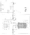
- the Fig. 2 shows a water treatment plant 1 with connected water circuit 4 similar to the in Fig. 1 , so here only the differences should be discussed.
- the water treatment plant 1 of Fig. 2 has only a single conductivity sensor 7, which is arranged on the outlet side. During normal operation of the water treatment plant 1, the second instantaneous conductivity L2 of the partially treated (or fully treated water) can be determined with the conductivity sensor 7.
- valves 27 and 15 are used. Both valves 27, 15 are adjustable via actuators 26, 16 by means of the control unit 11.
- the valve 27 is temporarily closed (and thus the container 8 separated) and the valve 15 (Verschneideventil) open, so that untreated water to the drain 3 - and thus also on the conductivity meter 7 - flows.
- a small amount of untreated water (compared to the total amount of water circulating in circuit 4) does not affect the water cycle 4; but it can also be discarded for the measurement, untreated water discarded.
Landscapes
- Life Sciences & Earth Sciences (AREA)
- Hydrology & Water Resources (AREA)
- Engineering & Computer Science (AREA)
- Environmental & Geological Engineering (AREA)
- Water Supply & Treatment (AREA)
- Chemical & Material Sciences (AREA)
- Organic Chemistry (AREA)
- Separation Using Semi-Permeable Membranes (AREA)
- Treatment Of Water By Ion Exchange (AREA)
- Investigating Or Analyzing Materials By The Use Of Electric Means (AREA)
Priority Applications (1)
| Application Number | Priority Date | Filing Date | Title |
|---|---|---|---|
| PL11713730T PL2552836T3 (pl) | 2010-04-01 | 2011-04-01 | Sposób monitorowania instalacji do uzdatniania wody dla instalacji do napełniania obiegu |
Applications Claiming Priority (2)
| Application Number | Priority Date | Filing Date | Title |
|---|---|---|---|
| DE201010003636 DE102010003636A1 (de) | 2010-04-01 | 2010-04-01 | Verfahren zur Überwachung einer Wasserbehandlungsanlage, insbesondere einer Kreislauf-Befüllungsanlage |
| PCT/EP2011/055092 WO2011121107A1 (de) | 2010-04-01 | 2011-04-01 | Verfahren zur überwachung einer wasserbehandlungsanlage, insbesondere einer kreislauf-befüllungsanlage |
Publications (2)
| Publication Number | Publication Date |
|---|---|
| EP2552836A1 EP2552836A1 (de) | 2013-02-06 |
| EP2552836B1 true EP2552836B1 (de) | 2017-11-15 |
Family
ID=44065142
Family Applications (1)
| Application Number | Title | Priority Date | Filing Date |
|---|---|---|---|
| EP11713730.7A Active EP2552836B1 (de) | 2010-04-01 | 2011-04-01 | Verfahren zur überwachung einer wasserbehandlungsanlage für eine kreislauf-befüllungsanlage |
Country Status (5)
| Country | Link |
|---|---|
| EP (1) | EP2552836B1 (pl) |
| DE (1) | DE102010003636A1 (pl) |
| ES (1) | ES2651091T3 (pl) |
| PL (1) | PL2552836T3 (pl) |
| WO (1) | WO2011121107A1 (pl) |
Cited By (2)
| Publication number | Priority date | Publication date | Assignee | Title |
|---|---|---|---|---|
| WO2023186540A1 (de) * | 2022-03-30 | 2023-10-05 | Grünbeck Wasseraufbereitung GmbH | Wasserbehandlungsanlage und verfahren zum betrieb einer wasserbehandlungsanlage |
| EP4386270A1 (en) * | 2022-12-15 | 2024-06-19 | Intaco Limited | Connector |
Families Citing this family (8)
| Publication number | Priority date | Publication date | Assignee | Title |
|---|---|---|---|---|
| DE102010042541B4 (de) | 2010-10-15 | 2026-03-05 | Brita Se | Vorrichtung zum Behandeln einer Flüssigkeit, insbesondere von Wasser für industrielle und/oder Heimanwendungen |
| DE202014106238U1 (de) * | 2014-12-23 | 2016-03-24 | Gebr. Liebisch Gmbh & Co. Kg | Ionenaustauschereinrichtung |
| DE102015115268A1 (de) | 2015-09-10 | 2015-12-10 | Brita Gmbh | Verfahren und System zum Betreiben einer Vorrichtung zur Behandlung einer wässrigen Flüssigkeit |
| EP3357868B1 (en) * | 2017-02-07 | 2025-03-26 | Bwt Aktiengesellschaft | Water softening device and method to operate a water softening device |
| US11261705B2 (en) | 2018-08-13 | 2022-03-01 | Saudi Arabian Oil Company | Systems and methods for treating fluids in oilfield facilities |
| DE102019212388A1 (de) * | 2019-08-19 | 2021-02-25 | Robert Bosch Gmbh | Verfahren zur Kontrolle einer Ionenreduzierung eines Umlauffluids |
| DE102020201824A1 (de) | 2020-02-13 | 2021-08-19 | Wmf Group Gmbh | Getränkebereiter mit verlängerter lebensdauer der filtereinheit |
| DE102024106700A1 (de) * | 2024-03-08 | 2025-09-11 | UWS Technologie GmbH | Wasserbehandlungsvorrichtung, wasserbehandlungssystem, betriebsverfahren |
Citations (1)
| Publication number | Priority date | Publication date | Assignee | Title |
|---|---|---|---|---|
| WO2010017792A1 (de) * | 2008-08-09 | 2010-02-18 | Judo Wasseraufbereitung Gmbh | Nachrüstbare steuereinheit für eine enthärtungsvorrichtung |
Family Cites Families (5)
| Publication number | Priority date | Publication date | Assignee | Title |
|---|---|---|---|---|
| US7329338B2 (en) * | 2004-10-27 | 2008-02-12 | General Electric Company | Conductivity sensor for an ion exchange water softener |
| DE102005036356C5 (de) | 2005-07-29 | 2015-09-10 | Perma-Trade Wassertechnik Gmbh | Wasserbehandlungseinrichtung für eine Heizanlage |
| DE102007009959A1 (de) * | 2007-03-01 | 2008-09-04 | Klaus Seifert | Verfahren und Vorrichtung zur Beseitigung von Ablagerungen in Heizkreisläufen, Kühlkreisläufen und Wärmetauschern |
| US8758628B2 (en) * | 2007-10-09 | 2014-06-24 | Culligan International Company | Sensor assembly for controlling water softener tanks |
| DE102008045354B3 (de) * | 2008-09-02 | 2010-02-25 | Judo Wasseraufbereitung Gmbh | Aussetzen von Messgrößenauswertungen in einer automatischen Wasserenthärtungsanlage bei Vorliegen von definierten Betriebssituationen |
-
2010
- 2010-04-01 DE DE201010003636 patent/DE102010003636A1/de not_active Withdrawn
-
2011
- 2011-04-01 ES ES11713730.7T patent/ES2651091T3/es active Active
- 2011-04-01 PL PL11713730T patent/PL2552836T3/pl unknown
- 2011-04-01 EP EP11713730.7A patent/EP2552836B1/de active Active
- 2011-04-01 WO PCT/EP2011/055092 patent/WO2011121107A1/de not_active Ceased
Patent Citations (1)
| Publication number | Priority date | Publication date | Assignee | Title |
|---|---|---|---|---|
| WO2010017792A1 (de) * | 2008-08-09 | 2010-02-18 | Judo Wasseraufbereitung Gmbh | Nachrüstbare steuereinheit für eine enthärtungsvorrichtung |
Cited By (2)
| Publication number | Priority date | Publication date | Assignee | Title |
|---|---|---|---|---|
| WO2023186540A1 (de) * | 2022-03-30 | 2023-10-05 | Grünbeck Wasseraufbereitung GmbH | Wasserbehandlungsanlage und verfahren zum betrieb einer wasserbehandlungsanlage |
| EP4386270A1 (en) * | 2022-12-15 | 2024-06-19 | Intaco Limited | Connector |
Also Published As
| Publication number | Publication date |
|---|---|
| PL2552836T3 (pl) | 2018-04-30 |
| ES2651091T3 (es) | 2018-01-24 |
| EP2552836A1 (de) | 2013-02-06 |
| DE102010003636A1 (de) | 2011-10-06 |
| WO2011121107A1 (de) | 2011-10-06 |
Similar Documents
| Publication | Publication Date | Title |
|---|---|---|
| EP2552836B1 (de) | Verfahren zur überwachung einer wasserbehandlungsanlage für eine kreislauf-befüllungsanlage | |
| EP2334431B1 (de) | Aussetzen von messgrössenauswertungen in einer automatischen wasserenthärtungsanlage bei vorliegen von definierten betriebssituationen | |
| EP2323953B1 (de) | Nachrüstbare steuereinheit für eine enthärtungsvorrichtung | |
| EP2481713B1 (de) | Verfahren zum Betrieb einer Wasserenthärtungsanlage und Wasserenthärtungsanlage zur Durchführung des Verfahrens | |
| EP3376118B1 (de) | Heizungsarmatur | |
| EP2512994B1 (de) | Rohwasserhärtebestimmung in einer wasserbehandlungsanlage über die leitfähigkeit des weich- oder verschnittwassers | |
| EP3083503B1 (de) | Verschneidungssteuerung mit rohwasserhärtebestimmung über die leitfähigkeit des weich- und verschnittwassers | |
| EP2161244A1 (de) | Wasseraufbereitungsvorrichtung und -verfahren für ein Passagierflugzeug | |
| DE102015203753B4 (de) | Verfahren zum Betrieb einer Wasserbehandlungsvorrichtung | |
| EP2272802B1 (de) | Verwendung einer Vorrichtung zur Behandlung von Zulaufwasser eines Wasserkreislauf | |
| EP2528868B1 (de) | Verfahren zum betrieb einer wasserbehandlungsanlage mit korrektur von kalibrierkennlinien | |
| EP2504284B1 (de) | Steuerung einer verschneideeinrichtung bei regeneration eines teils der harzbehälter einer wasserenthärtungsvorrichtung | |
| EP2836465B1 (de) | Verfahren zum betrieb einer wasserbehandlungsanlage | |
| WO2004054691A1 (de) | Umkehrosmoseanlage | |
| CH707722B1 (de) | Verfahren und Vorrichtung zum Einstellen des pH-Wertes des Heizungswassers einer Heizungsanlage. | |
| EP2836468B1 (de) | Verfahren zum betrieb einer wasserenthärtungsanlage mit verschiedenen betriebsmodi zur regenerationssteuerung | |
| EP4466173B1 (de) | Fahrzeug mit brennstoffzellensystem und aufbereitungsvorrichtung zur aufbereitung des prozesswassers | |
| EP4582390A1 (de) | Steuereinrichtung sowie verfahren zur steuerung einer trinkwasserbehandlungsanlage | |
| DE202022101702U1 (de) | Wasserbehandlungsanlage und Verwendung einer Wasserbehandlungsanlage | |
| DE102022107578A1 (de) | Wasserbehandlungsanlage und Verfahren zum Betrieb einer Wasserbehandlungsanlage |
Legal Events
| Date | Code | Title | Description |
|---|---|---|---|
| PUAI | Public reference made under article 153(3) epc to a published international application that has entered the european phase |
Free format text: ORIGINAL CODE: 0009012 |
|
| 17P | Request for examination filed |
Effective date: 20121102 |
|
| AK | Designated contracting states |
Kind code of ref document: A1 Designated state(s): AL AT BE BG CH CY CZ DE DK EE ES FI FR GB GR HR HU IE IS IT LI LT LU LV MC MK MT NL NO PL PT RO RS SE SI SK SM TR |
|
| RIN1 | Information on inventor provided before grant (corrected) |
Inventor name: STARK, MARKUS Inventor name: SOECKNICK, RALF |
|
| DAX | Request for extension of the european patent (deleted) | ||
| 17Q | First examination report despatched |
Effective date: 20161208 |
|
| GRAP | Despatch of communication of intention to grant a patent |
Free format text: ORIGINAL CODE: EPIDOSNIGR1 |
|
| INTG | Intention to grant announced |
Effective date: 20170606 |
|
| GRAS | Grant fee paid |
Free format text: ORIGINAL CODE: EPIDOSNIGR3 |
|
| GRAA | (expected) grant |
Free format text: ORIGINAL CODE: 0009210 |
|
| AK | Designated contracting states |
Kind code of ref document: B1 Designated state(s): AL AT BE BG CH CY CZ DE DK EE ES FI FR GB GR HR HU IE IS IT LI LT LU LV MC MK MT NL NO PL PT RO RS SE SI SK SM TR |
|
| REG | Reference to a national code |
Ref country code: CH Ref legal event code: EP Ref country code: GB Ref legal event code: FG4D Free format text: NOT ENGLISH Ref country code: CH Ref legal event code: NV Representative=s name: RIEDERER HASLER AND PARTNER PATENTANWAELTE AG, CH Ref country code: AT Ref legal event code: REF Ref document number: 946067 Country of ref document: AT Kind code of ref document: T Effective date: 20171115 |
|
| REG | Reference to a national code |
Ref country code: IE Ref legal event code: FG4D Free format text: LANGUAGE OF EP DOCUMENT: GERMAN |
|
| REG | Reference to a national code |
Ref country code: DE Ref legal event code: R096 Ref document number: 502011013292 Country of ref document: DE |
|
| REG | Reference to a national code |
Ref country code: ES Ref legal event code: FG2A Ref document number: 2651091 Country of ref document: ES Kind code of ref document: T3 Effective date: 20180124 |
|
| REG | Reference to a national code |
Ref country code: NL Ref legal event code: FP |
|
| REG | Reference to a national code |
Ref country code: LT Ref legal event code: MG4D |
|
| REG | Reference to a national code |
Ref country code: FR Ref legal event code: PLFP Year of fee payment: 8 |
|
| PG25 | Lapsed in a contracting state [announced via postgrant information from national office to epo] |
Ref country code: NO Free format text: LAPSE BECAUSE OF FAILURE TO SUBMIT A TRANSLATION OF THE DESCRIPTION OR TO PAY THE FEE WITHIN THE PRESCRIBED TIME-LIMIT Effective date: 20180215 Ref country code: LT Free format text: LAPSE BECAUSE OF FAILURE TO SUBMIT A TRANSLATION OF THE DESCRIPTION OR TO PAY THE FEE WITHIN THE PRESCRIBED TIME-LIMIT Effective date: 20171115 Ref country code: FI Free format text: LAPSE BECAUSE OF FAILURE TO SUBMIT A TRANSLATION OF THE DESCRIPTION OR TO PAY THE FEE WITHIN THE PRESCRIBED TIME-LIMIT Effective date: 20171115 Ref country code: SE Free format text: LAPSE BECAUSE OF FAILURE TO SUBMIT A TRANSLATION OF THE DESCRIPTION OR TO PAY THE FEE WITHIN THE PRESCRIBED TIME-LIMIT Effective date: 20171115 |
|
| PG25 | Lapsed in a contracting state [announced via postgrant information from national office to epo] |
Ref country code: LV Free format text: LAPSE BECAUSE OF FAILURE TO SUBMIT A TRANSLATION OF THE DESCRIPTION OR TO PAY THE FEE WITHIN THE PRESCRIBED TIME-LIMIT Effective date: 20171115 Ref country code: BG Free format text: LAPSE BECAUSE OF FAILURE TO SUBMIT A TRANSLATION OF THE DESCRIPTION OR TO PAY THE FEE WITHIN THE PRESCRIBED TIME-LIMIT Effective date: 20180215 Ref country code: RS Free format text: LAPSE BECAUSE OF FAILURE TO SUBMIT A TRANSLATION OF THE DESCRIPTION OR TO PAY THE FEE WITHIN THE PRESCRIBED TIME-LIMIT Effective date: 20171115 Ref country code: GR Free format text: LAPSE BECAUSE OF FAILURE TO SUBMIT A TRANSLATION OF THE DESCRIPTION OR TO PAY THE FEE WITHIN THE PRESCRIBED TIME-LIMIT Effective date: 20180216 Ref country code: HR Free format text: LAPSE BECAUSE OF FAILURE TO SUBMIT A TRANSLATION OF THE DESCRIPTION OR TO PAY THE FEE WITHIN THE PRESCRIBED TIME-LIMIT Effective date: 20171115 |
|
| PG25 | Lapsed in a contracting state [announced via postgrant information from national office to epo] |
Ref country code: SK Free format text: LAPSE BECAUSE OF FAILURE TO SUBMIT A TRANSLATION OF THE DESCRIPTION OR TO PAY THE FEE WITHIN THE PRESCRIBED TIME-LIMIT Effective date: 20171115 Ref country code: CZ Free format text: LAPSE BECAUSE OF FAILURE TO SUBMIT A TRANSLATION OF THE DESCRIPTION OR TO PAY THE FEE WITHIN THE PRESCRIBED TIME-LIMIT Effective date: 20171115 Ref country code: CY Free format text: LAPSE BECAUSE OF FAILURE TO SUBMIT A TRANSLATION OF THE DESCRIPTION OR TO PAY THE FEE WITHIN THE PRESCRIBED TIME-LIMIT Effective date: 20171115 Ref country code: DK Free format text: LAPSE BECAUSE OF FAILURE TO SUBMIT A TRANSLATION OF THE DESCRIPTION OR TO PAY THE FEE WITHIN THE PRESCRIBED TIME-LIMIT Effective date: 20171115 Ref country code: EE Free format text: LAPSE BECAUSE OF FAILURE TO SUBMIT A TRANSLATION OF THE DESCRIPTION OR TO PAY THE FEE WITHIN THE PRESCRIBED TIME-LIMIT Effective date: 20171115 |
|
| REG | Reference to a national code |
Ref country code: DE Ref legal event code: R097 Ref document number: 502011013292 Country of ref document: DE |
|
| PG25 | Lapsed in a contracting state [announced via postgrant information from national office to epo] |
Ref country code: RO Free format text: LAPSE BECAUSE OF FAILURE TO SUBMIT A TRANSLATION OF THE DESCRIPTION OR TO PAY THE FEE WITHIN THE PRESCRIBED TIME-LIMIT Effective date: 20171115 Ref country code: SM Free format text: LAPSE BECAUSE OF FAILURE TO SUBMIT A TRANSLATION OF THE DESCRIPTION OR TO PAY THE FEE WITHIN THE PRESCRIBED TIME-LIMIT Effective date: 20171115 |
|
| PLBE | No opposition filed within time limit |
Free format text: ORIGINAL CODE: 0009261 |
|
| STAA | Information on the status of an ep patent application or granted ep patent |
Free format text: STATUS: NO OPPOSITION FILED WITHIN TIME LIMIT |
|
| PG25 | Lapsed in a contracting state [announced via postgrant information from national office to epo] |
Ref country code: MT Free format text: LAPSE BECAUSE OF FAILURE TO SUBMIT A TRANSLATION OF THE DESCRIPTION OR TO PAY THE FEE WITHIN THE PRESCRIBED TIME-LIMIT Effective date: 20171115 |
|
| 26N | No opposition filed |
Effective date: 20180817 |
|
| PG25 | Lapsed in a contracting state [announced via postgrant information from national office to epo] |
Ref country code: SI Free format text: LAPSE BECAUSE OF FAILURE TO SUBMIT A TRANSLATION OF THE DESCRIPTION OR TO PAY THE FEE WITHIN THE PRESCRIBED TIME-LIMIT Effective date: 20171115 Ref country code: MC Free format text: LAPSE BECAUSE OF FAILURE TO SUBMIT A TRANSLATION OF THE DESCRIPTION OR TO PAY THE FEE WITHIN THE PRESCRIBED TIME-LIMIT Effective date: 20171115 |
|
| REG | Reference to a national code |
Ref country code: IE Ref legal event code: MM4A |
|
| PG25 | Lapsed in a contracting state [announced via postgrant information from national office to epo] |
Ref country code: IE Free format text: LAPSE BECAUSE OF NON-PAYMENT OF DUE FEES Effective date: 20180401 |
|
| PG25 | Lapsed in a contracting state [announced via postgrant information from national office to epo] |
Ref country code: TR Free format text: LAPSE BECAUSE OF FAILURE TO SUBMIT A TRANSLATION OF THE DESCRIPTION OR TO PAY THE FEE WITHIN THE PRESCRIBED TIME-LIMIT Effective date: 20171115 |
|
| PG25 | Lapsed in a contracting state [announced via postgrant information from national office to epo] |
Ref country code: PT Free format text: LAPSE BECAUSE OF FAILURE TO SUBMIT A TRANSLATION OF THE DESCRIPTION OR TO PAY THE FEE WITHIN THE PRESCRIBED TIME-LIMIT Effective date: 20171115 Ref country code: HU Free format text: LAPSE BECAUSE OF FAILURE TO SUBMIT A TRANSLATION OF THE DESCRIPTION OR TO PAY THE FEE WITHIN THE PRESCRIBED TIME-LIMIT; INVALID AB INITIO Effective date: 20110401 |
|
| PG25 | Lapsed in a contracting state [announced via postgrant information from national office to epo] |
Ref country code: MK Free format text: LAPSE BECAUSE OF NON-PAYMENT OF DUE FEES Effective date: 20171115 |
|
| PG25 | Lapsed in a contracting state [announced via postgrant information from national office to epo] |
Ref country code: AL Free format text: LAPSE BECAUSE OF FAILURE TO SUBMIT A TRANSLATION OF THE DESCRIPTION OR TO PAY THE FEE WITHIN THE PRESCRIBED TIME-LIMIT Effective date: 20171115 Ref country code: IS Free format text: LAPSE BECAUSE OF FAILURE TO SUBMIT A TRANSLATION OF THE DESCRIPTION OR TO PAY THE FEE WITHIN THE PRESCRIBED TIME-LIMIT Effective date: 20180315 |
|
| PGFP | Annual fee paid to national office [announced via postgrant information from national office to epo] |
Ref country code: PL Payment date: 20250130 Year of fee payment: 15 |
|
| PGFP | Annual fee paid to national office [announced via postgrant information from national office to epo] |
Ref country code: NL Payment date: 20250422 Year of fee payment: 15 |
|
| PGFP | Annual fee paid to national office [announced via postgrant information from national office to epo] |
Ref country code: LU Payment date: 20250417 Year of fee payment: 15 |
|
| PGFP | Annual fee paid to national office [announced via postgrant information from national office to epo] |
Ref country code: DE Payment date: 20250424 Year of fee payment: 15 |
|
| PGFP | Annual fee paid to national office [announced via postgrant information from national office to epo] |
Ref country code: GB Payment date: 20250423 Year of fee payment: 15 Ref country code: ES Payment date: 20250519 Year of fee payment: 15 |
|
| PGFP | Annual fee paid to national office [announced via postgrant information from national office to epo] |
Ref country code: BE Payment date: 20250422 Year of fee payment: 15 Ref country code: IT Payment date: 20250430 Year of fee payment: 15 |
|
| PGFP | Annual fee paid to national office [announced via postgrant information from national office to epo] |
Ref country code: FR Payment date: 20250422 Year of fee payment: 15 |
|
| PGFP | Annual fee paid to national office [announced via postgrant information from national office to epo] |
Ref country code: CH Payment date: 20250501 Year of fee payment: 15 |
|
| PGFP | Annual fee paid to national office [announced via postgrant information from national office to epo] |
Ref country code: AT Payment date: 20250416 Year of fee payment: 15 |