EP2552782B1 - Method of commanding an attitude control system and attitude control system of a space vehicle - Google Patents
Method of commanding an attitude control system and attitude control system of a space vehicle Download PDFInfo
- Publication number
- EP2552782B1 EP2552782B1 EP11710219.4A EP11710219A EP2552782B1 EP 2552782 B1 EP2552782 B1 EP 2552782B1 EP 11710219 A EP11710219 A EP 11710219A EP 2552782 B1 EP2552782 B1 EP 2552782B1
- Authority
- EP
- European Patent Office
- Prior art keywords
- attitude
- during
- subsystem
- reaction
- sub
- Prior art date
- Legal status (The legal status is an assumption and is not a legal conclusion. Google has not performed a legal analysis and makes no representation as to the accuracy of the status listed.)
- Active
Links
- 238000000034 method Methods 0.000 title claims description 25
- 238000002360 preparation method Methods 0.000 claims description 41
- 239000013598 vector Substances 0.000 claims description 15
- 230000006641 stabilisation Effects 0.000 description 10
- 238000011105 stabilization Methods 0.000 description 9
- 230000001133 acceleration Effects 0.000 description 7
- 230000000694 effects Effects 0.000 description 6
- 238000005259 measurement Methods 0.000 description 5
- 230000008094 contradictory effect Effects 0.000 description 2
- 230000007423 decrease Effects 0.000 description 2
- 230000006870 function Effects 0.000 description 2
- 230000003287 optical effect Effects 0.000 description 2
- 230000008569 process Effects 0.000 description 2
- 239000000126 substance Substances 0.000 description 2
- 241000287107 Passer Species 0.000 description 1
- 230000004913 activation Effects 0.000 description 1
- 230000002411 adverse Effects 0.000 description 1
- 230000008901 benefit Effects 0.000 description 1
- 238000004891 communication Methods 0.000 description 1
- 238000004590 computer program Methods 0.000 description 1
- 230000001186 cumulative effect Effects 0.000 description 1
- 230000006866 deterioration Effects 0.000 description 1
- 238000010586 diagram Methods 0.000 description 1
- 238000005516 engineering process Methods 0.000 description 1
- 239000012530 fluid Substances 0.000 description 1
- 238000010438 heat treatment Methods 0.000 description 1
- 230000006698 induction Effects 0.000 description 1
- 238000005461 lubrication Methods 0.000 description 1
- 230000003071 parasitic effect Effects 0.000 description 1
- 230000005855 radiation Effects 0.000 description 1
- 230000000087 stabilizing effect Effects 0.000 description 1
- 230000007704 transition Effects 0.000 description 1
- 230000001960 triggered effect Effects 0.000 description 1
- 238000004804 winding Methods 0.000 description 1
Images


Classifications
-
- B—PERFORMING OPERATIONS; TRANSPORTING
- B64—AIRCRAFT; AVIATION; COSMONAUTICS
- B64G—COSMONAUTICS; VEHICLES OR EQUIPMENT THEREFOR
- B64G1/00—Cosmonautic vehicles
- B64G1/22—Parts of, or equipment specially adapted for fitting in or to, cosmonautic vehicles
- B64G1/24—Guiding or controlling apparatus, e.g. for attitude control
- B64G1/28—Guiding or controlling apparatus, e.g. for attitude control using inertia or gyro effect
- B64G1/283—Guiding or controlling apparatus, e.g. for attitude control using inertia or gyro effect using reaction wheels
-
- B—PERFORMING OPERATIONS; TRANSPORTING
- B64—AIRCRAFT; AVIATION; COSMONAUTICS
- B64G—COSMONAUTICS; VEHICLES OR EQUIPMENT THEREFOR
- B64G1/00—Cosmonautic vehicles
- B64G1/10—Artificial satellites; Systems of such satellites; Interplanetary vehicles
- B64G1/1021—Earth observation satellites
Definitions
- the method comprises, during the observation phase, a stop holding step of the at least one reaction wheel, during which the speed of rotation of each reaction wheel is maintained at a substantially zero value.
- the invention finds a particularly advantageous, although in no way limiting, application in the case of the attitude control of a satellite performing an observation mission of a celestial body, for example an Earth observation mission.
- control device 350 sends one or more control commands to the maneuvering subsystem 300 which have the effect of setting the speed of rotation of the wheels of the reaction wheel. reaction at a substantially zero value, prior to an observation phase and after the preparation step 50.
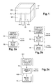
- the figure 2b represents a particular mode of implementation, in which, during the observation phases, the method comprises a step 60 maintaining the stopping of the reaction wheels.
- any request for total kinetic moment can be distributed on said four reaction wheels with a degree of freedom.
- the figure 4 schematically represents the elementary kinetic moments of two reaction wheels of the maneuvering subsystem 300.
- two reaction wheels R 1 and R 2 which have substantially the same axis of rotation.
- the elementary kinetic moment of the reaction wheel R 1 is controlled to switch the satellite 10.
Description
La présente invention appartient au domaine du contrôle d'attitude de véhicules spatiaux. Plus particulièrement, la présente invention concerne le contrôle d'attitude de véhicules spatiaux effectuant une mission d'observation et dont l'attitude est modifiée au cours de phases de préparation, suivies de phases d'observation, au cours desquelles des prises de vues sont effectuées.The present invention belongs to the field of attitude control of space vehicles. More particularly, the present invention relates to the attitude control of space vehicles performing an observation mission and whose attitude is modified during preparation phases, followed by observation phases, during which shots are taken. performed.
Dans le cas notamment de missions d'observation de la Terre à très haute résolution par satellite depuis une orbite basse (dite « orbite LEO »), d'altitude inférieure à quelques milliers de kilomètres, ou depuis une orbite haute (allant jusqu'à l'orbite géostationnaire, dite « orbite GEO »), il est nécessaire d'avoir une stabilité très importante de la ligne de visée des instruments d'observation mis en oeuvre.In the case in particular of very high-resolution satellite Earth observation missions from a low orbit (called "LEO orbit"), of altitude less than a few thousand kilometers, or from a high orbit (up to the geostationary orbit, called "GEO orbit"), it is necessary to have a very important stability of the line of sight of the observation instruments used.
Un satellite d'observation est généralement muni d'un système de contrôle d'attitude, comportant un ou des actionneurs inertiels, pour aligner la ligne de visée d'un instrument d'observation du satellite sur une direction souhaitée, et stabiliser l'attitude de cet instrument d'observation pendant la prise de vue.An observation satellite is generally provided with an attitude control system, including one or more inertial actuators, to align the line of sight of a satellite observation instrument with a desired direction, and to stabilize the attitude. of this observation instrument during the shooting.
Dans le cas d'actionneurs inertiels de type roues de réaction, il est connu que la rotation des balourds des roues de réaction crée des vibrations qui se propagent jusqu'à la ligne de visée de l'instrument d'observation et altèrent la qualité des images. Les vibrations sont d'autant plus importantes que les roues de réaction utilisées sont de forte capacité en couple et en moment cinétique, et donc que la masse et la vitesse du rotor sont importantes.In the case of inertial actuators of the reaction wheel type, it is known that the rotation of the unbalances of the reaction wheels creates vibrations which propagate up to the line of sight of the observation instrument and adversely affect the quality of the reaction wheels. images. The vibrations are all the more important that the reaction wheels used are of high torque and kinetic moment capacity, and therefore that the mass and speed of the rotor are important.
Cela conduit à des exigences contradictoires dans le cas de satellites devant réaliser des manoeuvres de basculement rapides et fréquentes pour multiplier les prises de vue. En effet, pour effectuer des manoeuvres rapides, il faudra utiliser des roues de réaction de forte capacité, qui produiront de fortes vibrations lors des prises de vue.This leads to contradictory requirements in the case of satellites having to perform fast and frequent switching maneuvers to multiply the shots. Indeed, to perform quick maneuvers, it will use high capacity reaction wheels, which will produce strong vibrations when shooting.
Afin de limiter les vibrations engendrées par des roues de réaction, il est connu, notamment de la demande internationale
Il est connu également du brevet
La présente invention a pour objectif de fournir un système de contrôle de l'attitude d'un véhicule spatial, par exemple un satellite d'observation de la Terre, ainsi qu'un procédé de commande d'un tel système, qui permettent à la fois de modifier rapidement l'attitude du véhicule spatial lors des phases de préparation, et de limiter les vibrations lors des phases d'observation.The object of the present invention is to provide a system for controlling the attitude of a spacecraft, for example an Earth observation satellite, as well as a method of controlling such a system, which enables the time to quickly modify the attitude of the spacecraft during the preparation phases, and to limit the vibrations during the observation phases.
La présente invention concerne un procédé de commande d'un système de contrôle d'attitude d'un véhicule spatial, le système de contrôle d'attitude comportant un sous-système de manoeuvre comprenant au moins une roue de réaction, et l'attitude du véhicule spatial devant être contrôlée au cours d'au moins une phase de préparation suivie d'une phase d'observation au cours de laquelle une prise de vue doit être effectuée. Selon l'invention, le procédé comporte, au cours de l'au moins une phase de préparation :
- une étape de préparation, au cours de laquelle le sous-système de manoeuvre est commandé pour contrôler l'attitude du véhicule spatial,
- suivie d'une étape de mise à l'arrêt de l'au moins une roue de réaction, au cours de laquelle la vitesse de rotation de l'au moins une roue de réaction est mise à une valeur sensiblement nulle préalablement à ladite phase d'observation.
- a preparation step, during which the maneuvering subsystem is controlled to control the attitude of the spacecraft,
- followed by a step of stopping the at least one reaction wheel, during which the speed of rotation of the at least one reaction wheel is set to a substantially zero value prior to said observation phase.
De préférence, dans un système de contrôle d'attitude comportant un sous-système de contrôle fin, de signature vibratoire inférieure à celle du sous-système de manoeuvre, le sous-système de contrôle fin est commandé, au cours de la phase d'observation, pour contrôler l'attitude du véhicule spatial.Preferably, in an attitude control system comprising a fine control subsystem, with a vibration signature lower than that of the maneuvering subsystem, the fine control subsystem is controlled, during the phase of control. observation, to control the attitude of the space vehicle.
De préférence, l'étape de mise à l'arrêt de l'au moins une roue de réaction comporte une sous-étape de décélération de l'au moins une roue de réaction en boucle fermée ou de freinage de ladite roue en boucle ouverte.Preferably, the step of stopping the at least one reaction wheel comprises a sub-step of decelerating the at least one closed-loop reaction wheel or braking of said open-loop wheel.
De préférence, dans un sous-système de manoeuvre dont l'au moins une roue de réaction est entrainée en rotation par un moteur électrique polyphasé, la sous-étape de freinage en boucle ouverte consiste à court-circuiter les phases dudit moteur électrique polyphasé. De préférence, la sous-étape de freinage en boucle ouverte est exécutée lorsque la vitesse de rotation de l'au moins une roue est inférieure à un seuil prédéfini.Preferably, in a maneuvering sub-system of which the at least one reaction wheel is rotated by a polyphase electric motor, the open-loop braking sub-step consists of short-circuiting the phases of said polyphase electric motor. Preferably, the open loop braking sub-step is executed when the speed of rotation of the at least one wheel is less than a predefined threshold.
De préférence, l'étape de préparation comporte une sous-étape de manoeuvre, au cours de laquelle le sous-système de manoeuvre est commandé pour basculer l'attitude du véhicule spatial d'une attitude d'observation à une autre, et une sous-étape au cours de laquelle le sous-système de manoeuvre est commandé pour stabiliser l'attitude du véhicule spatial autour d'une attitude d'observation.Preferably, the preparation step comprises a maneuver sub-step, during which the maneuvering subsystem is controlled to switch the attitude of the space vehicle from one observation attitude to another, and a sub-step of a step in which the maneuvering subsystem is controlled to stabilize the attitude of the spacecraft around an attitude of observation.
De préférence, l'étape de préparation comporte une sous-étape de dé-saturation du sous-système de manoeuvre, au cours de laquelle on compense en tout ou partie des moments cinétiques induits par des couples perturbateurs externes.Preferably, the preparation step comprises a sub-step of de-saturation of the maneuvering subsystem, during which all or part of the kinetic moments induced by external interference couples are compensated.
De préférence, la dé-saturation est effectuée en commandant le sous-système de contrôle fin, et/ou en commandant un sous-système de dé-saturation du système de contrôle d'attitude.Preferably, the unsaturation is performed by controlling the fine control subsystem, and / or by controlling a subsystem subsystem of the attitude control system.
De préférence, dans un sous-système de manoeuvre comportant une pluralité de roues de réaction configurées de sorte qu'il existe au moins un vecteur de vitesses de rotation non toutes nulles, dit « noyau du sous-système de manoeuvre », pour lequel la somme des moments cinétiques élémentaires générés par chacune desdites roues de réaction est sensiblement nulle, l'étape de préparation comporte, au début de l'au moins une phase de préparation, une sous-étape d'accélération des roues de réaction autour du noyau du sous-système de manoeuvre. De préférence, l'étape de préparation comporte en outre une sous-étape de décélération des roues de réaction autour du noyau du sous-système de manoeuvre, préalable à l'étape de mise à l'arrêt des roues de réaction.Preferably, in an operating subsystem comprising a plurality of reaction wheels configured so that there is at least one vector of rotational speeds that are not all zero, called "core of the maneuvering subsystem", for which the sum of the elementary kinetic moments generated by each of said reaction wheels is substantially zero, the preparation step comprises, at the beginning of the at least one preparation phase, a substep of acceleration of the reaction wheels around the nucleus of the reaction wheel. subsystem maneuvering. Preferably, the preparation step further comprises a substep of deceleration of the reaction wheels around the core of the maneuvering subsystem, prior to the step of stopping the reaction wheels.
De préférence, le procédé comporte, au cours de la phase d'observation, une étape de maintien à l'arrêt de l'au moins une roue de réaction, au cours de laquelle la vitesse de rotation de chaque roue de réaction est maintenue à une valeur sensiblement nulle.Preferably, the method comprises, during the observation phase, a stop holding step of the at least one reaction wheel, during which the speed of rotation of each reaction wheel is maintained at a substantially zero value.
La présente invention concerne également un système de contrôle d'attitude d'un véhicule spatial, comportant un sous-système de manoeuvre comprenant au moins une roue de réaction, mis en oeuvre pour contrôler l'attitude du véhicule spatial au cours d'au moins une phase de préparation, laquelle au moins une phase de préparation est suivie d'une phase d'observation au cours de laquelle une prise de vue doit être effectuée. Selon l'invention, le système de contrôle d'attitude comporte des moyens adaptés à effectuer une mise à l'arrêt de l'au moins une roue de réaction préalablement à ladite phase d'observation.The present invention also relates to an attitude control system of a spacecraft, comprising an operating subsystem comprising at least one reaction wheel, implemented to control the attitude of the spacecraft during at least a preparation phase, which at least one preparation phase is followed by an observation phase during which a shot must be taken. According to the invention, the attitude control system comprises means adapted to perform a stopping of the at least one reaction wheel prior to said observation phase.
De préférence, le système de contrôle d'attitude comporte un sous-système de contrôle fin, de signature vibratoire inférieure à celle du sous-système de manoeuvre, mis en oeuvre pour contrôler l'attitude du véhicule spatial au cours de la phase d'observation.Preferably, the attitude control system comprises a fine control subsystem with a vibration signature lower than that of the maneuvering subsystem, used to control the attitude of the spacecraft during the phase of control. observation.
De préférence, le système de contrôle d'attitude comporte un sous-système de dé-saturation, adapté à compenser en tout ou partie des moments cinétiques élémentaires induits par des couples perturbateurs externes.Preferably, the attitude control system comprises a de-saturation subsystem, adapted to compensate in all or part of the elementary kinetic moments induced by external interference couples.
L'invention sera mieux comprise à la lecture de la description suivante, donnée à titre d'exemple nullement limitatif, et faite en se référant aux figures qui représentent :
-
Figure 1 : une représentation schématique d'un satellite comportant un système de contrôle d'attitude selon l'invention, -
Figures 2a, 2b, 2c ,2d et 2e : des diagrammes illustrant certaines étapes d'un procédé de commande d'un système de contrôle d'attitude, selon différents modes de mise en oeuvre, -
Figure 3a et 3b : des exemples illustrant, dans le temps, la vitesse de rotation d'une roue de réaction au cours d'une étape de mise à l'arrêt selon l'invention, -
Figure 4 : un exemple illustrant, dans le temps, le contrôle de roues de réaction d'un sous-système de manoeuvre selon l'invention.
-
Figure 1 : a schematic representation of a satellite comprising an attitude control system according to the invention, -
Figures 2a, 2b, 2c ,2d and 2nd : diagrams illustrating certain steps of a control method of an attitude control system, according to different modes of implementation, -
Figure 3a and 3b : examples illustrating, in time, the speed of rotating a reaction wheel during a stopping step according to the invention, -
Figure 4 : an example illustrating, in time, the control of reaction wheels of a maneuvering subsystem according to the invention.
L'invention trouve une application particulièrement avantageuse, bien que nullement limitative, dans le cas du contrôle d'attitude d'un satellite effectuant une mission d'observation d'un corps céleste, par exemple une mission d'observation de la Terre.The invention finds a particularly advantageous, although in no way limiting, application in the case of the attitude control of a satellite performing an observation mission of a celestial body, for example an Earth observation mission.
Un tel satellite d'observation est destiné à être placé sur une orbite Terrestre, par exemple une orbite basse (dite « orbite LEO »), une orbite moyenne (dite « orbite MEO ») ou, de préférence, une orbite haute telle que l'orbite géostationnaire (dite « orbite GEO ») ou une orbite haute elliptique (dite « orbite HEO »).Such an observation satellite is intended to be placed in a terrestrial orbit, for example a low orbit (called "LEO orbit"), a medium orbit (called "MEO orbit") or, preferably, a high orbit such as geostationary orbit (called "GEO orbit") or a high elliptical orbit (called "orbit HEO").
Pour effectuer sa mission, un satellite d'observation doit être placé dans des attitudes d'observation prédéfinies différentes. Ainsi, le contrôle de l'attitude d'un satellite d'observation s'effectue principalement en deux phases récurrentes :
- une phase, dite « phase de préparation », au cours de laquelle l'attitude du satellite est modifiée pour passer d'une attitude d'observation à une autre,
- une phase, dite « phase d'observation », au cours de laquelle le satellite effectue une prise de vue.
- a phase, called the "preparation phase", during which the attitude of the satellite is modified to move from one observation attitude to another,
- a phase, called "observation phase", during which the satellite takes a picture.
Il est à noter que, pendant la durée d'une phase d'observation, l'attitude du satellite est préférentiellement constante. Rien n'exclut cependant que la consigne d'attitude varie au cours d'une phase d'observation.It should be noted that, during the duration of an observation phase, the attitude of the satellite is preferably constant. Nothing, however, excludes that the attitude instruction varies during an observation phase.
Par exemple, dans le cas d'un satellite d'observation sur une orbite basse défilante, la consigne d'attitude peut varier pendant la durée d'une prise de vue afin de tenir compte du mouvement du satellite et maintenir la ligne de visée dirigée sensiblement vers une même zone à la surface de la Terre.For example, in the case of an observing satellite in a low scrolling orbit, the attitude setpoint may vary during the duration of a shooting to take into account the movement of the satellite and maintain the directed line of sight substantially to the same area on the surface of the Earth.
Suivant un autre exemple, dans le cas d'un satellite en orbite GEO, la consigne d'attitude peut varier pendant la durée d'une prise de vue afin de tenir compte de la rotation de la Terre et maintenir la ligne de visée dirigée sensiblement vers une même zone à la surface de la Terre.In another example, in the case of a satellite in GEO orbit, the attitude setpoint may vary during the duration of a shot to take account of the rotation of the Earth and maintain the line of sight directed substantially to the same area on the surface of the Earth.
L'attitude d'un satellite est contrôlée en formant des couples et des moments cinétiques, pouvant être représentés comme des vecteurs compris dans un espace de contrôle de dimension Nd, Nd étant en pratique égal à un, deux ou trois.The attitude of a satellite is controlled by forming couples and kinetic moments, which can be represented as vectors included in a control space of dimension Nd, Nd being in practice equal to one, two or three.
Dans le cas où l'attitude du satellite doit être contrôlée autour d'un axe, l'espace de contrôle est de dimension un. Si l'attitude du satellite doit être contrôlée autour de trois axes d'orientations différentes, l'espace de contrôle est de dimension trois.In the case where the attitude of the satellite has to be controlled around an axis, the control space is of dimension one. If the attitude of the satellite must be controlled around three axes of different orientations, the control space is of dimension three.
Le nombre d'actionneurs mis en oeuvre pour contrôler l'attitude d'un satellite, ainsi que leur agencement, est choisi pour pouvoir former des couples et des moments cinétiques dans l'espace de contrôle choisi. Par exemple, une roue de réaction permet d'obtenir un espace de contrôle de dimension un. Trois roues de réaction, d'axes de rotation dont des vecteurs unitaires sont linéairement indépendants, permettent d'obtenir un espace de contrôle de dimension trois.The number of actuators used to control the attitude of a satellite, as well as their arrangement, is chosen to be able to form couples and kinetic moments in the chosen control space. For example, a reaction wheel makes it possible to obtain a control space of dimension one. Three reaction wheels, axes of rotation whose unit vectors are linearly independent, allow to obtain a three-dimensional control space.
Dans la suite de la description, on désigne par « couple élémentaire » et « moment cinétique élémentaire » le couple et le moment cinétique formés par une seule roue de réaction. La somme de couples élémentaires formés par plusieurs roues de réaction sera désignée indifféremment par « couple » ou « couple total ». De même, la somme de moments cinétiques élémentaires formés par plusieurs roues de réaction sera désignée indifféremment par « moment cinétique » ou « moment cinétique total ».In the remainder of the description, the term "elementary torque" and "elementary kinetic moment" denotes the torque and the kinetic moment formed by a single reaction wheel. The sum of elementary pairs formed by several reaction wheels will be denoted by "torque" or "total torque". Similarly, the sum of elementary kinetic moments formed by several reaction wheels will be referred to either as "kinetic moment" or "total kinetic moment".
En outre, l'attitude d'un satellite est contrôlée en formant un ou des couples élémentaires dont la norme est comprise dans une plage prédéfinie.In addition, the attitude of a satellite is controlled by forming one or more elementary pairs whose standard is within a predefined range.
Dans cette plage prédéfinie, les couples élémentaires faibles sont généralement mis en oeuvre pour effectuer un contrôle fin de l'attitude du satellite, tandis que les couples élémentaires forts sont généralement mis en oeuvre pour basculer rapidement le satellite dans une attitude différente.In this predefined range, the weak elementary pairs are generally used to carry out a fine control of the attitude of the satellite, while the strong elementary couples are generally used to quickly switch the satellite into a different attitude.
En pratique, les couples élémentaires généralement mis en oeuvre pour effectuer un contrôle fin de l'attitude d'un satellite sont inférieurs à quelques dizaines de milli-newton mètre, tandis que les couples élémentaires mis en oeuvre pour basculer l'attitude d'un satellite peuvent aller jusqu'à plusieurs centaines de milli-newton mètre ou plus.In practice, the elementary couples generally used to carry out a fine control of the attitude of a satellite are less than a few tens of milli-Newton meters, while the elementary couples used to switch the attitude of a satellite can go up to several hundred milli-Newton meters or more.
La
En pratique, le satellite 10 comporte également d'autres éléments, qui sortent du cadre de l'invention et qui ne sont pas représentés sur les figures.In practice, the
Le système 30 de contrôle d'attitude comporte un dispositif de commande 350, et au moins un premier sous-système de contrôle, comprenant au moins une roue de réaction, dit « sous-système 300 de manoeuvre », mis en oeuvre au cours des phases de préparation.The
Le système 30 de contrôle d'attitude comporte également des moyens adaptés à effectuer une mise à l'arrêt de l'au moins une roue de réaction du sous-système 300 de manoeuvre, préalablement à chacune des phases d'observation.The
Par « effectuer une mise à l'arrêt de l'au moins une roue de réaction », on entend mettre la vitesse de rotation de l'au moins une roue à une valeur sensiblement nulle. Par « sensiblement nulle », on entend que la vitesse de rotation est faible, inférieure à quelques tours par minute, voire quelques dixièmes de tours par minute ; de préférence ladite vitesse de rotation est nulle.By "stopping the at least one reaction wheel" is meant to set the speed of rotation of the at least one wheel to a substantially zero value. By "substantially zero" is meant that the speed of rotation is low, less than a few revolutions per minute, even a few tenths of revolutions per minute; preferably, said rotational speed is zero.
A des fins de description d'exemples de mise en oeuvre des moyens d'arrêter la rotation de l'au moins une roue de réaction, on se place de manière non limitative dans le cas où ladite roue de réaction est entraînée par un moteur électrique comportant une pluralité de bobinages, dits « phases ».For the purposes of describing exemplary embodiments of the means for stopping the rotation of the at least one reaction wheel, the following is non-limiting in the case where said reaction wheel is driven by an electric motor. having a plurality of windings, called "phases".
Le dispositif de commande 350 comporte par exemple une électronique de commande comprenant, de manière connue de l'homme de l'art, une pluralité d'interrupteurs adaptés à activer / désactiver chacune des phases dudit moteur, ainsi qu'un module de contrôle pilotant la fermeture et l'ouverture desdits interrupteurs de l'électronique de commande et pilotant l'intensité du courant circulant dans la ou les phases activées.The
Le module de contrôle comporte par exemple un micro-ordinateur relié à des moyens de mémorisation (disque dur magnétique, mémoire RAM et/ou ROM, disque optique, etc.) par un bus de communication. Un produit programme d'ordinateur est mémorisé dans les moyens de mémorisation, sous la forme d'un ensemble d'instructions de code de programme qui, lorsqu'elles sont exécutées par le micro-ordinateur, permettent la mise en oeuvre du procédé de commande, qui sera décrit en détail ci-après. Suivant certains modes de réalisation, le module de contrôle comporte également des circuits électroniques spécialisés, de type ASIC, FPGA, etc.The control module comprises for example a microcomputer connected to storage means (magnetic hard disk, RAM memory and / or ROM, optical disk, etc.) by a communication bus. A computer program product is stored in the storage means, under the form of a set of program code instructions which, when executed by the microcomputer, allow the implementation of the control method, which will be described in detail hereinafter. According to some embodiments, the control module also comprises specialized electronic circuits, of the ASIC, FPGA, etc. type.
Suivant un premier exemple, la rotation de l'au moins une roue de réaction du sous-système 300 de manoeuvre est arrêtée en boucle fermée.According to a first example, the rotation of the at least one reaction wheel of the
Par « en boucle fermée », on entend au moyen d'une boucle d'asservissement de la vitesse de rotation de l'au moins une roue de réaction, c'est-à-dire que le module de contrôle envoie des ordres de commande déterminés, en fonction de la vitesse mesurée, pour faire tendre la vitesse mesurée vers une consigne de vitesse nulle.By "closed loop" is meant by means of a control loop of the speed of rotation of the at least one reaction wheel, that is to say that the control module sends command orders determined, as a function of the measured speed, to make the measured speed go towards a zero speed reference.
Toutefois, les performances peuvent être limitées en pratique par la précision des mesures de vitesse. En effet, la vitesse ne sera asservie sur la consigne de vitesse nulle qu'aux erreurs de mesure près, de sorte que des vibrations pourront subsister. En pratique, les capteurs de vitesse, par exemple des tachymètres, doivent avoir une précision suffisante pour que les vibrations, induites par une vitesse réelle non nulle de rotation, soient négligeables par rapport aux vibrations maximales tolérées.However, performance can be limited in practice by the accuracy of speed measurements. Indeed, the speed will be slaved to the zero speed setpoint only to measurement errors, so that vibrations may remain. In practice, the speed sensors, for example tachometers, must have a sufficient accuracy so that the vibrations, induced by a non-zero real speed of rotation, are negligible compared to the maximum permissible vibrations.
Suivant un autre exemple, la rotation de l'au moins une roue de réaction du sous-système 300 de manoeuvre est arrêtée en boucle ouverte.In another example, the rotation of the at least one reaction wheel of the
Par « en boucle ouverte », on entend que les ordres de commande ont pour effet de freiner l'au moins une roue de réaction, sans tenir compte de la vitesse mesurée.By "open loop" is meant that the control commands have the effect of braking the at least one reaction wheel, regardless of the measured speed.
Par exemple, le module de contrôle peut, lorsque la rotation de l'au moins une roue de réaction doit être arrêtée, activer simultanément chacune des phases du moteur, c'est-à-dire court-circuiter simultanément chacune des phases du moteur. Les forces contre-électromotrices liées aux phénomènes d'induction agissent alors comme un frottement visqueux et le frottement sec maintient l'immobilité totale de l'au moins une roue de réaction.For example, the control module can, when the rotation of the at least one reaction wheel must be stopped, activate simultaneously each of the motor phases, that is to say, simultaneously short circuit each phase of the engine. The electromotive forces related to the induction phenomena then act as a viscous friction and the dry friction maintains the total immobility of the at least one reaction wheel.
Cette solution présente l'avantage de ne pas nécessiter une électronique de commande complexe. En particulier, elle ne nécessite pas de capteurs de vitesse précis comme dans le cas d'une décélération de l'au moins une roue de réaction en boucle fermée. Rien n'exclut toutefois de munir le dispositif de commande 350 d'une électronique de commande spécifique pour l'activation simultanée de chacune des phases du moteur.This solution has the advantage of not requiring a complex control electronics. In particular, it does not require precise speed sensors as in the case of a deceleration of at least a closed loop reaction wheel. Nothing, however, excludes providing the
Le système 30 de contrôle d'attitude est adapté à contrôler l'attitude du satellite 10 dans un espace de contrôle de dimension au moins un.The
De préférence, le système 30 de contrôle d'attitude est conçu pour contrôler l'attitude du satellite 10 dans un espace de contrôle de dimension trois. On se place, dans la suite de la description, dans le cas non limitatif d'un espace de contrôle de dimension trois.Preferably, the
Dans ce cas, le sous-système 300 de manoeuvre comporte au moins trois roues de réaction, agencées de sorte que les vecteurs unitaires des axes de rotation de trois roues de réaction sont linéairement indépendants.In this case, the
Le procédé de commande du système 30 de contrôle d'attitude du satellite 10 est mis en oeuvre par le dispositif de commande 350.The control method of the attitude control system of the
La
une étape 50 de préparation, au cours de laquelle le sous-système 300 de manoeuvre, en particulier la vitesse de rotation des roues de réaction, est commandé pour contrôler l'attitude dusatellite 10,une étape 55 de mise à l'arrêt des roues de réaction, préalable à chaque phase d'observation, au cours de laquelle la vitesse de rotation des roues de réaction est mise à une valeur sensiblement nulle.
- a
preparation step 50, during which themaneuvering subsystem 300, in particular the speed of rotation of the reaction wheels, is controlled to control the attitude of thesatellite 10, - a
step 55 of stopping the reaction wheels, prior to each observation phase, during which the speed of rotation of the reaction wheels is set to a substantially zero value.
Au cours de l'étape 50 de préparation, le dispositif de commande 350 envoie un ou des ordres de commande au sous-système 300 de manoeuvre qui ont pour effet notamment de basculer le satellite 10 d'une attitude d'observation à une autre.During the
Au cours de l'étape 55 de mise à l'arrêt des roues de réaction, le dispositif de commande 350 envoie un ou des ordres de commande au sous-système 300 de manoeuvre qui ont pour effet de mettre la vitesse de rotation des roues de réaction à une valeur sensiblement nulle, préalablement à une phase d'observation et après l'étape 50 de préparation.During
Il est à noter que rien n'exclut de poursuivre le contrôle d'attitude au cours de l'étape 55 de mise à l'arrêt des roues de réaction, en particulier au début de cette étape, lorsque la vitesse de rotation des roues de réaction est relativement importante et qu'une mise à l'arrêt trop brutale risquerait de faire diverger l'attitude du satellite 10 de l'attitude d'observation ciblée.It should be noted that nothing precludes the continuation of attitude control at during
Rien n'exclut par conséquent d'envoyer des ordres de commande déterminés à la fois pour mettre à l'arrêt les roues de réaction (en fonction d'une consigne de vitesse) et pour contrôler l'attitude du satellite 10 (en fonction d'une consigne d'attitude).Nothing therefore precludes sending specified control commands both for stopping the reaction wheels (depending on a speed setpoint) and for controlling the attitude of the satellite 10 (depending on the speed of rotation). an attitude instruction).
On comprend que, du fait de la mise à l'arrêt préalable de chaque roue de réaction du sous-système 300 de manoeuvre, ledit sous-système de manoeuvre générera peu ou pas de vibrations pendant les prises de vues.It is understood that, due to the prior stopping of each reaction wheel of the
Suivant un premier exemple, l'étape 55 de mise à l'arrêt des roues de réaction comporte une sous-étape 550 au cours de laquelle on commande une décélération des roues de réaction en boucle fermée.According to a first example, the
Suivant un autre exemple, l'étape 55 de mise à l'arrêt des roues de réaction comporte une sous-étape 551 au cours de laquelle on commande un freinage des roues de réaction en boucle ouverte. Par exemple, dans le cas où les roues de réaction sont entraînées par des moteurs électriques polyphasés, on court-circuite les phases de chacun des moteurs électriques.In another example, the
Dans un mode préféré de mise en oeuvre, l'étape 55 de mise à l'arrêt des roues de réaction comporte une sous-étape 550 de décélération des roues de réaction en boucle fermée, suivie d'une sous-étape 551 de freinage des roues de réaction en boucle ouverte.In a preferred embodiment, the
De préférence, la sous-étape 551 de freinage est exécutée lorsque la vitesse mesurée de rotation d'au moins une roue de réaction (ou de chacune des roues de réaction), est inférieure à un seuil prédéfini, par exemple de l'ordre de quelques tours par minute.Preferably, the
Cet exemple est illustré par la
Le mode illustré par la
La
Dans ce mode, l'étape 55 comprend, comme dans l'exemple illustré par la
Au début de la sous-étape 550 de décélération en boucle fermée, le sous-système 300 de manoeuvre est commandé à la fois pour décélérer les roues de réaction et pour contrôler l'attitude du satellite 10. La vitesse qui serait obtenue pour des ordres de commande déterminés d'après la consigne de décélération en boucle fermée est représentée par un trait discontinu désigné par la référence « c ». A cette vitesse se superpose la vitesse obtenue pour des ordres de commande déterminés d'après la consigne d'attitude, de sorte que la vitesse ω oscille sensiblement autour du trait discontinu c.At the beginning of the closed-
Ensuite, lorsque la vitesse ω de rotation a atteint une valeur seuil ωSEUIL2 (supérieure à la valeur seuil ωSEUIL1, par exemple de l'ordre de quelques centaines ou quelques dizaines de tours par minute), le sous-système 300 de manoeuvre est commandé uniquement pour décélérer les roues de réaction en boucle fermée, en fonction de la consigne de vitesse.Then, when the speed ω of rotation has reached a threshold value ω SEUIL2 (greater than the threshold value ω SEUIL1 , for example of the order of a few hundred or a few tens of revolutions per minute), the
Rien n'exclut, en outre, que l'attitude du satellite 10 continue d'être contrôlée jusqu'au début de la sous-étape 551 de freinage en boucle ouverte, ce qui revient à considérer des seuils ωSEUIL1 et ωSEUIL2 de valeurs égales, par exemple de l'ordre de quelques tours par minute.Nothing, moreover, excludes that the attitude of the
La
Au cours de l'étape 60 de maintien de l'arrêt des roues, le dispositif de commande 350 envoie un ou des ordres de commande au sous-système 300 de manoeuvre qui ont pour effet de maintenir la vitesse de rotation des roues de réaction à une valeur sensiblement nulle.During
En effet, il peut s'avérer avantageux de maintenir, au cours des phases d'observation, l'arrêt des roues de réaction, afin d'éviter que celles-ci ne redémarrent, par exemple sous l'effet de couples gyroscopiques parasites, et n'atteignent une vitesse de rotation susceptible de générer des vibrations dont l'amplitude perturberait les prises de vues.Indeed, it may be advantageous to maintain, during the observation phases, the stopping of the reaction wheels, in order to prevent them from restarting, for example under the effect of parasitic gyroscopic torques, and do not reach a rotation speed capable of generating vibrations the amplitude of which would disturb the shots.
Au cours des phases d'observation, l'attitude du satellite 10 peut n'être pas contrôlée, si l'on peut considérer les dérives en attitude comme étant négligeables lors des phases d'observation.During the observation phases, the attitude of the
Dans un mode préféré de réalisation, le système 30 de contrôle d'attitude comporte un second sous-système de contrôle, dit « sous-système 310 de contrôle fin », mis en oeuvre au cours des phases d'observation.In a preferred embodiment, the
Le sous-système 310 de contrôle fin est conçu de sorte que sa signature vibratoire, c'est-à-dire l'amplitude des vibrations qu'il engendre lorsqu'il est mis en oeuvre, est inférieure à celle du sous-système 300 de manoeuvre, et inférieure à l'amplitude maximale tolérée pour les prises de vue.The
Plus particulièrement, l'amplitude des vibrations que le sous-système 310 de contrôle fin engendre est inférieure à celle du sous-système 300 de manoeuvre pour les valeurs de couples élémentaires nécessaires pour effectuer le contrôle fin de l'attitude lors des prises de vues.More particularly, the amplitude of the vibrations that the
Le sous-système 310 de contrôle fin comporte au moins un actionneur pouvant être de tout type adapté, c'est-à-dire permettant d'obtenir une signature vibratoire faible. Il s'agit par exemple d'une micro-roue, d'un actionneur à jet couplé à un système de propulsion chimique ou électrique, d'un actionneur magnétique, d'un volet orientable modulant la pression solaire en créant un couple, etc. Dans le cas où le sous-système 310 de contrôle fin comporte plusieurs actionneurs, ceux-ci peuvent être constitués par une combinaison d'actionneurs parmi les actionneurs susmentionnés, du même type ou de types différents.The
Le cas échéant, le procédé comporte, au cours des phases d'observation, une étape de contrôle fin de l'attitude du satellite 10 au moyen du sous-système 310 de contrôle fin, non représentée sur les figures.Where appropriate, the method comprises, during the observation phases, a step of fine-tuning the attitude of the
Il est à noter que rien n'exclut d'utiliser également le sous-système 310 de contrôle fin en dehors des phases d'observation, en particulier au cours de l'étape 55 de mise à l'arrêt des roues de réaction, pour assurer la transition du contrôle d'attitude du sous-système 300 de manoeuvre vers le sous-système 310 de contrôle fin.It should be noted that nothing precludes also using the
On comprend que la mise en oeuvre d'un sous-système 310 de contrôle fin, de signature vibratoire faible, permet de limiter l'amplitude des vibrations induites par le contrôle d'attitude lors des prises de vues.It is understood that the implementation of a
En outre, les exigences contradictoires, de couples élémentaires forts pour effectuer les basculements d'attitude d'une part, et de signature vibratoire faible pour effectuer les prises de vues d'autre part, pèsent sur des sous-systèmes différents. Les sous-systèmes 300 de manoeuvre et 310 de contrôle fin peuvent donc être optimisés par conception pour respectivement les phases de préparation et les phases d'observation.In addition, the contradictory requirements of strong elementary couples to perform attitude shifts on the one hand, and weak vibrational signature to perform the other, weigh on different subsystems. The
Dans ce cas, le sous-système 300 de manoeuvre est conçu principalement pour disposer d'une capacité maximale importante en couple et en moment cinétique, afin de pouvoir basculer rapidement le satellite 10, et avantageusement réduire la durée des phases de préparation. Par exemple, la capacité maximale du sous-système 300 de manoeuvre est de l'ordre de 10 newton mètre (N·m) et 15 newton mètre seconde (N·m·s) ou plus.In this case, the
Le sous-système 310 de contrôle fin peut disposer d'une capacité maximale nettement inférieure à celle du sous-système 300 de manoeuvre. Par exemple, la capacité maximale du sous-système 310 de contrôle fin est de l'ordre de 0.1 N·m et 1 N·m·s. La conception du sous-système 310 de contrôle fin peut donc se focaliser principalement sur la réduction des vibrations induites sur l'instrument d'observation 20 du satellite 10.The
La
Dans un mode préféré de réalisation du système 30 de contrôle d'attitude, le nombre de roues de réaction est supérieur à la dimension Nd de l'espace de contrôle, et leur agencement est tel qu'il existe au moins Nd roues de réaction pour lesquelles les vecteurs unitaires des axes de rotation sont linéairement indépendants.In a preferred embodiment of the
Dans le cas d'un espace de contrôle de dimension trois, le sous-système 300 de manoeuvre comporte au moins quatre roues de réaction dont trois vecteurs unitaires sont linéairement indépendants.In the case of a three-dimensional control space, the
Avec une telle configuration, on comprend qu'il existe nécessairement un vecteur de vitesses non toutes nulles de rotation des roues de réaction, pour lequel la somme des moments cinétiques élémentaires, induits par la rotation de chacune des roues de réaction, est sensiblement nulle.With such a configuration, it is understood that there is necessarily a vector of non-zero speeds of rotation of the reaction wheels, for which the sum of the elementary kinetic moments, induced by the rotation of each of the reaction wheels, is substantially zero.
Ce vecteur de vitesses non toutes nulles détermine un noyau du sous-système 300 de manoeuvre, dans lequel le moment cinétique total formé est sensiblement nul tandis que des roues de réaction sont en rotation. Le noyau du sous-système 300 de manoeuvre est de dimension au moins un, mais peut être de dimension supérieure si le nombre de roues de réaction est égal ou supérieur à cinq.This vector of all non-zero speeds determines a core of the
On désigne par ![]()
le moment cinétique élémentaire de la n-ième roue de réaction.We designate ![]()
the elementary kinetic moment of the n-th reaction wheel.
Dans le cas où le sous-système 300 de manoeuvre comporte quatre roues de réaction, toute demande de moment cinétique total pourra être répartie sur lesdites quatre roues de réaction avec un degré de liberté.In the case where the
En effet, il existe un vecteur non nul (h1,h2,h3,h4) tel que : 
de sorte que, pour toute valeur d'un scalaire λ : 
so that for every value of a scalar λ:
Le vecteur des vitesses de rotation des roues de réaction qui engendrent le vecteur (h1,h2,h3,h4) correspond au noyau du sous-système 300 de manoeuvre.The vector of rotation speeds of the reaction wheels which generate the vector (h 1 , h 2 , h 3 , h 4 ) corresponds to the core of the
De préférence, les roues de réaction sont agencées suivant une géométrie non singulière, c'est-à-dire de sorte que les vecteurs unitaires d'un groupe quelconque de Nd roues de réaction sont linéairement indépendants. De la sorte, on assure que le noyau du sous-système 300 de manoeuvre est engendré par un vecteur de vitesses toutes non nulles, de sorte que les coefficients hn sont tous non nuls.Preferably, the reaction wheels are arranged in a non-singular geometry, i.e., so that the unit vectors of any group of Nd reaction wheels are linearly independent. In this way, it is ensured that the core of the
La
Par « autour du noyau », on entend, d'une part, que la précision de l'accélération dans le noyau dépend de la précision des mesures de vitesse et, d'autre part, que rien n'exclut d'envoyer des ordres de commande déterminés à la fois pour accélérer les roues de réaction dans le noyau (en fonction d'une consigne de vitesse) et pour contrôler l'attitude du satellite 10 (en fonction d'une consigne d'attitude).By "around the nucleus" we mean, on the one hand, that the accuracy of the acceleration in the nucleus depends on the accuracy of the speed measurements and, on the other hand, that nothing excludes the sending of orders. control means determined both to accelerate the reaction wheels in the core (depending on a speed setpoint) and to control the attitude of the satellite 10 (depending on an attitude setpoint).
Au cours de la sous-étape 500 d'accélération des roues de réaction autour du noyau du sous-système 300 de manoeuvre, on augmente progressivement la vitesse de rotation des roues de réaction jusqu'à obtenir des moments cinétiques élémentaires prédéfinis non nuls, dits « biais élémentaires », sur chacune des roues de réaction.During the
De préférence, les biais élémentaires sont choisis de sorte que les excursions en moment cinétique élémentaire pour les manoeuvres prévues ne conduisent pas, en valeur absolue, le moment cinétique élémentaire en deçà d'un seuil prédéfini. C'est-à-dire que lesdites excursions n'impliquent pas de passer par une vitesse de rotation nulle. De préférence, les biais élémentaires sont également choisis de sorte que les excursions en moment cinétique élémentaire, pour les manoeuvres prévues, n'impliquent pas de dépasser une vitesse de rotation maximale autorisée.Preferably, the elementary biases are chosen so that the kinetic momentary excursions for the planned maneuvers do not lead, in absolute value, the elementary kinetic momentum below a predefined threshold. That is, said excursions do not involve going through a zero rotation speed. Preferably, the elementary biases are also chosen so that the kinetic moment excursions for the intended maneuvers, do not involve exceeding a maximum permissible rotational speed.
A l'issue de l'étape 50 de préparation, chacune des roues de réaction se retrouvera à nouveau avec un moment cinétique élémentaire proche du biais élémentaire. De la sorte, la sous-étape 502 de stabilisation, lorsqu'elle est exécutée, est effectuée avec des vitesses de rotation des roues de réaction suffisamment éloignées de la vitesse nulle.At the end of the
Ceci est avantageux dans la mesure où, avec les technologies actuelles, il s'avère complexe d'effectuer la stabilisation des roues de réaction avec des vitesses de rotation proches de zéro. D'une part, la précision de la stabilisation dépend fortement de la précision des mesures de vitesse, et donc des performances des capteurs de vitesse. D'autre part, les roues de réaction se présentent généralement sous la forme d'un rotor monté sur un roulement à billes : à vitesse de rotation proche de zéro, le film de lubrification fluide du roulement à billes peut s'interrompre, et la fluctuation de la vitesse de rotation autour de zéro va générer des frottements secs et un échauffement local pouvant entraîner des microsoudures des roulements à billes.This is advantageous in that, with current technologies, it is difficult to stabilize the reaction wheels with rotational speeds close to zero. On the one hand, the accuracy of the stabilization strongly depends on the accuracy of the speed measurements, and therefore the performance of the speed sensors. On the other hand, the reaction wheels are generally in the form of a rotor mounted on a ball bearing: at a rotation speed close to zero, the fluid lubrication film of the ball bearing can be interrupted, and the fluctuation of the speed of rotation around zero will generate dry friction and local heating that may lead to micro-beadings of the ball bearings.
On comprend que, en assurant que la sous-étape 502 de stabilisation soit exécutée avec des vitesses de rotation suffisamment éloignées de vitesses nulles, les problèmes susmentionnés sont résolus.It is understood that, by ensuring that the
De préférence, l'étape 50 de préparation comporte également une sous-étape 504, préalable à l'étape 55 de mise à l'arrêt des roues de réaction, au cours de laquelle on commande une décélération des roues de réaction autour du noyau du sous-système 300 de manoeuvre.Preferably, the
Comme pour la sous-étape 500 d'accélération, par « autour du noyau » on entend, d'une part, que la précision de la décélération dans le noyau dépend de la précision des mesures de vitesse et, d'autre part, que rien n'exclut d'envoyer des ordres de commande déterminés à la fois pour décélérer les roues de réaction dans le noyau (en fonction d'une consigne de vitesse) et pour contrôler l'attitude du satellite 10 (en fonction d'une consigne d'attitude).As for the sub-step 500 of acceleration, "around the core" means, on the one hand, that the accuracy of the deceleration in the core depends on the accuracy of the speed measurements and, on the other hand, that nothing excludes sending determined control commands both to decelerate the reaction wheels in the core (depending on a speed setpoint) and to control the attitude of the satellite 10 (according to a setpoint attitude).
Cette sous-étape 500, visible sur la
Dans un autre mode préféré de réalisation du système 30 de contrôle d'attitude, compatible avec l'un quelconque des modes précédents, il comporte également un sous-système 320 de dé-saturation, visible sur la
Le sous-système 320 de dé-saturation comporte des actionneurs adaptés à engendrer des couples sur le satellite 10, et diminuer le moment cinétique des roues de réaction du sous-système 300 de manoeuvre lorsque cela est nécessaire. En effet, lorsque lesdites roues de réaction sont utilisées pour contrôler l'attitude du satellite 10, l'effet cumulatif de certains couples perturbateurs externes agissant sur le satellite 10 (comme ceux induits par la traînée atmosphérique résiduelle, la pression de radiation solaire ou tout autre phénomène physique externe agissant sur le satellite 10) va entraîner une augmentation du moment cinétique élémentaire d'au moins une des roues de réaction. Pour limiter cette excursion en moment cinétique élémentaire, il faut utiliser des actionneurs qui ne sont pas des actionneurs inertiels.The
Dans un mode préféré de mise en oeuvre, l'étape 50 de préparation comporte une sous-étape 503 au cours de laquelle on commande une dé-saturation du sous-système 300 de manoeuvre.In a preferred embodiment, the
Ce mode de mise en oeuvre est représenté sur la
Dans l'exemple illustré par la
Il est à noter que la sous-étape 503 de dé-saturation est exécutée, suivant d'autres exemples, simultanément à d'autres sous-étapes. En particulier, s'il existe un modèle permettant de prédire les couples perturbateurs externes, leurs effets peuvent être compensés au fur et à mesure, simultanément à une ou plusieurs sous-étapes de l'étape 50 de préparation.It should be noted that the sub-step 503 of de-saturation is executed, according to other examples, simultaneously with other substeps. In particular, if there is a model for predicting the external disturbing pairs, their effects can be compensated as and when they are simultaneously with one or more substeps of the
Rien n'exclut, en outre, de réaliser tout ou partie de la dé-saturation au cours de l'étape 55 de mise à l'arrêt des roues de réaction et/ou au cours de la phase d'observation.Nothing, moreover, excludes all or part of the de-saturation during
De manière générale, l'exécution de la sous-étape 503 de dé-saturation simultanément à d'autres sous-étapes de l'étape 50 de préparation contribue à réduire la durée des phases de préparation et augmenter la durée des phases d'observation.In general, the execution of the de-saturation sub-step 503 simultaneously with other sub-steps of the
La dé-saturation du sous-système 300 de manoeuvre s'effectue, le cas échéant, au moyen du sous-système 320 de dé-saturation.The unsaturation of the
Alternativement ou en combinaison avec la mise en oeuvre d'un sous-système 320 de dé-saturation, la dé-saturation du sous-système 300 de manoeuvre s'effectue au moyen du sous-système 310 de stabilisation, lorsque celui-ci comporte des actionneurs de stabilisation autres qu'inertiels (par exemple des actionneurs à jet couplés à un système de propulsion chimique ou électrique, des actionneurs magnétiques, etc.).Alternatively or in combination with the implementation of a
La
Au cours de la sous-étape 500 d'accélération autour du noyau du sous-système 300 de manoeuvre, les moments cinétiques élémentaires des roues de réaction R1 et R2 augmentent tous deux en valeur absolue, en sens opposé, jusqu'à atteindre des biais élémentaires désignés respectivement par hB et (-hB).During the
Au cours de la sous-étape 501 de manoeuvre, le moment cinétique élémentaire de la roue de réaction R1 est contrôlé pour basculer le satellite 10.During the
Au cours de la sous-étape 502 de stabilisation, le moment cinétique élémentaire de la roue de réaction R1 est contrôlé, théoriquement autour du biais élémentaire hB, pour stabiliser l'attitude du satellite 10.During the
On voit que, du fait des couples externes perturbateurs, le moment cinétique élémentaire oscille autour d'une valeur moyenne supérieure au biais élémentaire hB. Le moment cinétique élémentaire induit par lesdits couples externes perturbateurs, à l'issue de la sous-étape 502 de stabilisation, est désigné par ΔH.It can be seen that, because of the disturbing external couples, the elementary kinetic momentum oscillates around a mean value greater than the elementary bias h B. The elementary kinetic momentum induced by said disturbing external couples at the end of the
Au cours de la sous-étape 503 de dé-saturation, le biais ΔH induit par les couples externes perturbateurs est compensé, et le moment cinétique de la roue de réaction R1 tend progressivement vers le biais élémentaire hB.During the
Au cours de la sous-étape 504 de décélération autour du noyau du sous-système 300 de manoeuvre, les moments cinétiques élémentaires des roues de réaction R1 et R2 diminuent ensemble en valeur absolue.During the
L'étape 55 de mise à l'arrêt des roues de réaction R1 et R2 est par exemple exécutée lorsque la vitesse de rotation d'au moins une roue de réaction devient inférieure à un seuil prédéfini, par exemple de l'ordre de la dizaine de tours par minute.For example, the
Dans l'exemple illustré par la
Tel qu'on la vu, rien n'exclut, suivant d'autres exemples, que certaines de ces sous-étapes soient exécutées simultanément. Suivant des exemples non limitatifs, pouvant être combinés entre eux :
- l'exécution de la sous-
étape 501 de manoeuvre débute avant la fin de la sous-étape 500 d'accélération autour du noyau, - l'exécution de la sous-
étape 502 de stabilisation se poursuit au cours de la sous-étape 503 de dé-saturation et/ou de la sous-étape 504 de décélération autour du noyau, - la sous-
étape 503 de dé-saturation est exécutée en continu pendant les phases de préparation, etc.
- the execution of the
substep 501 maneuvering begins before the end of thesubstep 500 of acceleration around the core, - the execution of the
stabilization sub-step 502 is continued during the de-saturation sub-step 503 and / or thedeceleration sub-step 504 around the core, - the sub-step 503 of de-saturation is carried out continuously during the preparation phases, etc.
Claims (13)
- Method for commanding an attitude control system (30) of a space vehicle (10), the attitude control system (30) comprising a maneuvering subsystem (300) which comprises at least one reaction wheel, and the attitude of the space vehicle (10) being controlled during at least one preparation phase followed by an observation phase during which an image capture is performed; said method comprising, during the at least one preparation phase:- a preparation step (50), during which commands are issued to the maneuvering subsystem (300) in order to control the attitude of the space vehicle (10),- followed by a step (55) in which the at least one reaction wheel is stopped, during which the speed of rotation of the at least one reaction wheel is set to a substantially zero value prior to said observation phase,
characterized in that, during the observation phase, commands are issued to a fine control subsystem (310) having a lower vibration signature than that of the maneuvering subsystem (300), in order to control the attitude of the space vehicle (10). - Method according to claim 1, characterized in that the step (55) in which the at least one reaction wheel is stopped comprises a sub-step (550) of closed-loop deceleration of said at least one reaction wheel.
- Method according to one of claims 1 to 2, characterized in that the step (55) in which the at least one reaction wheel is stopped comprises a sub-step (551) of open-loop braking the at least one reaction wheel.
- Method according to claim 3, characterized in that, in a maneuvering subsystem (300) whose at least one reaction wheel is driven in rotation by a polyphase electric motor, the open-loop braking sub-step (551) consists in short-circuiting the phases of said polyphase electric motor.
- Method according to one of claims 3 to 4, characterized in that the open-loop braking sub-step (551) is executed when the speed of rotation of the at least one wheel is lower than a predefined threshold.
- Method according to one of the preceding claims, characterized in that the preparation step (50) comprises a maneuvering sub-step (501) during which commands are issued to the maneuvering subsystem (300) to tilt the space vehicle's attitude from one observation attitude to another and a sub-step (502) during which commands are sent to the maneuvering subsystem (300) to stabilize the space vehicle's (10) attitude around the targeted observation attitude.
- Method according to one of the preceding claims, characterized in that the preparation step (50) comprises a sub-step (503) of unloading the maneuvering subsystem (300), during which all or part of the angular momenta caused by external disturbance torques are compensated for.
- Method according to claim 7, characterized in that the unloading is executed by sending commands to the fine control subsystem (310) and/or by sending commands to an unloading subsystem (320) of the attitude control system (30).
- Method according to one of the preceding claims, characterized in that, in a maneuvering subsystem (300) that comprises a plurality of reaction wheels configured such that there exists at least one vector of rotation speeds, not all equal to zero, called "maneuvering subsystem kernel (300)", for which the sum of the elementary angular momenta generated by each of said reaction wheels is substantially zero, the preparation step (50) comprises, at the start of the at least one preparation phase, a sub-step (500) of accelerating the reaction wheels around the maneuvering subsystem kernel (300).
- Method according to claim 9, characterized in that the preparation step (50) comprises a sub-step (504) of decelerating the reaction wheels around the maneuvering subsystem kernel (300), prior to the step (55) of stopping the reaction wheels.
- Method according to one of the preceding claims, characterized in that it comprises, during the observation phase, a step (60) of maintaining the at least one reaction wheel stopped, during which the speed of rotation of each reaction wheel is kept at a substantially zero value.
- Attitude control system (30) for a space vehicle (10), comprising a maneuvering subsystem (300) comprising at least one reaction wheel, used to control the space vehicle's (10) attitude during at least one preparation phase, which at least one preparation phase is followed by an observation phase during which an image capture is to be performed, characterized in that said system comprises means adapted to stop the at least one reaction wheel before said observation phase, and in that it comprises a fine control subsystem (310) having a lower vibration signature than that of the maneuvering subsystem (300), used to control the space vehicle's (10) attitude during the observation phase.
- System (30) according to claim 12, characterized in that it comprises an unloading subsystem (320) adapted to compensate for all or part of the angular momenta caused by external disturbance torques.
Priority Applications (1)
| Application Number | Priority Date | Filing Date | Title |
|---|---|---|---|
| EP15150494.1A EP2942287B1 (en) | 2010-03-29 | 2011-03-28 | Method for controlling an attitude control system and attitude control system of a spacecraft |
Applications Claiming Priority (2)
| Application Number | Priority Date | Filing Date | Title |
|---|---|---|---|
| FR1052277A FR2957895B1 (en) | 2010-03-29 | 2010-03-29 | METHOD FOR CONTROLLING AN ATTITUDE CONTROL SYSTEM AND ATTITUDE CONTROL SYSTEM FOR A SPATIAL VEHICLE |
| PCT/EP2011/054721 WO2011120916A1 (en) | 2010-03-29 | 2011-03-28 | Method of commanding an attitude control system and attitude control system of a space vehicle |
Related Child Applications (1)
| Application Number | Title | Priority Date | Filing Date |
|---|---|---|---|
| EP15150494.1A Division EP2942287B1 (en) | 2010-03-29 | 2011-03-28 | Method for controlling an attitude control system and attitude control system of a spacecraft |
Publications (2)
| Publication Number | Publication Date |
|---|---|
| EP2552782A1 EP2552782A1 (en) | 2013-02-06 |
| EP2552782B1 true EP2552782B1 (en) | 2015-01-14 |
Family
ID=43087039
Family Applications (2)
| Application Number | Title | Priority Date | Filing Date |
|---|---|---|---|
| EP15150494.1A Active EP2942287B1 (en) | 2010-03-29 | 2011-03-28 | Method for controlling an attitude control system and attitude control system of a spacecraft |
| EP11710219.4A Active EP2552782B1 (en) | 2010-03-29 | 2011-03-28 | Method of commanding an attitude control system and attitude control system of a space vehicle |
Family Applications Before (1)
| Application Number | Title | Priority Date | Filing Date |
|---|---|---|---|
| EP15150494.1A Active EP2942287B1 (en) | 2010-03-29 | 2011-03-28 | Method for controlling an attitude control system and attitude control system of a spacecraft |
Country Status (5)
| Country | Link |
|---|---|
| US (1) | US9617015B2 (en) |
| EP (2) | EP2942287B1 (en) |
| ES (1) | ES2533761T3 (en) |
| FR (1) | FR2957895B1 (en) |
| WO (1) | WO2011120916A1 (en) |
Cited By (1)
| Publication number | Priority date | Publication date | Assignee | Title |
|---|---|---|---|---|
| EP2942287A1 (en) * | 2010-03-29 | 2015-11-11 | Airbus Defence and Space SAS | Method for controlling an attitude control system and attitude control system of a spacecraft |
Families Citing this family (2)
| Publication number | Priority date | Publication date | Assignee | Title |
|---|---|---|---|---|
| US10175065B2 (en) | 2016-02-02 | 2019-01-08 | Honeywell International Inc. | Near-zero revolutions per minute (RPM) sensing |
| FR3094479B1 (en) * | 2019-03-25 | 2021-08-27 | Airbus Defence & Space Sas | Device and method for determining the attitude of a satellite equipped with gyroscopic actuators, and a satellite carrying such a device |
Family Cites Families (17)
| Publication number | Priority date | Publication date | Assignee | Title |
|---|---|---|---|---|
| US3270985A (en) * | 1963-12-26 | 1966-09-06 | Schmidt Richard | Reactance control system |
| US3350033A (en) * | 1965-10-21 | 1967-10-31 | Gerald I Goldberg | Reaction wheel scanner |
| US3490719A (en) * | 1968-01-24 | 1970-01-20 | Nasa | Attitude control system |
| US6456907B1 (en) * | 2000-01-31 | 2002-09-24 | Space Systems/Loral, Inc. | System and method for limiting the effects of actuator saturation to certain body axes of a spacecraft |
| US6758444B1 (en) | 2002-12-30 | 2004-07-06 | Honeywell International Inc. | Momentum control system and method |
| US7654490B2 (en) * | 2003-10-14 | 2010-02-02 | Lockheed Martin Corporation | Precision attitude control system for gimbaled thruster |
| US6921049B2 (en) * | 2003-11-18 | 2005-07-26 | The Boeing Company | System for counteracting a disturbance in a spacecraft |
| WO2006004581A2 (en) * | 2004-04-06 | 2006-01-12 | University Of North Texas | Clutch driven reaction wheel steering unit |
| US7185855B2 (en) * | 2004-04-30 | 2007-03-06 | Honeywell International, Inc. | Method and system for steering a momentum control system |
| US7512466B2 (en) * | 2005-06-30 | 2009-03-31 | Honeywell International Inc. | High-torque, low power reaction wheel array and method |
| FR2895052B1 (en) | 2005-12-21 | 2012-06-15 | Eads Astrium Sas | MODULAR DEVICE FOR MULTI-AXIS ISOLATION OF VIBRATION AND SHOCK, BASED ON ELASOMER. |
| KR100932156B1 (en) * | 2007-12-24 | 2009-12-16 | 한국항공우주연구원 | Reaction Wheel Momentum Distribution Method Using Zero Space Vector |
| FR2927312B1 (en) * | 2008-02-11 | 2010-06-11 | Astrium Sas | ACTUATOR DEVICE FOR VARYING THE ATTITUDE OF A SPACE ENGINE |
| FR2932163B1 (en) * | 2008-06-09 | 2010-06-11 | Astrium Sas | METHOD FOR CONTROLLING SATELLITE ATTITUDE AND ATTITUDE CONTROL SATELLITE |
| US8315749B2 (en) * | 2010-01-11 | 2012-11-20 | Che-Hang Charles Ih | Innovative optimal spacecraft safing methodology |
| FR2957895B1 (en) * | 2010-03-29 | 2013-09-27 | Astrium Sas | METHOD FOR CONTROLLING AN ATTITUDE CONTROL SYSTEM AND ATTITUDE CONTROL SYSTEM FOR A SPATIAL VEHICLE |
| US8918236B2 (en) * | 2011-06-24 | 2014-12-23 | Honeywell International Inc. | Methods and systems for adjusting attitude using reaction wheels |
-
2010
- 2010-03-29 FR FR1052277A patent/FR2957895B1/en not_active Expired - Fee Related
-
2011
- 2011-03-28 ES ES11710219.4T patent/ES2533761T3/en active Active
- 2011-03-28 WO PCT/EP2011/054721 patent/WO2011120916A1/en active Application Filing
- 2011-03-28 EP EP15150494.1A patent/EP2942287B1/en active Active
- 2011-03-28 US US13/637,668 patent/US9617015B2/en active Active
- 2011-03-28 EP EP11710219.4A patent/EP2552782B1/en active Active
Cited By (1)
| Publication number | Priority date | Publication date | Assignee | Title |
|---|---|---|---|---|
| EP2942287A1 (en) * | 2010-03-29 | 2015-11-11 | Airbus Defence and Space SAS | Method for controlling an attitude control system and attitude control system of a spacecraft |
Also Published As
| Publication number | Publication date |
|---|---|
| EP2942287A1 (en) | 2015-11-11 |
| ES2533761T3 (en) | 2015-04-14 |
| US9617015B2 (en) | 2017-04-11 |
| FR2957895A1 (en) | 2011-09-30 |
| FR2957895B1 (en) | 2013-09-27 |
| EP2552782A1 (en) | 2013-02-06 |
| EP2942287B1 (en) | 2019-10-23 |
| US20130105633A1 (en) | 2013-05-02 |
| WO2011120916A1 (en) | 2011-10-06 |
Similar Documents
| Publication | Publication Date | Title |
|---|---|---|
| EP1002716B1 (en) | Method and device for the attitude control of a satellite | |
| EP2690020B1 (en) | Method for reducing the angular momentum and controlling the attitude of a spacecraft | |
| EP3248079B1 (en) | Method and device for controlling attitude of a spacecraft | |
| EP0435708B1 (en) | Control method of the attitude with respect to the roll- and the gear axis for a satellite | |
| EP0493143B1 (en) | Attitude control system for a three-axis stabilized satellite, particularly for an observation satellite | |
| EP3390230B1 (en) | Method for controlling the guidance of attitude of a satellite, satellite, pluralities of satellites, and associated computer programme | |
| EP1680648B1 (en) | Method of controlling the attitude of satellites, particularly agile satellites with a reduced number of control moment gyroscopes | |
| EP3381813A1 (en) | Satellite including electric propulsion means supported by moving means and additional electric propulsion means with fixed orientation | |
| EP3074309B1 (en) | Method and device for control of a sunlight acquisition phase of a spacecraft | |
| EP3201091B1 (en) | Method of supervising attitude of a satellite in survival mode, adapted satellite and method of remotely controlling such a satellite | |
| EP3921235B1 (en) | Method for attitude control of a satellite in survival mode without a priori knowledge of the local time of the satellite's orbit | |
| EP2552782B1 (en) | Method of commanding an attitude control system and attitude control system of a space vehicle | |
| EP2914497B1 (en) | Method of controlling magnetic torquers of an attitude control system of a spacecraft | |
| EP2727844A2 (en) | Optimised propulsion device for satellite attitude control and orbit control | |
| WO2009065818A1 (en) | Actuator with transfer of angular momentum for the attitude control of a spacecraft | |
| FR3066029A1 (en) | METHOD FOR CONTROLLING THE ATTITUDE OF A SPACE DEVICE | |
| FR3050982A1 (en) | WHEEL DESATURATION DRIVING UNIT, SPACE ENGINE ATTITUDE CONTROLLING DEVICE, AND WHEEL DESATURING METHOD THEREOF | |
| EP1312997B1 (en) | Low earth orbit satellite attitude and stabilisation control method using coupling with earth's magnetic field | |
| EP3696096A1 (en) | Spacecraft comprising active attitude control means and passive attitude control means | |
| EP1223104A1 (en) | Guiding process for a gyroscopic moment control system | |
| FR2686858A1 (en) | Method for controlling the relative position between two craft moving close to each other, in particular between two satellites, and implementation system | |
| EP1308813A1 (en) | Method of attitude control of a low earth orbit satellite |
Legal Events
| Date | Code | Title | Description |
|---|---|---|---|
| PUAI | Public reference made under article 153(3) epc to a published international application that has entered the european phase |
Free format text: ORIGINAL CODE: 0009012 |
|
| 17P | Request for examination filed |
Effective date: 20121019 |
|
| AK | Designated contracting states |
Kind code of ref document: A1 Designated state(s): AL AT BE BG CH CY CZ DE DK EE ES FI FR GB GR HR HU IE IS IT LI LT LU LV MC MK MT NL NO PL PT RO RS SE SI SK SM TR |
|
| RIN1 | Information on inventor provided before grant (corrected) |
Inventor name: ROCHE, CLAIRE Inventor name: LAGADEC, KRISTEN Inventor name: SPERANDEI, JEAN |
|
| DAX | Request for extension of the european patent (deleted) | ||
| GRAP | Despatch of communication of intention to grant a patent |
Free format text: ORIGINAL CODE: EPIDOSNIGR1 |
|
| GRAS | Grant fee paid |
Free format text: ORIGINAL CODE: EPIDOSNIGR3 |
|
| INTG | Intention to grant announced |
Effective date: 20140811 |
|
| RAP1 | Party data changed (applicant data changed or rights of an application transferred) |
Owner name: CENTRE NATIONAL D'ETUDES SPATIALES (C.N.E.S.) Owner name: AIRBUS DEFENCE AND SPACE SAS |
|
| GRAA | (expected) grant |
Free format text: ORIGINAL CODE: 0009210 |
|
| AK | Designated contracting states |
Kind code of ref document: B1 Designated state(s): AL AT BE BG CH CY CZ DE DK EE ES FI FR GB GR HR HU IE IS IT LI LT LU LV MC MK MT NL NO PL PT RO RS SE SI SK SM TR |
|
| REG | Reference to a national code |
Ref country code: GB Ref legal event code: FG4D Free format text: NOT ENGLISH |
|
| REG | Reference to a national code |
Ref country code: CH Ref legal event code: EP |
|
| REG | Reference to a national code |
Ref country code: IE Ref legal event code: FG4D Free format text: LANGUAGE OF EP DOCUMENT: FRENCH |
|
| REG | Reference to a national code |
Ref country code: AT Ref legal event code: REF Ref document number: 706888 Country of ref document: AT Kind code of ref document: T Effective date: 20150215 |
|
| REG | Reference to a national code |
Ref country code: FR Ref legal event code: PLFP Year of fee payment: 5 |
|
| REG | Reference to a national code |
Ref country code: DE Ref legal event code: R096 Ref document number: 602011013122 Country of ref document: DE Effective date: 20150226 |
|
| REG | Reference to a national code |
Ref country code: NL Ref legal event code: T3 |
|
| REG | Reference to a national code |
Ref country code: ES Ref legal event code: FG2A Ref document number: 2533761 Country of ref document: ES Kind code of ref document: T3 Effective date: 20150414 |
|
| REG | Reference to a national code |
Ref country code: SE Ref legal event code: TRGR |
|
| REG | Reference to a national code |
Ref country code: AT Ref legal event code: MK05 Ref document number: 706888 Country of ref document: AT Kind code of ref document: T Effective date: 20150114 |
|
| REG | Reference to a national code |
Ref country code: LT Ref legal event code: MG4D |
|
| PG25 | Lapsed in a contracting state [announced via postgrant information from national office to epo] |
Ref country code: NO Free format text: LAPSE BECAUSE OF FAILURE TO SUBMIT A TRANSLATION OF THE DESCRIPTION OR TO PAY THE FEE WITHIN THE PRESCRIBED TIME-LIMIT Effective date: 20150414 Ref country code: HR Free format text: LAPSE BECAUSE OF FAILURE TO SUBMIT A TRANSLATION OF THE DESCRIPTION OR TO PAY THE FEE WITHIN THE PRESCRIBED TIME-LIMIT Effective date: 20150114 Ref country code: FI Free format text: LAPSE BECAUSE OF FAILURE TO SUBMIT A TRANSLATION OF THE DESCRIPTION OR TO PAY THE FEE WITHIN THE PRESCRIBED TIME-LIMIT Effective date: 20150114 Ref country code: BG Free format text: LAPSE BECAUSE OF FAILURE TO SUBMIT A TRANSLATION OF THE DESCRIPTION OR TO PAY THE FEE WITHIN THE PRESCRIBED TIME-LIMIT Effective date: 20150414 Ref country code: LT Free format text: LAPSE BECAUSE OF FAILURE TO SUBMIT A TRANSLATION OF THE DESCRIPTION OR TO PAY THE FEE WITHIN THE PRESCRIBED TIME-LIMIT Effective date: 20150114 |
|
| PG25 | Lapsed in a contracting state [announced via postgrant information from national office to epo] |
Ref country code: LV Free format text: LAPSE BECAUSE OF FAILURE TO SUBMIT A TRANSLATION OF THE DESCRIPTION OR TO PAY THE FEE WITHIN THE PRESCRIBED TIME-LIMIT Effective date: 20150114 Ref country code: RS Free format text: LAPSE BECAUSE OF FAILURE TO SUBMIT A TRANSLATION OF THE DESCRIPTION OR TO PAY THE FEE WITHIN THE PRESCRIBED TIME-LIMIT Effective date: 20150114 Ref country code: IS Free format text: LAPSE BECAUSE OF FAILURE TO SUBMIT A TRANSLATION OF THE DESCRIPTION OR TO PAY THE FEE WITHIN THE PRESCRIBED TIME-LIMIT Effective date: 20150514 Ref country code: PL Free format text: LAPSE BECAUSE OF FAILURE TO SUBMIT A TRANSLATION OF THE DESCRIPTION OR TO PAY THE FEE WITHIN THE PRESCRIBED TIME-LIMIT Effective date: 20150114 Ref country code: AT Free format text: LAPSE BECAUSE OF FAILURE TO SUBMIT A TRANSLATION OF THE DESCRIPTION OR TO PAY THE FEE WITHIN THE PRESCRIBED TIME-LIMIT Effective date: 20150114 Ref country code: GR Free format text: LAPSE BECAUSE OF FAILURE TO SUBMIT A TRANSLATION OF THE DESCRIPTION OR TO PAY THE FEE WITHIN THE PRESCRIBED TIME-LIMIT Effective date: 20150415 |
|
| REG | Reference to a national code |
Ref country code: DE Ref legal event code: R097 Ref document number: 602011013122 Country of ref document: DE |
|
| PG25 | Lapsed in a contracting state [announced via postgrant information from national office to epo] |
Ref country code: CZ Free format text: LAPSE BECAUSE OF FAILURE TO SUBMIT A TRANSLATION OF THE DESCRIPTION OR TO PAY THE FEE WITHIN THE PRESCRIBED TIME-LIMIT Effective date: 20150114 Ref country code: LU Free format text: LAPSE BECAUSE OF FAILURE TO SUBMIT A TRANSLATION OF THE DESCRIPTION OR TO PAY THE FEE WITHIN THE PRESCRIBED TIME-LIMIT Effective date: 20150328 Ref country code: RO Free format text: LAPSE BECAUSE OF FAILURE TO SUBMIT A TRANSLATION OF THE DESCRIPTION OR TO PAY THE FEE WITHIN THE PRESCRIBED TIME-LIMIT Effective date: 20150114 Ref country code: DK Free format text: LAPSE BECAUSE OF FAILURE TO SUBMIT A TRANSLATION OF THE DESCRIPTION OR TO PAY THE FEE WITHIN THE PRESCRIBED TIME-LIMIT Effective date: 20150114 Ref country code: EE Free format text: LAPSE BECAUSE OF FAILURE TO SUBMIT A TRANSLATION OF THE DESCRIPTION OR TO PAY THE FEE WITHIN THE PRESCRIBED TIME-LIMIT Effective date: 20150114 Ref country code: MC Free format text: LAPSE BECAUSE OF FAILURE TO SUBMIT A TRANSLATION OF THE DESCRIPTION OR TO PAY THE FEE WITHIN THE PRESCRIBED TIME-LIMIT Effective date: 20150114 Ref country code: SK Free format text: LAPSE BECAUSE OF FAILURE TO SUBMIT A TRANSLATION OF THE DESCRIPTION OR TO PAY THE FEE WITHIN THE PRESCRIBED TIME-LIMIT Effective date: 20150114 |
|
| PLBE | No opposition filed within time limit |
Free format text: ORIGINAL CODE: 0009261 |
|
| STAA | Information on the status of an ep patent application or granted ep patent |
Free format text: STATUS: NO OPPOSITION FILED WITHIN TIME LIMIT |
|
| 26N | No opposition filed |
Effective date: 20151015 |
|
| REG | Reference to a national code |
Ref country code: IE Ref legal event code: MM4A |
|
| PG25 | Lapsed in a contracting state [announced via postgrant information from national office to epo] |
Ref country code: IE Free format text: LAPSE BECAUSE OF NON-PAYMENT OF DUE FEES Effective date: 20150328 |
|
| PG25 | Lapsed in a contracting state [announced via postgrant information from national office to epo] |
Ref country code: SI Free format text: LAPSE BECAUSE OF FAILURE TO SUBMIT A TRANSLATION OF THE DESCRIPTION OR TO PAY THE FEE WITHIN THE PRESCRIBED TIME-LIMIT Effective date: 20150114 |
|
| REG | Reference to a national code |
Ref country code: FR Ref legal event code: PLFP Year of fee payment: 6 |
|
| PG25 | Lapsed in a contracting state [announced via postgrant information from national office to epo] |
Ref country code: MT Free format text: LAPSE BECAUSE OF FAILURE TO SUBMIT A TRANSLATION OF THE DESCRIPTION OR TO PAY THE FEE WITHIN THE PRESCRIBED TIME-LIMIT Effective date: 20150114 |
|
| REG | Reference to a national code |
Ref country code: FR Ref legal event code: PLFP Year of fee payment: 7 |
|
| PG25 | Lapsed in a contracting state [announced via postgrant information from national office to epo] |
Ref country code: HU Free format text: LAPSE BECAUSE OF FAILURE TO SUBMIT A TRANSLATION OF THE DESCRIPTION OR TO PAY THE FEE WITHIN THE PRESCRIBED TIME-LIMIT; INVALID AB INITIO Effective date: 20110328 Ref country code: SM Free format text: LAPSE BECAUSE OF FAILURE TO SUBMIT A TRANSLATION OF THE DESCRIPTION OR TO PAY THE FEE WITHIN THE PRESCRIBED TIME-LIMIT Effective date: 20150114 |
|
| PG25 | Lapsed in a contracting state [announced via postgrant information from national office to epo] |
Ref country code: CY Free format text: LAPSE BECAUSE OF FAILURE TO SUBMIT A TRANSLATION OF THE DESCRIPTION OR TO PAY THE FEE WITHIN THE PRESCRIBED TIME-LIMIT Effective date: 20150114 |
|
| PG25 | Lapsed in a contracting state [announced via postgrant information from national office to epo] |
Ref country code: PT Free format text: LAPSE BECAUSE OF FAILURE TO SUBMIT A TRANSLATION OF THE DESCRIPTION OR TO PAY THE FEE WITHIN THE PRESCRIBED TIME-LIMIT Effective date: 20150514 |
|
| PG25 | Lapsed in a contracting state [announced via postgrant information from national office to epo] |
Ref country code: TR Free format text: LAPSE BECAUSE OF FAILURE TO SUBMIT A TRANSLATION OF THE DESCRIPTION OR TO PAY THE FEE WITHIN THE PRESCRIBED TIME-LIMIT Effective date: 20150114 |
|
| PG25 | Lapsed in a contracting state [announced via postgrant information from national office to epo] |
Ref country code: IT Free format text: LAPSE BECAUSE OF NON-PAYMENT OF DUE FEES Effective date: 20170328 |
|
| REG | Reference to a national code |
Ref country code: FR Ref legal event code: PLFP Year of fee payment: 8 |
|
| PG25 | Lapsed in a contracting state [announced via postgrant information from national office to epo] |
Ref country code: IT Free format text: LAPSE BECAUSE OF NON-PAYMENT OF DUE FEES Effective date: 20170328 |
|
| PGRI | Patent reinstated in contracting state [announced from national office to epo] |
Ref country code: IT Effective date: 20180219 |
|
| PG25 | Lapsed in a contracting state [announced via postgrant information from national office to epo] |
Ref country code: MK Free format text: LAPSE BECAUSE OF FAILURE TO SUBMIT A TRANSLATION OF THE DESCRIPTION OR TO PAY THE FEE WITHIN THE PRESCRIBED TIME-LIMIT Effective date: 20150114 |
|
| PG25 | Lapsed in a contracting state [announced via postgrant information from national office to epo] |
Ref country code: AL Free format text: LAPSE BECAUSE OF FAILURE TO SUBMIT A TRANSLATION OF THE DESCRIPTION OR TO PAY THE FEE WITHIN THE PRESCRIBED TIME-LIMIT Effective date: 20150114 |
|
| PGFP | Annual fee paid to national office [announced via postgrant information from national office to epo] |
Ref country code: FR Payment date: 20230329 Year of fee payment: 13 |
|
| PGFP | Annual fee paid to national office [announced via postgrant information from national office to epo] |
Ref country code: SE Payment date: 20230329 Year of fee payment: 13 Ref country code: IT Payment date: 20230327 Year of fee payment: 13 Ref country code: GB Payment date: 20230330 Year of fee payment: 13 Ref country code: DE Payment date: 20230327 Year of fee payment: 13 Ref country code: BE Payment date: 20230327 Year of fee payment: 13 |
|
| PGFP | Annual fee paid to national office [announced via postgrant information from national office to epo] |
Ref country code: NL Payment date: 20230327 Year of fee payment: 13 |
|
| PGFP | Annual fee paid to national office [announced via postgrant information from national office to epo] |
Ref country code: ES Payment date: 20230425 Year of fee payment: 13 Ref country code: CH Payment date: 20230404 Year of fee payment: 13 |
|
| PGFP | Annual fee paid to national office [announced via postgrant information from national office to epo] |
Ref country code: NL Payment date: 20240326 Year of fee payment: 14 |