EP2551940A2 - Secondary battery - Google Patents
Secondary battery Download PDFInfo
- Publication number
- EP2551940A2 EP2551940A2 EP12161635A EP12161635A EP2551940A2 EP 2551940 A2 EP2551940 A2 EP 2551940A2 EP 12161635 A EP12161635 A EP 12161635A EP 12161635 A EP12161635 A EP 12161635A EP 2551940 A2 EP2551940 A2 EP 2551940A2
- Authority
- EP
- European Patent Office
- Prior art keywords
- region
- electrode assembly
- secondary battery
- plate
- insulation member
- Prior art date
- Legal status (The legal status is an assumption and is not a legal conclusion. Google has not performed a legal analysis and makes no representation as to the accuracy of the status listed.)
- Granted
Links
Images


Classifications
-
- H—ELECTRICITY
- H01—ELECTRIC ELEMENTS
- H01M—PROCESSES OR MEANS, e.g. BATTERIES, FOR THE DIRECT CONVERSION OF CHEMICAL ENERGY INTO ELECTRICAL ENERGY
- H01M50/00—Constructional details or processes of manufacture of the non-active parts of electrochemical cells other than fuel cells, e.g. hybrid cells
- H01M50/10—Primary casings, jackets or wrappings of a single cell or a single battery
- H01M50/102—Primary casings, jackets or wrappings of a single cell or a single battery characterised by their shape or physical structure
- H01M50/103—Primary casings, jackets or wrappings of a single cell or a single battery characterised by their shape or physical structure prismatic or rectangular
-
- H—ELECTRICITY
- H01—ELECTRIC ELEMENTS
- H01M—PROCESSES OR MEANS, e.g. BATTERIES, FOR THE DIRECT CONVERSION OF CHEMICAL ENERGY INTO ELECTRICAL ENERGY
- H01M50/00—Constructional details or processes of manufacture of the non-active parts of electrochemical cells other than fuel cells, e.g. hybrid cells
- H01M50/10—Primary casings, jackets or wrappings of a single cell or a single battery
- H01M50/116—Primary casings, jackets or wrappings of a single cell or a single battery characterised by the material
- H01M50/117—Inorganic material
- H01M50/119—Metals
-
- H—ELECTRICITY
- H01—ELECTRIC ELEMENTS
- H01M—PROCESSES OR MEANS, e.g. BATTERIES, FOR THE DIRECT CONVERSION OF CHEMICAL ENERGY INTO ELECTRICAL ENERGY
- H01M50/00—Constructional details or processes of manufacture of the non-active parts of electrochemical cells other than fuel cells, e.g. hybrid cells
- H01M50/10—Primary casings, jackets or wrappings of a single cell or a single battery
- H01M50/147—Lids or covers
-
- H—ELECTRICITY
- H01—ELECTRIC ELEMENTS
- H01M—PROCESSES OR MEANS, e.g. BATTERIES, FOR THE DIRECT CONVERSION OF CHEMICAL ENERGY INTO ELECTRICAL ENERGY
- H01M50/00—Constructional details or processes of manufacture of the non-active parts of electrochemical cells other than fuel cells, e.g. hybrid cells
- H01M50/10—Primary casings, jackets or wrappings of a single cell or a single battery
- H01M50/172—Arrangements of electric connectors penetrating the casing
- H01M50/174—Arrangements of electric connectors penetrating the casing adapted for the shape of the cells
- H01M50/176—Arrangements of electric connectors penetrating the casing adapted for the shape of the cells for prismatic or rectangular cells
-
- H—ELECTRICITY
- H01—ELECTRIC ELEMENTS
- H01M—PROCESSES OR MEANS, e.g. BATTERIES, FOR THE DIRECT CONVERSION OF CHEMICAL ENERGY INTO ELECTRICAL ENERGY
- H01M50/00—Constructional details or processes of manufacture of the non-active parts of electrochemical cells other than fuel cells, e.g. hybrid cells
- H01M50/30—Arrangements for facilitating escape of gases
- H01M50/342—Non-re-sealable arrangements
-
- H—ELECTRICITY
- H01—ELECTRIC ELEMENTS
- H01M—PROCESSES OR MEANS, e.g. BATTERIES, FOR THE DIRECT CONVERSION OF CHEMICAL ENERGY INTO ELECTRICAL ENERGY
- H01M50/00—Constructional details or processes of manufacture of the non-active parts of electrochemical cells other than fuel cells, e.g. hybrid cells
- H01M50/40—Separators; Membranes; Diaphragms; Spacing elements inside cells
- H01M50/409—Separators, membranes or diaphragms characterised by the material
- H01M50/411—Organic material
- H01M50/414—Synthetic resins, e.g. thermoplastics or thermosetting resins
- H01M50/417—Polyolefins
-
- H—ELECTRICITY
- H01—ELECTRIC ELEMENTS
- H01M—PROCESSES OR MEANS, e.g. BATTERIES, FOR THE DIRECT CONVERSION OF CHEMICAL ENERGY INTO ELECTRICAL ENERGY
- H01M50/00—Constructional details or processes of manufacture of the non-active parts of electrochemical cells other than fuel cells, e.g. hybrid cells
- H01M50/40—Separators; Membranes; Diaphragms; Spacing elements inside cells
- H01M50/463—Separators, membranes or diaphragms characterised by their shape
-
- H—ELECTRICITY
- H01—ELECTRIC ELEMENTS
- H01M—PROCESSES OR MEANS, e.g. BATTERIES, FOR THE DIRECT CONVERSION OF CHEMICAL ENERGY INTO ELECTRICAL ENERGY
- H01M50/00—Constructional details or processes of manufacture of the non-active parts of electrochemical cells other than fuel cells, e.g. hybrid cells
- H01M50/50—Current conducting connections for cells or batteries
- H01M50/571—Methods or arrangements for affording protection against corrosion; Selection of materials therefor
-
- H—ELECTRICITY
- H01—ELECTRIC ELEMENTS
- H01M—PROCESSES OR MEANS, e.g. BATTERIES, FOR THE DIRECT CONVERSION OF CHEMICAL ENERGY INTO ELECTRICAL ENERGY
- H01M50/00—Constructional details or processes of manufacture of the non-active parts of electrochemical cells other than fuel cells, e.g. hybrid cells
- H01M50/50—Current conducting connections for cells or batteries
- H01M50/572—Means for preventing undesired use or discharge
- H01M50/574—Devices or arrangements for the interruption of current
- H01M50/579—Devices or arrangements for the interruption of current in response to shock
-
- H—ELECTRICITY
- H01—ELECTRIC ELEMENTS
- H01M—PROCESSES OR MEANS, e.g. BATTERIES, FOR THE DIRECT CONVERSION OF CHEMICAL ENERGY INTO ELECTRICAL ENERGY
- H01M10/00—Secondary cells; Manufacture thereof
- H01M10/04—Construction or manufacture in general
- H01M10/0431—Cells with wound or folded electrodes
-
- H—ELECTRICITY
- H01—ELECTRIC ELEMENTS
- H01M—PROCESSES OR MEANS, e.g. BATTERIES, FOR THE DIRECT CONVERSION OF CHEMICAL ENERGY INTO ELECTRICAL ENERGY
- H01M10/00—Secondary cells; Manufacture thereof
- H01M10/05—Accumulators with non-aqueous electrolyte
- H01M10/058—Construction or manufacture
- H01M10/0587—Construction or manufacture of accumulators having only wound construction elements, i.e. wound positive electrodes, wound negative electrodes and wound separators
-
- Y—GENERAL TAGGING OF NEW TECHNOLOGICAL DEVELOPMENTS; GENERAL TAGGING OF CROSS-SECTIONAL TECHNOLOGIES SPANNING OVER SEVERAL SECTIONS OF THE IPC; TECHNICAL SUBJECTS COVERED BY FORMER USPC CROSS-REFERENCE ART COLLECTIONS [XRACs] AND DIGESTS
- Y02—TECHNOLOGIES OR APPLICATIONS FOR MITIGATION OR ADAPTATION AGAINST CLIMATE CHANGE
- Y02E—REDUCTION OF GREENHOUSE GAS [GHG] EMISSIONS, RELATED TO ENERGY GENERATION, TRANSMISSION OR DISTRIBUTION
- Y02E60/00—Enabling technologies; Technologies with a potential or indirect contribution to GHG emissions mitigation
- Y02E60/10—Energy storage using batteries
-
- Y—GENERAL TAGGING OF NEW TECHNOLOGICAL DEVELOPMENTS; GENERAL TAGGING OF CROSS-SECTIONAL TECHNOLOGIES SPANNING OVER SEVERAL SECTIONS OF THE IPC; TECHNICAL SUBJECTS COVERED BY FORMER USPC CROSS-REFERENCE ART COLLECTIONS [XRACs] AND DIGESTS
- Y02—TECHNOLOGIES OR APPLICATIONS FOR MITIGATION OR ADAPTATION AGAINST CLIMATE CHANGE
- Y02P—CLIMATE CHANGE MITIGATION TECHNOLOGIES IN THE PRODUCTION OR PROCESSING OF GOODS
- Y02P70/00—Climate change mitigation technologies in the production process for final industrial or consumer products
- Y02P70/50—Manufacturing or production processes characterised by the final manufactured product
Definitions
- Embodiments relate to a secondary battery.
- a secondary battery may be chargeable and dischargeable.
- Lower power secondary batteries may be made into battery packs and used as a power source for various portable electronic devices e.g. cellular phones or camcorders.
- Larger sized batteries having dozens of battery cells connected to each other may be used as the power source for a motor drive, e.g., in electric scooters or hybrid electric vehicles.
- the secondary batteries may be manufactured into various types, including cylindrical and prismatic types depending on the shape of a battery case.
- the secondary battery may be formed by accommodating an electrode assembly (having a positive electrode plate, a negative electrode plate, and a separator therebetween) with an electrolyte in a case, and installing a cap plate in the case.
- a positive electrode terminal and a negative electrode terminal may be connected to the electrode assembly and may be exposed or protrude outside through the cap plate.
- Embodiments are directed to a secondary battery.
- the embodiments may be realized by providing a secondary battery including an electrode assembly, the electrode assembly including an uncoated region at ends thereof; a case accommodating the electrode assembly; a cap plate coupled with the case; and an insulation member in the case, the insulation member including a first region between the electrode assembly and the cap plate, and a second region between the uncoated region of the electrode assembly and an inner surface of the case.
- the insulation member may be coupled with the cap plate.
- the first region may include a terminal protrusion in a cap plate terminal hole of the cap plate, the terminal protrusion including an insulation member terminal hole therethrough, and a coupling protrusion, the coupling protrusion being coupled with a coupling recess of the cap plate.
- the first region may further include a vent hole under a vent plate of the cap plate, an insulation member injection hole under a cap plate injection hole of the cap plate.
- the insulation member may form a gas passage that directs gas generated during charging/discharging of the secondary battery toward the vent hole.
- the first region may include a thick rim part extending downwardly along sides thereof.
- the second region may extend downwardly from ends of the first region.
- the second region may include a second region back plate between the uncoated region of the electrode assembly and a narrow side of the case, and a second region lateral plate extending inwardly from the second region back plate.
- the second region lateral plate may extend between sides of the uncoated region of the electrode assembly and a wide side of the case.
- the second region may include a reinforcing member at a junction between the second region back plate and the second region lateral plate.
- the second region back plate may have a width equal to or greater than a width of the uncoated region.
- the second region lateral plate may extend to cover an entire wide side of the electrode assembly.
- the insulation member may further include a third region opposite to the first region, the third region being between a bottom side of the electrode assembly and the inner surface of the case.
- the third region may extend inwardly from ends of the second region.
- the third region may include a third region bottom plate between the uncoated region of the electrode assembly and a bottom surface of the case.
- the third region bottom plate may have a width equal to or greater than a width of the uncoated region of the electrode assembly.
- the third region bottom plate may extend to cover an entire bottom side of the electrode assembly.
- the third region may be foldable from one position longitudinal with the second region in an unassembled condition to another position normal to the second region in an assembled condition.
- the insulation member may be formed from a phenol resin, polyphenylene sulfide, polyether ether ketone, polyether ketone, polyoxymethylene, or combinations thereof.
- the insulation member may have a one-piece, integrally formed structure.
- FIG. 1A illustrates a perspective view of a secondary battery according to an embodiment
- FIG. 1B illustrates a sectional view of the secondary battery of FIG. 1A ;
- FIG. 1C illustrates a partly enlarged view of the secondary battery of FIG. 1B ;
- FIG. 2A illustrates a perspective view of an insulation member of the secondary battery of FIG. 1A ;
- FIG. 2B illustrates a sectional view of the insulation member of FIG. 2A ;
- FIG. 3A illustrates a perspective view of an unassembled condition of the insulation member of FIG. 2A ;
- FIG. 3B illustrates a sectional view of the unassembled condition of the insulation member of FIG. 2A ;
- FIGS. 4A, 4B and 4C illustrate sectional views taken along lines 4A-4A, 4B-4B, and 4C-4C of FIG. 3A ;
- FIG. 5 illustrates a perspective view of a state in which a plurality of secondary batteries are connected to each other in series by bus bars;
- FIG. 6 illustrates a perspective view of an insulation member according to another embodiment.
- FIG. 1A illustrates a perspective view of a secondary battery according to an embodiment.
- FIG. 1B illustrates a sectional view of the secondary battery of FIG. 1A .
- FIG. 1C illustrates a partly enlarged view of the secondary battery of FIG. 1B .
- the secondary battery may include an electrode assembly 110, a first electrode terminal 120 (e.g., a positive electrode terminal), a second electrode terminal 130 (e.g., a negative electrode terminal), an insulation member 140, a case 150, and a cap plate 160.
- a first electrode terminal 120 e.g., a positive electrode terminal
- a second electrode terminal 130 e.g., a negative electrode terminal
- an insulation member 140 e.g., a negative electrode terminal
- case 150 e.g., a case 150
- cap plate 160 e.g., a cap plate 160.
- the electrode assembly 110 may be formed by winding or laminating a stacked structure including a first electrode plate 111, a separator 113, and a second electrode plate 112.
- the first electrode plate 111 may serve as a positive electrode and the second electrode plate 112 may serve as a negative electrode, or vice versa.
- the electrode assembly 110 may have a substantially hexahedral shape having opposite side regions facing each other (an uncoated portion or region), a top region above the opposite side regions, and a bottom region opposite to the top region.
- the first electrode plate 111 may be formed by coating a first electrode active material (made from, e.g., a transition metal oxide) on a first electrode collector (made from a metallic foil, e.g. aluminum foil) and may include a first electrode uncoated region or portion 111 a that is not coated with the first electrode active material.
- the first electrode uncoated portion 111 a may become a path of current flow between the first electrode plate 111 and an outside of the first electrode plate 111.
- the material of the first electrode plate 111 is not limited to those listed herein.
- the second electrode plate 112 may be formed by coating a second electrode active material (made from, e.g., graphite or a carbon material) on a second electrode collector (made from a metallic foil, e.g., copper or nickel) and may include a second electrode uncoated region or portion 112a that is not coated with the second electrode active material.
- the second electrode uncoated portion 112a may become a path of current flow between the second electrode plate 112 and an outside of the second electrode plate 112.
- the material of the second electrode plate 112 is not limited to those listed herein.
- the first electrode plate 111 and the second electrode plate 112 may have different polarities.
- the separator 113 may prevent an electric short between the first electrode plate 111 and the second electrode plate 112 and may allow only lithium ions to pass.
- the separator 113 may be formed from, e.g., polyethylene (PE), polypropylene (PP) or a composite film of polyethylene (PE) and polypropylene (PP).
- the material of the separator 113 is not limited to those listed herein.
- a first electrode terminal 120 and a second electrode terminal 130 may be coupled with opposite ends of the electrode assembly 110.
- the electrode assembly 110 may be accommodated in the case 140 together with an electrolyte.
- the electrolyte may include a lithium salt (e.g., LiPF 6 or LiBF 4 ) and an organic solvent (e.g., ethylene carbonate (EC), propylene carbonate (PC), diethyl carbonate (DEC), ethyl methyl carbonate (EMC), or dimethyl carbonate (DMC)).
- a lithium salt e.g., LiPF 6 or LiBF 4
- organic solvent e.g., ethylene carbonate (EC), propylene carbonate (PC), diethyl carbonate (DEC), ethyl methyl carbonate (EMC), or dimethyl carbonate (DMC)
- the electrolyte may be in a liquid, solid, or gel phase.
- the first electrode terminal 120 may be made from a metal or equivalents thereof and may be electrically connected to the first electrode plate 111.
- the first electrode terminal 120 may include a first collector plate 121, a first collector terminal 122, and a first fastening member 123.
- the first collector plate 121 may contact the first electrode uncoated portion 111 a that protrudes at one end of the electrode assembly 110.
- the first collector plate 121 may be welded to the first electrode uncoated portion 111 a.
- the first collector plate 121 may be substantially L-shaped and may include a terminal hole 121 d on a top portion thereof.
- the first collector terminal 122 may be fitted into the terminal hole 121d.
- the first collector plate 121 may be made from, e.g., aluminum, or an aluminum alloy. However, the material of the first collector plate 121 is not limited to those listed herein.
- the first collector terminal 122 may pass through the cap plate 160 (described below) and may extend and protrude upwardly by a predetermined length.
- the first collector terminal 122 may be electrically connected to the first collector plate 121 under the cap plate 160.
- the first collector terminal 122 may have a laterally extending flange 122a under the cap plate 160 to help prevent the first collector terminal 122 from being dislodged from the cap plate 160 as the first collector terminal 122 extends and protrudes upwardly from a top surface of the cap plate 160 by a predetermined length.
- a region of the first collector terminal 122 under the flange 122a may be fitted into the terminal hole 121d of the first collector plate 121 to then be riveted or welded therewith.
- a region of the first collector terminal 122 on the flange 122a may pass through the cap plate 160 and may extend and protrude upwardly by the predetermined length.
- a first fastening member 123 may be fixed at the extending and protruding region.
- a thread may be formed at an upper extending region of the first collector terminal 122, thereby facilitating coupling of the first fastening member 123 with the first collector terminal 122.
- the first collector terminal 122 may be electrically isolated from or electrically connected to the cap plate 160.
- the first collector terminal 122 may be formed from, e.g., aluminum, an aluminum alloy, and/or equivalents thereof. However, the material of the first collector terminal 122 is not limited thereto.
- the first fastening member 123 may have a substantially hexagonal nut shape and may include a centrally formed perforation hole in a substantially perpendicular direction to allow the first collector terminal 122 to pass therethrough and to be coupled thereto.
- the first fastening member 123 may be formed from, e.g., stainless steel, aluminum, an aluminum alloy, copper, a copper alloy, and/or equivalents thereof. However, the material of the first fastening member 123 is not limited thereto.
- the first fastening member 123 may be electrically disconnected from or connected to the cap plate 151.
- a first lower insulation member 124 may be disposed between the flange 122a of the first collector terminal 122 and the cap plate 160.
- a first upper insulation member 125 may be disposed between the cap plate 160 and the first fastening member 123.
- the first lower insulation member 124 may electrically isolate the flange 122a of the first collector terminal 122 and the first collector plate 121 from the cap plate 160.
- the first upper insulation member 125 may electrically isolate the cap plate 160 from the first fastening member 123.
- the second electrode terminal 130 may be formed from a metal or equivalents thereof and may be electrically connected to the second electrode plate 112.
- the second electrode terminal 130 may include a second collector plate 131, a second collector terminal 132, and a second fastening member 133.
- the second electrode terminal 130 may have the same shape as the first electrode terminal 120, and a repeated detailed description thereof is omitted.
- the second collector plate 131 and the second collector terminal 132 may be formed from, e.g., copper, a copper alloy, and/or equivalents thereof. However, the material of the second collector plate 131 and the second collector terminal 132 is not limited thereto.
- the second fastening member 133 may be formed from, e.g., stainless steel, aluminum, an aluminum alloy, copper, a copper alloy, and/or equivalents thereof.
- the material of the second fastening member 133 is not limited thereto.
- the insulation member 140 may roughly cover the electrode assembly 110 to electrically insulate the electrode assembly 110 from the case 150.
- the insulation member 140 may be disposed between each of the first and second electrode terminals 120 and 130 and the cap plate 160.
- the insulation member 140 may electrically insulate the first and second electrode terminals 120 and 130 from the cap plate 160.
- the insulation member 140 may formed from a material that is not melted in an electrolyte, e.g., a material that does not react with electrolyte.
- the insulation member 140 may be formed from phenol resin, polyphenylene sulfide, polyether ether ketone, polyether ketone, polyoxymethylene, and/or equivalents thereof.
- the material of the insulation member 140 is not limited thereto.
- the insulation member 140 may include a first region 141 and a second region 142. In an implementation, the insulation member 140 may further include a third region 143. The insulation member 140 may have a one-piece, integrally formed structure.
- the first region 141 may be between a top region 110a of the electrode assembly 110 and the cap plate 160 to electrically insulate the top region 110a of the electrode assembly 110 from the cap plate 160.
- the insulation member 140 may be coupled with the cap plate 160.
- the first region 141 may include a terminal protrusion 141 c corresponding to a location of a cap plate terminal hole 162a,162b in the cap plate 160.
- the terminal protrusion 141 c may include an insulation member terminal hole 141 b therein to allow the pillar-shaped current collector terminal 122, 132 to pass therethrough.
- the first region 141 may have a vent hole 141 a at a location corresponding to, e.g., under, a relatively thin safety vent 161 in the cap plate 160.
- the vent hole 141 a may allow gas (generated due to overcharge of the secondary battery) to be rapidly discharged outside of the secondary battery through the safety vent 161.
- the first region 141 may include a coupling protrusion 141d coupled with a coupling recess 163 in the cap plate 160.
- the coupling protrusion 141d may help prevent the insulation member 140 from being separated from the cap plate 160.
- the first region 141 may include an insulation member injection hole 141 e at a location corresponding to, e.g., under, a cap plate injection hole 164 in the cap plate 160.
- the insulation member injection hole 141 e may allow an electrolyte to rapidly flow to the electrode assembly 110 when the electrolyte is injected through the cap plate injection hole 164.
- the second region 142 may extend downwardly from opposite ends of the first region 141, preferably angled with respect to the first region 141, more preferably perpendicular to the first region 141.
- the second region 142 may be positioned between opposite side regions 110c of the electrode assembly 110 (e.g., the uncoated region 111 a and 111 b and side regions of the case, i.e., short-side portions or narrow sides 152). Therefore, the second region 142 may electrically insulate the opposite side regions 110c of the electrode assembly 110 from the case 150.
- the second region 142 may be between the first collector plate 121 and one narrow side of the case 150 and between the second collector plate 131 and another narrow side of the case 150.
- the first and second collector plates 121 and 131 may be electrically insulated from the narrow sides 152 of the case 150.
- the third region 143 may extend from, e.g., ends of, the second region 142 to then be positioned between a bottom side or region 110b of the electrode assembly 110 and an inner surface of a bottom side 153 of the case 150. Therefore, the third region 143 may electrically insulate the bottom region 110b of the electrode assembly 110 from the inner surface of the case 150.
- the third region 143 may be between the uncoated region 111 a and 112a at sides of the electrode assembly 110, preferably fully covering the widths of the uncoated regions 111 a and 112a, and the inner surface of the case 150 to electrically insulate the uncoated region 111 a and 112a from the inner surface of the case 150.
- the third region 143 may be elongated to be in proximity to or to overlap other, opposing, portions thereof.
- the third region 143 may extend to cover an entire bottom side of the electrode assembly 110.
- the case 150 may be formed from a conductive metal, e.g., aluminum, an aluminum alloy, and/or nickel plated steel.
- the case 150 may have a substantially hexagonal or hexahedral shape and may include a top opening to receive the first electrode terminal 120 and the second electrode terminal 130. The opening of the case 150 may be sealed by the cap plate 160, thereby protecting the electrode assembly 110 and electrolyte placed within the case 150 from external surroundings.
- the case 150 may have two wide side surfaces 151 (corresponding in location and size to two wide side surfaces of the electrode assembly 110), two narrow sides 152 (corresponding in location and size to the opposite side regions of the electrode assembly 110), and the bottom surface 153 (corresponding in location and size to a bottom region of the electrode assembly 110).
- an insulation coating layer may be further formed on inner surfaces of the case 150 and the cap plate 160.
- the case 150 and the cap plate 160 may be more electrically insulated from the electrode assembly 110, the first electrode terminal 120, and the second electrode terminal 130.
- the insulation member 140 is distinct from a coating layer on inner surfaces of the case and/or the cap plate.
- the insulation member is a separate element distinct from the case and the cap plate and not only a coating layer.
- a thickness of the insulation member 140 is greater than that of the coating layer.
- the insulation member 140 has a thickness in the range of 0.4 mm to 1.0 mm, but the thickness of the insulation member 140 is not limited thereto.
- the cap plate 160 may be coupled with and/or seal the opening of the case 150 above the top region or side 110 of the electrode assembly 110, thereby protecting the electrode assembly 110 and electrolyte from external surroundings.
- the cap plate 160 may include the relatively thin safety vent 161 (substantially centered on the cap plate 160) and cap plate terminal holes 162a and 162b at the opposite side regions of the cap plate 160 to allow the first collector terminal 122 and the second collector terminal 132 to pass therethrough.
- the vent hole 141 a may be formed in the first region 141 of the insulation member 140 to correspond to the safety vent 161.
- the terminal protrusion 141 c including the insulation member terminal hole 141 b therethrough may correspond to the terminal holes 162a and 162b of the cap plate 160.
- the cap plate 160 may include at least one coupling recess 163 between the safety vent 161 and the terminal holes 162a and 162b.
- the coupling protrusion 141d may be formed at a location of the first region 141 that corresponds to the at least one coupling recess 163 and the coupling protrusion 141d may be coupled with the coupling recess 163.
- the cap plate 160 may include the cap plate injection hole 164 at a location spaced apart from the safety vent 161, and a plug 165 may be coupled with the cap plate injection hole 164.
- the insulation member injection hole 141 e may be formed in the first region 141 at a location corresponding to the cap plate injection hole 164.
- the cap plate 160 may be formed from the same material as the case 150. Therefore, the cap plate 160 may be welded to the case 150 by, e.g., laser welding. As described above, the cap plate 160 may be electrically connected the first electrode terminal 120 to have the same polarity as the first electrode terminal 120. Thus, the cap plate 160 and the case 150 may have the same polarity.
- the terminal protrusion 141 c of the insulation member 140 may be inserted into the cap plate terminal hole 162a.
- the insulation member terminal hole 141 b may extend through the terminal protrusion 141 c.
- the first region 141 of the insulation member 140 may closely contact a bottom surface of the cap plate 160.
- the upper insulation member 125 may closely contact the cap plate 160, and the lower insulation member 124 may closely contact a bottom surface of the first region 141 of the insulation member 140.
- the pillar-shaped first collector terminal 122 of the first electrode terminal 120 may extend and pass through the lower insulation member 124, the first region 141 of the insulation member 140, the terminal protrusion 141 c, and the upper insulation member 125.
- the first collector terminal 122 may be electrically insulated from the cap plate 160 by the lower insulation member 124, the first region 141 of the insulation member 140, the terminal protrusion 141 c, and the upper insulation member 125.
- a portion of the first fastening member 123 coupled to the first collector terminal 122 may extend to contact the cap plate 160.
- FIG. 2A illustrates a perspective view of an insulation member of the secondary battery of FIG. 1A .
- FIG. 2B illustrates a sectional view of the insulation member of FIG. 2A .
- the insulation member 140 may include the first region 141, the second region 142 (extending from ends of the first region 141), and the third region 143 (extending from the second region 142). In the assembled condition, the third region 143 may be substantially parallel with the first region 141.
- vent hole 141a may be formed in the first region 141 in an area corresponding to the safety vent 161 of the cap plate 160.
- terminal protrusion 141 c including the insulation member terminal hole 141 b may be formed at sides of the vent hole 141 a to allow the pillar-shaped first and second current collector terminals 122 and 132 to pass therethrough.
- the coupling protrusion 141d (corresponding in location and shape to the coupling recess 163 of the cap plate 160) may be formed between the vent hole 141 a and the terminal protrusion 141 c.
- the insulation member injection hole 141 e may be formed at the location corresponding to the cap plate injection hole 164.
- the first region 141 may include a relatively thick rim part 141f formed lengthwise along a periphery thereof.
- the rim part 141f may extend downwardly along sides of the first region 141.
- the rim part 141f may enhance a bending strength of the first region 141.
- the first region 141 with the rim part 141f forms a u-shape, the "u" facing the top of the electrode assembly 110.
- the second region 142 may include a substantially planar second region back plate 142a and a substantially planar second region lateral plate 142b.
- the second region back plate 142a may be formed at a region facing the opposite side regions 110c, e.g., ends, of the electrode assembly 110, and the second region lateral plate 142b may extend from the first plate 142a to cover sides of the uncoated region 111 a and 112a of the electrode assembly 110, preferably to fully cover sides of the uncoated region 111a and 112a of the electrode assembly 110.
- the second region back plate 142a may correspond in size and location to the narrow side 152 of the case 150 and the second region lateral plate 142b may extend along the wide side 151 of the case 150, preferably fully extends along the wide side 151 of the case 150.
- the second region lateral plate 142b may have a width equal to or greater than a width of the uncoated region 111 a and 112a.
- the second region lateral plate 142b may be elongated to partially or completely cover wide sides of the electrode assembly 110.
- the third region 143 may include a third region back plate (or third region bottom plate )143a and a third region lateral plate 143b.
- the plates 143a and 143b may cover the uncoated region 111 a and 112a of the electrode assembly 110.
- the plates 143a and 143b may have a width sufficient to the cover the uncoated region 111 a and 112a of the electrode assembly 110.
- the third region back plate 143a and the third region lateral plate 143b may be elongated to be in proximity to or to overlap other, opposing, portions thereof.
- FIG. 3A illustrates a perspective view of an unassembled condition of the insulation member of FIG. 2A .
- FIG. 3B illustrates a sectional view of the unassembled condition of the insulation member of FIG. 2A .
- the third region 143 may extend in parallel with the second region 142. However, once the electrode assembly 110 is coupled with the insulation member 140, the third region 143 may be bent from the second region 142 at a substantially right angle. If the third region 143 is bent in such a manner, the secondary battery may be manufactured in a simplified manner.
- the first electrode terminal 120 and the second electrode terminal 130 may be electrically connected to the electrode assembly 110 to then be coupled with the insulation member 140.
- the electrode assembly 110 may be coupled with the insulation member 140 in a direction from a bottom to a top of the insulation member 140 shown in FIGS. 3A and 3B .
- the pillar-shaped first and second collector terminal 122, 132 may be coupled with the insulation member terminal hole 141 b in the first region 141 of the insulation member 140.
- the third region 143 may be bent at a substantially right angle with respect to the second region 142. In such a manner, the first region 141, the second region 142, and the third region 143 may substantially cover the uncoated region 111 a and 112a.
- the second region 142 may also cover collector plates 121 and 131 connected to the current collector terminals 122 and 132.
- the second region lateral plate 142b may also be bent from the second region back plate 142a.
- the second region lateral plate 142b may be bent at a predetermined angle with respect to the second region back plate 142a.
- the first and second collector plates 121 and 131 and the first and second current collector terminals 122 and 132 may be placed in the first region 141 and the second region 142, and the electrode assembly 110 may be placed in a space formed by the first region 141 and the second region 142.
- the first and second collector plates 121 and 131 and the uncoated region 111 a and 112a of the electrode assembly 110 may be welded to each other.
- the first and second collector plates 121 and 131 are coupled with the first and second current collector terminals 122 and 132, respectively.
- the first and second collector plates 121 and 131 may be welded to the uncoated region 111 a and 112a of the electrode assembly 110. Once the welding is performed, the second region lateral plate 142b may again be in proximity to the uncoated region 111 a, 112a of the electrode assembly 110 due to a restoration force.
- the third region 143 may be foldable from one position longitudinal with the second region 142 in an unassembled condition to another position normal to the second region 142 in an assembled condition.
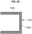
- FIGS. 4A, 4B and 4C illustrate sectional views taken along lines 4A-4A, 4B-4B, and 4C-4C of FIG. 3A .
- the top region 110a of at least one electrode assembly 110 may be positioned in a space formed by the first region 141 of the insulation member 140 and the rim part 141f at its periphery.
- FIG. 4A shows two electrode assemblies 110 are placed in the space, the embodiments are not limited thereto, and any suitable number of electrode assemblies may be used.
- the first region 141 with the rim part 141f has a u-shape, the opening of the "u" facing the top of the electrode assembly 110, the rim part 141 enclosing the top of the electrode assembly 110 therebetween.
- the opposite side regions 110c of the at least one electrode assembly 110 may be placed in a space formed by the second region back plate 142a and the second region lateral plate 142b.
- the second region lateral plates 142b extend from the second region back plate 142a at an angle, preferably extend perpendicularly from the second region back plate 142a.
- the uncoated region 111 a of the electrode assembly 110 may be placed in the space formed by the second region back plate 142a and the second region lateral plate 142b, and the uncoated region 111 a may be electrically connected to the collector plate 121.
- the second region 142 has a u-shape, the opening of the "u" enclosing the sides of the electrode assembly 110, preferably fully encloses the uncoated regions of the electrode assembly 110.
- the uncoated region 111 a may be welded to the collector plate 121.
- a reinforcing member 142c may be formed at a boundary or junction between the second region back plate 142a and the second region lateral plate 142b, thereby increasing bending resistance of the second region 142.
- the space formed by the second region back plate 142a and the second region lateral plate 142b may serve as a gas exhaustion path or passage.
- the generated gas may move upwardly along the second region 142 of the insulation member 140 to then be rapidly discharged to the outside of the secondary battery along the first region 141 of the insulation member 140 through the vent hole 141 a and the safety vent 161.
- the safety vent 161 may be ruptured by the gas pressure.
- the third region 143 may be bent from the second region 142 at substantially right angle during the manufacturing process of the secondary battery.
- the third region 143 may be thinner than the second region 142 for the purposes of facilitating bending and minimizing thickness increases in the overlapping regions between the third region 143 and the third region 143.
- the third region 143 preferably has a u-shape.
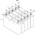
- FIG. 5 illustrates a perspective view of a state in which a plurality of secondary batteries are connected to each other in series by bus bars.
- the plurality of secondary batteries 100 may be stacked in a horizontal direction.
- Each of the plurality of secondary batteries 100 may include a first electrode terminal (e.g., positive electrode terminal) 120 and a second electrode terminal (e.g., negative electrode terminal) 130.
- the secondary batteries may be arranged such that opposite polarity terminals of adjacent secondary batteries face or are aligned with each other.
- the first electrode terminal 120 of one secondary battery may be electrically connected to the second electrode terminal 130 of another secondary battery adjacent thereto by bus bars 170.
- second fastening members 171 may be engaged with the first electrode terminal 120 and the second electrode terminal 130, respectively, so that the bus bars 170 are firmly coupled with the first electrode terminal 120 and the second electrode terminal 130.
- the plurality of secondary batteries 100 may be connected to each other in series through the bus bars 170.
- FIG. 5 shows that the plurality of secondary batteries 100 are connected to each other in series, in an implementation, they may be connected to each other in parallel.
- FIG. 6 illustrates a perspective view of an insulation member according to another embodiment.
- the insulation member 240 according to the present embodiment is similar to the insulation member 140 of the previous embodiment, except for the configuration of the third region 243. Accordingly, a repeated description of like elements is omitted.
- the insulation member 240 may include the third region 243.
- the third region 243 may include a third region back plate 243a and a third region lateral plate 243b.
- the third region 243 may extend from ends of the second region 142.
- the third region back plate 243a may extend from an end of the second region back plate 142a.
- a width of the third region back plate 243a may be narrower than a width of the second region back plate 142a. Accordingly, in an assembled condition (not illustrated), the third region 243 (including the third region back plate 243a and the third region lateral plate 243b) may be bent inwardly and may be encompassed by the second region 142 without interfering therewith.
- the embodiments provide a secondary battery having improved insulating properties between an electrode assembly and a case as well as facilitated exhaustion of the gas generated from the electrode assembly and/or electrolyte during overcharging.
- an insulation member may be formed at locations corresponding to opposite side regions and top and bottom regions of the electrode assembly.
- an electric short between the electrode assembly and the case may be reduced or prevented.
- the secondary battery according to an embodiment may help improve an insulating property between the electrode assembly and the case.
- opposing side regions and top and bottom regions of the electrode assembly may be substantially or mostly surrounded by the insulation member, thereby protecting the electrode assembly against external shocks in a secured manner.
- gas generated from the electrode assembly and/or electrolyte may be guided to a safety vent in the cap plate along a gas passage between the electrode assembly and the insulation member. Accordingly, when the secondary battery is overcharged, the safety vent may be opened rapidly and accurately due to the gas, thereby improving the reliability of the secondary battery with respect to overcharging.
- a terminal protrusion having an insulation member terminal hole in the insulation member may serve as an insulator that insulates the cap plate and the electrode terminal.
- an additional insulation member for insulating the cap plate and the electrode terminal may not be separately required.
- the insulation member may serve to insulate the electrode assembly from the case (or the cap plate) and to insulate the electrode terminal from the cap plate, thereby reducing the number of components.
Abstract
Description
- Embodiments relate to a secondary battery.
- Unlike a primary battery that is not chargeable, a secondary battery may be chargeable and dischargeable. Lower power secondary batteries may be made into battery packs and used as a power source for various portable electronic devices e.g. cellular phones or camcorders. Larger sized batteries having dozens of battery cells connected to each other may be used as the power source for a motor drive, e.g., in electric scooters or hybrid electric vehicles.
- The secondary batteries may be manufactured into various types, including cylindrical and prismatic types depending on the shape of a battery case. The secondary battery may be formed by accommodating an electrode assembly (having a positive electrode plate, a negative electrode plate, and a separator therebetween) with an electrolyte in a case, and installing a cap plate in the case. A positive electrode terminal and a negative electrode terminal may be connected to the electrode assembly and may be exposed or protrude outside through the cap plate.
- Embodiments are directed to a secondary battery.
- The embodiments may be realized by providing a secondary battery including an electrode assembly, the electrode assembly including an uncoated region at ends thereof; a case accommodating the electrode assembly; a cap plate coupled with the case; and an insulation member in the case, the insulation member including a first region between the electrode assembly and the cap plate, and a second region between the uncoated region of the electrode assembly and an inner surface of the case.
- The insulation member may be coupled with the cap plate.
- The first region may include a terminal protrusion in a cap plate terminal hole of the cap plate, the terminal protrusion including an insulation member terminal hole therethrough, and a coupling protrusion, the coupling protrusion being coupled with a coupling recess of the cap plate.
- The first region may further include a vent hole under a vent plate of the cap plate, an insulation member injection hole under a cap plate injection hole of the cap plate.
- The insulation member may form a gas passage that directs gas generated during charging/discharging of the secondary battery toward the vent hole.
- The first region may include a thick rim part extending downwardly along sides thereof.
- The second region may extend downwardly from ends of the first region.
- The second region may include a second region back plate between the uncoated region of the electrode assembly and a narrow side of the case, and a second region lateral plate extending inwardly from the second region back plate.
- The second region lateral plate may extend between sides of the uncoated region of the electrode assembly and a wide side of the case.
- The second region may include a reinforcing member at a junction between the second region back plate and the second region lateral plate.
- The second region back plate may have a width equal to or greater than a width of the uncoated region.
- The second region lateral plate may extend to cover an entire wide side of the electrode assembly.
- The insulation member may further include a third region opposite to the first region, the third region being between a bottom side of the electrode assembly and the inner surface of the case.
- The third region may extend inwardly from ends of the second region.
- The third region may include a third region bottom plate between the uncoated region of the electrode assembly and a bottom surface of the case.
- The third region bottom plate may have a width equal to or greater than a width of the uncoated region of the electrode assembly.
- The third region bottom plate may extend to cover an entire bottom side of the electrode assembly.
- The third region may be foldable from one position longitudinal with the second region in an unassembled condition to another position normal to the second region in an assembled condition.
- The insulation member may be formed from a phenol resin, polyphenylene sulfide, polyether ether ketone, polyether ketone, polyoxymethylene, or combinations thereof.
- The insulation member may have a one-piece, integrally formed structure.
- The above and other features and advantages will become more apparent to those of ordinary skill in the art by describing in detail exemplary embodiments with reference to the attached drawings, in which:
-
FIG. 1A illustrates a perspective view of a secondary battery according to an embodiment; -
FIG. 1B illustrates a sectional view of the secondary battery ofFIG. 1A ; -
FIG. 1C illustrates a partly enlarged view of the secondary battery ofFIG. 1B ; -
FIG. 2A illustrates a perspective view of an insulation member of the secondary battery ofFIG. 1A ; -
FIG. 2B illustrates a sectional view of the insulation member ofFIG. 2A ; -
FIG. 3A illustrates a perspective view of an unassembled condition of the insulation member ofFIG. 2A ; -
FIG. 3B illustrates a sectional view of the unassembled condition of the insulation member ofFIG. 2A ; -
FIGS. 4A, 4B and4C illustrate sectional views taken alonglines 4A-4A, 4B-4B, and 4C-4C ofFIG. 3A ; -
FIG. 5 illustrates a perspective view of a state in which a plurality of secondary batteries are connected to each other in series by bus bars; and -
FIG. 6 illustrates a perspective view of an insulation member according to another embodiment. - Example embodiments will now be described more fully hereinafter with reference to the accompanying drawings; however, they may be embodied in different forms and should not be construed as limited to the embodiments set forth herein. Rather, these embodiments are provided so that this disclosure will be thorough and complete, and will fully convey the scope of the invention to those skilled in the art.
- In the drawing figures, the dimensions of layers and regions may be exaggerated for clarity of illustration. It will also be understood that when a layer or element is referred to as being "on" another element, it can be directly on the other element, or intervening elements may also be present. Further, it will be understood that when an element is referred to as being "under" another element, it can be directly under, and one or more intervening elements may also be present. In addition, it will also be understood that when an element is referred to as being "between" two elements, it can be the only element between the two elements, or one or more intervening element may also be present. Like reference numerals refer to like elements throughout.
-
FIG. 1A illustrates a perspective view of a secondary battery according to an embodiment.FIG. 1B illustrates a sectional view of the secondary battery ofFIG. 1A .FIG. 1C illustrates a partly enlarged view of the secondary battery ofFIG. 1B . - As shown in
FIGS. 1A ,1B , and1C , the secondary battery according to an embodiment may include anelectrode assembly 110, a first electrode terminal 120 (e.g., a positive electrode terminal), a second electrode terminal 130 (e.g., a negative electrode terminal), aninsulation member 140, acase 150, and acap plate 160. - The
electrode assembly 110 may be formed by winding or laminating a stacked structure including afirst electrode plate 111, aseparator 113, and asecond electrode plate 112. In an implementation, thefirst electrode plate 111 may serve as a positive electrode and thesecond electrode plate 112 may serve as a negative electrode, or vice versa. In addition, theelectrode assembly 110 may have a substantially hexahedral shape having opposite side regions facing each other (an uncoated portion or region), a top region above the opposite side regions, and a bottom region opposite to the top region. - The
first electrode plate 111 may be formed by coating a first electrode active material (made from, e.g., a transition metal oxide) on a first electrode collector (made from a metallic foil, e.g. aluminum foil) and may include a first electrode uncoated region orportion 111 a that is not coated with the first electrode active material. The first electrodeuncoated portion 111 a may become a path of current flow between thefirst electrode plate 111 and an outside of thefirst electrode plate 111. The material of thefirst electrode plate 111 is not limited to those listed herein. - The
second electrode plate 112 may be formed by coating a second electrode active material (made from, e.g., graphite or a carbon material) on a second electrode collector (made from a metallic foil, e.g., copper or nickel) and may include a second electrode uncoated region orportion 112a that is not coated with the second electrode active material. The second electrodeuncoated portion 112a may become a path of current flow between thesecond electrode plate 112 and an outside of thesecond electrode plate 112. The material of thesecond electrode plate 112 is not limited to those listed herein. Thefirst electrode plate 111 and thesecond electrode plate 112 may have different polarities. - The
separator 113 may prevent an electric short between thefirst electrode plate 111 and thesecond electrode plate 112 and may allow only lithium ions to pass. Theseparator 113 may be formed from, e.g., polyethylene (PE), polypropylene (PP) or a composite film of polyethylene (PE) and polypropylene (PP). The material of theseparator 113 is not limited to those listed herein. - A
first electrode terminal 120 and a second electrode terminal 130 (electrically connected to thefirst electrode plate 111 and thesecond electrode plate 112, respectively) may be coupled with opposite ends of theelectrode assembly 110. - The
electrode assembly 110 may be accommodated in thecase 140 together with an electrolyte. The electrolyte may include a lithium salt (e.g., LiPF6 or LiBF4) and an organic solvent (e.g., ethylene carbonate (EC), propylene carbonate (PC), diethyl carbonate (DEC), ethyl methyl carbonate (EMC), or dimethyl carbonate (DMC)). In an implementation, the electrolyte may be in a liquid, solid, or gel phase. - The
first electrode terminal 120 may be made from a metal or equivalents thereof and may be electrically connected to thefirst electrode plate 111. Thefirst electrode terminal 120 may include afirst collector plate 121, afirst collector terminal 122, and afirst fastening member 123. - The
first collector plate 121 may contact the first electrodeuncoated portion 111 a that protrudes at one end of theelectrode assembly 110. Thefirst collector plate 121 may be welded to the first electrodeuncoated portion 111 a. Thefirst collector plate 121 may be substantially L-shaped and may include aterminal hole 121 d on a top portion thereof. Thefirst collector terminal 122 may be fitted into theterminal hole 121d. Thefirst collector plate 121 may be made from, e.g., aluminum, or an aluminum alloy. However, the material of thefirst collector plate 121 is not limited to those listed herein. - The
first collector terminal 122 may pass through the cap plate 160 (described below) and may extend and protrude upwardly by a predetermined length. In addition, thefirst collector terminal 122 may be electrically connected to thefirst collector plate 121 under thecap plate 160. Thefirst collector terminal 122 may have a laterally extendingflange 122a under thecap plate 160 to help prevent thefirst collector terminal 122 from being dislodged from thecap plate 160 as thefirst collector terminal 122 extends and protrudes upwardly from a top surface of thecap plate 160 by a predetermined length. A region of thefirst collector terminal 122 under theflange 122a may be fitted into theterminal hole 121d of thefirst collector plate 121 to then be riveted or welded therewith. In addition, a region of thefirst collector terminal 122 on theflange 122a may pass through thecap plate 160 and may extend and protrude upwardly by the predetermined length. Afirst fastening member 123 may be fixed at the extending and protruding region. In addition, a thread may be formed at an upper extending region of thefirst collector terminal 122, thereby facilitating coupling of thefirst fastening member 123 with thefirst collector terminal 122. Here, thefirst collector terminal 122 may be electrically isolated from or electrically connected to thecap plate 160. Thefirst collector terminal 122 may be formed from, e.g., aluminum, an aluminum alloy, and/or equivalents thereof. However, the material of thefirst collector terminal 122 is not limited thereto. - The
first fastening member 123 may have a substantially hexagonal nut shape and may include a centrally formed perforation hole in a substantially perpendicular direction to allow thefirst collector terminal 122 to pass therethrough and to be coupled thereto. Thefirst fastening member 123 may be formed from, e.g., stainless steel, aluminum, an aluminum alloy, copper, a copper alloy, and/or equivalents thereof. However, the material of thefirst fastening member 123 is not limited thereto. In addition, thefirst fastening member 123 may be electrically disconnected from or connected to thecap plate 151. - A first
lower insulation member 124 may be disposed between theflange 122a of thefirst collector terminal 122 and thecap plate 160. A firstupper insulation member 125 may be disposed between thecap plate 160 and thefirst fastening member 123. The firstlower insulation member 124 may electrically isolate theflange 122a of thefirst collector terminal 122 and thefirst collector plate 121 from thecap plate 160. The firstupper insulation member 125 may electrically isolate thecap plate 160 from thefirst fastening member 123. - The
second electrode terminal 130 may be formed from a metal or equivalents thereof and may be electrically connected to thesecond electrode plate 112. Thesecond electrode terminal 130 may include asecond collector plate 131, asecond collector terminal 132, and asecond fastening member 133. Thesecond electrode terminal 130 may have the same shape as thefirst electrode terminal 120, and a repeated detailed description thereof is omitted. Thesecond collector plate 131 and thesecond collector terminal 132 may be formed from, e.g., copper, a copper alloy, and/or equivalents thereof. However, the material of thesecond collector plate 131 and thesecond collector terminal 132 is not limited thereto. In addition, thesecond fastening member 133 may be formed from, e.g., stainless steel, aluminum, an aluminum alloy, copper, a copper alloy, and/or equivalents thereof. However, the material of thesecond fastening member 133 is not limited thereto. - The
insulation member 140 may roughly cover theelectrode assembly 110 to electrically insulate theelectrode assembly 110 from thecase 150. In addition, theinsulation member 140 may be disposed between each of the first andsecond electrode terminals cap plate 160. Thus, theinsulation member 140 may electrically insulate the first andsecond electrode terminals cap plate 160. - The
insulation member 140 may formed from a material that is not melted in an electrolyte, e.g., a material that does not react with electrolyte. For example, theinsulation member 140 may be formed from phenol resin, polyphenylene sulfide, polyether ether ketone, polyether ketone, polyoxymethylene, and/or equivalents thereof. However, the material of theinsulation member 140 is not limited thereto. - The
insulation member 140 may include afirst region 141 and asecond region 142. In an implementation, theinsulation member 140 may further include athird region 143. Theinsulation member 140 may have a one-piece, integrally formed structure. - The
first region 141 may be between atop region 110a of theelectrode assembly 110 and thecap plate 160 to electrically insulate thetop region 110a of theelectrode assembly 110 from thecap plate 160. For example, theinsulation member 140 may be coupled with thecap plate 160. - The
first region 141 may include aterminal protrusion 141 c corresponding to a location of a capplate terminal hole cap plate 160. Theterminal protrusion 141 c may include an insulationmember terminal hole 141 b therein to allow the pillar-shapedcurrent collector terminal - In an implementation, the
first region 141 may have avent hole 141 a at a location corresponding to, e.g., under, a relativelythin safety vent 161 in thecap plate 160. Thevent hole 141 a may allow gas (generated due to overcharge of the secondary battery) to be rapidly discharged outside of the secondary battery through thesafety vent 161. - The
first region 141 may include acoupling protrusion 141d coupled with acoupling recess 163 in thecap plate 160. Thecoupling protrusion 141d may help prevent theinsulation member 140 from being separated from thecap plate 160. - The
first region 141 may include an insulationmember injection hole 141 e at a location corresponding to, e.g., under, a capplate injection hole 164 in thecap plate 160. The insulationmember injection hole 141 e may allow an electrolyte to rapidly flow to theelectrode assembly 110 when the electrolyte is injected through the capplate injection hole 164. - The
second region 142 may extend downwardly from opposite ends of thefirst region 141, preferably angled with respect to thefirst region 141, more preferably perpendicular to thefirst region 141. Thesecond region 142 may be positioned betweenopposite side regions 110c of the electrode assembly 110 (e.g., theuncoated region 111 a and 111 b and side regions of the case, i.e., short-side portions or narrow sides 152). Therefore, thesecond region 142 may electrically insulate theopposite side regions 110c of theelectrode assembly 110 from thecase 150. For example, thesecond region 142 may be between thefirst collector plate 121 and one narrow side of thecase 150 and between thesecond collector plate 131 and another narrow side of thecase 150. Thus, the first andsecond collector plates narrow sides 152 of thecase 150. - The
third region 143 may extend from, e.g., ends of, thesecond region 142 to then be positioned between a bottom side orregion 110b of theelectrode assembly 110 and an inner surface of abottom side 153 of thecase 150. Therefore, thethird region 143 may electrically insulate thebottom region 110b of theelectrode assembly 110 from the inner surface of thecase 150. For example, thethird region 143 may be between theuncoated region electrode assembly 110, preferably fully covering the widths of theuncoated regions case 150 to electrically insulate theuncoated region case 150. - In an implementation, the
third region 143 may be elongated to be in proximity to or to overlap other, opposing, portions thereof. For example, thethird region 143 may extend to cover an entire bottom side of theelectrode assembly 110. - The
case 150 may be formed from a conductive metal, e.g., aluminum, an aluminum alloy, and/or nickel plated steel. Thecase 150 may have a substantially hexagonal or hexahedral shape and may include a top opening to receive thefirst electrode terminal 120 and thesecond electrode terminal 130. The opening of thecase 150 may be sealed by thecap plate 160, thereby protecting theelectrode assembly 110 and electrolyte placed within thecase 150 from external surroundings. Thecase 150 may have two wide side surfaces 151 (corresponding in location and size to two wide side surfaces of the electrode assembly 110), two narrow sides 152 (corresponding in location and size to the opposite side regions of the electrode assembly 110), and the bottom surface 153 (corresponding in location and size to a bottom region of the electrode assembly 110). In addition, an insulation coating layer (not shown) may be further formed on inner surfaces of thecase 150 and thecap plate 160. Thus, thecase 150 and thecap plate 160 may be more electrically insulated from theelectrode assembly 110, thefirst electrode terminal 120, and thesecond electrode terminal 130. Theinsulation member 140 is distinct from a coating layer on inner surfaces of the case and/or the cap plate. The insulation member is a separate element distinct from the case and the cap plate and not only a coating layer. A thickness of theinsulation member 140 is greater than that of the coating layer. For example, theinsulation member 140 has a thickness in the range of 0.4 mm to 1.0 mm, but the thickness of theinsulation member 140 is not limited thereto. - The
cap plate 160 may be coupled with and/or seal the opening of thecase 150 above the top region orside 110 of theelectrode assembly 110, thereby protecting theelectrode assembly 110 and electrolyte from external surroundings. Thecap plate 160 may include the relatively thin safety vent 161 (substantially centered on the cap plate 160) and capplate terminal holes cap plate 160 to allow thefirst collector terminal 122 and thesecond collector terminal 132 to pass therethrough. As described above, thevent hole 141 a may be formed in thefirst region 141 of theinsulation member 140 to correspond to thesafety vent 161. In addition, theterminal protrusion 141 c including the insulationmember terminal hole 141 b therethrough may correspond to theterminal holes cap plate 160. In addition, thecap plate 160 may include at least onecoupling recess 163 between thesafety vent 161 and theterminal holes coupling protrusion 141d may be formed at a location of thefirst region 141 that corresponds to the at least onecoupling recess 163 and thecoupling protrusion 141d may be coupled with thecoupling recess 163. In addition, thecap plate 160 may include the capplate injection hole 164 at a location spaced apart from thesafety vent 161, and aplug 165 may be coupled with the capplate injection hole 164. As described above, the insulationmember injection hole 141 e may be formed in thefirst region 141 at a location corresponding to the capplate injection hole 164. - The
cap plate 160 may be formed from the same material as thecase 150. Therefore, thecap plate 160 may be welded to thecase 150 by, e.g., laser welding. As described above, thecap plate 160 may be electrically connected thefirst electrode terminal 120 to have the same polarity as thefirst electrode terminal 120. Thus, thecap plate 160 and thecase 150 may have the same polarity. - As shown in
FIG. 1C , theterminal protrusion 141 c of theinsulation member 140 may be inserted into the capplate terminal hole 162a. The insulationmember terminal hole 141 b may extend through theterminal protrusion 141 c. Thefirst region 141 of theinsulation member 140 may closely contact a bottom surface of thecap plate 160. In addition, theupper insulation member 125 may closely contact thecap plate 160, and thelower insulation member 124 may closely contact a bottom surface of thefirst region 141 of theinsulation member 140. - The pillar-shaped
first collector terminal 122 of thefirst electrode terminal 120 may extend and pass through thelower insulation member 124, thefirst region 141 of theinsulation member 140, theterminal protrusion 141 c, and theupper insulation member 125. Thus, thefirst collector terminal 122 may be electrically insulated from thecap plate 160 by thelower insulation member 124, thefirst region 141 of theinsulation member 140, theterminal protrusion 141 c, and theupper insulation member 125. - When it is desired that the
first electrode terminal 120 and thecap plate 160 have the same polarity, a portion of thefirst fastening member 123 coupled to thefirst collector terminal 122 may extend to contact thecap plate 160. -
FIG. 2A illustrates a perspective view of an insulation member of the secondary battery ofFIG. 1A .FIG. 2B illustrates a sectional view of the insulation member ofFIG. 2A . - As shown in
FIGS. 2A and2B , theinsulation member 140 may include thefirst region 141, the second region 142 (extending from ends of the first region 141), and the third region 143 (extending from the second region 142). In the assembled condition, thethird region 143 may be substantially parallel with thefirst region 141. - In addition, the
vent hole 141a may be formed in thefirst region 141 in an area corresponding to thesafety vent 161 of thecap plate 160. In addition, theterminal protrusion 141 c including the insulationmember terminal hole 141 b may be formed at sides of thevent hole 141 a to allow the pillar-shaped first and secondcurrent collector terminals coupling protrusion 141d (corresponding in location and shape to thecoupling recess 163 of the cap plate 160) may be formed between thevent hole 141 a and theterminal protrusion 141 c. In addition, the insulationmember injection hole 141 e may be formed at the location corresponding to the capplate injection hole 164. Further, thefirst region 141 may include a relativelythick rim part 141f formed lengthwise along a periphery thereof. For example, therim part 141f may extend downwardly along sides of thefirst region 141. Therim part 141f may enhance a bending strength of thefirst region 141. In other words, thefirst region 141 with therim part 141f forms a u-shape, the "u" facing the top of theelectrode assembly 110. - The
second region 142 may include a substantially planar second region backplate 142a and a substantially planar second regionlateral plate 142b. The second region backplate 142a may be formed at a region facing theopposite side regions 110c, e.g., ends, of theelectrode assembly 110, and the second regionlateral plate 142b may extend from thefirst plate 142a to cover sides of theuncoated region electrode assembly 110, preferably to fully cover sides of theuncoated region electrode assembly 110. For example, the second region backplate 142a may correspond in size and location to thenarrow side 152 of thecase 150 and the second regionlateral plate 142b may extend along thewide side 151 of thecase 150, preferably fully extends along thewide side 151 of thecase 150. - In an implementation, the second region
lateral plate 142b may have a width equal to or greater than a width of theuncoated region lateral plate 142b may be elongated to partially or completely cover wide sides of theelectrode assembly 110. - The
third region 143 may include a third region back plate (or third region bottom plate )143a and a third regionlateral plate 143b. Theplates uncoated region electrode assembly 110. Theplates uncoated region electrode assembly 110. For example, the third region backplate 143a and the third regionlateral plate 143b may be elongated to be in proximity to or to overlap other, opposing, portions thereof. -
FIG. 3A illustrates a perspective view of an unassembled condition of the insulation member ofFIG. 2A .FIG. 3B illustrates a sectional view of the unassembled condition of the insulation member ofFIG. 2A . - As shown in
FIGS. 3A and3B , before theelectrode assembly 110 is coupled with theinsulation member 140, thethird region 143 may extend in parallel with thesecond region 142. However, once theelectrode assembly 110 is coupled with theinsulation member 140, thethird region 143 may be bent from thesecond region 142 at a substantially right angle. If thethird region 143 is bent in such a manner, the secondary battery may be manufactured in a simplified manner. For example, thefirst electrode terminal 120 and thesecond electrode terminal 130 may be electrically connected to theelectrode assembly 110 to then be coupled with theinsulation member 140. Here, theelectrode assembly 110 may be coupled with theinsulation member 140 in a direction from a bottom to a top of theinsulation member 140 shown inFIGS. 3A and3B . The pillar-shaped first andsecond collector terminal member terminal hole 141 b in thefirst region 141 of theinsulation member 140. Next, thethird region 143 may be bent at a substantially right angle with respect to thesecond region 142. In such a manner, thefirst region 141, thesecond region 142, and thethird region 143 may substantially cover theuncoated region second region 142 may also covercollector plates current collector terminals - According to the present embodiment, the second region
lateral plate 142b may also be bent from the second region backplate 142a. For example, the second regionlateral plate 142b may be bent at a predetermined angle with respect to the second region backplate 142a. Accordingly, the first andsecond collector plates current collector terminals first region 141 and thesecond region 142, and theelectrode assembly 110 may be placed in a space formed by thefirst region 141 and thesecond region 142. In such a state, the first andsecond collector plates uncoated region electrode assembly 110 may be welded to each other. Here, it is assumed that the first andsecond collector plates current collector terminals - In a state in which the second region
lateral plate 142b is pulled away from theelectrode assembly 110, the first andsecond collector plates uncoated region electrode assembly 110. Once the welding is performed, the second regionlateral plate 142b may again be in proximity to theuncoated region electrode assembly 110 due to a restoration force. - The
third region 143 may be foldable from one position longitudinal with thesecond region 142 in an unassembled condition to another position normal to thesecond region 142 in an assembled condition. -
FIGS. 4A, 4B and4C illustrate sectional views taken alonglines 4A-4A, 4B-4B, and 4C-4C ofFIG. 3A . - As shown in
FIG. 4A , thetop region 110a of at least oneelectrode assembly 110 may be positioned in a space formed by thefirst region 141 of theinsulation member 140 and therim part 141f at its periphery. AlthoughFIG. 4A shows twoelectrode assemblies 110 are placed in the space, the embodiments are not limited thereto, and any suitable number of electrode assemblies may be used. Thefirst region 141 with therim part 141f has a u-shape, the opening of the "u" facing the top of theelectrode assembly 110, therim part 141 enclosing the top of theelectrode assembly 110 therebetween. - As shown in
FIG. 4B , theopposite side regions 110c of the at least oneelectrode assembly 110 may be placed in a space formed by the second region backplate 142a and the second regionlateral plate 142b. The secondregion lateral plates 142b extend from the second region backplate 142a at an angle, preferably extend perpendicularly from the second region backplate 142a. In addition, theuncoated region 111 a of theelectrode assembly 110 may be placed in the space formed by the second region backplate 142a and the second regionlateral plate 142b, and theuncoated region 111 a may be electrically connected to thecollector plate 121. In other words, thesecond region 142 has a u-shape, the opening of the "u" enclosing the sides of theelectrode assembly 110, preferably fully encloses the uncoated regions of theelectrode assembly 110. In an implementation, theuncoated region 111 a may be welded to thecollector plate 121. Further, a reinforcingmember 142c may be formed at a boundary or junction between the second region backplate 142a and the second regionlateral plate 142b, thereby increasing bending resistance of thesecond region 142. In addition, the space formed by the second region backplate 142a and the second regionlateral plate 142b may serve as a gas exhaustion path or passage. Therefore, if gas is generated due to overcharge of the secondary battery, the generated gas may move upwardly along thesecond region 142 of theinsulation member 140 to then be rapidly discharged to the outside of the secondary battery along thefirst region 141 of theinsulation member 140 through thevent hole 141 a and thesafety vent 161. Here, thesafety vent 161 may be ruptured by the gas pressure. - As shown in
FIGs. 2 and4C , thethird region 143 may be bent from thesecond region 142 at substantially right angle during the manufacturing process of the secondary battery. Here, thethird region 143 may be thinner than thesecond region 142 for the purposes of facilitating bending and minimizing thickness increases in the overlapping regions between thethird region 143 and thethird region 143. Thethird region 143 preferably has a u-shape. -
FIG. 5 illustrates a perspective view of a state in which a plurality of secondary batteries are connected to each other in series by bus bars. - As shown in
FIG. 5 , the plurality ofsecondary batteries 100 may be stacked in a horizontal direction. Each of the plurality ofsecondary batteries 100 may include a first electrode terminal (e.g., positive electrode terminal) 120 and a second electrode terminal (e.g., negative electrode terminal) 130. The secondary batteries may be arranged such that opposite polarity terminals of adjacent secondary batteries face or are aligned with each other. - The
first electrode terminal 120 of one secondary battery may be electrically connected to thesecond electrode terminal 130 of another secondary battery adjacent thereto by bus bars 170. Further,second fastening members 171 may be engaged with thefirst electrode terminal 120 and thesecond electrode terminal 130, respectively, so that the bus bars 170 are firmly coupled with thefirst electrode terminal 120 and thesecond electrode terminal 130. In this way, the plurality ofsecondary batteries 100 may be connected to each other in series through the bus bars 170. - Although
FIG. 5 shows that the plurality ofsecondary batteries 100 are connected to each other in series, in an implementation, they may be connected to each other in parallel. -
FIG. 6 illustrates a perspective view of an insulation member according to another embodiment. - The
insulation member 240 according to the present embodiment is similar to theinsulation member 140 of the previous embodiment, except for the configuration of thethird region 243. Accordingly, a repeated description of like elements is omitted. - The
insulation member 240 according to the present embodiment may include thethird region 243. Thethird region 243 may include a third region backplate 243a and a third regionlateral plate 243b. Thethird region 243 may extend from ends of thesecond region 142. For example, the third region backplate 243a may extend from an end of the second region backplate 142a. A width of the third region backplate 243a may be narrower than a width of the second region backplate 142a. Accordingly, in an assembled condition (not illustrated), the third region 243 (including the third region backplate 243a and the third regionlateral plate 243b) may be bent inwardly and may be encompassed by thesecond region 142 without interfering therewith. - The embodiments provide a secondary battery having improved insulating properties between an electrode assembly and a case as well as facilitated exhaustion of the gas generated from the electrode assembly and/or electrolyte during overcharging.
- In the secondary battery according to an embodiment, an insulation member may be formed at locations corresponding to opposite side regions and top and bottom regions of the electrode assembly. Thus, an electric short between the electrode assembly and the case may be reduced or prevented. For example, the secondary battery according to an embodiment may help improve an insulating property between the electrode assembly and the case.
- In addition, in the secondary battery according to an embodiment, opposing side regions and top and bottom regions of the electrode assembly may be substantially or mostly surrounded by the insulation member, thereby protecting the electrode assembly against external shocks in a secured manner.
- Further, when the secondary battery according to an embodiment is overcharged, gas generated from the electrode assembly and/or electrolyte may be guided to a safety vent in the cap plate along a gas passage between the electrode assembly and the insulation member. Accordingly, when the secondary battery is overcharged, the safety vent may be opened rapidly and accurately due to the gas, thereby improving the reliability of the secondary battery with respect to overcharging.
- In addition, according to an embodiment, a terminal protrusion having an insulation member terminal hole in the insulation member may serve as an insulator that insulates the cap plate and the electrode terminal. Thus, an additional insulation member for insulating the cap plate and the electrode terminal may not be separately required. For example, in the secondary battery according to an embodiment, the insulation member may serve to insulate the electrode assembly from the case (or the cap plate) and to insulate the electrode terminal from the cap plate, thereby reducing the number of components.
- Example embodiments have been disclosed herein, and although specific terms are employed, they are used and are to be interpreted in a generic and descriptive sense only and not for purpose of limitation. In some instances, as would be apparent to one of ordinary skill in the art as of the filing of the present application, features, characteristics, and/or elements described in connection with a particular embodiment may be used singly or in combination with features, characteristics, and/or elements described in connection with other embodiments unless otherwise specifically indicated. Accordingly, it will be understood by those of skill in the art that various changes in form and details may be made without departing from the scope of the present invention as set forth in the following claims.
Claims (15)
- A secondary battery (100), comprising:an electrode assembly (110), the electrode assembly (110) including an uncoated region at ends thereof;a case (150) accommodating the electrode assembly (110);a cap plate (160) coupled with the case (150); andan insulation member (140) in the case (150), the insulation member (140) including:a first region (141) between the electrode assembly (110) and the cap plate (160), anda second region (142) between the uncoated region of the electrode assembly (110) and an inner surface of the case (150).
- The secondary battery (100) as claimed in claim 1, wherein the insulation member (140) is coupled with the cap plate (160).
- The secondary battery (100) as claimed in claim 1 or 2, wherein the first region (141) includes:a terminal protrusion (141 c) in a cap plate (160) terminal hole of the cap plate (160), the terminal protrusion (141 c) including an insulation member terminal hole (141 b) therethrough, anda coupling protrusion (141d), the coupling protrusion (141d) being coupled with a coupling recess (163) of the cap plate (160).
- The secondary battery (100) as claimed in claim 3, wherein the first region (141) further includes:a vent hole (141 a) under a vent plate (161) of the cap plate (160),an insulation member injection hole (141 e) under a cap plate injection hole (164) of the cap plate (160).
- The secondary battery (100) as claimed in claim 4, wherein the insulation member (140) forms a gas passage that directs gas generated during charging/discharging of the secondary battery (100) toward the vent hole (141 a).
- The secondary battery (100) as claimed in one of the previous claims, wherein the first region (141) includes a rim part (141 f) extending downwardly along sides thereof.
- The secondary battery (100) as claimed in claim 1, wherein the second region (142):extends downwardly from ends of the first region (141), preferably angled with respect to the first region (141), and/orincludes a second region back plate (142a) between the uncoated region of the electrode assembly (110) and a narrow side of the case (150), and a second region lateral plate (142b) extending inwardly from the second region back plate (142a).
- The secondary battery (100) as claimed in claim 7, wherein the second region lateral plate (142b):extends between sides of the uncoated region of the electrode assembly (110) and a wide side of the case (150), and/orextends to cover an entire wide side of the electrode assembly (110).
- The secondary battery (100) as claimed in claim 7 or 8, wherein the second region (142) includes a reinforcing member (142c) at a junction between the second region back plate (142a) and the second region lateral plate (142b).
- The secondary battery (100) as claimed in one of claims 7 to 9, wherein the second region back plate (142a) has a width equal to or greater than a width of the uncoated region.
- The secondary battery (100) as claimed in one of the previous claims, wherein the insulation member (140) further includes a third region (143) opposite to the first region (141), the third region (143) being between a bottom side of the electrode assembly (110) and the inner surface of the case (150).
- The secondary battery (100) as claimed in claim 11, wherein the third region (143) extends inwardly from ends of the second region (142) and/or is foldable from one position longitudinal with the second region (142) in an unassembled condition to another position normal to the second region (142) in an assembled condition.
- The secondary battery (100) as claimed in claim 11 or 12, wherein the third region (143) includes a third region bottom plate (143a) between the uncoated region of the electrode assembly (110) and a bottom surface of the case (150).
- The secondary battery (100) as claimed in claim 13, wherein the third region bottom plate:has a width equal to or greater than a width of the uncoated region of the electrode assembly (110), and/orextends to cover an entire bottom side of the electrode assembly (110).
- The secondary battery (100) as claimed in one of the previous claims, wherein the insulation member (140) is formed from a phenol resin, polyphenylene sulfide, polyether ether ketone, polyether ketone, polyoxymethylene, or combinations thereof and/orhas a one-piece, integrally formed structure.
Applications Claiming Priority (2)
| Application Number | Priority Date | Filing Date | Title |
|---|---|---|---|
| US201161511264P | 2011-07-25 | 2011-07-25 | |
| US13/344,892 US9472802B2 (en) | 2011-07-25 | 2012-01-06 | Secondary battery |
Publications (3)
| Publication Number | Publication Date |
|---|---|
| EP2551940A2 true EP2551940A2 (en) | 2013-01-30 |
| EP2551940A3 EP2551940A3 (en) | 2014-01-22 |
| EP2551940B1 EP2551940B1 (en) | 2018-02-14 |
Family
ID=45894323
Family Applications (1)
| Application Number | Title | Priority Date | Filing Date |
|---|---|---|---|
| EP12161635.3A Active EP2551940B1 (en) | 2011-07-25 | 2012-03-28 | Secondary battery |
Country Status (5)
| Country | Link |
|---|---|
| US (1) | US9472802B2 (en) |
| EP (1) | EP2551940B1 (en) |
| JP (1) | JP6158474B2 (en) |
| KR (1) | KR20130012539A (en) |
| CN (1) | CN102903883B (en) |
Cited By (7)
| Publication number | Priority date | Publication date | Assignee | Title |
|---|---|---|---|---|
| EP2770557A1 (en) * | 2013-02-21 | 2014-08-27 | Samsung SDI Co., Ltd. | Rechargeable battery |
| EP2874196A1 (en) * | 2013-11-15 | 2015-05-20 | Samsung SDI Co., Ltd. | Connection and insulation elements inside of a secondary battery |
| EP2945206A1 (en) * | 2014-05-15 | 2015-11-18 | Samsung SDI Co., Ltd. | Secondary battery and manufacturing method thereof |
| DE102015200911A1 (en) * | 2015-01-21 | 2016-07-21 | Robert Bosch Gmbh | Battery cell with plastic component, as well as battery |
| WO2016120358A1 (en) * | 2015-01-30 | 2016-08-04 | Robert Bosch Gmbh | Battery cell and battery system |
| WO2018094074A3 (en) * | 2016-11-16 | 2018-09-27 | Pacesetter, Inc. | Battery with enhanced resistance to dendrite formation |
| SE2250961A1 (en) * | 2022-08-12 | 2024-02-13 | Northvolt Ab | Battery cell with insulating element |
Families Citing this family (23)
| Publication number | Priority date | Publication date | Assignee | Title |
|---|---|---|---|---|
| JP6502609B2 (en) * | 2013-09-26 | 2019-04-17 | 株式会社Gsユアサ | Storage element |
| KR102197407B1 (en) | 2014-03-10 | 2020-12-31 | 삼성에스디아이 주식회사 | Rechargeable battery having insulating member |
| CN104091902B (en) * | 2014-07-15 | 2016-07-06 | 惠州威健锂能电子有限公司 | A kind of disposable lithium ion battery of heat shrinkable plastic film shell and manufacture method thereof |
| CN105428584B (en) | 2014-09-11 | 2020-05-01 | 株式会社杰士汤浅国际 | Electric storage element |
| KR102284572B1 (en) * | 2014-10-07 | 2021-08-03 | 삼성에스디아이 주식회사 | Rechargeable battery |
| KR102273643B1 (en) * | 2014-10-07 | 2021-07-07 | 삼성에스디아이 주식회사 | Rechargeable battery |
| JP6369562B2 (en) * | 2014-11-28 | 2018-08-08 | 株式会社豊田自動織機 | Power storage device |
| KR102483338B1 (en) | 2015-05-15 | 2023-01-02 | 삼성에스디아이 주식회사 | Secondary Battery |
| KR102496391B1 (en) | 2015-11-11 | 2023-02-06 | 삼성에스디아이 주식회사 | Secondary Battery |
| JP6620942B2 (en) * | 2016-08-26 | 2019-12-18 | トヨタ自動車株式会社 | Secondary battery |
| JP6460418B2 (en) * | 2016-10-31 | 2019-01-30 | トヨタ自動車株式会社 | Secondary battery |
| KR102246734B1 (en) * | 2016-11-01 | 2021-04-29 | 삼성에스디아이 주식회사 | Rechargeable battery |
| CN106410107A (en) * | 2016-11-29 | 2017-02-15 | 深圳市长盈精密技术股份有限公司 | Power battery cover plate and battery polar post assembly thereof |
| JP6938923B2 (en) * | 2017-01-20 | 2021-09-22 | 株式会社Gsユアサ | Power storage element |
| KR102390766B1 (en) * | 2017-05-22 | 2022-04-26 | 삼성에스디아이 주식회사 | Secondary battery |
| JP6962168B2 (en) * | 2017-12-12 | 2021-11-05 | 三洋電機株式会社 | Square secondary battery and its manufacturing method |
| JP7230537B2 (en) | 2018-01-31 | 2023-03-01 | 株式会社Gsユアサ | Storage element |
| JP7014655B2 (en) * | 2018-03-22 | 2022-02-01 | 本田技研工業株式会社 | Battery module and method of manufacturing battery module |
| CN110190339A (en) | 2019-03-01 | 2019-08-30 | 青海时代新能源科技有限公司 | Secondary cell |
| KR20200106694A (en) * | 2019-03-05 | 2020-09-15 | 삼성에스디아이 주식회사 | Secondary battery |
| KR20230064916A (en) * | 2021-11-04 | 2023-05-11 | 삼성에스디아이 주식회사 | Secondary Battery |
| WO2023097574A1 (en) * | 2021-12-01 | 2023-06-08 | 宁德时代新能源科技股份有限公司 | Battery cell and manufacturing method and device therefor, battery, and electrical apparatus |
| CN116581364B (en) * | 2023-06-15 | 2024-01-30 | 宁夏宝丰昱能科技有限公司 | Battery and method of manufacture |
Family Cites Families (19)
| Publication number | Priority date | Publication date | Assignee | Title |
|---|---|---|---|---|
| KR100570625B1 (en) | 2004-07-28 | 2006-04-12 | 삼성에스디아이 주식회사 | Secondary battery |
| KR100599709B1 (en) | 2004-07-28 | 2006-07-12 | 삼성에스디아이 주식회사 | Secondary battery |
| KR100627313B1 (en) | 2004-11-30 | 2006-09-25 | 삼성에스디아이 주식회사 | Secondary battery |
| JP4806270B2 (en) | 2006-02-21 | 2011-11-02 | 三洋電機株式会社 | Square battery |
| KR100922352B1 (en) | 2007-10-02 | 2009-10-21 | 삼성에스디아이 주식회사 | Rechargeable battery |
| JP2009087901A (en) * | 2007-10-03 | 2009-04-23 | Nec Tokin Corp | Sealed battery |
| JP2009152006A (en) | 2007-12-19 | 2009-07-09 | Toyota Motor Corp | Fuel battery |
| JP5274026B2 (en) | 2008-01-11 | 2013-08-28 | 三洋電機株式会社 | Square battery |
| KR100976452B1 (en) | 2008-01-23 | 2010-08-17 | 삼성에스디아이 주식회사 | Rechargeable battery |
| JP4470124B2 (en) | 2008-06-13 | 2010-06-02 | トヨタ自動車株式会社 | battery |
| KR101552904B1 (en) * | 2008-12-08 | 2015-09-14 | 삼성에스디아이 주식회사 | Rechargeable battery and battery module using thereof |
| KR101023104B1 (en) * | 2008-12-26 | 2011-03-24 | 에스비리모티브 주식회사 | Rechargeable battery |
| JP5257697B2 (en) * | 2009-06-12 | 2013-08-07 | トヨタ自動車株式会社 | battery |
| JP5537094B2 (en) | 2009-08-27 | 2014-07-02 | 株式会社東芝 | battery |
| JP2011049064A (en) | 2009-08-27 | 2011-03-10 | Toshiba Corp | Battery |
| US8697272B2 (en) | 2009-09-01 | 2014-04-15 | Samsung Sdi Co., Ltd. | Secondary battery having an insulating member |
| KR101097221B1 (en) | 2009-10-30 | 2011-12-21 | 에스비리모티브 주식회사 | Secondary Battery |
| KR101137363B1 (en) | 2009-11-16 | 2012-04-23 | 에스비리모티브 주식회사 | Secondary battery |
| JP5811456B2 (en) * | 2010-12-28 | 2015-11-11 | 株式会社Gsユアサ | Electricity storage element |
-
2012
- 2012-01-06 US US13/344,892 patent/US9472802B2/en active Active
- 2012-01-30 KR KR1020120009254A patent/KR20130012539A/en not_active Application Discontinuation
- 2012-02-22 CN CN201210042988.9A patent/CN102903883B/en active Active
- 2012-03-21 JP JP2012063428A patent/JP6158474B2/en active Active
- 2012-03-28 EP EP12161635.3A patent/EP2551940B1/en active Active
Non-Patent Citations (1)
| Title |
|---|
| None |
Cited By (20)
| Publication number | Priority date | Publication date | Assignee | Title |
|---|---|---|---|---|
| US9570780B2 (en) | 2013-02-21 | 2017-02-14 | Samsung Sdi Co., Ltd. | Rechargeable battery |
| EP2770557A1 (en) * | 2013-02-21 | 2014-08-27 | Samsung SDI Co., Ltd. | Rechargeable battery |
| CN104659324B (en) * | 2013-11-15 | 2019-11-12 | 三星Sdi株式会社 | Secondary cell |
| EP2874196A1 (en) * | 2013-11-15 | 2015-05-20 | Samsung SDI Co., Ltd. | Connection and insulation elements inside of a secondary battery |
| CN104659324A (en) * | 2013-11-15 | 2015-05-27 | 三星Sdi株式会社 | Secondary battery |
| US9666839B2 (en) | 2013-11-15 | 2017-05-30 | Samsung Sdi Co., Ltd. | Secondary battery |
| EP2945206A1 (en) * | 2014-05-15 | 2015-11-18 | Samsung SDI Co., Ltd. | Secondary battery and manufacturing method thereof |
| US9620746B2 (en) | 2014-05-15 | 2017-04-11 | Samsung Sdi Co., Ltd. | Secondary battery and manufacturing method thereof |
| DE102015200911A1 (en) * | 2015-01-21 | 2016-07-21 | Robert Bosch Gmbh | Battery cell with plastic component, as well as battery |
| WO2016120358A1 (en) * | 2015-01-30 | 2016-08-04 | Robert Bosch Gmbh | Battery cell and battery system |
| US10818958B2 (en) | 2015-01-30 | 2020-10-27 | Robert Bosch Gmbh | Battery cell and battery system |
| EP3514849A1 (en) * | 2016-11-16 | 2019-07-24 | Pacesetter, Inc. | Battery with enhanced resistance to dendrite formation |
| US10727454B2 (en) | 2016-11-16 | 2020-07-28 | Pacesetter, Inc. | Battery with enhanced resistance to dendrite formation |
| WO2018094074A3 (en) * | 2016-11-16 | 2018-09-27 | Pacesetter, Inc. | Battery with enhanced resistance to dendrite formation |
| US10868283B2 (en) | 2016-11-16 | 2020-12-15 | Pacesetter, Inc. | Battery with enhanced resistance to dendrite formation |
| US10964922B2 (en) | 2016-11-16 | 2021-03-30 | Pacesetter, Inc. | Battery with enhanced resistance to dendrite formation |
| US10964921B2 (en) | 2016-11-16 | 2021-03-30 | Pacesetter, Inc. | Battery with enhanced resistance to dendrite formation |
| US11735711B2 (en) | 2016-11-16 | 2023-08-22 | Pacesetter, Inc. | Battery with enhanced resistance to dendrite formation |
| SE2250961A1 (en) * | 2022-08-12 | 2024-02-13 | Northvolt Ab | Battery cell with insulating element |
| WO2024033500A1 (en) * | 2022-08-12 | 2024-02-15 | Northvolt Ab | Battery cell with insulating element |
Also Published As
| Publication number | Publication date |
|---|---|
| EP2551940B1 (en) | 2018-02-14 |
| JP2013026214A (en) | 2013-02-04 |
| US9472802B2 (en) | 2016-10-18 |
| CN102903883B (en) | 2016-12-07 |
| CN102903883A (en) | 2013-01-30 |
| KR20130012539A (en) | 2013-02-04 |
| US20130029188A1 (en) | 2013-01-31 |
| JP6158474B2 (en) | 2017-07-05 |
| EP2551940A3 (en) | 2014-01-22 |
Similar Documents
| Publication | Publication Date | Title |
|---|---|---|
| EP2551940B1 (en) | Secondary battery | |
| EP2490283B1 (en) | Rechargeable battery | |
| EP2495784B1 (en) | Secondary battery | |
| EP2958163B1 (en) | Rechargeable battery | |
| EP2958162B1 (en) | Secondary battery | |
| US8728644B2 (en) | Rechargeable battery | |
| EP2736097B1 (en) | Rechargeable battery and module of the same | |
| US9136524B2 (en) | Secondary battery | |
| US9012065B2 (en) | Secondary battery and battery pack having the same | |
| US8828571B2 (en) | Secondary battery | |
| US11289782B2 (en) | Secondary battery | |
| US11387528B2 (en) | Secondary battery | |
| US9570780B2 (en) | Rechargeable battery | |
| EP3451418B1 (en) | Secondary battery | |
| US10211446B2 (en) | Rechargeable battery | |
| US10038172B2 (en) | Rechargeable battery | |
| US9153809B2 (en) | Secondary battery including retainer for electrode assembly | |
| EP2642551B1 (en) | Secondary battery | |
| US9028999B2 (en) | Secondary battery | |
| KR20200131653A (en) | Secondary Battery |
Legal Events
| Date | Code | Title | Description |
|---|---|---|---|
| PUAI | Public reference made under article 153(3) epc to a published international application that has entered the european phase |
Free format text: ORIGINAL CODE: 0009012 |
|
| 17P | Request for examination filed |
Effective date: 20120328 |
|
| AK | Designated contracting states |
Kind code of ref document: A2 Designated state(s): AL AT BE BG CH CY CZ DE DK EE ES FI FR GB GR HR HU IE IS IT LI LT LU LV MC MK MT NL NO PL PT RO RS SE SI SK SM TR |
|
| AX | Request for extension of the european patent |
Extension state: BA ME |
|
| RAP1 | Party data changed (applicant data changed or rights of an application transferred) |
Owner name: SAMSUNG SDI CO., LTD. Owner name: ROBERT BOSCH GMBH |
|
| PUAL | Search report despatched |
Free format text: ORIGINAL CODE: 0009013 |
|
| AK | Designated contracting states |
Kind code of ref document: A3 Designated state(s): AL AT BE BG CH CY CZ DE DK EE ES FI FR GB GR HR HU IE IS IT LI LT LU LV MC MK MT NL NO PL PT RO RS SE SI SK SM TR |
|
| AX | Request for extension of the european patent |
Extension state: BA ME |
|
| RIC1 | Information provided on ipc code assigned before grant |
Ipc: H01M 10/04 20060101ALN20131219BHEP Ipc: H01M 10/0587 20100101ALN20131219BHEP Ipc: H01M 2/18 20060101ALI20131219BHEP Ipc: H01M 2/02 20060101ALI20131219BHEP Ipc: H01M 2/12 20060101ALI20131219BHEP Ipc: H01M 2/34 20060101AFI20131219BHEP Ipc: H01M 2/26 20060101ALN20131219BHEP |
|
| 17Q | First examination report despatched |
Effective date: 20160316 |
|
| RIC1 | Information provided on ipc code assigned before grant |
Ipc: H01M 2/18 20060101ALI20170721BHEP Ipc: H01M 10/0587 20100101ALN20170721BHEP Ipc: H01M 2/06 20060101ALI20170721BHEP Ipc: H01M 2/34 20060101AFI20170721BHEP Ipc: H01M 2/16 20060101ALN20170721BHEP Ipc: H01M 2/26 20060101ALN20170721BHEP Ipc: H01M 10/04 20060101ALN20170721BHEP Ipc: H01M 2/02 20060101ALI20170721BHEP Ipc: H01M 2/12 20060101ALN20170721BHEP |
|
| GRAP | Despatch of communication of intention to grant a patent |
Free format text: ORIGINAL CODE: EPIDOSNIGR1 |
|
| INTG | Intention to grant announced |
Effective date: 20170913 |
|
| GRAS | Grant fee paid |
Free format text: ORIGINAL CODE: EPIDOSNIGR3 |
|
| GRAA | (expected) grant |
Free format text: ORIGINAL CODE: 0009210 |
|
| AK | Designated contracting states |
Kind code of ref document: B1 Designated state(s): AL AT BE BG CH CY CZ DE DK EE ES FI FR GB GR HR HU IE IS IT LI LT LU LV MC MK MT NL NO PL PT RO RS SE SI SK SM TR |
|
| REG | Reference to a national code |
Ref country code: GB Ref legal event code: FG4D |
|
| REG | Reference to a national code |
Ref country code: CH Ref legal event code: EP |
|
| REG | Reference to a national code |
Ref country code: IE Ref legal event code: FG4D |
|
| REG | Reference to a national code |
Ref country code: DE Ref legal event code: R096 Ref document number: 602012042738 Country of ref document: DE Ref country code: AT Ref legal event code: REF Ref document number: 970408 Country of ref document: AT Kind code of ref document: T Effective date: 20180315 |
|
| REG | Reference to a national code |
Ref country code: FR Ref legal event code: PLFP Year of fee payment: 7 |
|
| REG | Reference to a national code |
Ref country code: NL Ref legal event code: MP Effective date: 20180214 |
|
| REG | Reference to a national code |
Ref country code: AT Ref legal event code: MK05 Ref document number: 970408 Country of ref document: AT Kind code of ref document: T Effective date: 20180214 |
|
| PG25 | Lapsed in a contracting state [announced via postgrant information from national office to epo] |
Ref country code: HR Free format text: LAPSE BECAUSE OF FAILURE TO SUBMIT A TRANSLATION OF THE DESCRIPTION OR TO PAY THE FEE WITHIN THE PRESCRIBED TIME-LIMIT Effective date: 20180214 Ref country code: LT Free format text: LAPSE BECAUSE OF FAILURE TO SUBMIT A TRANSLATION OF THE DESCRIPTION OR TO PAY THE FEE WITHIN THE PRESCRIBED TIME-LIMIT Effective date: 20180214 Ref country code: CY Free format text: LAPSE BECAUSE OF FAILURE TO SUBMIT A TRANSLATION OF THE DESCRIPTION OR TO PAY THE FEE WITHIN THE PRESCRIBED TIME-LIMIT Effective date: 20180214 Ref country code: ES Free format text: LAPSE BECAUSE OF FAILURE TO SUBMIT A TRANSLATION OF THE DESCRIPTION OR TO PAY THE FEE WITHIN THE PRESCRIBED TIME-LIMIT Effective date: 20180214 Ref country code: NL Free format text: LAPSE BECAUSE OF FAILURE TO SUBMIT A TRANSLATION OF THE DESCRIPTION OR TO PAY THE FEE WITHIN THE PRESCRIBED TIME-LIMIT Effective date: 20180214 Ref country code: NO Free format text: LAPSE BECAUSE OF FAILURE TO SUBMIT A TRANSLATION OF THE DESCRIPTION OR TO PAY THE FEE WITHIN THE PRESCRIBED TIME-LIMIT Effective date: 20180514 Ref country code: FI Free format text: LAPSE BECAUSE OF FAILURE TO SUBMIT A TRANSLATION OF THE DESCRIPTION OR TO PAY THE FEE WITHIN THE PRESCRIBED TIME-LIMIT Effective date: 20180214 |
|
| PG25 | Lapsed in a contracting state [announced via postgrant information from national office to epo] |
Ref country code: LV Free format text: LAPSE BECAUSE OF FAILURE TO SUBMIT A TRANSLATION OF THE DESCRIPTION OR TO PAY THE FEE WITHIN THE PRESCRIBED TIME-LIMIT Effective date: 20180214 Ref country code: AT Free format text: LAPSE BECAUSE OF FAILURE TO SUBMIT A TRANSLATION OF THE DESCRIPTION OR TO PAY THE FEE WITHIN THE PRESCRIBED TIME-LIMIT Effective date: 20180214 Ref country code: BG Free format text: LAPSE BECAUSE OF FAILURE TO SUBMIT A TRANSLATION OF THE DESCRIPTION OR TO PAY THE FEE WITHIN THE PRESCRIBED TIME-LIMIT Effective date: 20180514 Ref country code: GR Free format text: LAPSE BECAUSE OF FAILURE TO SUBMIT A TRANSLATION OF THE DESCRIPTION OR TO PAY THE FEE WITHIN THE PRESCRIBED TIME-LIMIT Effective date: 20180515 Ref country code: RS Free format text: LAPSE BECAUSE OF FAILURE TO SUBMIT A TRANSLATION OF THE DESCRIPTION OR TO PAY THE FEE WITHIN THE PRESCRIBED TIME-LIMIT Effective date: 20180214 Ref country code: SE Free format text: LAPSE BECAUSE OF FAILURE TO SUBMIT A TRANSLATION OF THE DESCRIPTION OR TO PAY THE FEE WITHIN THE PRESCRIBED TIME-LIMIT Effective date: 20180214 |
|
| PG25 | Lapsed in a contracting state [announced via postgrant information from national office to epo] |
Ref country code: RO Free format text: LAPSE BECAUSE OF FAILURE TO SUBMIT A TRANSLATION OF THE DESCRIPTION OR TO PAY THE FEE WITHIN THE PRESCRIBED TIME-LIMIT Effective date: 20180214 Ref country code: AL Free format text: LAPSE BECAUSE OF FAILURE TO SUBMIT A TRANSLATION OF THE DESCRIPTION OR TO PAY THE FEE WITHIN THE PRESCRIBED TIME-LIMIT Effective date: 20180214 Ref country code: PL Free format text: LAPSE BECAUSE OF FAILURE TO SUBMIT A TRANSLATION OF THE DESCRIPTION OR TO PAY THE FEE WITHIN THE PRESCRIBED TIME-LIMIT Effective date: 20180214 Ref country code: IT Free format text: LAPSE BECAUSE OF FAILURE TO SUBMIT A TRANSLATION OF THE DESCRIPTION OR TO PAY THE FEE WITHIN THE PRESCRIBED TIME-LIMIT Effective date: 20180214 Ref country code: EE Free format text: LAPSE BECAUSE OF FAILURE TO SUBMIT A TRANSLATION OF THE DESCRIPTION OR TO PAY THE FEE WITHIN THE PRESCRIBED TIME-LIMIT Effective date: 20180214 |
|
| REG | Reference to a national code |
Ref country code: CH Ref legal event code: PL |
|
| REG | Reference to a national code |
Ref country code: DE Ref legal event code: R097 Ref document number: 602012042738 Country of ref document: DE |
|
| PG25 | Lapsed in a contracting state [announced via postgrant information from national office to epo] |
Ref country code: SM Free format text: LAPSE BECAUSE OF FAILURE TO SUBMIT A TRANSLATION OF THE DESCRIPTION OR TO PAY THE FEE WITHIN THE PRESCRIBED TIME-LIMIT Effective date: 20180214 Ref country code: DK Free format text: LAPSE BECAUSE OF FAILURE TO SUBMIT A TRANSLATION OF THE DESCRIPTION OR TO PAY THE FEE WITHIN THE PRESCRIBED TIME-LIMIT Effective date: 20180214 Ref country code: CZ Free format text: LAPSE BECAUSE OF FAILURE TO SUBMIT A TRANSLATION OF THE DESCRIPTION OR TO PAY THE FEE WITHIN THE PRESCRIBED TIME-LIMIT Effective date: 20180214 Ref country code: SK Free format text: LAPSE BECAUSE OF FAILURE TO SUBMIT A TRANSLATION OF THE DESCRIPTION OR TO PAY THE FEE WITHIN THE PRESCRIBED TIME-LIMIT Effective date: 20180214 Ref country code: MC Free format text: LAPSE BECAUSE OF FAILURE TO SUBMIT A TRANSLATION OF THE DESCRIPTION OR TO PAY THE FEE WITHIN THE PRESCRIBED TIME-LIMIT Effective date: 20180214 |
|
| REG | Reference to a national code |
Ref country code: BE Ref legal event code: MM Effective date: 20180331 |
|
| PLBE | No opposition filed within time limit |
Free format text: ORIGINAL CODE: 0009261 |
|
| STAA | Information on the status of an ep patent application or granted ep patent |
Free format text: STATUS: NO OPPOSITION FILED WITHIN TIME LIMIT |
|
| REG | Reference to a national code |
Ref country code: IE Ref legal event code: MM4A |
|
| PG25 | Lapsed in a contracting state [announced via postgrant information from national office to epo] |
Ref country code: LU Free format text: LAPSE BECAUSE OF NON-PAYMENT OF DUE FEES Effective date: 20180328 |
|
| 26N | No opposition filed |
Effective date: 20181115 |
|
| PG25 | Lapsed in a contracting state [announced via postgrant information from national office to epo] |
Ref country code: IE Free format text: LAPSE BECAUSE OF NON-PAYMENT OF DUE FEES Effective date: 20180328 |
|
| PG25 | Lapsed in a contracting state [announced via postgrant information from national office to epo] |
Ref country code: BE Free format text: LAPSE BECAUSE OF NON-PAYMENT OF DUE FEES Effective date: 20180331 Ref country code: CH Free format text: LAPSE BECAUSE OF NON-PAYMENT OF DUE FEES Effective date: 20180331 Ref country code: SI Free format text: LAPSE BECAUSE OF FAILURE TO SUBMIT A TRANSLATION OF THE DESCRIPTION OR TO PAY THE FEE WITHIN THE PRESCRIBED TIME-LIMIT Effective date: 20180214 Ref country code: LI Free format text: LAPSE BECAUSE OF NON-PAYMENT OF DUE FEES Effective date: 20180331 |
|
| PG25 | Lapsed in a contracting state [announced via postgrant information from national office to epo] |
Ref country code: MT Free format text: LAPSE BECAUSE OF NON-PAYMENT OF DUE FEES Effective date: 20180328 |
|
| PG25 | Lapsed in a contracting state [announced via postgrant information from national office to epo] |
Ref country code: TR Free format text: LAPSE BECAUSE OF FAILURE TO SUBMIT A TRANSLATION OF THE DESCRIPTION OR TO PAY THE FEE WITHIN THE PRESCRIBED TIME-LIMIT Effective date: 20180214 |
|
| PG25 | Lapsed in a contracting state [announced via postgrant information from national office to epo] |
Ref country code: HU Free format text: LAPSE BECAUSE OF FAILURE TO SUBMIT A TRANSLATION OF THE DESCRIPTION OR TO PAY THE FEE WITHIN THE PRESCRIBED TIME-LIMIT; INVALID AB INITIO Effective date: 20120328 Ref country code: PT Free format text: LAPSE BECAUSE OF FAILURE TO SUBMIT A TRANSLATION OF THE DESCRIPTION OR TO PAY THE FEE WITHIN THE PRESCRIBED TIME-LIMIT Effective date: 20180214 |
|
| PG25 | Lapsed in a contracting state [announced via postgrant information from national office to epo] |
Ref country code: MK Free format text: LAPSE BECAUSE OF NON-PAYMENT OF DUE FEES Effective date: 20180214 |
|
| PG25 | Lapsed in a contracting state [announced via postgrant information from national office to epo] |
Ref country code: IS Free format text: LAPSE BECAUSE OF FAILURE TO SUBMIT A TRANSLATION OF THE DESCRIPTION OR TO PAY THE FEE WITHIN THE PRESCRIBED TIME-LIMIT Effective date: 20180614 |
|
| REG | Reference to a national code |
Ref country code: DE Ref legal event code: R079 Ref document number: 602012042738 Country of ref document: DE Free format text: PREVIOUS MAIN CLASS: H01M0002340000 Ipc: H01M0050572000 |
|
| PGFP | Annual fee paid to national office [announced via postgrant information from national office to epo] |
Ref country code: FR Payment date: 20230309 Year of fee payment: 12 |
|
| PGFP | Annual fee paid to national office [announced via postgrant information from national office to epo] |
Ref country code: GB Payment date: 20230223 Year of fee payment: 12 Ref country code: DE Payment date: 20230228 Year of fee payment: 12 |
|
| P01 | Opt-out of the competence of the unified patent court (upc) registered |
Effective date: 20230530 |