EP2551934A1 - Rechargeable battery - Google Patents
Rechargeable battery Download PDFInfo
- Publication number
- EP2551934A1 EP2551934A1 EP12151834A EP12151834A EP2551934A1 EP 2551934 A1 EP2551934 A1 EP 2551934A1 EP 12151834 A EP12151834 A EP 12151834A EP 12151834 A EP12151834 A EP 12151834A EP 2551934 A1 EP2551934 A1 EP 2551934A1
- Authority
- EP
- European Patent Office
- Prior art keywords
- case
- rechargeable battery
- portions
- curvature
- bottom portion
- Prior art date
- Legal status (The legal status is an assumption and is not a legal conclusion. Google has not performed a legal analysis and makes no representation as to the accuracy of the status listed.)
- Granted
Links
Images



Classifications
-
- H—ELECTRICITY
- H01—ELECTRIC ELEMENTS
- H01M—PROCESSES OR MEANS, e.g. BATTERIES, FOR THE DIRECT CONVERSION OF CHEMICAL ENERGY INTO ELECTRICAL ENERGY
- H01M50/00—Constructional details or processes of manufacture of the non-active parts of electrochemical cells other than fuel cells, e.g. hybrid cells
- H01M50/10—Primary casings; Jackets or wrappings
- H01M50/102—Primary casings; Jackets or wrappings characterised by their shape or physical structure
- H01M50/103—Primary casings; Jackets or wrappings characterised by their shape or physical structure prismatic or rectangular
-
- Y—GENERAL TAGGING OF NEW TECHNOLOGICAL DEVELOPMENTS; GENERAL TAGGING OF CROSS-SECTIONAL TECHNOLOGIES SPANNING OVER SEVERAL SECTIONS OF THE IPC; TECHNICAL SUBJECTS COVERED BY FORMER USPC CROSS-REFERENCE ART COLLECTIONS [XRACs] AND DIGESTS
- Y02—TECHNOLOGIES OR APPLICATIONS FOR MITIGATION OR ADAPTATION AGAINST CLIMATE CHANGE
- Y02E—REDUCTION OF GREENHOUSE GAS [GHG] EMISSIONS, RELATED TO ENERGY GENERATION, TRANSMISSION OR DISTRIBUTION
- Y02E60/00—Enabling technologies; Technologies with a potential or indirect contribution to GHG emissions mitigation
- Y02E60/10—Energy storage using batteries
Definitions
- the present invention relates to a rechargeable battery for inducing bending of a case under compression.
- a rechargeable battery can repeatedly perform charge and discharge, unlike a primary battery, and includes, for example, a nickel-hydrogen battery, a lithium battery, and a lithium ion battery, and is manufactured in a pack form to be widely used in a portable electronic device such as a mobile phone, a laptop computer, and a camcorder.
- the rechargeable battery includes an electrode assembly that is spiral-wound in a jelly roll form by stacking a positive electrode and a negative electrode with a separator interposed therebetween, a case that houses the electrode assembly together with an electrolyte solution, and a cap assembly that seals an upper opening of the case.
- the case is formed to be a cylinder or a square made of aluminum or an aluminum alloy.
- the case is compressed and changed by pressure applied in a direction perpendicular to a top-down direction of the squared case, the case is bent or folded in a random direction so it is difficult to control a short circuit mode of a cell.
- a positive electrode and a negative electrode can be short circuited inside an electrode assembly so the rechargeable battery can catch fire or explode.
- Embodiments of the present invention have been made in an effort to provide a rechargeable battery for preventing an internal short circuit of a cell by inducing bending of a case under compression.
- Embodiments of the present invention have further been made in an effort to provide a rechargeable battery for preventing burning and explosion under compression.
- a rechargeable battery comprising a case comprising a bottom portion and front and rear portions connected to the bottom portion by joint portions including internal curved surfaces, an electrode assembly in the case and a cap assembly closing the case, wherein the curved surfaces define a first portion A1 in a centre portion of the case and second portions A2 on either side of the first portion, wherein the second portions have a higher mechanical strength than the first portion with respect to a compression force applied to the sides of the case.
- the first portion may be symmetrically disposed about a centre of the case.
- the radius of curvature R2 of the internal curved surfaces connecting the bottom portion to the front or rear portions is greater in the second portions A2 than in the first portion A1 of the case.
- the external radius of curvature R0 of the external curved surface C3 connecting the exterior of the bottom portion to the exterior of the front or rear portions may be the same in both the first and second portions A1, A2.
- a thickness of the joint portions connecting the bottom portion to the front or rear portions may be greater in the second portions A2 than in the first portion A1 of the case.
- the bottom portion may have a first thickness (t1) that is greater than a second thickness (t2) of the front or rear portions.
- a third thickness (t3) of a first joint portion in the first portion A1 and a fourth thickness (t4) of a second joint portion in the second portions A2 are between the first and second thicknesses.
- the third and fourth thicknesses may be gradually reduced from the bottom portion towards the front or rear portions.
- the internal curved surfaces may be symmetrically arranged at both the front and rear portions.
- the radius of curvature of the internal curved surfaces connecting the bottom portion to the front and rear portions may be gradually reduced towards a centre portion of the case.
- the radius of curvature may be greatest at the ends of the case and smallest at the centre line of the case.
- the radius of curvature may be linearly reduced towards the centre line from both sides of the case.
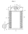
- the rechargeable battery includes an electrode assembly 10 for charging and discharging a current, a case 20 for receiving the electrode assembly 10 together with an electrolyte solution, and a cap assembly 30 for sealing an upper opening of the case 20.
- the electrode assembly 10 is formed by stacking a positive electrode 14 and a negative electrode 16 and spiral-winding the same in a jelly-roll form with a separator 15, which is an electrical insulator, therebetween.
- the electrode assembly 10 has a form that corresponds to an inner space of the case 20 so that it may be inserted into the case 20.
- the case 20 receives the electrode assembly 10 through an opening formed on one side, and is formed as a conductor so that it may function as an electrode terminal.
- the case 20 is made of aluminum or aluminum alloys, and is electrically connected to the positive electrode 14 of the electrode assembly 10 to work as a positive electrode terminal.
- an electrode terminal 31 installed in the cap assembly 30 is electrically connected to the negative electrode 16 of the electrode assembly 10 to function as a negative electrode terminal.
- the case 20 may work as a negative electrode terminal and the electrode terminal 31 may function as a positive electrode terminal.
- the cap assembly 30 includes a cap plate 32 fixed to the opening of the case 20, the electrode terminal 31 including an insulating gasket 33 and inserted into a terminal hole 32a of the cap plate 32, a terminal plate 34 electrically connected to the electrode terminal 31, an insulating plate 36 provided between the cap plate 32 and the terminal plate 34, and an insulating case 37 provided between the electrode assembly 10 and the cap assembly 30.
- the insulating gasket 33 electrically insulates the electrode terminal 31 and the cap plate 32 and seals a gap between them.
- the insulating plate 36 electrically insulates the terminal plate 34 and the cap plate 32 and seals a gap between them.
- the insulating case 37 electrically insulates the electrode assembly 10 and the cap assembly 30.
- a positive electrode lead 11 fixed to the positive electrode 14 of the electrode assembly 10 is welded inside the cap plate 32 to transmit the current of the positive electrode 14 to the cap plate 32 and the case 20. That is, the case 20 functions as a positive electrode terminal. That is, the insulating case 37 insulates the negative electrode 16 of the electrode assembly 10 and the cap plate 32 with positive polarity.
- a negative electrode lead 12 fixed to the negative electrode 16 of the electrode assembly 10 is welded on the bottom of the terminal plate 34 to transmit the current of the negative electrode 16 to the terminal plate 34 and the electrode terminal 31. That is, the electrode terminal 31 functions as a negative electrode terminal.
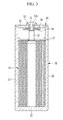
- FIG. 3 shows a cross-sectional view with respect to a line III-III when a rechargeable battery of FIG. 1 is assembled
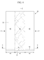
- FIG. 4 shows a side view of a case that is applicable to a rechargeable battery of FIG. 1 .
- the case 20 has an opening on one side to form a space for receiving the electrode assembly 10, and it is formed to be a square including a first surface 21 (hereinafter, a bottom surface) on the opposite side of the opening, a second surface (hereinafter, a front surface) 22 surrounding the opening and one side (a front portion) of the bottom surface 21, and a third surface (hereinafter, a back surface) 23 surrounding another side (a back portion).
- a first surface 21 hereinafter, a bottom surface
- a front surface 22 surrounding the opening and one side (a front portion) of the bottom surface 21, and a third surface (hereinafter, a back surface) 23 surrounding another side (a back portion).
- the case 20 according to the first exemplary embodiment is formed to have security of imparting no damage to the electrode assembly 10 for the compression condition where the case is compressed at the sides, which is also referred to herein as the side compression condition.
- the side compression condition represents that the case 20 is compressed and transformed by pressure (P) applied to the right and left sides of the case 20 in the direction perpendicular to the top-down direction in the squared case 20 (refer to FIG. 9 ).
- P pressure
- deformation of the case may occur in a longitudinal direction as a result of a lateral compression force applied to sides of the case.
- the case 20 is formed by deep drawing or pressing, and it is formed by connecting the bottom surface 21 and the front surface 22 with a curved surface and connecting the bottom surface 21 and the back surface 23 with a curved surface.
- the case 20 is formed to induce the bent or folded position of the case 20 to a predetermined point in order to prevent the internal short circuit of the electrode assembly 10 under compression.
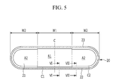
- FIG. 5 shows a cross-sectional view with respect to a line V - V of FIG. 4 .
- the case 20 is set to have different mechanical strengths for the side compression condition. That is, the case 20 includes a first area A1 with less mechanical strength for the side compression condition and a second area A2 with relatively greater mechanical strength than the first area A1.
- the areas A1, A2 have structures that provide different levels of resistance to a compression force applied to sides of the case.
- the first area A1 has a first width W1 with respect to the centre line (C) of the case 20.
- the second area A2 has second widths W2 and W2 set on both sides of the first area A1. That is, the first area A1 or the first and second areas A1 and A2 are symmetric with respect to the centre line (C) in the case 20.
- the case 20 sets curvatures of the curved surfaces that connect the bottom surface 21 and the front surface 22 and also the bottom surface 21 and the back surface 23 according to the first and second areas A1 and A2, and differently sets a thickness of the curved surface according to the first and second areas A1 and A2.
- the curvature of the curved surface connecting the bottom surface 21 and the front surface 22 and the curvature of the curved surface connecting the bottom surface 21 and the back surface 23 are the same so the curvature radius (radius of curvature) and comparison of thickness will be described by exemplifying the curved surface that connects the bottom surface 21 and the front surface 22. That is, the curved surface connecting the bottom surface 21 and the back surface 23 will not be described.
- FIG. 6 shows a cross-sectional view with respect to a line VI-VI of FIG. 5
- FIG. 7 shows a cross-sectional view with respect to a line VII-VII of FIG. 5 .
- a first thickness t1 of the bottom surface 21 is formed to be greater than a second thickness t2 of the front surface 22 (i.e., t1>t2) (where the thickness of the back surface is the same as the thickness of the front surface.)
- the case 20 having mechanical strength can induce bending depending on the mechanical strength of the front surface 22 and the back surface 23 without being influenced by the mechanical strength of the bottom surface 21 under the side compression condition. That is, the case 20 can induce bending in the first area A1 that is weak compared to the second area A2.
- the first thickness t1 of the bottom surface 21 is 0.4mm and the second thickness t2 of the front surface 22 is 0.25mm.
- the curved surface C1 connecting the bottom surface 21 and the front surface 22 in the first area A1 has a first curvature radius R1
- the curved surface C2 connecting the bottom surface 21 and the front surface 22 in the second area A2 has a second curvature radius R2.
- the first curvature radius R1 of the first area A1 is set to be less than the second curvature radius R2 of the second area A2.
- the first and second areas A1 and A2 are pressed with the second curvature radius R2 by using a punch with the relatively great second curvature radius R2, and the first area A1 is pressed with the first curvature radius R1 by additionally using a punch having the small first curvature radius R1.
- the first and second curvature radii R1 and R2 represent internal curvature radii of the curved surfaces C1 and C2 in the first and second areas A1 and A2.
- the external curvature radius R0 of the curved surface C3 connecting the bottom surface 21 and the front surface 22 is the same in the first and second areas A1 and A2.
- the curved surfaces C1 and C2 connecting the bottom surface 21 and the front surface 22 form a third thickness t3 with the first curvature radius R1 in the first area A1, and form a fourth thickness t4 with the second curvature radius R2 in the second area A2.
- the third and fourth thicknesses t3 and t4 are set to be between the first thickness t1 and the second thickness t2, and are gradually reduced toward the front surface 22 from the bottom surface 21.
- the third and fourth thicknesses t3 and t4 are shown at random positions in the curved surfaces C1 and C2.
- FIG. 8 shows a cross-sectional view for comparing a cross-section difference according to a curvature difference of FIG. 6 and FIG. 7 .
- the curved surfaces C1 and C2 connecting the bottom surface 21 and the front surface 22 have a cross-section difference ( ⁇ A) in the first and second areas A1 and A2.
- the second area A2 has greater mechanical strength than the first area A1 by the cross-section difference ( ⁇ A). Therefore, bending can be induced in the first area A1 that is set with respect to the centre line (C) of the case 20 under the side compression condition.
- the second area A2 is provided on both sides with respect to the centre line (C) of the case 20, and the first area A1 is partially provided between the second areas A2 so it is strong against cell swelling.
- the first and second areas A1 and A2 are formed with the same configuration in the front surface 22 and the back surface 23, so when they are bent with the front surface 22 of the case 20 as the inside and the back surface 23 as the outside or they are bent with the back surface 23 as the inside and the front surface 22 as the outside, they are bent in the same manner and the internal short circuit is prevented.
- FIG. 9 shows a perspective view of a rechargeable battery in a side compression condition according to a first exemplary embodiment of the present invention.
- the rechargeable battery is bent while the front surface 22 is set as the inside in the first area A1 of the case 20 and the back surface 23 as the outside. In this instance, the internal short circuit can be prevented in the rechargeable battery.
- FIG. 10 shows a cross-sectional view of a case for showing a curvature difference of a case in a rechargeable battery according to a second exemplary embodiment of the present invention.
- the same configuration as the first exemplary embodiment will be omitted.
- the case 20 has the first area A1 with the first curvature radius R1 in the centre in the width direction and has the second area A2 with the second curvature radius R2 on both sides of the first area A1.
- a case 220 according to the second exemplary embodiment has the first curvature radius R1, the minimum curvature, in correspondence to the centre line (C), and has the second curvature radius R2, the maximum curvature, on both sides.
- the curvature radius is linearly reduced toward the centre line (C) from the both sides of the case 220 (i.e., it is gradually reduced to the first curvature radius R1 from the second curvature radius R2).
- the cross-section difference ( ⁇ A, refer to FIG. 8 ) that is set by the curved surface (C4) (including the curved surface connecting a bottom surface 221 and a back surface 223) connecting the bottom surface 221 and a front surface 222 is linearly reduced toward the centre line (C) from both sides.
- the case 220 has the weakest mechanical strength at the centre line (C) so it efficiently prevents the internal short circuit of the cell since it is bent or folded near the centre line (C) under the side compression condition.
- the case 20 according to the first exemplary embodiment can be bent at somewhat different positions depending on the conditions within the range of the first area A1 under the side compression condition, and the case 220 according to the second exemplary embodiment sets the bending position more accurately since it is bent at the centre line (C) under the side compression condition.
Landscapes
- Chemical & Material Sciences (AREA)
- Chemical Kinetics & Catalysis (AREA)
- Electrochemistry (AREA)
- General Chemical & Material Sciences (AREA)
- Sealing Battery Cases Or Jackets (AREA)
- Connection Of Batteries Or Terminals (AREA)
- Secondary Cells (AREA)
Abstract
Description
- The present invention relates to a rechargeable battery for inducing bending of a case under compression.
- A rechargeable battery can repeatedly perform charge and discharge, unlike a primary battery, and includes, for example, a nickel-hydrogen battery, a lithium battery, and a lithium ion battery, and is manufactured in a pack form to be widely used in a portable electronic device such as a mobile phone, a laptop computer, and a camcorder. The rechargeable battery includes an electrode assembly that is spiral-wound in a jelly roll form by stacking a positive electrode and a negative electrode with a separator interposed therebetween, a case that houses the electrode assembly together with an electrolyte solution, and a cap assembly that seals an upper opening of the case.
- For example, the case is formed to be a cylinder or a square made of aluminum or an aluminum alloy. When the case is compressed and changed by pressure applied in a direction perpendicular to a top-down direction of the squared case, the case is bent or folded in a random direction so it is difficult to control a short circuit mode of a cell. In this instance, a positive electrode and a negative electrode can be short circuited inside an electrode assembly so the rechargeable battery can catch fire or explode.
- Embodiments of the present invention have been made in an effort to provide a rechargeable battery for preventing an internal short circuit of a cell by inducing bending of a case under compression.
- Embodiments of the present invention have further been made in an effort to provide a rechargeable battery for preventing burning and explosion under compression.
- According to the invention, there is provided a rechargeable battery comprising a case comprising a bottom portion and front and rear portions connected to the bottom portion by joint portions including internal curved surfaces, an electrode assembly in the case and a cap assembly closing the case, wherein the curved surfaces define a first portion A1 in a centre portion of the case and second portions A2 on either side of the first portion, wherein the second portions have a higher mechanical strength than the first portion with respect to a compression force applied to the sides of the case.
- The first portion may be symmetrically disposed about a centre of the case. The radius of curvature R2 of the internal curved surfaces connecting the bottom portion to the front or rear portions is greater in the second portions A2 than in the first portion A1 of the case.
- The external radius of curvature R0 of the external curved surface C3 connecting the exterior of the bottom portion to the exterior of the front or rear portions may be the same in both the first and second portions A1, A2.
- A thickness of the joint portions connecting the bottom portion to the front or rear portions may be greater in the second portions A2 than in the first portion A1 of the case.
- The bottom portion may have a first thickness (t1) that is greater than a second thickness (t2) of the front or rear portions.
- A third thickness (t3) of a first joint portion in the first portion A1 and a fourth thickness (t4) of a second joint portion in the second portions A2 are between the first and second thicknesses. The third and fourth thicknesses may be gradually reduced from the bottom portion towards the front or rear portions. The internal curved surfaces may be symmetrically arranged at both the front and rear portions.
- The radius of curvature of the internal curved surfaces connecting the bottom portion to the front and rear portions may be gradually reduced towards a centre portion of the case. The radius of curvature may be greatest at the ends of the case and smallest at the centre line of the case. The radius of curvature may be linearly reduced towards the centre line from both sides of the case.
- Embodiments of the invention will now be described by way of example with reference to the accompanying drawings, in which:
-
FIG. 1 shows an exploded perspective view of a rechargeable battery according to a first exemplary embodiment of the present invention. -
FIG. 2 shows a cross-sectional view with respect to a line II - II when a rechargeable battery ofFIG. 1 is assembled. -
FIG. 3 shows a cross-sectional view with respect to a line III-III when a rechargeable battery ofFIG. 1 is assembled. -
FIG. 4 shows a side view of a case applicable to a rechargeable battery ofFIG. 1 . -
FIG. 5 shows a cross-sectional view with respect to a line V - V ofFIG. 4 . -
FIG. 6 shows a cross-sectional view with respect to a line VI-VI ofFIG. 5 . -
FIG. 7 shows a cross-sectional view with respect to a line VII-VII ofFIG. 5 . -
FIG. 8 shows a cross-sectional view for comparing a cross-section difference according to a curvature difference ofFIG. 6 andFIG. 7 . -
FIG. 9 shows a perspective view of a rechargeable battery under compression according to a first exemplary embodiment of the present invention. -
FIG. 10 shows a cross-sectional view of a case for showing a curvature difference of a case in a rechargeable battery according to a second exemplary embodiment of the present invention. - Referring to
FIG. 1 andFIG. 2 , the rechargeable battery includes anelectrode assembly 10 for charging and discharging a current, acase 20 for receiving theelectrode assembly 10 together with an electrolyte solution, and acap assembly 30 for sealing an upper opening of thecase 20. - The
electrode assembly 10 is formed by stacking apositive electrode 14 and anegative electrode 16 and spiral-winding the same in a jelly-roll form with aseparator 15, which is an electrical insulator, therebetween. Theelectrode assembly 10 has a form that corresponds to an inner space of thecase 20 so that it may be inserted into thecase 20. - The
case 20 receives theelectrode assembly 10 through an opening formed on one side, and is formed as a conductor so that it may function as an electrode terminal. For example, thecase 20 is made of aluminum or aluminum alloys, and is electrically connected to thepositive electrode 14 of theelectrode assembly 10 to work as a positive electrode terminal. - In this instance, an
electrode terminal 31 installed in thecap assembly 30 is electrically connected to thenegative electrode 16 of theelectrode assembly 10 to function as a negative electrode terminal. On the contrary, thecase 20 may work as a negative electrode terminal and theelectrode terminal 31 may function as a positive electrode terminal. - The
cap assembly 30 includes acap plate 32 fixed to the opening of thecase 20, theelectrode terminal 31 including aninsulating gasket 33 and inserted into aterminal hole 32a of thecap plate 32, aterminal plate 34 electrically connected to theelectrode terminal 31, aninsulating plate 36 provided between thecap plate 32 and theterminal plate 34, and aninsulating case 37 provided between theelectrode assembly 10 and thecap assembly 30. - The
insulating gasket 33 electrically insulates theelectrode terminal 31 and thecap plate 32 and seals a gap between them. Theinsulating plate 36 electrically insulates theterminal plate 34 and thecap plate 32 and seals a gap between them. Theinsulating case 37 electrically insulates theelectrode assembly 10 and thecap assembly 30. - A
positive electrode lead 11 fixed to thepositive electrode 14 of theelectrode assembly 10 is welded inside thecap plate 32 to transmit the current of thepositive electrode 14 to thecap plate 32 and thecase 20. That is, thecase 20 functions as a positive electrode terminal. That is, theinsulating case 37 insulates thenegative electrode 16 of theelectrode assembly 10 and thecap plate 32 with positive polarity. - A
negative electrode lead 12 fixed to thenegative electrode 16 of theelectrode assembly 10 is welded on the bottom of theterminal plate 34 to transmit the current of thenegative electrode 16 to theterminal plate 34 and theelectrode terminal 31. That is, theelectrode terminal 31 functions as a negative electrode terminal. -
FIG. 3 shows a cross-sectional view with respect to a line III-III when a rechargeable battery ofFIG. 1 is assembled, andFIG. 4 shows a side view of a case that is applicable to a rechargeable battery ofFIG. 1 . - Referring to
FIG. 3 andFIG. 4 , thecase 20 has an opening on one side to form a space for receiving theelectrode assembly 10, and it is formed to be a square including a first surface 21 (hereinafter, a bottom surface) on the opposite side of the opening, a second surface (hereinafter, a front surface) 22 surrounding the opening and one side (a front portion) of thebottom surface 21, and a third surface (hereinafter, a back surface) 23 surrounding another side (a back portion). - The
case 20 according to the first exemplary embodiment is formed to have security of imparting no damage to theelectrode assembly 10 for the compression condition where the case is compressed at the sides, which is also referred to herein as the side compression condition. InFIG. 4 , the side compression condition represents that thecase 20 is compressed and transformed by pressure (P) applied to the right and left sides of thecase 20 in the direction perpendicular to the top-down direction in the squared case 20 (refer toFIG. 9 ). In other words, deformation of the case may occur in a longitudinal direction as a result of a lateral compression force applied to sides of the case. - As an example, the
case 20 is formed by deep drawing or pressing, and it is formed by connecting thebottom surface 21 and thefront surface 22 with a curved surface and connecting thebottom surface 21 and theback surface 23 with a curved surface. - The
case 20 is formed to induce the bent or folded position of thecase 20 to a predetermined point in order to prevent the internal short circuit of theelectrode assembly 10 under compression. -
FIG. 5 shows a cross-sectional view with respect to a line V - V ofFIG. 4 . Referring toFIG. 4 andFIG. 5 , thecase 20 is set to have different mechanical strengths for the side compression condition. That is, thecase 20 includes a first area A1 with less mechanical strength for the side compression condition and a second area A2 with relatively greater mechanical strength than the first area A1. In other words, the areas A1, A2 have structures that provide different levels of resistance to a compression force applied to sides of the case. - The first area A1 has a first width W1 with respect to the centre line (C) of the
case 20. The second area A2 has second widths W2 and W2 set on both sides of the first area A1. That is, the first area A1 or the first and second areas A1 and A2 are symmetric with respect to the centre line (C) in thecase 20. - As an example, the
case 20 sets curvatures of the curved surfaces that connect thebottom surface 21 and thefront surface 22 and also thebottom surface 21 and theback surface 23 according to the first and second areas A1 and A2, and differently sets a thickness of the curved surface according to the first and second areas A1 and A2. - The curvature of the curved surface connecting the
bottom surface 21 and thefront surface 22 and the curvature of the curved surface connecting thebottom surface 21 and theback surface 23 are the same so the curvature radius (radius of curvature) and comparison of thickness will be described by exemplifying the curved surface that connects thebottom surface 21 and thefront surface 22. That is, the curved surface connecting thebottom surface 21 and theback surface 23 will not be described. -
FIG. 6 shows a cross-sectional view with respect to a line VI-VI ofFIG. 5 , andFIG. 7 shows a cross-sectional view with respect to a line VII-VII ofFIG. 5 . - Referring to
FIG. 6 andFIG. 7 , regarding thecase 20, a first thickness t1 of thebottom surface 21 is formed to be greater than a second thickness t2 of the front surface 22 (i.e., t1>t2) (where the thickness of the back surface is the same as the thickness of the front surface.) - Therefore, the
case 20 having mechanical strength can induce bending depending on the mechanical strength of thefront surface 22 and theback surface 23 without being influenced by the mechanical strength of thebottom surface 21 under the side compression condition. That is, thecase 20 can induce bending in the first area A1 that is weak compared to the second area A2. For example, the first thickness t1 of thebottom surface 21 is 0.4mm and the second thickness t2 of thefront surface 22 is 0.25mm. - Referring to
FIG. 4 to FIG. 6 andFIG. 7 , the curved surface C1 connecting thebottom surface 21 and thefront surface 22 in the first area A1 has a first curvature radius R1, and the curved surface C2 connecting thebottom surface 21 and thefront surface 22 in the second area A2 has a second curvature radius R2. The first curvature radius R1 of the first area A1 is set to be less than the second curvature radius R2 of the second area A2. - For example, when the
case 20 is pressed and formed, the first and second areas A1 and A2 are pressed with the second curvature radius R2 by using a punch with the relatively great second curvature radius R2, and the first area A1 is pressed with the first curvature radius R1 by additionally using a punch having the small first curvature radius R1. - The first and second curvature radii R1 and R2 represent internal curvature radii of the curved surfaces C1 and C2 in the first and second areas A1 and A2. The external curvature radius R0 of the curved surface C3 connecting the
bottom surface 21 and thefront surface 22 is the same in the first and second areas A1 and A2. - Therefore, the curved surfaces C1 and C2 connecting the
bottom surface 21 and thefront surface 22 form a third thickness t3 with the first curvature radius R1 in the first area A1, and form a fourth thickness t4 with the second curvature radius R2 in the second area A2. - The third and fourth thicknesses t3 and t4 are set to be between the first thickness t1 and the second thickness t2, and are gradually reduced toward the
front surface 22 from thebottom surface 21. InFIG. 6 andFIG. 7 , the third and fourth thicknesses t3 and t4 are shown at random positions in the curved surfaces C1 and C2. -
FIG. 8 shows a cross-sectional view for comparing a cross-section difference according to a curvature difference ofFIG. 6 andFIG. 7 . Referring toFIG. 8 , the curved surfaces C1 and C2 connecting thebottom surface 21 and thefront surface 22 have a cross-section difference (ΔA) in the first and second areas A1 and A2. - That is, the second area A2 has greater mechanical strength than the first area A1 by the cross-section difference (ΔA). Therefore, bending can be induced in the first area A1 that is set with respect to the centre line (C) of the
case 20 under the side compression condition. - The second area A2 is provided on both sides with respect to the centre line (C) of the
case 20, and the first area A1 is partially provided between the second areas A2 so it is strong against cell swelling. - The first and second areas A1 and A2 are formed with the same configuration in the
front surface 22 and theback surface 23, so when they are bent with thefront surface 22 of thecase 20 as the inside and theback surface 23 as the outside or they are bent with theback surface 23 as the inside and thefront surface 22 as the outside, they are bent in the same manner and the internal short circuit is prevented. -
FIG. 9 shows a perspective view of a rechargeable battery in a side compression condition according to a first exemplary embodiment of the present invention. - Referring to
FIG. 9 , the rechargeable battery is bent while thefront surface 22 is set as the inside in the first area A1 of thecase 20 and theback surface 23 as the outside. In this instance, the internal short circuit can be prevented in the rechargeable battery. -
FIG. 10 shows a cross-sectional view of a case for showing a curvature difference of a case in a rechargeable battery according to a second exemplary embodiment of the present invention. In the description of the second exemplary embodiment, the same configuration as the first exemplary embodiment will be omitted. - In the first exemplary embodiment, the
case 20 has the first area A1 with the first curvature radius R1 in the centre in the width direction and has the second area A2 with the second curvature radius R2 on both sides of the first area A1. - However, a
case 220 according to the second exemplary embodiment has the first curvature radius R1, the minimum curvature, in correspondence to the centre line (C), and has the second curvature radius R2, the maximum curvature, on both sides. The curvature radius is linearly reduced toward the centre line (C) from the both sides of the case 220 (i.e., it is gradually reduced to the first curvature radius R1 from the second curvature radius R2). - That is, the cross-section difference (ΔA, refer to
FIG. 8 ) that is set by the curved surface (C4) (including the curved surface connecting abottom surface 221 and a back surface 223) connecting thebottom surface 221 and afront surface 222 is linearly reduced toward the centre line (C) from both sides. - Therefore, the
case 220 has the weakest mechanical strength at the centre line (C) so it efficiently prevents the internal short circuit of the cell since it is bent or folded near the centre line (C) under the side compression condition. - The
case 20 according to the first exemplary embodiment can be bent at somewhat different positions depending on the conditions within the range of the first area A1 under the side compression condition, and thecase 220 according to the second exemplary embodiment sets the bending position more accurately since it is bent at the centre line (C) under the side compression condition. - While this invention has been described in connection with what are presently considered to be practical exemplary embodiments, it is to be understood that the invention is not limited to the disclosed embodiments, but, on the contrary, is intended to cover various modifications and equivalent arrangements included within the scope of the appended claims.
Claims (12)
- A rechargeable battery comprising:a case (20, 220) comprising a bottom portion (221) and front and rear portions (222, 223) connected to the bottom portion (221) by joint portions including internal curved surfaces;an electrode assembly (10) in the case; anda cap assembly (30) closing the case;wherein the curved surfaces define a first portion A1 in a centre portion of the case and second portions A2 on either side of the first portion, wherein the second portions have a higher mechanical strength than the first portion with respect to a compression force applied to the sides of the case.
- The rechargeable battery of claim 1, wherein the first portion is symmetrically disposed about a centre of the case.
- The rechargeable battery of claim 1 or 2, wherein the radius of curvature R2 of the internal curved surfaces connecting the bottom portion (221) to the front or rear portions (222, 223) is greater in the second portions A2 than in the first portion A1 of the case.
- The rechargeable battery of claim 3, wherein the external radius of curvature R0 of the external curved surface C3 connecting the exterior of the bottom portion (221) to the exterior of the front or rear portions (222, 223) is the same in both the first and second portions A1, A2.
- The rechargeable battery of any one of the preceding claims, wherein a thickness of the joint portions connecting the bottom portion (221) to the front or rear portions (222, 223) is greater in the second portions A2 than in the first portion A1 of the case.
- The rechargeable battery of claim 5, wherein the bottom portion (221) has a first thickness (t1) that is greater than a second thickness (t2) of the front or rear portions (222, 223).
- The rechargeable battery of claim 6, wherein a third thickness (t3) of a first joint portion in the first portion A1 and a fourth thickness (t4) of a second joint portion in the second portions A2 are between the first and second thicknesses (t1, t2).
- The rechargeable battery of claim 7, wherein the third and fourth thicknesses are gradually reduced from the bottom portion towards the front or rear portions.
- The rechargeable battery of any one of the preceding claims, wherein the internal curved surfaces are symmetrically arranged at both the front and rear portions.
- The rechargeable battery of any one of the preceding claims, wherein the radius of curvature of the internal curved surfaces connecting the bottom portion (221) to the front and rear portions (222, 223) is gradually reduced towards a centre portion of the case.
- The rechargeable battery of claim 10, wherein the radius of curvature is greatest at the ends of the case and smallest at the centre line of the case.
- The rechargeable battery of claim 11, wherein the radius of curvature is linearly reduced towards the centre line from both sides of the case.
Applications Claiming Priority (2)
| Application Number | Priority Date | Filing Date | Title |
|---|---|---|---|
| US201161512764P | 2011-07-28 | 2011-07-28 | |
| US13/340,042 US9419252B2 (en) | 2011-07-28 | 2011-12-29 | Rechargeable battery |
Publications (2)
| Publication Number | Publication Date |
|---|---|
| EP2551934A1 true EP2551934A1 (en) | 2013-01-30 |
| EP2551934B1 EP2551934B1 (en) | 2018-12-05 |
Family
ID=45497892
Family Applications (1)
| Application Number | Title | Priority Date | Filing Date |
|---|---|---|---|
| EP12151834.4A Active EP2551934B1 (en) | 2011-07-28 | 2012-01-19 | Rechargeable battery |
Country Status (4)
| Country | Link |
|---|---|
| US (1) | US9419252B2 (en) |
| EP (1) | EP2551934B1 (en) |
| KR (1) | KR101925582B1 (en) |
| CN (1) | CN102903862B (en) |
Families Citing this family (5)
| Publication number | Priority date | Publication date | Assignee | Title |
|---|---|---|---|---|
| US9583741B2 (en) * | 2013-07-05 | 2017-02-28 | Samsung Sdi Co., Ltd. | Secondary battery |
| KR102198004B1 (en) | 2014-02-12 | 2021-01-04 | 삼성에스디아이 주식회사 | Battery pack |
| KR102296130B1 (en) * | 2014-08-13 | 2021-08-31 | 삼성에스디아이 주식회사 | Rechargeable battery |
| US9837682B1 (en) * | 2016-08-29 | 2017-12-05 | Microsoft Technology Licensing, Llc | Variable layer thickness in curved battery cell |
| CN217719778U (en) * | 2022-05-20 | 2022-11-01 | 宁德时代新能源科技股份有限公司 | Casing, battery monomer, battery and consumer |
Citations (5)
| Publication number | Priority date | Publication date | Assignee | Title |
|---|---|---|---|---|
| JP2001135282A (en) * | 1999-11-04 | 2001-05-18 | Nec Mobile Energy Kk | Sealed battery |
| KR20040074415A (en) * | 2003-02-18 | 2004-08-25 | 삼성에스디아이 주식회사 | Battery |
| EP2133933A1 (en) * | 2008-06-09 | 2009-12-16 | Samsung SDI Co., Ltd. | Secondary Battery |
| JP2010040181A (en) * | 2008-07-31 | 2010-02-18 | Toyota Motor Corp | Sealed battery and battery pack |
| EP2237341A1 (en) * | 2009-03-25 | 2010-10-06 | Samsung SDI Co., Ltd. | Secondary Battery |
Family Cites Families (9)
| Publication number | Priority date | Publication date | Assignee | Title |
|---|---|---|---|---|
| KR20030043407A (en) | 2001-11-28 | 2003-06-02 | 삼성에스디아이 주식회사 | Rectangular-type secondary battery |
| KR100601508B1 (en) * | 2004-09-22 | 2006-07-19 | 삼성에스디아이 주식회사 | Secondary battery with improved safety against longitudinal compression |
| KR100670492B1 (en) | 2004-11-29 | 2007-01-16 | 삼성에스디아이 주식회사 | Can for lithium secondary battery and lithium secondary battery using same |
| KR20060102751A (en) * | 2005-03-24 | 2006-09-28 | 삼성에스디아이 주식회사 | Lithium secondary battery |
| JP2006338992A (en) * | 2005-06-01 | 2006-12-14 | Nec Tokin Corp | Square lithium-ion battery |
| JP4402076B2 (en) * | 2006-05-30 | 2010-01-20 | 株式会社ワノテックジャパン | Battery can |
| KR100965718B1 (en) | 2008-10-08 | 2010-06-24 | 삼성에스디아이 주식회사 | Secondary battery |
| KR101621094B1 (en) | 2009-08-20 | 2016-05-16 | 삼성에스디아이 주식회사 | Secondary Battery |
| CN102074730A (en) | 2009-11-24 | 2011-05-25 | 欣旺达电子股份有限公司 | Thin-wall plastic frame battery using ultrasonic wave welding way and packaging method thereof |
-
2011
- 2011-12-29 US US13/340,042 patent/US9419252B2/en active Active
-
2012
- 2012-01-19 EP EP12151834.4A patent/EP2551934B1/en active Active
- 2012-07-26 CN CN201210262407.2A patent/CN102903862B/en active Active
- 2012-07-27 KR KR1020120082835A patent/KR101925582B1/en active Active
Patent Citations (5)
| Publication number | Priority date | Publication date | Assignee | Title |
|---|---|---|---|---|
| JP2001135282A (en) * | 1999-11-04 | 2001-05-18 | Nec Mobile Energy Kk | Sealed battery |
| KR20040074415A (en) * | 2003-02-18 | 2004-08-25 | 삼성에스디아이 주식회사 | Battery |
| EP2133933A1 (en) * | 2008-06-09 | 2009-12-16 | Samsung SDI Co., Ltd. | Secondary Battery |
| JP2010040181A (en) * | 2008-07-31 | 2010-02-18 | Toyota Motor Corp | Sealed battery and battery pack |
| EP2237341A1 (en) * | 2009-03-25 | 2010-10-06 | Samsung SDI Co., Ltd. | Secondary Battery |
Also Published As
| Publication number | Publication date |
|---|---|
| EP2551934B1 (en) | 2018-12-05 |
| US20130029208A1 (en) | 2013-01-31 |
| CN102903862A (en) | 2013-01-30 |
| US9419252B2 (en) | 2016-08-16 |
| KR20130014438A (en) | 2013-02-07 |
| CN102903862B (en) | 2016-03-16 |
| KR101925582B1 (en) | 2018-12-05 |
Similar Documents
| Publication | Publication Date | Title |
|---|---|---|
| EP2551935B1 (en) | Rechargeable battery | |
| US9246140B2 (en) | Rechargeable battery with a cap assembly having a first tab located outside of the case | |
| KR101217071B1 (en) | Rechargeable battery | |
| EP3046160B1 (en) | Rechargeable battery and pack of the same | |
| EP2385566A1 (en) | Rechargeable battery assembly | |
| US9142814B2 (en) | Rechargeable battery | |
| US20060141354A1 (en) | Can for a battery and battery using the same | |
| JP6669447B2 (en) | Secondary battery with cover | |
| CN104466049A (en) | Battery pack | |
| EP2273584B1 (en) | Lithium ion battery | |
| EP3062368B1 (en) | Rechargeable battery | |
| KR101890844B1 (en) | An electrode assembly with improved safety in use by structure of outermost electrodes and material of current collectors, and lithium ion battery with the electrode assembly | |
| JP2009245650A (en) | Sealed battery | |
| EP2899779A1 (en) | Secondary battery | |
| EP2551934B1 (en) | Rechargeable battery | |
| CN104282849B (en) | Secondary cell | |
| US9537134B2 (en) | Rechargeable battery | |
| EP3062367B1 (en) | Rechargeable battery | |
| KR102119049B1 (en) | Rechargeable battery having insulation case | |
| EP2385565A1 (en) | Rechargeable battery | |
| US20160043367A1 (en) | Rechargeable battery | |
| US12567657B2 (en) | Connecting lead and battery | |
| US20150236331A1 (en) | Secondary battery | |
| US10249861B2 (en) | Rechargeable battery | |
| KR20190060636A (en) | An electrode assembly with improved safety in use by structure of outermost electrodes and material of current collectors, and lithium ion battery with the electrode assembly |
Legal Events
| Date | Code | Title | Description |
|---|---|---|---|
| PUAI | Public reference made under article 153(3) epc to a published international application that has entered the european phase |
Free format text: ORIGINAL CODE: 0009012 |
|
| 17P | Request for examination filed |
Effective date: 20120321 |
|
| AK | Designated contracting states |
Kind code of ref document: A1 Designated state(s): AL AT BE BG CH CY CZ DE DK EE ES FI FR GB GR HR HU IE IS IT LI LT LU LV MC MK MT NL NO PL PT RO RS SE SI SK SM TR |
|
| AX | Request for extension of the european patent |
Extension state: BA ME |
|
| STAA | Information on the status of an ep patent application or granted ep patent |
Free format text: STATUS: EXAMINATION IS IN PROGRESS |
|
| 17Q | First examination report despatched |
Effective date: 20170523 |
|
| GRAP | Despatch of communication of intention to grant a patent |
Free format text: ORIGINAL CODE: EPIDOSNIGR1 |
|
| STAA | Information on the status of an ep patent application or granted ep patent |
Free format text: STATUS: GRANT OF PATENT IS INTENDED |
|
| INTG | Intention to grant announced |
Effective date: 20180717 |
|
| GRAS | Grant fee paid |
Free format text: ORIGINAL CODE: EPIDOSNIGR3 |
|
| GRAA | (expected) grant |
Free format text: ORIGINAL CODE: 0009210 |
|
| GRAA | (expected) grant |
Free format text: ORIGINAL CODE: 0009210 |
|
| STAA | Information on the status of an ep patent application or granted ep patent |
Free format text: STATUS: THE PATENT HAS BEEN GRANTED |
|
| AK | Designated contracting states |
Kind code of ref document: B1 Designated state(s): AL AT BE BG CH CY CZ DE DK EE ES FI FR GB GR HR HU IE IS IT LI LT LU LV MC MK MT NL NO PL PT RO RS SE SI SK SM TR |
|
| RAP1 | Party data changed (applicant data changed or rights of an application transferred) |
Owner name: SAMSUNG SDI CO., LTD. |
|
| REG | Reference to a national code |
Ref country code: GB Ref legal event code: FG4D |
|
| REG | Reference to a national code |
Ref country code: CH Ref legal event code: EP |
|
| REG | Reference to a national code |
Ref country code: AT Ref legal event code: REF Ref document number: 1074166 Country of ref document: AT Kind code of ref document: T Effective date: 20181215 |
|
| REG | Reference to a national code |
Ref country code: IE Ref legal event code: FG4D |
|
| REG | Reference to a national code |
Ref country code: DE Ref legal event code: R096 Ref document number: 602012054235 Country of ref document: DE |
|
| REG | Reference to a national code |
Ref country code: NL Ref legal event code: MP Effective date: 20181205 |
|
| REG | Reference to a national code |
Ref country code: AT Ref legal event code: MK05 Ref document number: 1074166 Country of ref document: AT Kind code of ref document: T Effective date: 20181205 |
|
| REG | Reference to a national code |
Ref country code: LT Ref legal event code: MG4D |
|
| PG25 | Lapsed in a contracting state [announced via postgrant information from national office to epo] |
Ref country code: FI Free format text: LAPSE BECAUSE OF FAILURE TO SUBMIT A TRANSLATION OF THE DESCRIPTION OR TO PAY THE FEE WITHIN THE PRESCRIBED TIME-LIMIT Effective date: 20181205 Ref country code: LT Free format text: LAPSE BECAUSE OF FAILURE TO SUBMIT A TRANSLATION OF THE DESCRIPTION OR TO PAY THE FEE WITHIN THE PRESCRIBED TIME-LIMIT Effective date: 20181205 Ref country code: HR Free format text: LAPSE BECAUSE OF FAILURE TO SUBMIT A TRANSLATION OF THE DESCRIPTION OR TO PAY THE FEE WITHIN THE PRESCRIBED TIME-LIMIT Effective date: 20181205 Ref country code: BG Free format text: LAPSE BECAUSE OF FAILURE TO SUBMIT A TRANSLATION OF THE DESCRIPTION OR TO PAY THE FEE WITHIN THE PRESCRIBED TIME-LIMIT Effective date: 20190305 Ref country code: LV Free format text: LAPSE BECAUSE OF FAILURE TO SUBMIT A TRANSLATION OF THE DESCRIPTION OR TO PAY THE FEE WITHIN THE PRESCRIBED TIME-LIMIT Effective date: 20181205 Ref country code: AT Free format text: LAPSE BECAUSE OF FAILURE TO SUBMIT A TRANSLATION OF THE DESCRIPTION OR TO PAY THE FEE WITHIN THE PRESCRIBED TIME-LIMIT Effective date: 20181205 Ref country code: ES Free format text: LAPSE BECAUSE OF FAILURE TO SUBMIT A TRANSLATION OF THE DESCRIPTION OR TO PAY THE FEE WITHIN THE PRESCRIBED TIME-LIMIT Effective date: 20181205 Ref country code: NO Free format text: LAPSE BECAUSE OF FAILURE TO SUBMIT A TRANSLATION OF THE DESCRIPTION OR TO PAY THE FEE WITHIN THE PRESCRIBED TIME-LIMIT Effective date: 20190305 |
|
| PG25 | Lapsed in a contracting state [announced via postgrant information from national office to epo] |
Ref country code: AL Free format text: LAPSE BECAUSE OF FAILURE TO SUBMIT A TRANSLATION OF THE DESCRIPTION OR TO PAY THE FEE WITHIN THE PRESCRIBED TIME-LIMIT Effective date: 20181205 Ref country code: RS Free format text: LAPSE BECAUSE OF FAILURE TO SUBMIT A TRANSLATION OF THE DESCRIPTION OR TO PAY THE FEE WITHIN THE PRESCRIBED TIME-LIMIT Effective date: 20181205 Ref country code: GR Free format text: LAPSE BECAUSE OF FAILURE TO SUBMIT A TRANSLATION OF THE DESCRIPTION OR TO PAY THE FEE WITHIN THE PRESCRIBED TIME-LIMIT Effective date: 20190306 Ref country code: SE Free format text: LAPSE BECAUSE OF FAILURE TO SUBMIT A TRANSLATION OF THE DESCRIPTION OR TO PAY THE FEE WITHIN THE PRESCRIBED TIME-LIMIT Effective date: 20181205 |
|
| PG25 | Lapsed in a contracting state [announced via postgrant information from national office to epo] |
Ref country code: NL Free format text: LAPSE BECAUSE OF FAILURE TO SUBMIT A TRANSLATION OF THE DESCRIPTION OR TO PAY THE FEE WITHIN THE PRESCRIBED TIME-LIMIT Effective date: 20181205 |
|
| PG25 | Lapsed in a contracting state [announced via postgrant information from national office to epo] |
Ref country code: IT Free format text: LAPSE BECAUSE OF FAILURE TO SUBMIT A TRANSLATION OF THE DESCRIPTION OR TO PAY THE FEE WITHIN THE PRESCRIBED TIME-LIMIT Effective date: 20181205 Ref country code: PT Free format text: LAPSE BECAUSE OF FAILURE TO SUBMIT A TRANSLATION OF THE DESCRIPTION OR TO PAY THE FEE WITHIN THE PRESCRIBED TIME-LIMIT Effective date: 20190405 Ref country code: CZ Free format text: LAPSE BECAUSE OF FAILURE TO SUBMIT A TRANSLATION OF THE DESCRIPTION OR TO PAY THE FEE WITHIN THE PRESCRIBED TIME-LIMIT Effective date: 20181205 Ref country code: PL Free format text: LAPSE BECAUSE OF FAILURE TO SUBMIT A TRANSLATION OF THE DESCRIPTION OR TO PAY THE FEE WITHIN THE PRESCRIBED TIME-LIMIT Effective date: 20181205 |
|
| PG25 | Lapsed in a contracting state [announced via postgrant information from national office to epo] |
Ref country code: SK Free format text: LAPSE BECAUSE OF FAILURE TO SUBMIT A TRANSLATION OF THE DESCRIPTION OR TO PAY THE FEE WITHIN THE PRESCRIBED TIME-LIMIT Effective date: 20181205 Ref country code: RO Free format text: LAPSE BECAUSE OF FAILURE TO SUBMIT A TRANSLATION OF THE DESCRIPTION OR TO PAY THE FEE WITHIN THE PRESCRIBED TIME-LIMIT Effective date: 20181205 Ref country code: IS Free format text: LAPSE BECAUSE OF FAILURE TO SUBMIT A TRANSLATION OF THE DESCRIPTION OR TO PAY THE FEE WITHIN THE PRESCRIBED TIME-LIMIT Effective date: 20190405 Ref country code: EE Free format text: LAPSE BECAUSE OF FAILURE TO SUBMIT A TRANSLATION OF THE DESCRIPTION OR TO PAY THE FEE WITHIN THE PRESCRIBED TIME-LIMIT Effective date: 20181205 Ref country code: SM Free format text: LAPSE BECAUSE OF FAILURE TO SUBMIT A TRANSLATION OF THE DESCRIPTION OR TO PAY THE FEE WITHIN THE PRESCRIBED TIME-LIMIT Effective date: 20181205 |
|
| REG | Reference to a national code |
Ref country code: CH Ref legal event code: PL |
|
| REG | Reference to a national code |
Ref country code: DE Ref legal event code: R097 Ref document number: 602012054235 Country of ref document: DE |
|
| PG25 | Lapsed in a contracting state [announced via postgrant information from national office to epo] |
Ref country code: LU Free format text: LAPSE BECAUSE OF NON-PAYMENT OF DUE FEES Effective date: 20190119 |
|
| PLBE | No opposition filed within time limit |
Free format text: ORIGINAL CODE: 0009261 |
|
| STAA | Information on the status of an ep patent application or granted ep patent |
Free format text: STATUS: NO OPPOSITION FILED WITHIN TIME LIMIT |
|
| REG | Reference to a national code |
Ref country code: BE Ref legal event code: MM Effective date: 20190131 |
|
| REG | Reference to a national code |
Ref country code: IE Ref legal event code: MM4A |
|
| PG25 | Lapsed in a contracting state [announced via postgrant information from national office to epo] |
Ref country code: DK Free format text: LAPSE BECAUSE OF FAILURE TO SUBMIT A TRANSLATION OF THE DESCRIPTION OR TO PAY THE FEE WITHIN THE PRESCRIBED TIME-LIMIT Effective date: 20181205 Ref country code: SI Free format text: LAPSE BECAUSE OF FAILURE TO SUBMIT A TRANSLATION OF THE DESCRIPTION OR TO PAY THE FEE WITHIN THE PRESCRIBED TIME-LIMIT Effective date: 20181205 Ref country code: MC Free format text: LAPSE BECAUSE OF FAILURE TO SUBMIT A TRANSLATION OF THE DESCRIPTION OR TO PAY THE FEE WITHIN THE PRESCRIBED TIME-LIMIT Effective date: 20181205 |
|
| 26N | No opposition filed |
Effective date: 20190906 |
|
| PG25 | Lapsed in a contracting state [announced via postgrant information from national office to epo] |
Ref country code: BE Free format text: LAPSE BECAUSE OF NON-PAYMENT OF DUE FEES Effective date: 20190131 |
|
| PG25 | Lapsed in a contracting state [announced via postgrant information from national office to epo] |
Ref country code: LI Free format text: LAPSE BECAUSE OF NON-PAYMENT OF DUE FEES Effective date: 20190131 Ref country code: CH Free format text: LAPSE BECAUSE OF NON-PAYMENT OF DUE FEES Effective date: 20190131 |
|
| PG25 | Lapsed in a contracting state [announced via postgrant information from national office to epo] |
Ref country code: IE Free format text: LAPSE BECAUSE OF NON-PAYMENT OF DUE FEES Effective date: 20190119 |
|
| PG25 | Lapsed in a contracting state [announced via postgrant information from national office to epo] |
Ref country code: TR Free format text: LAPSE BECAUSE OF FAILURE TO SUBMIT A TRANSLATION OF THE DESCRIPTION OR TO PAY THE FEE WITHIN THE PRESCRIBED TIME-LIMIT Effective date: 20181205 |
|
| PG25 | Lapsed in a contracting state [announced via postgrant information from national office to epo] |
Ref country code: MT Free format text: LAPSE BECAUSE OF NON-PAYMENT OF DUE FEES Effective date: 20190119 |
|
| REG | Reference to a national code |
Ref country code: DE Ref legal event code: R079 Ref document number: 602012054235 Country of ref document: DE Free format text: PREVIOUS MAIN CLASS: H01M0002020000 Ipc: H01M0050100000 |
|
| PG25 | Lapsed in a contracting state [announced via postgrant information from national office to epo] |
Ref country code: CY Free format text: LAPSE BECAUSE OF FAILURE TO SUBMIT A TRANSLATION OF THE DESCRIPTION OR TO PAY THE FEE WITHIN THE PRESCRIBED TIME-LIMIT Effective date: 20181205 |
|
| PG25 | Lapsed in a contracting state [announced via postgrant information from national office to epo] |
Ref country code: HU Free format text: LAPSE BECAUSE OF FAILURE TO SUBMIT A TRANSLATION OF THE DESCRIPTION OR TO PAY THE FEE WITHIN THE PRESCRIBED TIME-LIMIT; INVALID AB INITIO Effective date: 20120119 |
|
| PG25 | Lapsed in a contracting state [announced via postgrant information from national office to epo] |
Ref country code: MK Free format text: LAPSE BECAUSE OF FAILURE TO SUBMIT A TRANSLATION OF THE DESCRIPTION OR TO PAY THE FEE WITHIN THE PRESCRIBED TIME-LIMIT Effective date: 20181205 |
|
| P01 | Opt-out of the competence of the unified patent court (upc) registered |
Effective date: 20230528 |
|
| PGFP | Annual fee paid to national office [announced via postgrant information from national office to epo] |
Ref country code: FR Payment date: 20251231 Year of fee payment: 15 |
|
| PGFP | Annual fee paid to national office [announced via postgrant information from national office to epo] |
Ref country code: GB Payment date: 20260106 Year of fee payment: 15 |
|
| PGFP | Annual fee paid to national office [announced via postgrant information from national office to epo] |
Ref country code: DE Payment date: 20251230 Year of fee payment: 15 |