EP2551861B1 - Resistance welding high frequency transformer and spot welding machine - Google Patents
Resistance welding high frequency transformer and spot welding machine Download PDFInfo
- Publication number
- EP2551861B1 EP2551861B1 EP10848206.8A EP10848206A EP2551861B1 EP 2551861 B1 EP2551861 B1 EP 2551861B1 EP 10848206 A EP10848206 A EP 10848206A EP 2551861 B1 EP2551861 B1 EP 2551861B1
- Authority
- EP
- European Patent Office
- Prior art keywords
- primary
- high frequency
- resistance welding
- frequency transformer
- transformer
- Prior art date
- Legal status (The legal status is an assumption and is not a legal conclusion. Google has not performed a legal analysis and makes no representation as to the accuracy of the status listed.)
- Active
Links
Images

Classifications
-
- H—ELECTRICITY
- H01—ELECTRIC ELEMENTS
- H01F—MAGNETS; INDUCTANCES; TRANSFORMERS; SELECTION OF MATERIALS FOR THEIR MAGNETIC PROPERTIES
- H01F27/00—Details of transformers or inductances, in general
- H01F27/28—Coils; Windings; Conductive connections
- H01F27/2876—Cooling
-
- H—ELECTRICITY
- H01—ELECTRIC ELEMENTS
- H01F—MAGNETS; INDUCTANCES; TRANSFORMERS; SELECTION OF MATERIALS FOR THEIR MAGNETIC PROPERTIES
- H01F38/00—Adaptations of transformers or inductances for specific applications or functions
- H01F38/08—High-leakage transformers or inductances
- H01F38/085—Welding transformers
-
- H—ELECTRICITY
- H01—ELECTRIC ELEMENTS
- H01F—MAGNETS; INDUCTANCES; TRANSFORMERS; SELECTION OF MATERIALS FOR THEIR MAGNETIC PROPERTIES
- H01F27/00—Details of transformers or inductances, in general
- H01F27/40—Structural association with built-in electric component, e.g. fuse
- H01F2027/408—Association with diode or rectifier
Definitions
- the present invention relates to a high frequency resistance welding transformer and a spot welding machine comprising said transformer.
- the present invention is suitable for the high frequency inverter switch power supply and resistance welding power supply.
- High frequency switch power supply technology is widely used in industry, agriculture and national defense currently, especially resistance welding, to reduce the volume of resistance welding machine and save an amount of copper.
- distribution parameters due to electronic devices, materials of high frequency transformer and the limitations of production process, distribution parameters (capacitance, inductance, leakage inductance and loss) of high frequency transformer are increased and high frequency transformer is difficult to output a large current at low voltage, particularly, the duty rate is lower and can not meet the needs of production.
- the object of the present invention is increasing the power of single transformer, reducing the number of transformers connected in parallel and reducing the volume of the transformer to reduce the leakage inductance of transformer and the discreteness of parameters.
- the present invention improves the duty rate of transformer by reducing transformer losses.
- a power high frequency transformer is divided into two sub-transformers and two transformer units per sub-transformer by breaking up the whole into parts so as to increase the duty rate and reduce the volume of the transformer.
- the present invention provides as technical solution a resistance welding high frequency transformer according to present claim 1. Preferred embodiments are defined in the dependent claims.
- the present invention reduces the leakage inductance and the IGBT stress requirements.
- the present invention uses copper tube to cooling by water so as to reduce the volume of transformer and improve the power and duty rate of the transformer.
- the transformer of present invention has advantages of small, light and high power factor so as to more suitable for the producing of high power suspension spot welding machine, wherein the transformer and welding clamp are integrated, and reduces the power consumption of high power suspension spot welding machine.
- the transformer is provided with two sub-transformers.
- Each sub-transformer is provided with two transformer units.
- Each transformer unit is provided with multiple primary and secondary coils arranged at the same magnetic core. All transformer units can output respectively and compose a complete transformer.
- the lead coils of the secondary coil and the rectifier diodes are connected directly by copper tube so as to solve the problem of electric and cooling by water.
- the rectifier diodes are evenly distributed to each coil of the secondary, thereby the rectifier diodes current sharing.
- the primary coil is adjacent to the secondary coil which is provided with water pipe; thereby the water pipe takes away the heat from the primary coil.
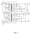
- the working principle of the present invention is shown in Figure 5 .
- the said high frequency resistance welding transformer is composed of two sub-transformers.
- each sub-transformer is composed of two transformer units.
- each transformer unit is composed of three primary coils (as 2, 3 in Figure 2 ) and two secondary coils (as 4, 5 in Figure 2 ).
- 1 indicates B coil of the primary coil unit of the transformer.
- 2 indicate a coil of the primary coil unit of the transformer.
- 3 indicates B coil of the primary coil unit of the transformer.
- 4 indicates secondary coil.
- 5 indicate the secondary coil.
- 6 indicate the magnetic core.
- 7 indicate the former shell.
- 8 indicate the center tap of the sub-transformer.
- 9 indicates negative output terminal (i.e. the center tap of the transformer) of the transformer and rectifier.
- 10 indicate the positive output terminal of the transformer and rectifier.
- 11 indicate cooling water connector.
- 12 indicate cooling water connector.
- 13 indicate rectifier diode heat sink.
- 14 indicate rectifier diode.
- Figure 3 shows an embodiment of transformer unit.
- a group of primary coils i.e. one B coil unit and one A coil unit and one B coil unit(1 indicates B coil of the primary coil unit of the transformer.
- 2 indicates A coil of the primary coil unit of the transformer.
- 3 indicates B coil of the primary coil unit of the transformer) and two secondary coil units connected end to end are alternately placed, as shown in figure 2 , wherein the order is that 1 indicating primary B coil, 4 indicating the secondary coil, 2 indicating primary A coil, 5 indicating the secondary coil, 3 indicating primary B coil, 8 indicating the center tap of two secondary coils connected end to end, 19 and 20 indicating the connecting terminal of the secondary which leads to the rectifier diode and has feature of electric and water.
- the primary coils of two transformer units said above are connected with the homonymous terminal.
- the center taps of the secondary coil are connected with each other.
- the other two terminals of the secondary coils are connected to corresponding rectifier diodes respectively, and fix the rectifier diodes on the radiator.
- two transformer units are arranged on the same magnetic core to compose a sub-transformer.
- the primary coils of two sub-transformers said above are connected in parallel i.e. connected with the homonymous terminals.
- the center taps of the said secondary coils are connected to negative output terminals of the transformer by multiple magnetic wires.
- the lead coil terminal of two groups of rectifier diodes of the secondary are connected to the anode of corresponding rectifier diodes, and then connected to the positive output terminal of the transformer by cathode i.e. heat sink of the rectifier diode.
- the said primary B coil of the transformer unit is formed by wrapping N (N ⁇ 1, 50>n> 10 natural number) magnetic wires to n turns.
- the A coil is formed by wrapping 2N magnetic wires to n turns.
- the two B coils is connected with the A coil end to end so as to form a primary coil unit.
- the said copper tube connecting the secondary coil and rectifier diodes is provided with circulating water for cooling.
- the said radiator of diodes is also provided with circulating water for cooling. Because the primary coil is adjacent to the secondary coil, the copper tube of secondary coil can take away the heat of the primary coil so as to achieve the object of cooling the primary coil.
- the circulating water pipe of copper tube for cooling the said secondary coils is communicated with the circulating water pipe of the rectifier diode heat sink to facilitate cooling and improve the duty rate of the transformer.
- the said magnetic core is selected PM or UYF type to increase the window area of transformer coil easily.
- the transformer design parameter i.e. the ratio of primary and secondary is (30-80):1.
- the said primary coil is formed by the braiding of multiple magnetic wires or flat magnetic wires with corresponding area.
- the said secondary coil is formed by wrapping one to four layers copper tubes one to two turns, wherein the copper tube is with a diameter of 3 to 10mm, wall thickness of 0.5 to 2 mm.
- the insulating material is polyethylene film with thickness of 0.05-0.1 mm.
- the output current is 3000-20000A.
- the output power is 10-200 KW.
- the duty rate is 10-50%.
Landscapes
- Engineering & Computer Science (AREA)
- Power Engineering (AREA)
- Dc-Dc Converters (AREA)
- General Induction Heating (AREA)
- Rectifiers (AREA)
- Coils Of Transformers For General Uses (AREA)
Description
- The present invention relates to a high frequency resistance welding transformer and a spot welding machine comprising said transformer. The present invention is suitable for the high frequency inverter switch power supply and resistance welding power supply.
- High frequency switch power supply technology is widely used in industry, agriculture and national defense currently, especially resistance welding, to reduce the volume of resistance welding machine and save an amount of copper. However, due to electronic devices, materials of high frequency transformer and the limitations of production process, distribution parameters (capacitance, inductance, leakage inductance and loss) of high frequency transformer are increased and high frequency transformer is difficult to output a large current at low voltage, particularly, the duty rate is lower and can not meet the needs of production. The disadvantages said above are mainly reflected in the following four aspects:
- First, because the capacitance and inductance are too large and magnetic circuit is too long and the leakage inductance is intense, the expect stress of IGBT is too high.
- Second, because the parameters of single transformer and the discreteness of performance, the prior art is difficult to use multiple transformers in parallel.
- Third, because multiple power supplies are connected in parallel, taking sharing current technology, responding slowly, high cost, complex circuit, the prior art is difficult to meet the requirements of spot welding machine and the volume is too large.
- Fourth, the loss of transformer is too large. The cooling of high frequency transformer is difficult. The duty rate is low.
- Any of
DE 10 2007 001 233 A1 ,US 5160820 ,CN 101430963A ,CN 201136079Y discloses a resistance welding high frequency transformer with a plurality of primary and secondary coils. - The object of the present invention is increasing the power of single transformer, reducing the number of transformers connected in parallel and reducing the volume of the transformer to reduce the leakage inductance of transformer and the discreteness of parameters. In addition, the present invention improves the duty rate of transformer by reducing transformer losses. In order to achieve the above purposes, a power high frequency transformer is divided into two sub-transformers and two transformer units per sub-transformer by breaking up the whole into parts so as to increase the duty rate and reduce the volume of the transformer.
- The present invention provides as technical solution a resistance welding high frequency transformer according to
present claim 1. Preferred embodiments are defined in the dependent claims. - The beneficial effect of the invention and of preferred embodiments thereof is described below.
- First, because the secondary coil is formed by wrapping copper tube which 3-10 mm in diameter and 0.5-2 mm in wall thickness, the present invention reduces the leakage inductance and the IGBT stress requirements.
- Second, the present invention uses copper tube to cooling by water so as to reduce the volume of transformer and improve the power and duty rate of the transformer.
- Third, different from the common high frequency power transformer, the transformer of present invention has advantages of small, light and high power factor so as to more suitable for the producing of high power suspension spot welding machine, wherein the transformer and welding clamp are integrated, and reduces the power consumption of high power suspension spot welding machine.
- Fourth, the transformer is provided with two sub-transformers. Each sub-transformer is provided with two transformer units. Each transformer unit is provided with multiple primary and secondary coils arranged at the same magnetic core. All transformer units can output respectively and compose a complete transformer.
- Fifth, the lead coils of the secondary coil and the rectifier diodes are connected directly by copper tube so as to solve the problem of electric and cooling by water. The rectifier diodes are evenly distributed to each coil of the secondary, thereby the rectifier diodes current sharing.
- Sixth, the heat dispersion and consume reduction of the primary are different from the secondary. The primary coil is adjacent to the secondary coil which is provided with water pipe; thereby the water pipe takes away the heat from the primary coil.
-
-
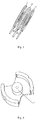
Figure 1 is a schematic drawing of the unitary transformer structure of a resistance welding high frquency transformer according to the present invention. -
Figure 2 is a schematic drawing of one group of primary and secondary coil units of a sub-transformer unit of a resistance welding high frquency transformer according to the present invention. -
Figure 3 is a schematic drawing of one group of primary coil of a resistance welding high frquency transformer according to the present invention. -
Figure 4 is a schematic drawing of a magnetic of a resistance welding high frquency transformer according to the present invention. -
Figure 5 is a schematic diagram of a transformer according to the present invention. - The present invention will be described in detail with reference to the figures and embodiments.
- The working principle of the present invention is shown in
Figure 5 . The said high frequency resistance welding transformer is composed of two sub-transformers. As shown in H unit, each sub-transformer is composed of two transformer units. As shown in J unit, each transformer unit is composed of three primary coils (as 2, 3 inFigure 2 ) and two secondary coils (as 4, 5 inFigure 2 ). - As shown in
Figure 1, 2 and4 , wherein, 1 indicates B coil of the primary coil unit of the transformer. 2 indicate a coil of the primary coil unit of the transformer. 3 indicates B coil of the primary coil unit of the transformer. 4 indicates secondary coil. 5 indicate the secondary coil. 6 indicate the magnetic core. 7 indicate the former shell. 8 indicate the center tap of the sub-transformer. 9 indicates negative output terminal (i.e. the center tap of the transformer) of the transformer and rectifier. 10 indicate the positive output terminal of the transformer and rectifier. 11 indicate cooling water connector. 12 indicate cooling water connector. 13 indicate rectifier diode heat sink. 14 indicate rectifier diode. -
Figure 3 shows an embodiment of transformer unit. A group of primary coils i.e. one B coil unit and one A coil unit and one B coil unit(1 indicates B coil of the primary coil unit of the transformer. 2 indicates A coil of the primary coil unit of the transformer. 3 indicates B coil of the primary coil unit of the transformer) and two secondary coil units connected end to end are alternately placed, as shown infigure 2 , wherein the order is that 1 indicating primary B coil, 4 indicating the secondary coil, 2 indicating primary A coil, 5 indicating the secondary coil, 3 indicating primary B coil, 8 indicating the center tap of two secondary coils connected end to end, 19 and 20 indicating the connecting terminal of the secondary which leads to the rectifier diode and has feature of electric and water. - The primary coils of two transformer units said above are connected with the homonymous terminal. The center taps of the secondary coil are connected with each other. The other two terminals of the secondary coils are connected to corresponding rectifier diodes respectively, and fix the rectifier diodes on the radiator. Then two transformer units are arranged on the same magnetic core to compose a sub-transformer.
- The primary coils of two sub-transformers said above are connected in parallel i.e. connected with the homonymous terminals. The center taps of the said secondary coils are connected to negative output terminals of the transformer by multiple magnetic wires. The lead coil terminal of two groups of rectifier diodes of the secondary are connected to the anode of corresponding rectifier diodes, and then connected to the positive output terminal of the transformer by cathode i.e. heat sink of the rectifier diode.
- The said primary B coil of the transformer unit is formed by wrapping N (N≥1, 50>n> 10 natural number) magnetic wires to n turns. The A coil is formed by wrapping 2N magnetic wires to n turns. The two B coils is connected with the A coil end to end so as to form a primary coil unit.
- The said copper tube connecting the secondary coil and rectifier diodes is provided with circulating water for cooling. The said radiator of diodes is also provided with circulating water for cooling. Because the primary coil is adjacent to the secondary coil, the copper tube of secondary coil can take away the heat of the primary coil so as to achieve the object of cooling the primary coil.
- The circulating water pipe of copper tube for cooling the said secondary coils is communicated with the circulating water pipe of the rectifier diode heat sink to facilitate cooling and improve the duty rate of the transformer.
- The said magnetic core is selected PM or UYF type to increase the window area of transformer coil easily.
- The transformer design parameter i.e. the ratio of primary and secondary is (30-80):1. The said primary coil is formed by the braiding of multiple magnetic wires or flat magnetic wires with corresponding area. The said secondary coil is formed by wrapping one to four layers copper tubes one to two turns, wherein the copper tube is with a diameter of 3 to 10mm, wall thickness of 0.5 to 2 mm. The insulating material is polyethylene film with thickness of 0.05-0.1 mm. The output current is 3000-20000A. The output power is 10-200 KW. The duty rate is 10-50%.
- Although preferred embodiments of the present invention are disclosed for purpose of illustration, various modifications are possible within the scope of the present invention as outlined in the claims appended hereto.
Claims (13)
- A resistance welding high frequency transformer, including:- a transformer shell (7),- exactly two sub-transformers, wherein each of the two sub-transformers has an own magnetic core (6) and exactly two transformer units, wherein each transformer unit has one primary coil unit (A, B, B; 1, 2, 3) and one secondary coil unit (4, 5),
wherein all primary coil units of the resistance welding high frequency transformer are in parallel connection, wherein each primary coil unit (A, B, B; 1, 2, 3) includes exactly two primary B coils and exactly one primary A coil, wherein the two primary B coils are in parallel connection and then in series connection with the one primary A coil,
wherein all secondary coil units of the resistance welding high frequency transformer are in parallel connection, wherein each secondary coil unit includes exactly two secondary coils (4, 5) and has a tap where the two secondary coils (4, 5) are connected end to end to each other,- a full wave rectifier having rectifier diodes (14),- cooling water pipes,- a heat sink (13) for fixing the rectifier diodes (14),- a first center tap (8, Q) connected to the tap of each of the secondary coil units,- a positive (10) and a negative (9) output terminal, wherein either the negative (9) or the positive (10) output terminal is connected to the first center tap (8, Q). - The resistance welding high frequency transformer according to claim 1, wherein, each of the other two lead terminals (O, P) of the secondary coil units is connected to an anode of a corresponding one of the rectifier diodes (14), if the negative output terminal (9) is connected to the first center tap (8, Q), or wherein each of the other two lead terminals (O, P) of the secondary coil units is connected to a cathode of a corresponding one of the rectifier diodes (14), if the positive output terminal (10) is connected to the first center tap (8, Q).
- The resistance welding high frequency transformer according to claim 1 or 2, wherein said three coils (1, 2, 3) of said primary coil unit (A, B, B) and said two secondary coils (4, 5) of said secondary coil unit are alternately placed, wherein the primary B coils are located outside of the two secondary coils (4, 5) and the primary A coil is located between the two secondary coils (4, 5), wherein said primary and secondary coil units of said transformer units of each sub-transformer are uniformly placed on a circular cylinder of a same core (6) of the corresponding sub-transformer according to the above order.
- The resistance welding high frequency transformer of claim 3, wherein the rectifier of said transformer includes two sets of diodes (14), wherein diodes (14) of the two sets of diodes (14) and the pair of secondary coils of one of said secondary coil units form a full wave rectifier circuit;
wherein, if the negative output terminal (9) is connected to the first center tap (8, Q), each of the other two lead terminals (O, P) of the secondary coil units is connected to an anode of a corresponding one of the rectifier diodes (14), wherein each cathode of said rectifier diodes (14) is connected to said heat sink (13) with water, wherein said rectifier diodes (14) are fixed on the heat sink (13) as positive output terminal (10) of the transformer;
wherein, if the positive output terminal (10) is connected to the first center tap (8, Q), each of the other two lead terminals (O, P) of the secondary coil units is connected to a cathode of a corresponding one of the rectifier diodes (14), wherein each anode of said rectifier diodes (14) is connected to said heat sink (13) with water, wherein said rectifier diodes (14) are fixed on said heat sink (13) as negative output terminal (9) of the transformer. - The resistance welding high frequency transformer according to claim 4, wherein each of said secondary coils (4, 5) is connected with the corresponding rectifier diode (14) by a water tube made of copper.
- The resistance welding high frequency transformer according to claim 5, wherein said water tube made of copper is provided with circulating water for cooling, wherein said heat sink (13) of the rectifier diode (14) is also provided with circulating water.
- The resistance welding high frequency transformer according to claim 1, wherein each primary B coil of each primary coil unit (A, B, B) is formed by wrapping N flat or non-flat wires with a diameter of 0.3 to 1.0 mm to n turns, wherein each primary A coil is formed by wrapping 2N flat or non-flat wires with a diameter of 0.3 to 1.0 mm to n turns, wherein said two primary B coils of each primary coil unit (A, B, B) are in parallel connection and then in series connection with the corresponding primary A coil.
- The resistance welding high frequency transformer according to claim 7, wherein each primary coil (1, 2, 3) is formed by braiding of multiple wires or wrapping of flat copper wires.
- The resistance welding high frequency transformer according to claim 2, wherein each of said secondary coils (4, 5) is formed by wrapping one to four layers of copper tube one to two turns, wherein the copper tube has a diameter of 3 to 10 mm and a wall thickness of 0.5 to 2 mm.
- The resistance welding high frequency transformer according to claim 6, wherein said water tube made of copper for cooling said secondary coils (4, 5) is communicating with the water tube for cooling said heat sink (13).
- The resistance welding high frequency transformer according to claim 1, wherein the magnetic core (6) is of PM or UYF type.
- The resistance welding high frequency transformer according to any of claims 1 to 11, wherein the ratio of primary and secondary is (30-80):1, and an insulating material is polyethylene film with thickness of 0.05-0.1 mm, and an output current is 3000-20000 A, and an output power is 10-200 KW, and a duty rate is 10-50%.
- A secondary high frequency spot welding machine, comprising a resistance welding high frequency transformer according to anyone of the claims 1 to 12.
Applications Claiming Priority (2)
| Application Number | Priority Date | Filing Date | Title |
|---|---|---|---|
| CN2010101304665A CN101800123B (en) | 2010-03-23 | 2010-03-23 | High-frequency transformer of resistance welding machine |
| PCT/CN2010/072916 WO2011116544A1 (en) | 2010-03-23 | 2010-05-19 | Resistance welding high frequency transformer and spot welding machine |
Publications (3)
| Publication Number | Publication Date |
|---|---|
| EP2551861A1 EP2551861A1 (en) | 2013-01-30 |
| EP2551861A4 EP2551861A4 (en) | 2016-03-23 |
| EP2551861B1 true EP2551861B1 (en) | 2017-07-19 |
Family
ID=42595750
Family Applications (1)
| Application Number | Title | Priority Date | Filing Date |
|---|---|---|---|
| EP10848206.8A Active EP2551861B1 (en) | 2010-03-23 | 2010-05-19 | Resistance welding high frequency transformer and spot welding machine |
Country Status (4)
| Country | Link |
|---|---|
| US (1) | US8952286B2 (en) |
| EP (1) | EP2551861B1 (en) |
| CN (1) | CN101800123B (en) |
| WO (1) | WO2011116544A1 (en) |
Families Citing this family (11)
| Publication number | Priority date | Publication date | Assignee | Title |
|---|---|---|---|---|
| US20140104912A1 (en) * | 2011-06-08 | 2014-04-17 | Shenzhen Hongbai Technology Industrail Co., Ltd | Water cooling sub-high frequency transformer and cooling device thereof |
| CN102646510B (en) * | 2012-04-26 | 2015-03-11 | 华南理工大学 | Water-cooling type high-frequency transformer and secondary rectifier |
| CN103366932B (en) * | 2013-08-02 | 2016-01-13 | 深圳市鸿栢科技实业有限公司 | Medium/high frequency transformer |
| CN103490637A (en) * | 2013-10-15 | 2014-01-01 | 重庆乾合科技有限公司 | High-power adjustable power supply |
| CA3008661C (en) * | 2015-12-22 | 2025-06-03 | Thermatool Corp. | High frequency power supply system with closely regulated output for heating a workpiece |
| US10405378B2 (en) * | 2015-12-22 | 2019-09-03 | Thermatool Corp. | High frequency power supply system with closely regulated output for heating a workpiece |
| CN111896799B (en) * | 2020-08-05 | 2023-08-08 | 合肥零碳技术有限公司 | Calculation method and device for average loss of power device |
| CN112820515B (en) * | 2021-01-08 | 2022-03-11 | 合肥三宇电器有限责任公司 | A low-voltage high-current power supply device |
| CN112756758B (en) * | 2021-01-08 | 2024-05-28 | 合肥三宇电器有限责任公司 | A low-voltage, high-current, lightweight spot welding machine |
| CN116638247B (en) * | 2023-07-12 | 2026-02-27 | 昆山联滔电子有限公司 | Coil welding positioning method and equipment |
| CN118882231A (en) * | 2024-07-22 | 2024-11-01 | 浙江先导热电科技股份有限公司 | An integrated wireless charging magnetic refrigeration module and a wireless charging device |
Family Cites Families (13)
| Publication number | Priority date | Publication date | Assignee | Title |
|---|---|---|---|---|
| GB1597870A (en) * | 1977-06-03 | 1981-09-16 | Inoue Japax Res | Electrical machining power supply apparatus |
| GB2225972B (en) * | 1988-12-15 | 1993-05-26 | Honda Motor Co Ltd | Resistance welding apparatus |
| GB2243248B (en) * | 1990-03-30 | 1994-10-26 | Honda Motor Co Ltd | Welding transformer and method of manufacturing same |
| US5668421A (en) * | 1995-04-06 | 1997-09-16 | E. B. Eddy Forest Products Ltd. | Pressurized air-gap guided active linear motor suspension system |
| US5902506A (en) * | 1995-12-08 | 1999-05-11 | Thermatool Corp. | Matching apparatus for connecting high frequency solid state electrical power generator to a load |
| US5770909A (en) * | 1996-12-13 | 1998-06-23 | Rosen Motors, L.P. | Wound rotor synchronous motor-generator and field control system therefor |
| DE20111509U1 (en) * | 2000-07-25 | 2001-09-13 | NIMAK Widerstandsschweißmaschinen GmbH, 56472 Nisterberg | Power source for a resistance welding machine |
| CN100364709C (en) * | 2005-11-18 | 2008-01-30 | 北京工业大学 | A medium frequency resistance welding inverter power supply device |
| DE102007001233A1 (en) * | 2007-01-08 | 2008-07-10 | Robert Bosch Gmbh | Winding element for a coil winding and transformer arrangement |
| CN201136079Y (en) * | 2007-12-29 | 2008-10-22 | 天津七所高科技有限公司 | Intermediate frequency parallel voltage transformation and rectification circuit of resistance spot welding machine |
| CN101430963B (en) * | 2008-08-19 | 2011-03-16 | 深圳市鸿栢科技实业有限公司 | High-frequency transformer of spot welding machine |
| CN101422846B (en) * | 2008-08-29 | 2011-09-07 | 深圳市鸿栢科技实业有限公司 | High-frequency invert direct-current point-welding device |
| CN201796715U (en) * | 2010-03-23 | 2011-04-13 | 深圳市鸿栢科技实业有限公司 | High-frequency transformer for resistance welding |
-
2010
- 2010-03-23 CN CN2010101304665A patent/CN101800123B/en not_active Expired - Fee Related
- 2010-05-19 US US13/636,336 patent/US8952286B2/en active Active - Reinstated
- 2010-05-19 EP EP10848206.8A patent/EP2551861B1/en active Active
- 2010-05-19 WO PCT/CN2010/072916 patent/WO2011116544A1/en not_active Ceased
Non-Patent Citations (1)
| Title |
|---|
| None * |
Also Published As
| Publication number | Publication date |
|---|---|
| EP2551861A1 (en) | 2013-01-30 |
| US8952286B2 (en) | 2015-02-10 |
| CN101800123B (en) | 2012-07-11 |
| US20130008877A1 (en) | 2013-01-10 |
| WO2011116544A1 (en) | 2011-09-29 |
| CN101800123A (en) | 2010-08-11 |
| EP2551861A4 (en) | 2016-03-23 |
Similar Documents
| Publication | Publication Date | Title |
|---|---|---|
| US8952286B2 (en) | Resistance welding high frequency transformer and spot welding machine | |
| CN103366933B (en) | A kind of integral high frequency power transformer | |
| CN211907191U (en) | Transformer and power based on primary side fractional turn | |
| CN102956350A (en) | Integrated high-frequency power transformer | |
| CN210325449U (en) | Magnetic integration type high-power-density series-parallel planar transformer of LLC half-bridge circuit | |
| CN102646510B (en) | Water-cooling type high-frequency transformer and secondary rectifier | |
| CN201418026Y (en) | Circuit for reducing conducted interference of high frequency high-power switch power supply | |
| CN202889177U (en) | Water-cooling high power high frequency switching power supply device | |
| CN102957302A (en) | Water-cooled high-power high-frequency switching power supply device | |
| CN209691550U (en) | High frequency transformer | |
| CN205282266U (en) | High frequency invertion power supply | |
| CN203481015U (en) | High-power medium-frequency isolation transformer | |
| CN102684524B (en) | A kind of high-efficiency inverter | |
| CN209232549U (en) | A kind of liquid-cooling type high-frequency switch power transformer | |
| CN203366967U (en) | Integrated high-frequency power transformer | |
| CN203085322U (en) | Water-cooling high-power high-frequency power transformer | |
| CN201638664U (en) | Built-in transformer of LED daylight lamp | |
| CN100364709C (en) | A medium frequency resistance welding inverter power supply device | |
| CN207743884U (en) | A kind of water-cooled high-power high frequency rectifying device | |
| CN213151912U (en) | High-power phase-shifted full-bridge circuit based on twin-coil follow current inductor | |
| CN203827202U (en) | Full water cooling high frequency power transformer and secondary rectifier module structure | |
| CN103973133A (en) | Full-water-cooling high-frequency power transformer and secondary rectifying module structure | |
| CN206640506U (en) | A kind of water cooling high-power high-frequency coloring power source | |
| CN204289041U (en) | A kind of clamping plate type transformer | |
| CN216311569U (en) | Transformer and filter device |
Legal Events
| Date | Code | Title | Description |
|---|---|---|---|
| PUAI | Public reference made under article 153(3) epc to a published international application that has entered the european phase |
Free format text: ORIGINAL CODE: 0009012 |
|
| 17P | Request for examination filed |
Effective date: 20120723 |
|
| AK | Designated contracting states |
Kind code of ref document: A1 Designated state(s): AL AT BE BG CH CY CZ DE DK EE ES FI FR GB GR HR HU IE IS IT LI LT LU LV MC MK MT NL NO PL PT RO SE SI SK SM TR |
|
| DAX | Request for extension of the european patent (deleted) | ||
| REG | Reference to a national code |
Ref country code: DE Ref legal event code: R079 Ref document number: 602010043802 Country of ref document: DE Free format text: PREVIOUS MAIN CLASS: H01F0027280000 Ipc: H01F0038080000 |
|
| RA4 | Supplementary search report drawn up and despatched (corrected) |
Effective date: 20160222 |
|
| RIC1 | Information provided on ipc code assigned before grant |
Ipc: H01F 38/08 20060101AFI20160216BHEP Ipc: H01F 27/40 20060101ALI20160216BHEP Ipc: H01F 27/28 20060101ALI20160216BHEP |
|
| 17Q | First examination report despatched |
Effective date: 20160708 |
|
| GRAP | Despatch of communication of intention to grant a patent |
Free format text: ORIGINAL CODE: EPIDOSNIGR1 |
|
| INTG | Intention to grant announced |
Effective date: 20170301 |
|
| GRAS | Grant fee paid |
Free format text: ORIGINAL CODE: EPIDOSNIGR3 |
|
| GRAA | (expected) grant |
Free format text: ORIGINAL CODE: 0009210 |
|
| AK | Designated contracting states |
Kind code of ref document: B1 Designated state(s): AL AT BE BG CH CY CZ DE DK EE ES FI FR GB GR HR HU IE IS IT LI LT LU LV MC MK MT NL NO PL PT RO SE SI SK SM TR |
|
| REG | Reference to a national code |
Ref country code: GB Ref legal event code: FG4D |
|
| REG | Reference to a national code |
Ref country code: CH Ref legal event code: EP |
|
| REG | Reference to a national code |
Ref country code: IE Ref legal event code: FG4D |
|
| REG | Reference to a national code |
Ref country code: AT Ref legal event code: REF Ref document number: 911108 Country of ref document: AT Kind code of ref document: T Effective date: 20170815 |
|
| REG | Reference to a national code |
Ref country code: DE Ref legal event code: R096 Ref document number: 602010043802 Country of ref document: DE |
|
| REG | Reference to a national code |
Ref country code: NL Ref legal event code: MP Effective date: 20170719 |
|
| REG | Reference to a national code |
Ref country code: LT Ref legal event code: MG4D |
|
| REG | Reference to a national code |
Ref country code: AT Ref legal event code: MK05 Ref document number: 911108 Country of ref document: AT Kind code of ref document: T Effective date: 20170719 |
|
| PG25 | Lapsed in a contracting state [announced via postgrant information from national office to epo] |
Ref country code: LT Free format text: LAPSE BECAUSE OF FAILURE TO SUBMIT A TRANSLATION OF THE DESCRIPTION OR TO PAY THE FEE WITHIN THE PRESCRIBED TIME-LIMIT Effective date: 20170719 Ref country code: AT Free format text: LAPSE BECAUSE OF FAILURE TO SUBMIT A TRANSLATION OF THE DESCRIPTION OR TO PAY THE FEE WITHIN THE PRESCRIBED TIME-LIMIT Effective date: 20170719 Ref country code: NO Free format text: LAPSE BECAUSE OF FAILURE TO SUBMIT A TRANSLATION OF THE DESCRIPTION OR TO PAY THE FEE WITHIN THE PRESCRIBED TIME-LIMIT Effective date: 20171019 Ref country code: NL Free format text: LAPSE BECAUSE OF FAILURE TO SUBMIT A TRANSLATION OF THE DESCRIPTION OR TO PAY THE FEE WITHIN THE PRESCRIBED TIME-LIMIT Effective date: 20170719 Ref country code: FI Free format text: LAPSE BECAUSE OF FAILURE TO SUBMIT A TRANSLATION OF THE DESCRIPTION OR TO PAY THE FEE WITHIN THE PRESCRIBED TIME-LIMIT Effective date: 20170719 Ref country code: HR Free format text: LAPSE BECAUSE OF FAILURE TO SUBMIT A TRANSLATION OF THE DESCRIPTION OR TO PAY THE FEE WITHIN THE PRESCRIBED TIME-LIMIT Effective date: 20170719 Ref country code: SE Free format text: LAPSE BECAUSE OF FAILURE TO SUBMIT A TRANSLATION OF THE DESCRIPTION OR TO PAY THE FEE WITHIN THE PRESCRIBED TIME-LIMIT Effective date: 20170719 |
|
| PG25 | Lapsed in a contracting state [announced via postgrant information from national office to epo] |
Ref country code: BG Free format text: LAPSE BECAUSE OF FAILURE TO SUBMIT A TRANSLATION OF THE DESCRIPTION OR TO PAY THE FEE WITHIN THE PRESCRIBED TIME-LIMIT Effective date: 20171019 Ref country code: GR Free format text: LAPSE BECAUSE OF FAILURE TO SUBMIT A TRANSLATION OF THE DESCRIPTION OR TO PAY THE FEE WITHIN THE PRESCRIBED TIME-LIMIT Effective date: 20171020 Ref country code: IS Free format text: LAPSE BECAUSE OF FAILURE TO SUBMIT A TRANSLATION OF THE DESCRIPTION OR TO PAY THE FEE WITHIN THE PRESCRIBED TIME-LIMIT Effective date: 20171119 Ref country code: ES Free format text: LAPSE BECAUSE OF FAILURE TO SUBMIT A TRANSLATION OF THE DESCRIPTION OR TO PAY THE FEE WITHIN THE PRESCRIBED TIME-LIMIT Effective date: 20170719 Ref country code: PL Free format text: LAPSE BECAUSE OF FAILURE TO SUBMIT A TRANSLATION OF THE DESCRIPTION OR TO PAY THE FEE WITHIN THE PRESCRIBED TIME-LIMIT Effective date: 20170719 Ref country code: LV Free format text: LAPSE BECAUSE OF FAILURE TO SUBMIT A TRANSLATION OF THE DESCRIPTION OR TO PAY THE FEE WITHIN THE PRESCRIBED TIME-LIMIT Effective date: 20170719 |
|
| REG | Reference to a national code |
Ref country code: DE Ref legal event code: R097 Ref document number: 602010043802 Country of ref document: DE |
|
| PG25 | Lapsed in a contracting state [announced via postgrant information from national office to epo] |
Ref country code: CZ Free format text: LAPSE BECAUSE OF FAILURE TO SUBMIT A TRANSLATION OF THE DESCRIPTION OR TO PAY THE FEE WITHIN THE PRESCRIBED TIME-LIMIT Effective date: 20170719 Ref country code: RO Free format text: LAPSE BECAUSE OF FAILURE TO SUBMIT A TRANSLATION OF THE DESCRIPTION OR TO PAY THE FEE WITHIN THE PRESCRIBED TIME-LIMIT Effective date: 20170719 Ref country code: DK Free format text: LAPSE BECAUSE OF FAILURE TO SUBMIT A TRANSLATION OF THE DESCRIPTION OR TO PAY THE FEE WITHIN THE PRESCRIBED TIME-LIMIT Effective date: 20170719 |
|
| REG | Reference to a national code |
Ref country code: FR Ref legal event code: PLFP Year of fee payment: 9 |
|
| PLBE | No opposition filed within time limit |
Free format text: ORIGINAL CODE: 0009261 |
|
| STAA | Information on the status of an ep patent application or granted ep patent |
Free format text: STATUS: NO OPPOSITION FILED WITHIN TIME LIMIT |
|
| PG25 | Lapsed in a contracting state [announced via postgrant information from national office to epo] |
Ref country code: SK Free format text: LAPSE BECAUSE OF FAILURE TO SUBMIT A TRANSLATION OF THE DESCRIPTION OR TO PAY THE FEE WITHIN THE PRESCRIBED TIME-LIMIT Effective date: 20170719 Ref country code: IT Free format text: LAPSE BECAUSE OF FAILURE TO SUBMIT A TRANSLATION OF THE DESCRIPTION OR TO PAY THE FEE WITHIN THE PRESCRIBED TIME-LIMIT Effective date: 20170719 Ref country code: SM Free format text: LAPSE BECAUSE OF FAILURE TO SUBMIT A TRANSLATION OF THE DESCRIPTION OR TO PAY THE FEE WITHIN THE PRESCRIBED TIME-LIMIT Effective date: 20170719 Ref country code: EE Free format text: LAPSE BECAUSE OF FAILURE TO SUBMIT A TRANSLATION OF THE DESCRIPTION OR TO PAY THE FEE WITHIN THE PRESCRIBED TIME-LIMIT Effective date: 20170719 |
|
| 26N | No opposition filed |
Effective date: 20180420 |
|
| PG25 | Lapsed in a contracting state [announced via postgrant information from national office to epo] |
Ref country code: SI Free format text: LAPSE BECAUSE OF FAILURE TO SUBMIT A TRANSLATION OF THE DESCRIPTION OR TO PAY THE FEE WITHIN THE PRESCRIBED TIME-LIMIT Effective date: 20170719 |
|
| REG | Reference to a national code |
Ref country code: CH Ref legal event code: PL |
|
| GBPC | Gb: european patent ceased through non-payment of renewal fee |
Effective date: 20180519 |
|
| REG | Reference to a national code |
Ref country code: BE Ref legal event code: MM Effective date: 20180531 |
|
| PG25 | Lapsed in a contracting state [announced via postgrant information from national office to epo] |
Ref country code: MC Free format text: LAPSE BECAUSE OF FAILURE TO SUBMIT A TRANSLATION OF THE DESCRIPTION OR TO PAY THE FEE WITHIN THE PRESCRIBED TIME-LIMIT Effective date: 20170719 |
|
| REG | Reference to a national code |
Ref country code: IE Ref legal event code: MM4A |
|
| PG25 | Lapsed in a contracting state [announced via postgrant information from national office to epo] |
Ref country code: LI Free format text: LAPSE BECAUSE OF NON-PAYMENT OF DUE FEES Effective date: 20180531 Ref country code: CH Free format text: LAPSE BECAUSE OF NON-PAYMENT OF DUE FEES Effective date: 20180531 |
|
| PG25 | Lapsed in a contracting state [announced via postgrant information from national office to epo] |
Ref country code: LU Free format text: LAPSE BECAUSE OF NON-PAYMENT OF DUE FEES Effective date: 20180519 |
|
| PG25 | Lapsed in a contracting state [announced via postgrant information from national office to epo] |
Ref country code: GB Free format text: LAPSE BECAUSE OF NON-PAYMENT OF DUE FEES Effective date: 20180519 Ref country code: IE Free format text: LAPSE BECAUSE OF NON-PAYMENT OF DUE FEES Effective date: 20180519 |
|
| PG25 | Lapsed in a contracting state [announced via postgrant information from national office to epo] |
Ref country code: BE Free format text: LAPSE BECAUSE OF NON-PAYMENT OF DUE FEES Effective date: 20180531 |
|
| PG25 | Lapsed in a contracting state [announced via postgrant information from national office to epo] |
Ref country code: MT Free format text: LAPSE BECAUSE OF NON-PAYMENT OF DUE FEES Effective date: 20180519 |
|
| PG25 | Lapsed in a contracting state [announced via postgrant information from national office to epo] |
Ref country code: TR Free format text: LAPSE BECAUSE OF FAILURE TO SUBMIT A TRANSLATION OF THE DESCRIPTION OR TO PAY THE FEE WITHIN THE PRESCRIBED TIME-LIMIT Effective date: 20170719 |
|
| PG25 | Lapsed in a contracting state [announced via postgrant information from national office to epo] |
Ref country code: PT Free format text: LAPSE BECAUSE OF FAILURE TO SUBMIT A TRANSLATION OF THE DESCRIPTION OR TO PAY THE FEE WITHIN THE PRESCRIBED TIME-LIMIT Effective date: 20170719 Ref country code: HU Free format text: LAPSE BECAUSE OF FAILURE TO SUBMIT A TRANSLATION OF THE DESCRIPTION OR TO PAY THE FEE WITHIN THE PRESCRIBED TIME-LIMIT; INVALID AB INITIO Effective date: 20100519 |
|
| PG25 | Lapsed in a contracting state [announced via postgrant information from national office to epo] |
Ref country code: MK Free format text: LAPSE BECAUSE OF NON-PAYMENT OF DUE FEES Effective date: 20170719 Ref country code: CY Free format text: LAPSE BECAUSE OF FAILURE TO SUBMIT A TRANSLATION OF THE DESCRIPTION OR TO PAY THE FEE WITHIN THE PRESCRIBED TIME-LIMIT Effective date: 20170719 |
|
| PG25 | Lapsed in a contracting state [announced via postgrant information from national office to epo] |
Ref country code: AL Free format text: LAPSE BECAUSE OF FAILURE TO SUBMIT A TRANSLATION OF THE DESCRIPTION OR TO PAY THE FEE WITHIN THE PRESCRIBED TIME-LIMIT Effective date: 20170719 |
|
| PGFP | Annual fee paid to national office [announced via postgrant information from national office to epo] |
Ref country code: DE Payment date: 20250513 Year of fee payment: 16 |
|
| PGFP | Annual fee paid to national office [announced via postgrant information from national office to epo] |
Ref country code: FR Payment date: 20250530 Year of fee payment: 16 |